Operating and maintenance manual Control valve ECOTROL Series 8C / 1.1
|
|
|
- Aron Osborne
- 6 years ago
- Views:
Transcription


1 Operating and maintenance manual Control valve ECOTROL Series 8C / 1.1
2 Original instructions ARCA Regler GmbH. All rights reserved. Cover picture background: Freepik.com
3 ARCA Regler GmbH Table of contents Table of contents 1 General data Validity of the manual Contact details Other applicable documents Place of storage of the manual Safety General safety information Explanation of symbols and notices Structure of the warning notices Intended use Inappropriate use Residual risks Qualification of the personnel Operator's duty of care Personal protective equipment Transport, storage and packaging Transport Storage Packaging Type plate Type key Sectional drawings Parts list C1-P C1-P C1-L1-LK C1-P1-BG C3-L C4-P C5-P1 to -50 C C7-P Functional description Fitting Commissioning / Decommissioning Maintenance Care Maintenance Stem seal Detail X Series 8C / / 38
4 Table of contents ARCA Regler GmbH V-collars Packing rings Shaped ring Disassembly / assembly of the valve Procedure Actuator Bonnet Stem sealing Plain bearing Intermediate flange (version with bellows) Cylinder tube (version with balancing system) Plug Stem Balancing seal - Detail Z (version with balancing system) Retainer & seat Torque tables - bolted connections Screws according to DIN EN ISO 4017/4014, DIN Screws according to DIN Screws according to ASME B Fault removal Disposal and recycling / / 1.1 Series 8C
5 ARCA Regler GmbH 1 General data 1 General data This operating manual contains instructions that enable the product to be safely and properly installed, put into operation and maintained. The target group for this operating manual is exclusively specially trained and authorised technical personnel. Please contact the manufacturer if you encounter problems that cannot be solved with the aid of this operating manual. The product is subject to technical changes at any time. 1.1 Validity of the manual This operating manual applies to the product in the version described in the device pass. 1.2 Contact details Further information about the product can be obtained from: Manufacturer's address ARCA Regler GmbH Kempener Str. 18 D Tönisvorst Tel.: +49 (0) Fax: +49 (0) sale@arca-valve.com Other applicable documents The product can be delivered as part of an actuator and equipped with additional components that are described in their own operating manuals. The instructions as well as the warning and safety information contained therein must also be observed. Furthermore, the following documents apply in addition to this operating manual. Device pass Installation drawing 1.4 Place of storage of the manual The operating manual and all other applicable documents are part of the product. They must be kept in the immediate vicinity of the product and must be accessible to the personnel at all times. Series 8C / / 38
6 2 Safety ARCA Regler GmbH 2 Safety 2.1 General safety information The operating manual contains detailed descriptions for the safe installation, commissioning and maintenance of the product. Read this operating manual attentively in its entirety in order to familiarise yourself with the product. Particular attention must be paid to the information in this chapter. 2.2 Explanation of symbols and notices Safety and warning instructions are intended to avoid hazards to the life or health of operating or maintenance personnel, and to avoid material damage. It is emphasised through the use of the special terms defined here. Additionally, their location is marked by warning symbols (pictograms). The signal terms used have the following meanings: DANGER means that death, serious injuries and/or considerable damage to property will occur if the corresponding preventive measures are not taken and maintained. WARNING means that death, serious injuries and/or considerable damage to property can occur if the corresponding preventive measures are not taken and maintained. CAUTION means that minor injuries and/or damage to property can occur if the corresponding preventive measures are not taken and maintained. NOTICE indicates an important item of information about the product itself or how the product should be handled, to which special attention should be paid. 6 / / 1.1 Series 8C
7 ARCA Regler GmbH 2 Safety 2.3 Structure of the warning notices Section-related warning notice Section-related warning notices refer to the entire chapter, sections or several paragraphs within this operating manual. Section-related warning notices are structured as follows: DANGER Type and source of the danger Possible consequences of disregard Measure to avoid the danger Further measures Embedded warning notice Embedded warning notices refer to a certain area within a section. They apply to smaller information units than the section-related warning notices. Embedded warning notices are structured as follows: DANGER! Instructions for avoiding a dangerous situation. 2.4 Intended use The product complies with laws, regulations and standards valid at the time of delivery. The product does not pose a danger to people, property or environment if it is used for its intended purpose and the warning notices contained in this operating manual and attached to the product are observed. This applies to the entire lifetime, from the delivery, assembly and operation to the disassembly and disposal. The following is deemed to be used for the intended purpose: Operate the product exclusively in accordance with this operating manual and in accordance with the specification in the order confirmation and the device pass. Use exclusively original ARCA spare parts for the maintenance of the product. DANGER Risk of death and serious injuries as well as damage to property and the environment! Risk of death and serious injuries as well as damage to property and the environment due to hazardous operating media, high temperatures and pressures as well as moving parts. The following requirements and conditions must be complied with without fail. Observe warning notices. Maintenance Ensure or observe the following before performing any maintenance work: Depressurise the pipeline. Completely empty the pipeline and, in the case of hazardous operating media, thoroughly rinse it using a suitable cleaning fluid. Series 8C / / 38
8 2 Safety ARCA Regler GmbH Inform yourself about possible hazards that could arise due to residues of the operating medium and take suitable precautions if necessary. (Wear personal protective equipment, etc.). If necessary, cool the valve down or heat it up to ambient temperature. Disconnect the auxiliary energy supply to the actuator and drive it to its end position. Ensure that the system cannot be started up by third parties. You are expressly directed to observe the regulations for potentially explosive equipment where necessary. 2.5 Inappropriate use Inappropriate use is use of the product other than as described is the chapter entitled [2.4] Intended use. In the addition, the following applies: Unauthorised modifications to the product can lead to injuries, damage to property and malfunctions. The user alone bears this risk. Warranty and liability claims are excluded. 2.6 Residual risks There may still be residual risks even if the product is used for its intended purpose. Danger of being crushed by unsecured actuators In case of negligent use of personal protective equipment: Danger due to noise resulting in hearing loss Thermal hazards (burning, scalding, etc.) Danger due to escape of the operating medium Furthermore, there may be unapparent residual risks despite all precautions taken. Residual risks can be minimised if the notes on safety and commissioning as well as the operating manual as a whole are observed. 2.7 Qualification of the personnel The product is exclusively intended for use in plants and installations in which trained technical personnel carry out the necessary work. Technical personnel are persons who are entrusted with the installation, commissioning and operation of this product and who have the appropriate qualifications for their work activities, such as, for example: training or instruction in accordance with current technical safety standards in the maintenance and usage of appropriate safety equipment. Training in First Aid. In the case of systems with explosion protection: training or instruction and authorisation to carry out work on potentially explosive systems. 8 / / 1.1 Series 8C
9 ARCA Regler GmbH 2 Safety Persons Activity Repair work may be carried out only by trained and qualified technical personnel. Work on electrical equipment may be carried out only by trained electricians or persons who have received electrotechnical instruction. Instructed persons Persons Persons with a recognised technical education with a recognised electrotechnical education Superiors with relevant skills ARCA service personnel Transport X X X X X Installation X X X X X Commissioning X X X X Maintenance X X X X X Fault finding X X X Mechanical troubleshooting Electrical troubleshooting Repairs X X X X Disposal X X X X X X X X X 2.8 Operator's duty of care To avoid accidents, malfunctions and environmental impacts, the respective person responsible for the transport, commissioning, operation, maintenance and disposal of the product must ensure the following: Observation of all warning and danger notices. Regular instruction of personnel on all applicable questions of work safety, the operating manual and in particular the safety instructions that it contains. Regulations and work instructions for safe working as well as the corresponding instructions for the conduct of the personnel in case of accidents and fire are to be kept at the ready at all times and hung up in the plant if necessary. Operate the product only if it is in perfect working order. Use only spare parts, lubricants and operating resources approved by the manufacturer. Observe the specified operating conditions and requirements at the place of installation. Provide all necessary devices and the personal protective equipment required for the respective task. Refer to the chapter entitled Maintenance for the prescribed maintenance intervals and comply with the corresponding regulations. Allow installation, commissioning and maintenance of the product to be carried out only by qualified and trained personnel in accordance with this operating manual. The operator must ensure that the product is used for its intended purpose. Series 8C / / 38


10 2 Safety ARCA Regler GmbH Before commissioning the product the operator must carry out a risk assessment and define appropriate inspection and maintenance intervals according to the operating conditions. 2.9 Personal protective equipment Personal protective equipment must be worn during work in order to minimise health risks. During work, always wear the protective equipment necessary for the respective work Follow the notices about personal protective equipment displayed in the working area. Always wear Protective clothing Tight-fitting work clothes with a low tear resistance, with narrow sleeves and without protruding parts. They primarily serve to protect against being caught up by moving machine parts. Do not wear rings, chains or other jewellery. Safety shoes To protect against heavy falling parts and slipping on smooth floors. Wear in case of particular environmental conditions Special protective equipment is necessary in particular environmental conditions. It is to be selected according to the environment. Safety glasses To protect the eyes against flying parts and splashes of liquids. Helmet To protect against falling and flying parts and materials. Hearing protection To protect against hearing damage. 10 / / 1.1 Series 8C
11 ARCA Regler GmbH 3 Transport, storage and packaging 3 Transport, storage and packaging 3.1 Transport WARNING Tipping or falling load! Danger of death and danger of damage to property due to load tipping over or falling! Only suitable and approved means of transport and lifting equipment may be used for transporting the product. Lifting equipment must generally be attached to the housing of the product, not to attachments. Allow only instructed persons to select and attach the lifting equipment. Do not stand under suspended loads. Transport at a temperature lower than -40 C or higher than +80 C is not permissible. The valve may only be transported in a pressureless and rinsed-out condition. Particular attention is to be paid to dead spaces (pressure compensation, bellows, etc.) when rinsing the valve. 3.2 Storage NOTICE Improper storage! There is a danger of the product and in particular the attached electronic accessories no longer functioning if stored improperly. Storage at a temperature lower than -40 C or higher than +80 C is not permissible. It must be stored in roofed-over storage places and that are weatherproof. To protect against contamination and to protect the sealing surfaces, openings such as nozzles, flanges, etc. must be sealed using suitable means. These should be removed by technical personnel at the place of installation. 3.3 Packaging The product is packed in a PE film inside the outer packaging (cardboard box, wooden crate, pallet, lattice box). If the packaging, in particular the PE film, has been opened, the product must be stored immediately in a heated room. The product must be packed in weatherproof or seaworthy packaging for transport by ship, airplane, rail or truck. Series 8C / / 38


12 4 Type plate ARCA Regler GmbH 4 Type plate Illustration 1: Type plate 1 App. no. / Serial no. 2 Type designation / Year of manufacture 3 Valve design 4 Nominal size 5 Nominal pressure 6 Flow coefficient, characteristic curve 7 Seat diameter 8 Valve stroke 9 Material of housing / trim 10 Actuator function 11 Actuator type 12 Max. actuation pressure 13 Actuation pressure range 14 Actuator type key Place of installation Serial no. The type plate is attached to the actuator lantern or the actuator head. The serial no. of the valve is stamped on the neck flange of the housing. If it differs from the type plate, the serial no. on the housing is binding. Illustration 2: Serial no. 12 / / 1.1 Series 8C
13 ARCA Regler GmbH 5 Type key 5 Type key Series 8C- Bonnet (..X) --1 Standard --2 Double stuffing box --3 Cooling fins --4 Bellows --5 Extension (insulating column) --7 Standard balanced --8 Cooling fins balanced --9 Special design in acc. with order Trim ( -XX) P1 P5 L1 L4 S LN LK1 LK4 SLK1 SLK3 LS1 LS4 SS BG Parabolic plug (1-5 step) Perforated plug (1-4 step) On/off plug Retainer (low-noise, single, double) Low noise cage (single to quadruple) Seat low noise cage (single to triple) Perforated disc, welded in (single to quadruple) Dirt strainer Additional lower stem guide in the seat Example of type designation 8C3-P1-LN Control valve ECOTROL 8C cooling fins bonnet 1 step parabolic plug low-noise retainer Series 8C / / 38
14 6 Sectional drawings ARCA Regler GmbH 6 Sectional drawings Some versions of the valve are illustrated below. Further versions are possible by combining the different components. Drawing details X see [10.3] Stem sealing Y see [11.11] Retainer & seat Z see [11.10] Balancing sealing 6.1 Parts list Item Name 1 Housing 2 Bonnet 6 Intermediate flange 20 * Seat 26 * Plug (compl.) 50 * Stem 51 * Clamping sleeve 52 * Ball 57 * Hex nut 59 * Lock washer 60 Cylinder tube 65 Guide bush 80 * Screw(bolt) 81 * Nut 90 * Screw(bolt) 109 * Sealing 110 Low noise cage 117 * Wiper ring 140 * Sealing 142 * Bellows unit 143 * Sealing 144 * Sealing 150 Slotted nut 152 Stuffing box screw 154 * Base ring 156 * Seal set 164 * Plain bearing 166 * O-ring 168 * Sealing 169 Sleeve 170 Stuffing box gland 172 * Screw 177 * Piston ring 180 * Sealing element 14 / / 1.1 Series 8C

15 ARCA Regler GmbH 6 Sectional drawings Item Name 181 Clamping ring 182 Retainer 183 * O-ring 184 * Sealing element 185 Lower guide 186 * Plain bearing 198 * Sealing element 199 * Support ring 356 * Sealing element 523 Disc 6.2 8C1-P1 Standard bonnet DEK1 with parabolic plug P1. Illustration 3: 8C1-P1 1 Housing 2 Bonnet 20 * Seat 26 * Plug (compl.) 50 * Stem 65 Guide bush 80 * Screw(bolt) 143 * Sealing 150 Slotted nut 180 * Sealing element 182 Retainer Series 8C / / 38
16 6 Sectional drawings ARCA Regler GmbH 6.3 8C1-P1 Standard bonnet DEK1 with parabolic plug P1 and soft seal. See also [11.11] Version with soft seal Detail Y Illustration 4: 8C1-P1 1 Housing 2 Bonnet 20 * Seat 26 * Plug (compl.) 50 * Stem 65 Guide bush 80 * Screw(bolt) 143 * Sealing 150 Slotted nut 180 * Sealing element 182 Retainer 6.4 8C1-L1-LK1 Standard bonnet DEK1 with perforated plug L1 and low noise cage LK1. Illustration 5: 8C1-L1-LK1 1 Housing 2 Bonnet 20 * Seat 26 * Plug (compl.) 50 * Stem 65 Guide bush 80 * Screw(bolt) 109 * Sealing 110 Low noise cage 143 * Sealing 150 Slotted nut 180 * Sealing element 182 Retainer 16 / / 1.1 Series 8C
 50 * Stem 65 Guide bush 80 * Screw(bolt) 143 * Sealing 150 Slotted nut 180 * Sealing element 182 Retainer 185 Lower guide 186 * Plain bearing 6.")
17 ARCA Regler GmbH 6 Sectional drawings 6.5 8C1-P1-BG Standard bonnet DEK1 with parabolic plug P1 and lower guide BG. Illustration 6: 8C1-P1-BG 1 Housing 2 Bonnet 20 * Seat 26 * Plug (compl.) 50 * Stem 65 Guide bush 80 * Screw(bolt) 143 * Sealing 150 Slotted nut 180 * Sealing element 182 Retainer 185 Lower guide 186 * Plain bearing 6.6 8C3-L1 Bonnet with cooling fins DEK3 and perforated plug L1. Illustration 7: 8C3-L1 1 Housing 2 Bonnet 20 * Seat 26 * Plug (compl.) 50 * Stem 65 Guide bush 80 * Screw(bolt) 81 * Nut 143 * Sealing 150 Slotted nut 180 * Sealing element 182 Retainer Series 8C / / 38
18 6 Sectional drawings ARCA Regler GmbH 6.7 8C4-P1 Bonnet with bellows DEK4 and parabolic plug P1. Illustration 8: 8C4-P1 1 Housing 2 Bonnet 6 Intermediate flange 20 * Seat 26 * Plug (compl.) 50 * Stem 65 Guide bush 80 * Screw(bolt) 90 * Screw(bolt) 140 * Sealing 142 * Bellows unit 143 * Sealing 150 Slotted nut 180 * Sealing element 182 Retainer 18 / / 1.1 Series 8C

19 ARCA Regler GmbH 6 Sectional drawings 6.8 8C5-P1 to -50 C Bonnet with insulating column DEK5 and parabolic plug P1. Illustration 9: 8C5-P1 1 Housing 2 Bonnet 6 Intermediate flange 20 * Seat 26 * Plug (compl.) 50 * Stem 65 Guide bush 80 * Screw(bolt) 90 * Screw(bolt) 140 * Sealing 143 * Sealing 150 Slotted nut 180 * Sealing element 182 Retainer 523 Disc Series 8C / / 38

20 6 Sectional drawings ARCA Regler GmbH 6.9 8C7-P1 Bonnet with balancing system DEK7 and parabolic plug P1. See also [11.10] Balancing seal Detail Z Illustration 10: 8C7-P1 1 Housing 2 Bonnet 20 * Seat 26 * Plug (compl.) 50 * Stem 60 Cylinder tube 65 Guide bush 80 * Screw(bolt) 143 * Sealing 144 * Sealing 150 Slotted nut 180 * Sealing element 182 Retainer 20 / / 1.1 Series 8C

 is adjusted with the aid of an attached actuator, which acts on the Stem (50) connected to the plug (26).")
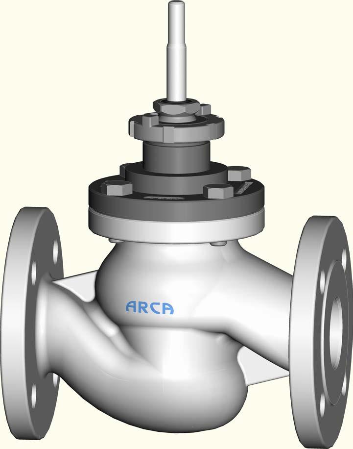
21 ARCA Regler GmbH 7 Functional description 7 Functional description Valves from this series are usually used as actuators within the meaning of DIN IEC The valve serves to reduce the pressure and quantity of a flow of medium through the plug. The flow of medium through the seat (20) is regulated by the position of the plug (26). The plug (26) is adjusted with the aid of an attached actuator, which acts on the Stem (50) connected to the plug (26) Illustration 11: Sectional drawing Series 8C / / 38
22 8 Fitting ARCA Regler GmbH 8 Fitting Place of installation The valve should be easily accessible from at least one side. Include a catwalk or similar in the planning in case of greater heights. An electric crane or block and tackle should be provided, depending on the weight. The valve is equipped with flanges or welded ends. After removal of the protective caps from the inlet and outlet sealing surfaces, valves with flanges are installed in the pipeline using gaskets and bolts provided by the customer. Valves with welded ends are welded into the pipeline. Please note: CAUTION Installation position Pipeline must be horizontal Actuator above the valve Pay attention to the flow direction arrow on the housing flange In case of a different installation position, special measures need to be taken to support the weight of the actuator! Forces from the pipeline must not be transmitted to the valve. A straight section of pipe with a length of at least 10x the nominal diameter must be provided for in front of and behind the valve. Built-in parts and branches are not permitted. A bypass line is recommended with shut-off valves before and after the valve. It recommended to install a dirt trap / filter before the valve. Attachment of an actuator The valve enables the attachment of different actuators. Various mounting kits and couplings are available for this. The actuator must be mounted according to the actuator manufacturer's operating manual. The maximum permissible actuating forces must be observed. DN Stem thread Max. actuating force [kn] ½ - 2½ M M18x CAUTION The following must additionally be observed when constructing an electric or hydraulic actuator: Switch-off in the closing direction via torque switch Switch-off in the opening direction via displacement switch 22 / / 1.1 Series 8C
23 ARCA Regler GmbH 9 Commissioning / Decommissioning 9 Commissioning / Decommissioning Before the initial commissioning Rinsing with rinsing set Rinsing with spacer Commissioning Decommissioning The valve remains installed The valve is removed In order to avoid damage to the trim due to possible existing contamination in the piping network, the piping network must be cleaned by rinsing and if necessary pickling. The following procedures are recommended: A rinsing set and rinsing flange(s) is mounted in place of the trim. Completely dismantle the valve so that only the housing remains in the pipeline Mount the rinsing set in place of the seat (to be ordered separately) Mount the rinsing flange(s) (to be ordered separately) Rinse and if necessary pickle Dismount the rinsing set and the rinsing flange(s) Clean the valve and replace the seal(s) Mount the trim and completely reassemble the valve A spacer is installed in the pipeline in place of the valve Remove the valve from the pipeline (flange-mounted valves only) Install the spacer in the pipeline Rinse and if necessary pickle Remove the spacer from the pipeline again Replace the seals Install the valve in the pipeline again Pay attention to the chapter entitled [2] Safety Avoid thermal shocks Bring the valve slowly up to operating temperature At a temperature difference of 300 K or more, the speed of temperature change must be restricted to max. 2 K/min. Check the flange connections for leaks Tighten the bolted connections diagonally. Refer to the chapter entitled [12] Torque tables for the tightening torques Check the stem sealing for leaks See the chapter entitled [10.3] Stem seal Detail X for this We recommend the following procedure for taking the valve out of service: In case of lengthy standstills, the valve and the pipeline must be emptied and rinsed, depending on the operating medium. Pay attention to the chapter entitled [2] Safety Remove the valve from the pipeline Treat the interior of the housing with a suitable preservative and seal the openings with suitable caps Series 8C / / 38
24 9 Commissioning / Decommissioning ARCA Regler GmbH To protect against corrosion, treat all unpainted parts and surfaces made of materials that are not rustproof with a suitable preservative Recommissioning NOTICE! All seals must be replaced if the valve has been out of service for more than one year. Mount the valve in accordance with the chapter entitled [8] Fitting Carry out the work according to the chapter entitled [10.1] Care Commission the valve according to the chapter entitled [9] Commissioning 24 / / 1.1 Series 8C
25 ARCA Regler GmbH 10 Maintenance 10 Maintenance 10.1 Care Clean the stem (50) if necessary 10.2 Maintenance Clean the stem (50) of adhering dirt using a soft cloth NOTICE! Never use sandpaper, since this will damage the surface of the stem and reduce the lifetime of the stem sealing. The valve is for the most part maintenance-free. Nevertheless, the flange connections and the stuffing box seal must be checked regularly for leaks. If necessary the work is to be carried out in accordance with the chapter entitled [9] Commissioning. Depending on the operating conditions of the valve, the operator is responsible for defining appropriate checking and maintenance intervals Stem seal Detail X NOTICE In general we wish to point out that all types of stuffing box seals are subject to wear due to the respective operating conditions and must be inspected and if necessary replaced at regular intervals. Stuffing box seal with V-collar Stuffing box seal with packing rings Stuffing box seal with shaped ring Addition of packing rings The stuffing box seal with V-collar is not adjustable. In case of leaks the entire seal set must be exchanged. The stuffing box seal with packing rings is adjustable. The stuffing box screw (152) can be tightened if the stuffing box seal should leak. The stuffing box screw should only be tightened to the extent that the force of the actuator still allows jerk-free movement of the stem (50). If the stuffing box screw (152) is tightened too much and the stem (50) jams or jerks, the stuffing box screw (152) must be loosened again until jerk-free operation is possible. Nevertheless, the sealing integrity must still be guaranteed. Packing rings can be added if no further tightening of the stuffing box screw (152) is possible. See section entitled Addition of packing rings. The stuffing box seal with shaped ring is not adjustable. In case of leaks the entire seal set must be exchanged. Split packing rings can be temporarily added. However, an exchange of the complete stuffing box seal should take place as soon as possible. Pay attention to the chapter entitled [2] Safety WARNING! Drive the actuator to the upper end position and secure it Unscrew and remove the stuffing box screw (152) Series 8C / / 38
26 10 Maintenance ARCA Regler GmbH Carry out the work according to the chapter entitled [10.1] Care Insert a split packing ring Fit the stuffing box screw (152) Commission the valve according to the chapter entitled [9] Commissioning Stuffing box chamber sleeve In order to prevent corrosion of the stuffing box chamber, a sleeve (169) made of stainless steel is inserted in the case of bonnets made of materials that are not rustproof V-collars V-collars Illustration 12: V-collars 117 * Wiper ring 152 Stuffing box screw 156 * Seal set 164 * Plain bearing 166 * O-ring 168 * Sealing 169 Sleeve V-collars vacuum operation Illustration 13: V-collars vacuum operation 117 * Wiper ring 152 Stuffing box screw 156 * Seal set 164 * Plain bearing 166 * O-ring 168 * Sealing 169 Sleeve 26 / / 1.1 Series 8C

27 ARCA Regler GmbH 10 Maintenance Packing rings Packing rings 117 * Wiper ring 152 Stuffing box screw 154 * Base ring 156 * Seal set 164 * Plain bearing 168 * Sealing 169 Sleeve Illustration 14: Packing rings Shaped ring Double quad ring 117 * Wiper ring 152 Stuffing box screw 156 * Seal set 164 * Plain bearing 168 * Sealing 169 Sleeve Illustration 15: Double quad ring Variseal ring 117 * Wiper ring 152 Stuffing box screw 154 * Base ring 164 * Plain bearing 168 * Sealing 169 Sleeve 356 * Sealing element Illustration 16: Variseal ring Series 8C / / 38
28 11 Disassembly / assembly of the valve ARCA Regler GmbH 11 Disassembly / assembly of the valve WARNING Disregarding the safety instructions Risk of injury! Observe the notes in the chapter entitled [2] Safety 11.1 Procedure 11.2 Actuator 11.3 Bonnet Disassembly of the valve. Dismounted parts are to be secured carefully against falling down (risk of injury or damage). Clean all components. Assembly in the reverse order using the new components. Seals and packings are generally to be replaced. Insert any existing dynamically loaded O-rings and shaped rings using a suitable lubricant, provided that the process conditions allow. Refer to the chapter entitled [12] Torque tables for the tightening torques of bolted connections. Following assembly, the plug must be moved to the upper and lower end positions by hand or using auxiliary energy. The plug may neither jerk nor scrape when doing this. If necessary the bonnet connections must be loosened, the components re-aligned to one another and the connections tightened again. Then commission the valve according to the chapter entitled [9] Commissioning. WARNING! Drive the actuator to the central stroke position and secure it. Decouple and remove the actuator. Follow the actuator manufacturer's mounting instructions! Standard/cooling fins/ insulating column versions down to -196 C Unscrew the stuffing box screw (152) Refer also to the chapter entitled [10.3] Stem sealing Detail X for this Release the bolted connection between the housing (1) and the bonnet (2) Lift off the bonnet (2) CAUTION! The plug (26) may be lifted off with the bonnet (2) Pull the plug (26) out of the bonnet (2) Do not bend the stem (50) 28 / / 1.1 Series 8C
29 ARCA Regler GmbH 11 Disassembly / assembly of the valve Bellows/insulating column versions down to -50 C Unscrew the stuffing box screw (152) Refer also to the chapter entitled [10.3] Stem sealing Detail X for this Release the bolted connection between the bonnet (2) and the intermediate flange (6) Lift off the bonnet (2) CAUTION! Do not bend the stem (50)! 11.4 Stem sealing V-collars Remove the seal set (156) consisting of V-collar, support disc and spring Refer also to the chapter entitled [10.3] Stem sealing Detail X for this Packing rings Remove the sealing set (156) and the base ring (154) Refer also to the chapter entitled [10.3] Stem sealing Detail X for this 11.5 Plain bearing Remove the plain bearing (164) from the stuffing box screw (152) NOTICE! Observe the following when mounting the plain bearing (164): Coated side towards the stem (50) Fabric side towards the stuffing box screw (152) 11.6 Intermediate flange (version with bellows) Release the bolted connection between the housing (1) and the intermediate flange (6) Lift off the intermediate flange (6) with bellows (142) and plug (26) CAUTION! Do not bend or damage the stem (50)! 11.7 Cylinder tube (version with balancing system) 11.8 Plug Pull out the cylinder tube (60) Depending on the size and version, use a mounting thread and if necessary lifting equipment Depending on the version the plug (26) has already been dismantled. Standard Pull the plug (26) with the stem (50) out of the housing (1) Version with bellows The plug can be exchanged only in connection with new bellows (142). However, the bellows (142) can be exchanged without a new plug (26). Series 8C / / 38
30 11 Disassembly / assembly of the valve ARCA Regler GmbH Refer also to the chapter entitled [11.9] Stem version with bellows for this Stem Standard The stem (50) can only be exchanged complete with the plug (26). Illustration 17: Plug/stem fastening standard Example illustration with parabolic plug 26 * Plug (compl.) 50 * Stem Version with bellows The stem can only be exchanged complete with bellows unit (142). Remove the clamping sleeve (51) To do this, compress the bellows unit (142) with the help of the stem (50) Unscrew the plug (26) CAUTION! The bellows unit (142) must not be subjected to twisting forces! Replace the seal (140) Insert the new stem (50) with bellows (142) into the intermediate flange (6), screw on the plug (26) and drill 30 / / 1.1 Series 8C
 50 * Stem 51 * Clamping sleeve 140 * Sealing 142 * Bellows unit Illustration 18: Plug/stem fastening - bellows Example illustration with parabolic plug Version with insulating column The stem (50)")
 Unscrew and remove the stem (50) and exchange it Screw the new stem (50) to the plug (26) and drill Drive in the clamping sleeve (51) 26 * Plug (compl.")
31 ARCA Regler GmbH 11 Disassembly / assembly of the valve Drive in the clamping sleeve (51) 6 Intermediate flange 26 * Plug (compl.) 50 * Stem 51 * Clamping sleeve 140 * Sealing 142 * Bellows unit Illustration 18: Plug/stem fastening - bellows Example illustration with parabolic plug Version with insulating column The stem (50) can be exchanged. Remove the clamping sleeve (51) Unscrew and remove the stem (50) and exchange it Screw the new stem (50) to the plug (26) and drill Drive in the clamping sleeve (51) 26 * Plug (compl.) 50 * Stem 51 * Clamping sleeve Illustration 19: Plug/stem fastening insulating column Example illustration with parabolic plug Version with balancing system The stem (50) can be exchanged. Unscrew and remove the hex nut (57) and replace it Series 8C / / 38
 Illustration 20: Plug/stem fastening balancing system Example illustration with perforated plug 26 * Plug (compl.")
 Quad ring Exchange the sealing element (198) and support rings")
 using a piston ring expander 177 * Piston ring Illustration 22: Balancing seal piston rings Detail Z")
32 11 Disassembly / assembly of the valve ARCA Regler GmbH Take off and replace lock washer (59) Pull the stem (50) out of the plug (26) Illustration 20: Plug/stem fastening balancing system Example illustration with perforated plug 26 * Plug (compl.) 50 * Stem 57 * Hex nut 59 * Lock washer Balancing seal - Detail Z (version with balancing system) Quad ring Exchange the sealing element (198) and support rings (199) Illustration 21: Balancing seal quad ring Detail Z 198 * Sealing element 199 * Support ring Piston rings Dismount the piston rings (177) using a piston ring expander 177 * Piston ring Illustration 22: Balancing seal piston rings Detail Z Variseal ring Fig. 0.1 Exchange sealing element (198) 32 / / 1.1 Series 8C


33 ARCA Regler GmbH 11 Disassembly / assembly of the valve NOTICE! Warm up the sealing element in a water bath before assembly. Illustration 23: Balancing seal Variseal ring Fig. 0.1 Detail Z 198 * Sealing element Variseal ring Fig. 0.2 Unscrew and remove the screw (173) of the stuffing box gland (170) Remove the stuffing box gland (170) Exchange sealing element (198) Illustration 24: Balancing seal Variseal ring Fig. 0.2 Detail Z 170 Stuffing box gland 172 * Screw 198 * Sealing element Retainer & seat Standard Take the retainer (182) and seat (20) out of the housing (1) Exchange sealing element (180) Version with soft seal Detail Y Flat gasket & O-ring Take the retainer (182), clamping ring (181) and complete seat (20, 183, 184) out of the housing (1) Replace the sealing element (184) and O-ring (183) Exchange sealing element (180) Illustration 25: Soft seal, flat gasket & O-ring Detail Y Example illustration with parabolic plug 20 * Seat 180 * Sealing element 181 Clamping ring 182 Retainer 183 * O-ring 184 * Sealing element Series 8C / / 38
 Illustration 26: Soft seal, trapezoidal ring Detail Y Example illustration with parabolic plug 20 * Seat 180 * Sealing element 181 Clamping ring 182 Retainer 184 *")
34 11 Disassembly / assembly of the valve ARCA Regler GmbH Trapezoidal ring Take the retainer (182), clamping ring (181) and complete seat (20, 184) out of the housing (1) Exchange sealing element (184) Exchange sealing element (180) Illustration 26: Soft seal, trapezoidal ring Detail Y Example illustration with parabolic plug 20 * Seat 180 * Sealing element 181 Clamping ring 182 Retainer 184 * Sealing element 34 / / 1.1 Series 8C
35 ARCA Regler GmbH 12 Torque tables - bolted connections 12 Torque tables - bolted connections 12.1 Screws according to DIN EN ISO 4017/4014, DIN 939 Thread Torque [Nm] A2-70 M8 13 M10 30 M12 50 M M M M Screws according to DIN 2510 Thread Torque [Nm] A M10 * M M M M M M M M M * Works standard 12.3 Screws according to ASME B16.5 Thread Torque [Nm/lbf ft] A193B7 A193B8 A193B7M ½ -UNC 19/14 46/34 73/54 ⅝ -UNC 35/26 90/66 140/103 ¾ -UNC 50/37 150/ /184 ⅞ -UNC 90/66 250/ / UNC 170/ / /443 1⅛ -UNC 280/ / /620 1¼ -UNC 990/ / /885 Series 8C / / 38
36 13 Fault removal ARCA Regler GmbH 13 Fault removal WARNING Improper troubleshooting work on the valve Risk of injury! For all troubleshooting work on the valve, observe the corresponding notes in this operating manual or in the operating manuals for the additionally installed components. Please contact the manufacturer if problems occur that are not described in this table. Fault Possible causes Action No flow Valve closed Open the valve by means of the actuator Flange covers (transport protection) have not been removed Remove flange covers Inadequate flow Valve not opened sufficiently Open the valve by means of the actuator Stem moves jerkily Blockage in the piping system Incorrect valve or incorrect Kvs value selected Stuffing box screw overtightened (in case of valves with adjustable stem sealing) Stem or plug doesn't move Stuffing box screw overtightened (in case of valves with adjustable stem sealing) Seat and plug very dirty Due to contamination in the medium, the stem or plug has eaten into its guide Check the pipeline Use valve with correct Kvs value Slacken off the stuffing box screw a little Sealing integrity must be maintained Slacken off the stuffing box screw a little Sealing integrity must be maintained Clean seat and plug Replace the stem, plug and guides Stem seal is leaking Stuffing box seal damaged or worn Replace sealing element Leakage rate too high in the closed state Stuffing box pretension too low (in case of valves with adjustable stem seal) Sealing edges on the plug and/or seat damaged Dirt/foreign bodies in the valve Balancing seal worn in balanced valves Tighten the stuffing box screw Rework or replace plug and/or seat Clean the interior of the valve, fit a dirt trap if necessary Replace sealing element Closing force of the actuator too low Use a more powerful actuator, Check the operating data 36 / / 1.1 Series 8C
37 ARCA Regler GmbH 14 Disposal and recycling 14 Disposal and recycling WARNING Operating media and auxiliary materials that are hazardous to health Danger to people and the environment! Wear suitable protective equipment If applicable, collect and dispose of rinsing medium or residual medium. Particular attention is to be paid to dead spaces (pressure compensation, bellows, etc.) Observe the legal regulations for the disposal of media that are hazardous to health ARCA products are modularly constructed and can be sorted by material into the following components. Electronic components Metals Plastics Greases and oils Packaging material The general rules are: greases and oils are usually water pollutants and must not be allowed to escape into the environment Dispose of dismantled materials properly or recycle the separate materials Observe national disposal regulations Series 8C / / 38
38
Operating and maintenance manual Control valve ECOTROL Series 6N/6H DN125/5"-DN400/16" / 1.0
 Operating and maintenance manual Control valve ECOTROL Series 6N/6H DN125/5"-DN400/16" 12.2017 / 1.0 Original instructions ARCA Regler GmbH. All rights reserved. Cover picture background: Freepik.com ARCA
Operating and maintenance manual Multi-spring actuator ARCAPAQ Series / 1.0
 Operating and maintenance manual Multi-spring actuator ARCAPAQ Series 812 03.2016 / 1.0 Original instructions ARCA Regler GmbH. All rights reserved. Cover picture background: Freepik.com ARCA Regler GmbH
Installation and operating manual Quick closing valve (Bellow sealed) LK product no:
 LK product no:") LK product no: 902002 Article no: 74506 Revision: 2 Contents 1. General information... 3 2. Safety precautions... 3 2.1 Significance of symbols... 3 2.2 Explanatory notes on safety information... 3 3.
LK product no: 902002 Article no: 74506 Revision: 2 Contents 1. General information... 3 2. Safety precautions... 3 2.1 Significance of symbols... 3 2.2 Explanatory notes on safety information... 3 3.
A408 GB. Pneumatic oil and diesel pumps 1:1
 03 594 A408 GB Pneumatic oil and diesel pumps 1:1 G Operating instructions for Pneumatic oil and diesel pump 1:1 Contents 1. General details 2 1.1 Intended use 2 1.2 Design and functional description 2
Globe Valve Type Fig. 1 Type 3241 Globe Valve. Mounting and Operating Instructions EB EN
 Globe Valve Type 3241 Fig. 1 Type 3241 Globe Valve Mounting and Operating Instructions EB 8015-1 EN Edition July 2012 Contents Contents Page 1 Design and principle of operation.................... 4 2
FLENDER ZAPEX couplings. Type ZWT. Operating instructions BA 3505 EN 10/2011. FLENDER couplings
 FLENDER ZAPEX couplings Type ZWT Operating instructions FLENDER couplings FLENDER ZAPEX couplings Type ZWT Operating instructions Translation of the original operating instructions Technical data Notes
Instructions for installation, operation and maintenance of: GATE VALVE
 Instructions for installation, operation and maintenance of: GATE VALVE GEN GAC GAF/GENF TERMOVENT SC Temerin Republic of Serbia Instruction for installation, operation and maintenance: Table of Contents
Installation and Operating Instructions
 Original Installation and Operating Instructions Hawle E2 Valve with Flange Outlet, System 2000 or PE Spigot Ends Table of Contents A) General...... 2 A1 Symbols..... 2 A2 Intended use... 2 A3 Labeling...
Operating and installation instructions
 Series 470 Series 471 Contents 1.0 General information on operating instructions...2-2 2.0 Notes on possible dangers...2-2 2.1 Significance of symbols... 2-2 2.2 Explanatory notes on safety information...
Pressure relief valve
 Pressure relief valve Operating manual Series DHV 712 Version BA-2015.10.20 EN Print-No. 300 510 TR MA DE Rev001 ASV Stübbe GmbH & Co. KG Hollwieser Straße 5 32602 Vlotho Germany Phone: +49 (0) 5733-799-0
Assembly and Maintenance Manual Type ASNU
 Assembly and Maintenance Manual Type ASNU Hatschekstr.36 69126 Heidelberg Germany Tel +49(0)6221 30470 Fax +49(0)6221 304731 info@stieber.de www.stieber.de Date of issue: 30.05.2018 GB Revision: 0 U:\EngUsers\!ProduktDoku\1AAA_Einbauerklaerung_Wartungsanleitung_Konformitaetserklaerung\1AAA_Wartungsanleitungen\Orginal_Worddatei\_ASNU.docx
Installation and operating manual
 LK product no: 901002 and 901102 501002 and 501102 (JIS) Article no: 74500 Revision: 9 Article no: 74500 Revision: 9 2 (23) Contents 1. General information... 5 2. Safety precautions... 5 2.1 Significance
Mounting and Operating Instructions EB 8135/8136 EN. Series V2001 Valves Type 3535 Three-way Valve for Heat Transfer Oil
 Series V2001 Valves Type 3535 Three-way Valve for Heat Transfer Oil Type 3535 Three-way Valve with bellows seal and rod-type yoke (partial view) Mounting and Operating Instructions EB 8135/8136 EN Edition
Installation, Operation, and Maintenance Manual
 Industrial Process Installation, Operation, and Maintenance Manual Series PBV Plastic Lined Ball Valve Table of Contents Table of Contents Introduction and Safety...2 Safety message levels...2 User health
Assembly and Maintenance Manual Type AS
 Assembly and Maintenance Manual Type AS Hatschekstr.36 69126 Heidelberg Germany Tel +49(0)6221 30470 Fax +49(0)6221 304731 info@stieber.de www.stieber.de Date of issue: 30.05.2018 GB Revision: 0 U:\EngUsers\!ProduktDoku\1AAA_Einbauerklaerung_Wartungsanleitung_Konformitaetserklaerung\1AAA_Wartungsanleitungen\Orginal_Worddatei\_AS.docx
Installation, Operation, and Maintenance Manual
 Industrial Process Installation, Operation, and Maintenance Manual Series PBFV Plastic Lined Butterfly Valve - Lug and Wafer Style Table of Contents Table of Contents Introduction and Safety...2 Safety
Instruction Manual. Sewage lifting station compli 300
 Instruction Manual Sewage lifting station compli 300 Safety instructions Areas of application Electrical connection Installation Servicing Technical data Appendix JUNG PUMPEN GmbH Industriestr. 4-6 33803
Operating and installation instructions
 Series 450 Series 451 Contents 1.0 General information on operating instructions...2-2 2.0 Notes on possible dangers...2-2 2.1 Significance of symbols... 2-2 2.2 Explanatory notes on safety information...
Bicolour level gauge. Type BU green/red. D-04-B EN-1 Edition 05/11
 Bicolour level gauge Type BU green/red D-04-B-16615-EN-1 Edition 05/11 -itable of contents- 1. Health and safety instructions 4-5 1.1 General health and safety instructions...4 1.2 Unit-specific safety
Mounting and Operating Instructions EB 8053 EN. Series 250 Type and Type Pneumatic Control Valves
 Series 250 Type 3252 1 and Type 3252 7 Pneumatic Control Valves Type 3252 High-pressure valve with Type 3277 Pneumatic Actuator and Type 3767 Electropneumatic Positioner Mounting and Operating Instructions
In combination with an actuator, e.g. a SAMSON Type 3271 or Type 3277 Pneumatic Actuator
 Type 3510 Micro-flow Valve In combination with an actuator, e.g. a SAMSON Type 3271 or Type 3277 Pneumatic Actuator DIN version Translation of original instructions Type 3510-1 (left) and Type 3510-7 (right)
ECOTROL. control valve
 ECOTROL control valve ECOTROL control valve Committed to perfection in every detail 2 Powerful valve actuator The pneumatic multi-spring 812 series actuator shown here is deployed in many applications
Company Standard Mounting Instructions for Type Valves with Type AT Actuator
 Mounting Instructions for Type 72 82-62 Valves with Type AT Actuator Introduction These installation instructions contain important information on the installation, functioning, maintenance and storage
Assembly and Maintenance Manual Type RSBW
 Assembly and Maintenance Manual Type RSBW Hatschekstr. 36 69126 Heidelberg Germany Tel +49(0)6221 30470 Tel +49(0)6221 304731 info@stieber.de www.stieber.de Stieber Clutch Date of issue: 16/03/2017 GB
CO 3-WAY PNEUMATIC VALVE INSTRUCTION MANUAL 2080
 CO 3-WAY PNEUMATIC VALVE INSTRUCTION MANUAL 2080 STI S.r.l has taken every care in collecting and verifying the documentation contained in this Instruction Manual. The information herein contained are
In combination with an actuator, e.g. a SAMSON Type 3271 or Type 3277 Pneumatic Actuator
 Type 3510 Micro-flow Valve In combination with an actuator, e.g. a SAMSON Type 3271 or Type 3277 Pneumatic Actuator ANSI version Translation of original instructions Type 3510-1 (left) and Type 3510-7
Angle seat valve with piston actuator VZXA-...-K
 Angle seat valve with piston actuator VZXA-...-K Festo AG & Co. KG Postfach 73726 Esslingen Germany +49 711 347-0 www.festo.com 3 Further information Accessories www.festo.com/catalogue Spare parts www.festo.com/spareparts
EN Operating manual. Motorised zone valve. Three-way, 22 mm & 28 mm 3PV2, 3PV8 & VRMH3
 EN Operating manual Motorised zone valve Three-way, 22 mm & 28 mm 3PV2, 3PV8 & VRMH3 This manual ensures safe and efficient use of the 3PV2 or 3PV8 force-actuated three-way valve with spring-loaded return
BW - BIG VOLUME BOOSTER INSTRUCTION MANUAL 2072
 BW - BIG VOLUME BOOSTER INSTRUCTION MANUAL 2072 STI S.r.l has taken every care in collecting and verifying the documentation contained in this Instruction Manual. The information herein contained are reserved
INSTRUCTIONS FOR INSTALLATION, OPERATION AND MAINTENANCE OF
 INSTRUCTIONS FOR INSTALLATION, OPERATION AND MAINTENANCE OF Lift Check Valves according to European Norms [CLEN] Table of Contents 1. General safety information s 3 2. Product description 3 3. Transport
Operating and installation instructions
 Strainer PN6-160 1.0 General information on operating instructions...2-2 2.0 Notes on possible dangers...2-2 2.1 Significance of symbols... 2-2 2.2 Explanatory notes on safety information... 2-2 3.0 Storage
Quick-Disconnect Coupling one-hand operation Push Pull ND 5, connecting thread G 1/4,max. operating pressure 500 bar
 Issue 12-2013 Quick-Disconnect Coupling one-hand operation Push Pull ND 5, connecting thread G 1/4,max. operating pressure 500 bar Figure 1: Coupling complete Figure 4: Coded coupling, complete Table of
Standard Valves Series Globe Valves Series Angle Valves Series Way-Valves
 Installation, Operation, Maintenance Instructions Standard Valves Series 035 000 Globe Valves Series 031 000 Angle Valves Series 033 000 3-Way-Valves 1 GENERAL INFORMATION These instructions are designed
Turbocharger / A100-L Original assembly instructions English
 Assembly Instructions Turbocharger / A100-L Original assembly instructions English This document is valid for the A100-L series: A165-L, A170-L, A175-L, A180-L, A185-L, A190-L Purpose The assembly instructions
Mounting and Operating Instructions EB 8039 EN. Type 3351 Pneumatic On/off Valve. Type 3351 Pneumatic On/off Valve. Type 3351 Pneumatic On/off Valve
 Type 3351 Pneumatic On/off Valve Type 3351 Pneumatic On/off Valve Type 3351 Pneumatic On/off Valve Version with handwheel Mounting and Operating Instructions EB 8039 EN Edition May 2016 Definition of signal
Operating and installation instructions
 DP30 DP32 DP33 DP34 Contents 1.0 General information on operating instructions... 2-2 2.0 Notes on possible dangers... 2-2 2.1 Significance of symbols... 2-2 2.2 Explanatory notes on safety information...
Operating & Maintenance Manual For Steam Conditioning Valve
 For Steam Conditioning Valve 1 Table of Contents 1.0 Introduction 3 2.0 Product description 3 3.0 Safety Instruction 4 4.0 Installation and Commissioning 5 5.0 Valve Disassembly 6 6.0 Maintenance 6 7.0
Pneumatic grease pump 50:1 and grease supply system
 Pneumatic grease pump 50:1 and grease supply system 03 591 A411 GB G Operating instructions for Pneumatic grease pump 50:1 Contents 1. General Information 2 1.1 Usage Stipulations 2 1.2 Construction &
These installation and maintenance instructions must be read in full and completely understood before the installation!
 These installation and maintenance instructions must be read in full and completely understood before the installation! 1. General information on the installation and maintenance instructions These instructions
Globe Control Valve Series 1a
 Maintenance Globe Control Valve Series 1a are subject to alteration without notice. The text and illustrations do not necessarily display the scope of supply or any ordering of spare parts. Drawings and
Accessories for Wind Power Inverter WINDY BOY PROTECTION BOX 400 / 500 / 600
 Accessories for Wind Power Inverter WINDY BOY PROTECTION BOX 400 / 500 / 600 Installation Guide WBP-Box-IEN103320 IMEN-WBP-BOX Version 2.0 EN SMA Solar Technology AG Table of Contents Table of Contents
Assembly and maintenance manual Type FSO, FSO-GR, FS, HPI
 Type FSO, FSO-GR, FS, HPI Hatschekstr.36 69126 Heidelberg Deutschland Tel +49(0)6221 30470 Fax +49(0)6221 304731 info@stieber.de www.stieber.de Date of issue: 23.08.2018 GB Revision: 0 U:\EngUsers\!ProduktDoku\1AAA_Einbauerklaerung_Wartungsanleitung_Konformitaetserklaerung\1AAA_Wartungsanleitungen\Orginal_Worddatei\M1124E_0_FSO_FSO-GR_FS_HPI.docx
USER INSTRUCTIONS. Kämmer SmallFlow / / SP Low and Micro Flow Valves. Installation Operation Maintenance
 User Instructions SmallFlow - KMENIM5000-02 02/15 USER INSTRUCTIONS Kämmer SmallFlow - 385000 / 385300 / 385000 SP Low and Micro Flow Valves FCD KMENIM5000-02 02/15 Installation Operation Maintenance Experience
KEYSTONE SERIES 320 BUTTERFLY VALVES INSTALLATION AND MAINTENANCE INSTRUCTIONS
 Before installation these instructions must be fully read and understood HAZARD POTENTIALS disregarding of instructions improper use of product insufficiently qualified personnel Valve application to be
Mounting and Operating Instructions EB 8091 EN. Pneumatic Control Valve Type and Type Type with 120 cm 2 actuator
 Pneumatic Control Valve Type 3510-1 and Type 3510-7 Type 3510-1 with 120 cm 2 actuator Type 3510-7 with 120 cm 2 actuator and integrated positioner Type 3510-1 with 60 cm 2 actuator Fig. 1 Pneumatic control
NEOTECHA NTB-NTC BALL VALVES INSTALLATION AND MAINTENANCE INSTRUCTIONS
 Before installation these instructions must be fully read and understood 2 SAFETY Please also read through these notes carefully. 2.1 General potential danger due to: a. Failure to observe the instructions
USER INSTRUCTIONS. Kämmer SmallFlow - Series / Low and Micro Flow Valves. Installation Operation Maintenance. Experience In Motion
 User Instructions SmallFlow 080/081000 - KMENIM8000-01 08/11 USER INSTRUCTIONS Kämmer SmallFlow - Series 080000 / 081000 Low and Micro Flow Valves FCD KMENIM8001-01 08/11 Installation Operation Maintenance
Turbocharger / TPS-H Original assembly instructions English
 Assembly Instructions Turbocharger / TPS-H Original assembly instructions English This document is valid for the TPS-H series: TPS44-H, TPS48-H, TPS52-H Purpose TPS-H turbocharger The assembly instructions
Mounting and operating instructions EB 8093 EN. Series 240 Pneumatic Control Valve for Cryogenic Temperatures. Type and
 Series 240 Pneumatic Control Valve for Cryogenic Temperatures Type 3248-1 and 3248-7 Fig. 1 Type 3248 Cryogenic Valve with Type 3277 Pneumatic Actuator as globe and angle valve Mounting and operating instructions
Mounting and Operating Instructions EB 8222 EN. Type 3310/AT and Type 3310/3278 Pneumatic Control Valves. Type 3310 Segmented Ball Valve
 Type 3310/AT and Type 3310/3278 Pneumatic Control Valves Type 3310 Segmented Ball Valve Fig. 1 Type 3310/3278 with positioner Fig. 2 Type 3310/AT Mounting and Operating Instructions EB 8222 EN Edition
Installation, Operation, and Maintenance Manual
 Industrial Process Installation, Operation, and Maintenance Manual Cam-Tite Ball Valve Table of Contents Table of Contents Introduction and Safety...2 Safety message levels...2 User health and safety...2
I & M Mark 78 Series. Ideal Installation. Start-Up. Installation & Maintenance Instructions for Mark 78 Control Valves (1-1/2-2 )
") I & M Mark 8 Series 0 Wasson Road Cincinnati, OH 4509 USA Phone 5-5-5600 Fax 5-8-005 info@richardsind.com www.jordanvalve.com Installation & Maintenance Instructions for Mark 8 Control Valves (-/ - ) Warning:
I & M Mark 8 Series 0 Wasson Road Cincinnati, OH 4509 USA Phone 5-5-5600 Fax 5-8-005 info@richardsind.com www.jordanvalve.com Installation & Maintenance Instructions for Mark 8 Control Valves (-/ - ) Warning:
Mounting and Operating Instructions EB EN. Type 3372 Electropneumatic Actuator. Actuator area: 120 and 350 cm² With Type 3725 Positioner
 Type 3372 Electropneumatic Actuator Actuator area: 120 and 350 cm² With Type 3725 Positioner Translation of original instructions Type 3372 with 120 cm² actuator area Type 3372 with 350 cm² actuator area
Operating and installation instructions
 Pneumatic actuators DP34 Tandem / DP34 Tridem DP34T Contents DP34Tri 1.0 General information on operating instructions...2-2 2.0 Notes on possible dangers...2-2 2.1 Significance of symbols...2-2 2.2 Explanatory
BIOVENT. Hygienic Valve
 BIOVENT BIOVENT Committed to perfection in every detail Powerful valve actuator BIOVENT control valves are usually combined with pneumatic multi-spring ARCAPAQ actuator type 813. Not only is it cost effective,
Angle seat valve with piston actuator VZXA-...-K
 Angle seat valve with piston actuator VZXA-...-K Instructions Operating (Translation of the original instructions) Festo AG & Co. KG Ruiter Straße 82 73734 Esslingen Germany +49 711 347-0 www.festo.com
I & M Mark 78 Series. Ideal Installation. Start-Up. Installation & Maintenance Instructions for Mark 78 Control Valves (1/2-1 )
") I & M Mark 8 Series 30 Wasson Road Cincinnati, OH 4509 USA Phone 53-533-5600 Fax 53-8-005 info@richardsind.com www.jordanvalve.com Installation & Maintenance Instructions for Mark 8 Control Valves (/ -
I & M Mark 8 Series 30 Wasson Road Cincinnati, OH 4509 USA Phone 53-533-5600 Fax 53-8-005 info@richardsind.com www.jordanvalve.com Installation & Maintenance Instructions for Mark 8 Control Valves (/ -
KLINGER Piston Valves KVN DN PN 16 I/III with valve ring KX-GT Modul
 Page 1 Assembly Instructions and Handling Regulations for KLINGER Piston Valves KVN DN 65 150 PN 16 I/III with valve ring KX-GT Modul DN 125-150 1 Body 2 Bonnet 3 Hand wheel 4 Piston 5 Lantern bush 8 Threaded
Butterfly valves Figure 56 Installation & Maintenance Instructions
 KEYSTONE Please read these instructions carefully This symbol indicates important messages and safety instructions. Hazard potentials: disregarding of instructions improper use of product insufficiently
Instructions for installation, operation and maintenance of: SWING CHECK VALVE CSEN CSBS CAPS CSWEN CSWAPI. TERMOVENT SC Temerin Republic of Serbia
 Instructions for installation, operation and maintenance of: SWING CHECK VALVE CSEN CSBS CAPS CSWEN CSWAPI TERMOVENT SC Temerin Republic of Serbia Table of Contents 1. General safety information s... 3
Mounting and Operating Instructions EB 8097 EN. Pneumatic Control Valves Type and Type
 Pneumatic Control Valves Type 3347-1 and Type 3347-7 Hollow-mold cast body with welding ends Full-mold cast body with threaded connections Fig. 1 Type 3347-7 Control Valve with Type 3277 Actuator and integral
Operating manual Separator
 Operating manual Separator Sheet no. AS/4.1.141.1.1 issue 20.08.2014 Contents Section Title Page 0 Introduction... 1 1 Intended use......1 2 Marking of the fitting... 1 3 Safety instructions... 2 4 Transport
Water level controller and limiter
 Water level controller and limiter RBJ 54 RBJ 64(63) D-07-B-16632-EN-0 Edition 10/09 -i Table of contents- 1. Health and safety instructions 4-5 1.1 General health and safety instructions...4 1.2 Unit-specific
Mounting and Operating Instructions EB 8256 EN. Type 3286 Steam Conditioning Valve
 Type 3286 Steam Conditioning Valve In combination with an actuator, e.g. a SAMSON Type 3271 or Type 3277 Pneumatic Actuator DIN version Translation of original instructions Mounting and Operating Instructions
Type 3571 Pneumatic Actuator. Actuator areas: 27 in² 54 in² 116 in². Original instructions. Mounting and Operating Instructions EB 8820 EN
 Type 3571 Pneumatic Actuator Actuator areas: 27 in² 54 in² 116 in² Original instructions Mounting and Operating Instructions Edition April 2016 Note on these mounting and operating instructions These mounting
Instructions for Use Plain Trolley ULK Geared Trolley UHK
 Instructions for Use Plain Trolley Geared Trolley Item no. Load-carrying capacity (payload) Weight Trolley widths *special trolley widths* Device dimensions mm H / W / D Minimum curve radius mm -005 0,5
Mounting and Operating Instructions EB 8111/8112 EN. Series V2001 Valves Type 3321 Globe Valve
 Series V2001 Valves Type 3321 Globe Valve Type 3321 Globe Valve with rod-type yoke and Type 3372 Electropneumatic Actuator (350 cm²) Mounting and Operating Instructions EB 8111/8112 EN Edition June 2013
Installation and Operating Manual for Tank and Equipment Cleaning Nozzles Series 5TM
 Installation and Operating Manual for Tank and Equipment Cleaning Nozzles Series 5TM 150 150 150 This instruction manual contains proprietary information which is protected by copyright laws. No part of
Mounting and Operating Instructions EB 8111/8112 EN. Valve Series V2001 Globe Valve Type 3321
 Valve Series V2001 Globe Valve Type 3321 Fig. 1 Type 3321 Valve with mounted rod-type yoke for pneumatic or electric actuators (partial view) Mounting and Operating Instructions EB 8111/8112 EN Edition
KEYSTONE. Butterfly valves Figure 9 Installation & Maintenance Instructions. Please read these instructions carefully
 KEYSTONE Please read these instructions carefully This symbol indicates important messages and safety instructions. Hazard potentials: disregarding of instructions improper use of product insufficiently
Installation manual wall-mounted distributor
 EN Installation manual wall-mounted distributor EN 60003233 Issue 11.2016 2016-14-11 Table of contents 1 About this manual 3 1.1 Structure of the warnings 3 1.2 Symbols used 4 1.3 Signal words used 4 2
Mounting and Operating Instructions EB 5868/5869 EN
 Electric Control Valves Types 3213/5857, 3213/5824, Types 3214/5824, 3214/3374, 3214/3274 with safety function: Types 3213/5825, 3214/5825, 3214/3374, 3214/3274 Pneumatic Control Valves Types 3213/2780-1,
Angle seat valve with diaphragm actuator VZXA-...-M
 Angle seat valve with diaphragm actuator VZXA-...-M Instructions Operating (Translation of the original instructions) Festo AG & Co. KG Ruiter Straße 82 73734 Esslingen Germany +49 711 347-0 www.festo.com
Split Body Valves with Bellows Seal Series Globe Valves Series Angle Valves Series Way-Valves
 Installation, Operation, Maintenance Instructions Split Body Valves with Bellows Seal Series 025 300 Globe Valves Series 027 300 Angle Valves Series 028 300 3-Way-Valves 1 GENERAL INFORMATION These instructions
Swing Piston Compressors and Vacuum Pumps
 Swing Piston Compressors and Vacuum Pumps NPK 018 AC Pressure NPK 018 DC Pressure NPK 018 AC Vacuum NPK 018 DC Vacuum Operating and Installation Instructions Read and observe these Operating and Installation
Mounting and Operating Instructions EB 8097 EN. Type and Type Pneumatic Control Valves
 Type 3347-1 and Type 3347-7 Pneumatic Control Valves Type 3347-7, cast body with welding ends Type 3347-7, bar stock body with threaded connections Mounting and Operating Instructions EB 8097 EN Edition
In combination with an actuator, e.g. a SAMSON Type 3271 or Type 3277 Pneumatic Actuator
 Type 3244 Valve In combination with an actuator, e.g. a SAMSON Type 3271 or Type 3277 Pneumatic Actuator DIN and ANSI versions Translation of original instructions Type 3244 Valve with Type 3271 Actuator
DIAPHRAGM LIQUID PUMP NF 2.35
 DIAPHRAGM LIQUID PUMP NF 2.35 NF 2.35 XP DC 24V Supply voltage [Ch. 4] DCB-A XP / XT [Ch. 4] 2.35 NF - / PMLxxxx / PLxxxx [Ch. 1] Operating and Installation Instructions Read and observe these Operating
Declaration of Conformity as per Directive 97/23/EC
 Declaration of Conformity as per Directive 97/23/EC The manufacturer declares that:, 47906 Kempen, Germany PTFE-lined Rotary plug valves Series 23e, with packing with lever for 90 operation with worm gear
Turbocharger / TPL-B Original assembly instructions English
 Assembly Instructions Turbocharger / TPL-B Original assembly instructions English This document is valid for the TPL-B series: TPL85-B14/15/16, TPL91-B Purpose The assembly instructions explain how the
T R A N S L A T I O N Declaration of Conformity as per Directive 2014/68/EU
 T R A N S L A T I O N Declaration of Conformity as per Directive 2014/68/EU The manufacturer declares that: Pfeiffer Chemie-Armaturenbau GmbH, 47906 Kempen, Germany Butterfly valves BR14a, BR14b, BR14b-Type
Keystone Butterfly valves ParaSeal Installation and maintenance instructions
 Before installation these instructions must be fully read and understood Please read these instructions carefully Hazard potentials: disregarding of instructions improper use of product insufficiently
DIAPHRAGM LIQUID PUMP NF 1.30
 DIAPHRAGM LIQUID PUMP NF 1.30 NF 1.30 KT DCG 12V Supply voltage [Ch. 4] DCG KT / TT [Ch. 4] 1.30 NF - / PMLxxxx / PLxxxx [Ch. 1] Operating and Installation Instructions Read and observe these Operating
Series 250 Pneumatic Control Valves Type and
 Series 250 Pneumatic Control Valves Type 3252-1 and 3252-7 Fig. 1 Type 3252 High-pressure Valve with Type 3277 Pneumatic Actuator and Type 3767 i/p Positioner Edition November 1998 Mounting and operating
original operating manual Operating manual Translation of the Item-No.: ,
 Translation of the original operating manual Operating manual Item-No.: 015 431 551, 015 431 581 Important! Copyright The operating manual is always to be read before commissioning the equipment. No warranty
Keystone Series GR resilient seated butterfly valves GRW/GRL Installation and operation manual
 Before installation these instructions must be fully read and understood Important Before valves are installed or used the following actions are recommended. 1. Valves/parts have to be inspected and thoroughly
Quarter turn actuator DAPS..R..-F..
 Quarter turn actuator DAPS..R..-F.. Festo AG & Co. KG Postfach D-73726 Esslingen +49 711 347-0 www.festo.com (en) Operating instructions 8030408 1309g [8030416] Original: de Quarter turn actuator DAPS..R..-F.....
ON SAFEGUARD S ON SAFEGUARD M
 instructions Retrofit option GB ON SAFEGUARD S ON SAFEGUARD M Insulating protective cover Observe additional system documents! General instructions CAUTION Read the operating instructions! The operating
Hook-in coupling n.b EH EH Operating Instruction English
 Revision A Datum 10.05.2013 Ersteller NH This operating instruction is not subject to the updating Hook-in coupling n.b. 25 1-EH-025-1-..-..-. 1-EH-025-4-..-.. 1 This coupling is a quality product, in
Operating Instructions
 Operating Instructions Quadax Series Butterfly Valves (with actuator) Version September 2009 müller co-ax ag Gottfried-Müller-Str. 1 74670 Forchtenberg Germany Tel. +49 7947 828-0 Fax +49 7947 828-11 E-Mail
Operating and Installation Instructions Swing Piston Compressors and Vacuum Pumps
 Operating and Installation Instructions Swing Piston Compressors and Vacuum Pumps UNPK04DC Pressure UNPK04DCB Pressure UNPK04DC Vacuum UNPK04DCB Vacuum KNF Neuberger, Inc 2 Black Forest Rd Trenton, NJ
KEYSTONE. Check valves Figure 85/86 Installation & Maintenance Instructions. Figure 85. Figure 86.
 KEYSTONE Please read these instructions carefully. This symbol indicates important messages and safety instructions. Hazard potentials: disregarding of instructions improper use of product insufficiently
Assembly Instructions and Handling Regulations for KLINGER. Piston Valves KVN DN VI,VIII and Regulating Piston KVRLN DN , PN 40 VI, VIII
 Page 1 Assembly Instructions and Handling Regulations for KLINGER Piston Valves KVN DN 65-200 VI,VIII and Regulating Piston KVRLN DN 65-200, PN 40 VI, VIII pressure released type with valve ring KX-GT
Storage, operating and maintenance instructions for AZ plug valves and Standard valves
 ARMATUREN Plug - Valves metallic with PTFE Sleeve 2-7 way Storage, operating and maintenance instructions for AZ plug valves and Standard valves Plug - Valves FEP/PFA - lined, 2-3 way Butterfly - Valves
FLENDER ARPEX Plate packs with close-fitting bolt connection. ARW-4 Sizes to Assembly instructions An 4239 en 12/2015.
 FLENDER ARPEX Plate packs with close-fitting bolt connection ARW-4 Sizes 101-4 to 292-4 Assembly instructions FLENDER couplings FLENDER ARPEX Plate packs with close-fitting bolt connection ARW-4 Sizes
Instruction Manual. Unique Single Seat Valve - Manually Operated ESE00523-EN Original manual TD TD
 Instruction Manual Unique Single Seat Valve - Manually Operated TD 461-583 TD 461-791 ESE00523-EN6 2016-07 Original manual Table of contents The information herein is correct at the time of issue but
Type Operating Instructions. Bedienungsanleitung Manuel d utilisation
 Globe control valve, pneumatically operated Actuator sizes 40 mm - 125 mm, Nominal diameter DN10-65 Kolbengesteuertes Geradsitzventil Antriebsgrößen 40 mm - 125 mm, Nennweiten DN10-65 Vanne à siège droit
Type Operating Instructions. Bedienungsanleitung Manuel d utilisation. 2/2-Way Solenoid Valve 2/2-Wege-Magnetventil Électrovanne à 2/2 voies
 Type 5282 2/2-Way Solenoid Valve 2/2-Wege-Magnetventil Électrovanne à 2/2 voies Operating Instructions Bedienungsanleitung Manuel d utilisation 1 OPERATING INSTRUCTIONS The operating instructions contain
Mounting and Operating Instructions EB 5894 EN. Electric control valves with jet pump. Flanged version of valve with jet pump
 Electric control valves with jet pump Type 3267/5824, Type 3267/5825, Type 3267/3374, Type 3267/3274 Pneumatic control valves with jet pump Type 3267-1, Type 3267-7 Flanged version of valve with jet pump
Keystone Figure 85/86 Check valves Installation and Maintenance Instructions
 Please read these instructions carefully 1.3 Handling 1.3.1 Packed valves Lifting and handling of the packed valves in crates should be carried out by appropriate lifting equipment. If a fork lift truck