Belt failure. Joseph Pandolfo PAPA 2016
|
|
|
- Shana Washington
- 6 years ago
- Views:
Transcription
1 Belt failure Joseph Pandolfo PAPA 2016
2 Squealing sound: Belt slipping Chirping sound: Misalignment of an accessory drive pulley Frayed belt edge: Misalignment of an accessory drive pulley Polished belt edges: Belt slipping Glazed belt grooves: Belt slipping Fluid contamination: Oil, power steering, or coolant leak Excessive cracking: Other than severe old age, defective tensioner
3 Whirring sound: defective bearing in tensioner pulley or idler pulley Rhythmic noises occurring at engine speed: Delaminating belt backing, chunking of belt ridges, or foreign object embedded in belt groove Grinding sound: damaged bearings in driven accessory Belt coming off: Pulley misalignment, belt misalignment on pulley, defective tensioner, or bearing wear in tensioner, idler or driven accessories
4 Belt noises can be diagnosed with a spray bottle of water. With the engine running and the sound audible, lightly mist the grooved side of the belt with water. If the noise disappears or lessens, but then shortly returns, the problem is probably a misaligned pulley. If the noise immediately increases after the belt is misted, the belt is slipping.
5 Another diagnostic trick is reversing the belt: take it off and put it back on so that it travels in what would have been its backward direction as originally installed. If the noise goes away or gets much softer, the problem is a misaligned pulley.
6 This diagnostic works because flipping the belt changes the direction of the misalignment from the belt s perspective. If reversing the belt does not temporarily eliminate the noise, the problem is something other than misaligned pulleys.
7 Glazing at the edges of a serpentine belt, or on its ridges or in the grooves, results from the belt slipping. It indicates that friction between the belt and the accessory drive pulley(s) created by slipping has overheated the belt.
8 Fraying at the edge of a belt indicates pulley misalignment. The edge frays because it is scraping on the top edge of an accessory drive pulley side as the belt feeds into it.
9 Fluid contamination attacks the rubber surface of the belt. All of the automotive fluids that can leak onto a belt oil, power steering fluid, coolant are petroleum based and will attack rubber. Once on the belt, any of these fluids will be distributed over the pulley groove surfaces, making them slippery and attracting dirt.
10
11 Normal Belt Wear and Failure A failure that occurs when a belt reaches its ultimate tensile cord fatigue life, after running for a period of two to three years may be considered to be normal. Belt tensile failure due to cord fatigue after a long running period is considered to be ideal.
12 Common Causes of Belt Failure Identifying the cause of belt failure can be challenging. In this section, we ll define, illustrate and diagnose some of the most common culprits, so you ll be prepared to correct the problem and take preventive measures in the future.

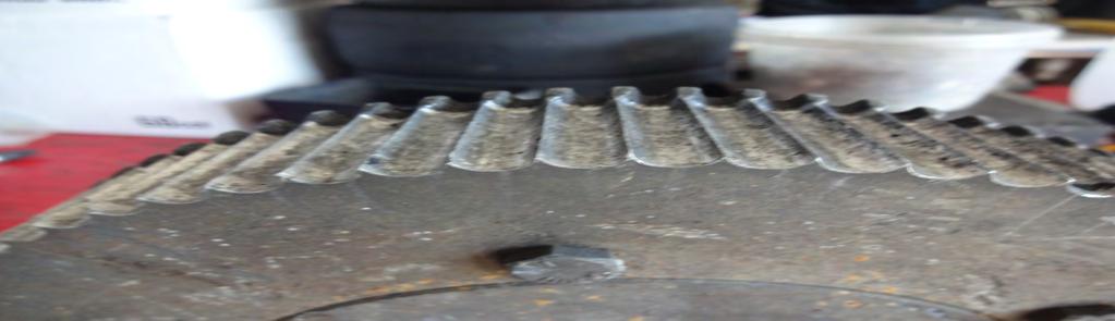
13 a jagged 45-degree belt fracture that is typical of tensile cord at the end of its fatigue life.

14 Synchronous belt teeth can also fail, but that is considered to be a non-ideal type of belt failure. After a long period of service, belt teeth may appear to be worn, although they should retain their original size and form. Protruding fibers from the jacket may give belt teeth a fuzzy appearance,

15 A crimp type belt failure often resembles a straight tensile failure A straight type of break like this may occur When belt tensile cords are bent around an excessively small diameter.
16 A sharp bend may result in large compressive forces within the tensile members causing individual fibers to buckle or crimp, reducing the overall ultimate tensile strength of the belt. Belt crimping damage Is most commonly associated with belt mishandling, inadequate belt installation tension, sub-minimal sprocket diameters, and/or entry of foreign objects within the belt drive.
17 Belt crimping due to mishandling can result from improper storage practices, improper packaging, and belt handling prior to and during installation.
18 Belts operating in an under tensioned condition may allow belt teeth to ride out of the sprockets until an acceptable belt tension level is achieved. This phenomenon is called self-tensioning. Self-tensioning can be most clearly observed at the point of lowest dynamic belt span tension, or where the belt teeth are entering the driven sprocket grooves.
19 When a belt is self-tensioning, the belt teeth ride up out of the sprocket grooves until increased span tension from the approaching tight side tension forces the belt teeth back down into the sprocket grooves. The point at which the belt teeth are forced back down into the sprocket grooves often results in a sharp, momentary point of bending that can result in belt tensile cord damage.
20 This point of tensile cord damage is referred to as a crimp. If the tight side tension does not force the belt teeth back down into the sprocket grooves, the belt will ratchet. Belt ratcheting can also result in tensile cord crimp and belt tooth damage.
21 Subjecting belts to sub-minimal bend diameters can also result in belt tensile cord damage, or crimping. This can be caused by sprockets or flat backside idlers in sub-minimal sizes, or even hand bending a belt too sharply
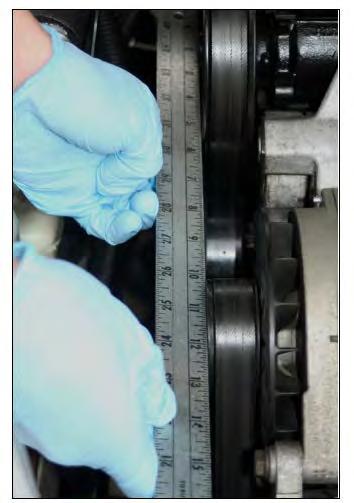
22 Foreign objects located between the belt and sprocket can also result in belt crimping. They can lift the belt away from the sprocket at a sharp angle, creating a point of tensile cord crimp. Tools used to force belts onto sprockets, such as screwdrivers or bars, can also cause belt cord crimp damage.
23
24 Shock Load Shock loading in belt drives occurs when higher than normal intermittent or cyclic torque loads are generated by the driven equipment. These shock loads result in higher than normal belt stresses and can act as a catalyst for belt failure.


25

26 root cracks caused by shock loading Can propagate through the teeth. Cracks forming at the tooth roots sometimes move towards the tooth tips. Teeth containing multiple cracks may then shear, leaving only a portion of the tooth behind.
27 The shock loads generated by the driven equipment may be an inherent part of system operation or may result from an occasional harsh condition such as jamming. If the drive shock loads cannot be eliminated, the belt tensile strength may need to be increased or the synchronous belt drive replaced with a more forgiving V-belt drive system capable of intermittent slip.
28 Improper Belt Installation Tension the effects of improper belt tensioning from applying excessive installation tension to insufficient tension to help prevent premature belt failure.
29 High Belt Installation Tension Applying excessive installation tension to a synchronous belt may result in belt tooth shear or even a tensile break. Many belts that have been excessively tensioned show visible signs that sprockets have worn the belt land areas.

30 a belt with crushed land areas and a crack that formed at the root of the belt tooth. A root crack will often propagate down to the tensile member and travel to the next root crack. Individual belt teeth will then separate from the body of the belt and often fall off.

31 a belt that had been over tensioned on large sprockets. High belt land pressures caused excessive belt land area wear, ultimately revealing individual tensile cords. In order to prevent belt wear problems like these, proper belt installation tension levels must be determined and set accurately.
32 Low Belt Installation Tension Applying insufficient installation tension to belts operating on moderately to heavily loaded drive systems may also result in premature failures. A common belt failure mode resulting from insufficient belt installation tension is referred to as tooth rotation. Belt tooth rotation can occur as belt teeth climb out of their respective sprocket grooves (self tensioning) and drive loads are no longer applied at their roots.
33 Drive loads applied further down the belt tooth flanks cause the belt teeth to bend (like a diving board) and rotate. Belt tooth rotation can result in rubber tearing at the base of the belt teeth along the tensile member. As rubber tearing propagates, belt teeth often begin to separate from the belt body in strips
34 Failures due to excessive tooth rotation may resemble failures caused by insufficient rubber adhesion to the tensile cords. Unlike tooth rotation failures, failures from insufficient rubber adhesion leave the exposed tensile members clean where the belt teeth were once located.
35 As belt teeth climb out of their respective sprocket grooves to self tension, belt ratcheting or tooth jumping may occur before rubber tearing and belt tooth separation occurs. Belt tensile cord damage resulting from ratcheting can cause premature belt tensile failures. These tensile failures may resemble crimp type breaks (straight and clean) as well as shock load type breaks (jagged and angled).

36 If belt ratcheting does not occur and belts continue to operate while self tensioning, excessive belt tooth wear often occurs. This tooth wear is referred to as hook wear and results from improper belt tooth meshing with the sprockets, Hook wear type belt failures result from insufficient belt installation tension and from weak drive structures that allow center distance flexing while the drive system is under load.
37 Increasing belt installation tension levels generally prevents premature belt failures due to tooth rotation and hook wear. If increasing the belt installation tension level does not prevent this type of failure, the drive structure may not be rigid enough to prevent deflection. Added structural support may be necessary to improve belt performance. If it is not practical to increase belt installation tension levels, increasing the sprocket diameters will allow higher drive loads to be transmitted With less belt tension.
38 Belt Drive Hardware Problems Let s examine the negative effects that problems with belt drive hardware have on the operation and life of your belts.
39 Sprocket Misalignment Belts operating on drives with angular shaft misalignment or tapered sprockets often exhibit an uneven wear pattern across the belt tooth flanks and uneven compaction in the land areas (in between belt teeth) due to the uneven application of load to the belt. Belt failures often occur from tooth root cracks or tears initiating on the side of the belt that is carrying the highest tension and propagating across the belt width, ultimately resulting in tooth shear.


40 One edge of the belt may also show significant wear due to high tracking force and may even roll up or attempt to climb the sprocket flange
41 Belts operating on flanged sprockets with parallel misalignment (off set sprockets) may exhibit excessive belt edge wear on both edges if the belt is pinched between opposite flanges. Belt failures may then occur by tooth root cracks or tears initiating from both edges of the belt. These tears may eventually extend across the entire width of the belt, resulting in tooth shear.
42 Belts operating on a combination of both flanged and nonflanged sprockets with parallel misalignment may walk or track partially off of the non-flanged sprocket(s). The portion of the belt remaining engaged with the non-flanged sprocket(s) will carry the full operating load and may develop a concentrated area of wear after running this way for a period of time.
43 shows concentrated wear across the majority of the belt tooth face with a portion relatively unworn. A root crack has also developed below the worn area. This may ultimately result in premature belt failure due to either tensile or tooth fatigue.
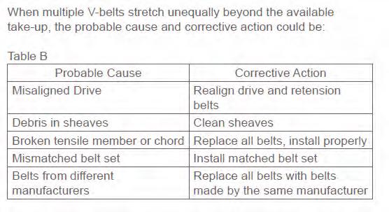
44 Sprocket(s) Out of Specification Premature belt failures resulting from sprockets either manufactured or worn outside of design specifications are difficult to recognize. This is partly due to the fact that sprockets are rarely inspected closely when a belt fails. Premature belt failures are often assumed to be the fault of the belt alone.


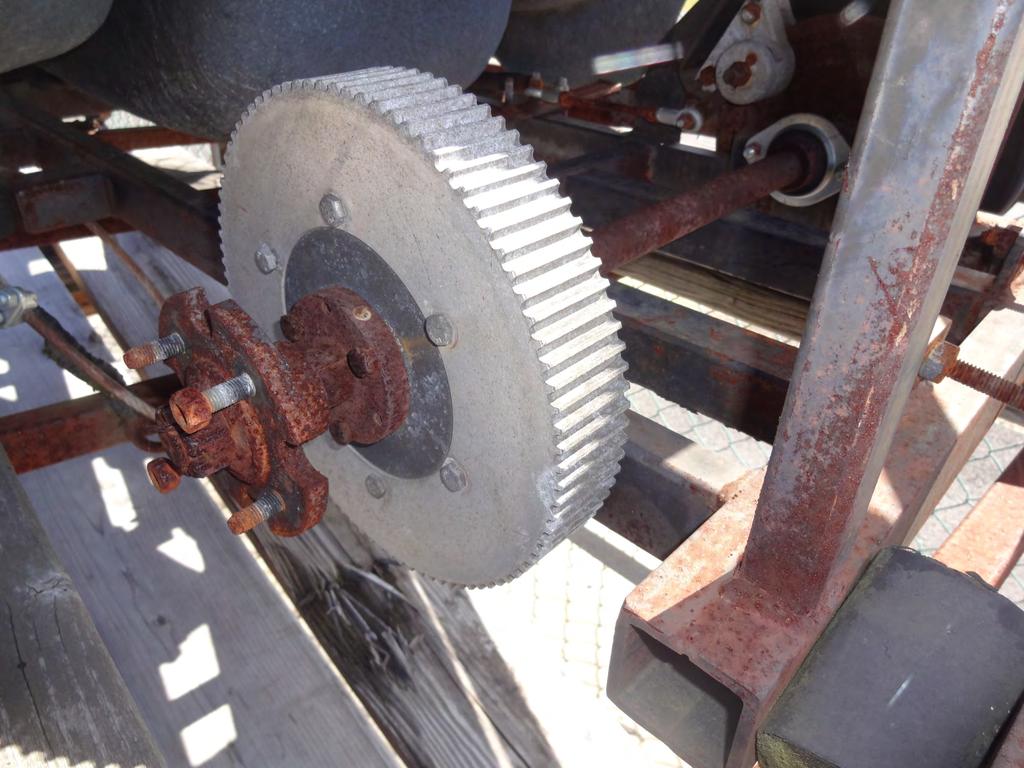
45 Belts operating on sprockets that are out of dimensional specification often show a high degree of tooth flank wear with the jacket flank exhibiting a fuzzy or flaking appearance,
46 A higher rate of sprocket wear may occur from belts that have been installed with excessive installation tension. Belts that have been in operation for a long time have sometimes had the tooth facing or Jacket completely worn away. Belts in this condition indicate that significant sprocket wear may have also occurred. Belts worn to this point also sometimes allow belt tensile members to contact the sprockets Resulting in a grooved wear pattern around the outside circumference.

47 Curvilinear (HTD and GT) belts operating on sub-minimal sprocket diameters usually fail by land disintegration, and tensile breaks. Trapezoidal (XL, L, H) belts will usually fail by tooth root cracks and tooth shear; however, tensile breaks are not uncommon.

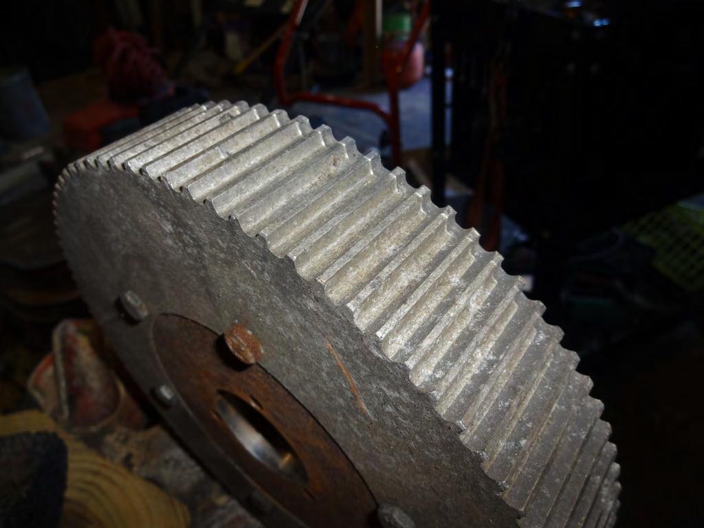
48 A good indication of sprocket wear is when a ridge along the tip of sprocket teeth becomes visible, Use caution: severely worn surfaces on sprocket faces may become very sharp. It is best to use a screwdriver or other tool to feel for the ridge in order to prevent finger cuts. When a ridge on the sprocket face is detected, the sprockets should be replaced.
49
50
51 The most rapidly and severely worn sprockets are most commonly found in abrasive atmospheres. Severely worn sprockets often exhibit groove wear as well as a reduction in the outside finish diameter. A typical belt failure on worn sprockets exhibits polished land wear and may have teeth worn to the point of serious dimensional distortion (hook wear). Sprockets plated with a hard chrome finish can be used to extend the sprocket life in abrasive atmospheres. Another indication of severe sprocket wear is when replacement belt life is noticeably reduced from previous belts. When this occurs, sprockets should be examined closely for excessive wear.

52 Belts subjected to significant cyclic peak tensions exhibit land areas with a crushed appearance. Crushed land areas and tooth shear are both visible in Extreme tooth wear from worn sprockets A crushed land area condition may appear similar to belts operating on moderate size sprockets under excessively high tensions. Belts subjected to extreme cyclic belt tension variations often fail from either tooth shear or tensile break.
53 Negative Effects of Environmental Conditions Looking at the environmental conditions abrasive atmosphere, heat degradation, chemical degradation, and foreign objects that can negatively impact your belts.

54 Abrasive Atmosphere Belts operating in abrasive atmospheres on applications like foundry shakers, taconite processing equipment, and phosphate mining conveyors often exhibit a high degree of belt land and tooth flank wear. Worn areas frequently have a polished appearance.
55 Heat Degradation When rubber belts operate at elevated temperatures (greater than 185 F) for prolonged periods of time, the rubber compound gradually hardens resulting in back cracking due to bending. These cracks typically remain parallel to the belt teeth and usually occur over land areas (in between belt teeth), Belts generally fail due to tooth shear, which often leads to tensile cord fracture.

56 High-temperature rubber belt constructions are available for belt drives that must operate in high-temperature environments. These special belt constructions help to improve belt service. The body material used in urethane belts such as Poly Chain GT Carbon belts is thermoplastic, meaning it has a melting point. When subjected to environmental temperatures in excess of 185 F, the teeth may begin to soften and deform.

57 Chemical Degradation Rubber belts subjected to either organic solvent vapors or ozone will resemble belts that have been subjected to high environmental temperatures. The rubber compound will harden and belts will exhibit back cracking. The cracking pattern will differ, though, in that the compound hardening occurs mostly at a surface level allowing cracks to form in both lateral and longitudinal directions. A checkered appearance may result.

58 Foreign Objects The introduction of foreign objects between a belt and sprocket often damages both belt teeth and tensile cords. Tensile cords often fracture internally or fail later due to crimping, Once a portion of the tensile cords have fractured, the remaining tensile strength of the belt has been reduced considerably.
59 How do you know if a V-belt is failing prematurely? By examining the clues. In the same way that physical symptoms in the body reflect an underlying disease, the physical signs on a V-belt and sheaves reflect underlying problems with the drive system. Finding and correcting the cause relieves the symptoms. The resulting benefits include: Better drive performance Longer belt life Improved drive efficiency Energy cost savings Reduced maintenance
60 What Is Normal Failure for a V-belt Drive?
61 The frequency of belt replacement depends on the speed, load, and hours of operation of the drive. This interval can vary significantly. The V-belt on a well maintained drive could deliver up to 3-5 years of service. In harsh conditions, the life of a belt might be reduced to one year or less.
62
63 This type of break can also occur for other reasons. The drive couldbe under-designed, subject to extreme or cyclical shock loading, or contaminated by debris. Or, the belt may have experienced damage to the tensile cords. Time is the key differentiator. If the belt is failing more often than expected, the cause is abnormal wear. If it fails in this manner after years of service, consider it normal failure.
64 Factors Affecting V-belt Life
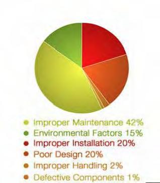
65 Improper Maintenance Poor maintenance is the major cause of premature V-belt failure. To transmit power efficiently, V-belts need a large surface area of contact, a high coefficient of friction (grip), and tension. A drive that has been properly designed for the application, installed correctly with new components, tensioned properly, and retensioned after a run-in period will meet these requirements. Time and neglect, however, can compromise these principles. Too much or too little tension, worn pulleys (sheaves) and misalignment are key indicators of improper maintenance.
66 Poor Design Poor drive design accounts for 20% of early V-belt failures. The drive may not have been designed properly for the original equipment. Or changes could have been made by the end user that increased the load or the speed of the equipment.
67 Improper Installation Another major cause that can lead to premature V-belt failure is improper installation. V-belt drive performance depends on applying and maintaining recommended installation tension levels. The ideal level is the lowest tension at which belts will not slip under peak loads. These levels are established by belt manufacturers and published in their design specifications.

68
69
70 Environmental Factors Excessive heat and contamination are two additional major causes of abnormal V-belt wear. The ideal operating temperature for a V-belt is approximately 140 F (60 C). Standard construction V-belts typically can withstand ambient temperatures up to 165 F (74 C) without sustaining appreciable damage. Gates V-belts with Ethylene construction are specified to go up to 230 F (110 C). Beyond these temperatures, every 18 F (8 C) increase in internal belt temperature can reduce V-belt service life by half.
71 Improper Handling and Defective Components There s a right and wrong way to store a V-belt until it is ready for use. Where possible, belts should be stored on a flat surface to avoid crimping. Hanging V-belts on hooks, especially large and heavy belts, can cause crimping and shorten life.
72 When mounting a V-belt, avoid prying or rolling the belt onto the sheave. Doing so can damage tensile cords and reduce belt life.

73

74 Always check sheaves for wear and damage before mounting a V-belt. Nicks and sharp edges can damage belts. So can worn sheaves. Using a plastic groove gauge is a simple method to check for wear If the clearance between the sheave and groove gauge exceeds 1/32 inch, replace the sheave.
75 Recognizing Problems A belt that squeals or chirps, makes a slapping, rubbing or grinding sound, or even an unusually loud drive is a sign of trouble.
76 So is unusual or excessive vibration or a belt flopping in the sheave. A belt that is hot to the touch is another warning sign. Further diagnosis involves inspecting the belt. Any sign of unusual wear points to a potential problem with the drive. Check for uneven wear patterns, cracking in the back, undercord or notches, frayed covers, burned spots, swelling and hardening.

77

78 Premature V-Belt Failure When a V-belt fails prematurely it may break delaminate, or slip to the point where it can t carry the load.

79 Another type of premature failure is edge cord failure due to sheave misalignment or a damaged tensile member. Correcting this problem involves checking and correcting the alignment, and following correct installation procedures when installing a new belt.
80 Severe or Abnormal V-Belt Wear When inspecting a V-belt, look at these locations for signs of unusual wear: Top surface Top corners Belt sidewalls Bottom corners Bottom surface Undercord cracking Sidewall burning or hardening Belt surface hard or stiff Belt surface flaking, sticky or swollen
81 Top surface wear might be caused by the belt rubbing against the guard, or by a malfunction of the idler. Check these locations, and repair or replace the guard and/or idler to correct the problem. Wear on the top corners of the belt may indicate that the belt is too small for the groove in the sheaves.

82 Excessive wear along the belt sidewalls could be caused by several factors. The belt could be slipping due to incorrect tension. If so, retention the drive until the slipping stops. Another potential problem is sheave misalignment, which requires realigning the drive. In this case, replace the sheaves. Or the belt may simply be the incorrect size and needs replacement with the correct size.

83 Wear on the bottom corners of the belt could be due to worn sheaves or an incorrect fit between belt and sheave. Check the sheaves for wear and replace them if necessary, or find the correct belt/sheave match.

84 Bottom surface belt wear could be caused by debris in the sheaves, sheave wear, or the belt bottoming out against the sheave grooves. Bottoming out is caused by an incorrect match between belt and sheave, and can be corrected by finding the proper match. If the sheaves are worn, replace them, and if debris has gotten into the sheaves, clean them.
85 Undercord cracking may be due to a number of factors. Environmental conditions (excessive heat or cold) or Improper storage could be to blame. Solutions involve controlling the belt drive environment and following proper storage and handling procedures. Another cause might be belt slip, corrected by retensioning the belt to the manufacturer s recommendations. A sheave that is too small for the belt section, causing the belt to wrap too tightly around the sheave, could crack the undercord. Replacing the small sheave with a larger one could correct the problem. Similarly, a backside idler with too small a diameter could be the problem, fixed by increasing the size of the backside idler.

86 Another cause might be belt slip, corrected by tensioning the belt to the manufacturer s recommendations. A sheave that is too small for the belt section, causing the belt to wrap too tightly around the sheave, could crack the undercord. Replacing the small sheave With a larger one could correct the problem. Similarly, a backside idler with too small a diameter could be the problem, fixed by increasing the size of the backside idler.

87 Sidewall burning or hardening is a sign of belt slip, worn sheaves, an under-designed drive or shaft movement. A slipping belt should be retensioned to the manufacturer s recommendations. A worn sheave should be replaced. If the drive is under-designed and can t carry the load, redesign it to the manufacturer s recommendations. Shaft movement might be caused by changes in the center distance between the sheaves, and should be checked and adjusted.

88 If the belt surface is hard or stiff it might be due to an excessively hot environment or to belt slip. Correct the problem by providing more ventilation to the drive or adjusting belt tension.

89 A belt surface that is flaking, sticky or swollen may have become contaminated by oil or chemicals. Eliminate the source of the contamination, and never use belt dressing.
90 Banded (Joined) V-Belt Problems (multiple belts with a common cover that serves as a tie-band) may exhibit signs that point to a drive problem. The following symptoms call for investigation: Tie-band separation Top of tie-band frayed, worn or damaged Banded belt comes off sheaves repeatedly One or more belt ribs run outside the sheave

91 Tie-band separation might be the result of improper groove spacing. Check the sheaves to ensure that they have been manufactured to industry specifications. Another cause might be worn or incorrect sheaves, which requires replacing the sheaves. Also check to see if the sheaves are misaligned, which could force a separation of the tie-bands. Realign the drive to correct the problem.

92 If the top of the tie-band is frayed, worn or damaged, determine if the belt is interfering with the guard and adjust the guard as needed. Another possible cause is worn or incorrect sheaves. Replace the sheaves to fix the problem. Debris in the sheaves might also damage the tie-band, so clean the sheaves if needed.
93 A belt that has one or more ribs running outside the sheaves could be undertensioned. Check the manufacturer s specifications and retension the belt. Another possible cause is sheave misalignment. Realign the drive to correct the problem.
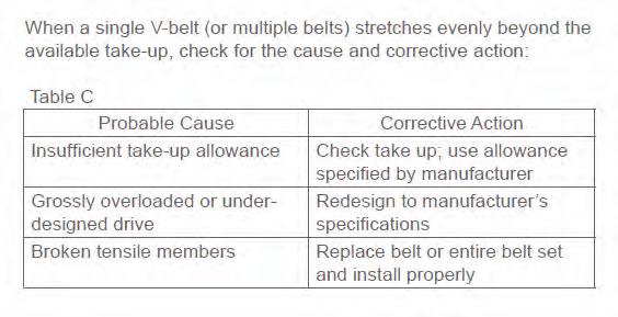
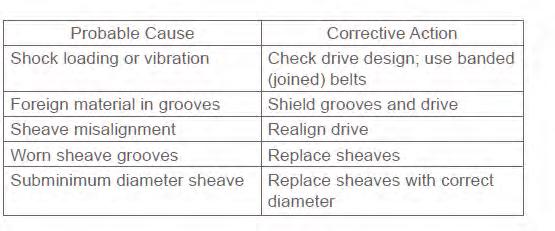
94 Problems Common to Single and Multiple V-Belts Two problems common to both single V-belts and multiple V-belts include belts turning over or coming off the sheave and belts stretching beyond the available take-up. There are a number of probable causes and corrective actions for single or multiple V-belts turning over or coming off the sheave:
95
96 Sheave and Other Drive Component Problems Broken or damaged sheaves, severe sheave groove wear, bent or broken shafts, and extremely hot bearings are also problems that impact V-belt life.
97
98
99


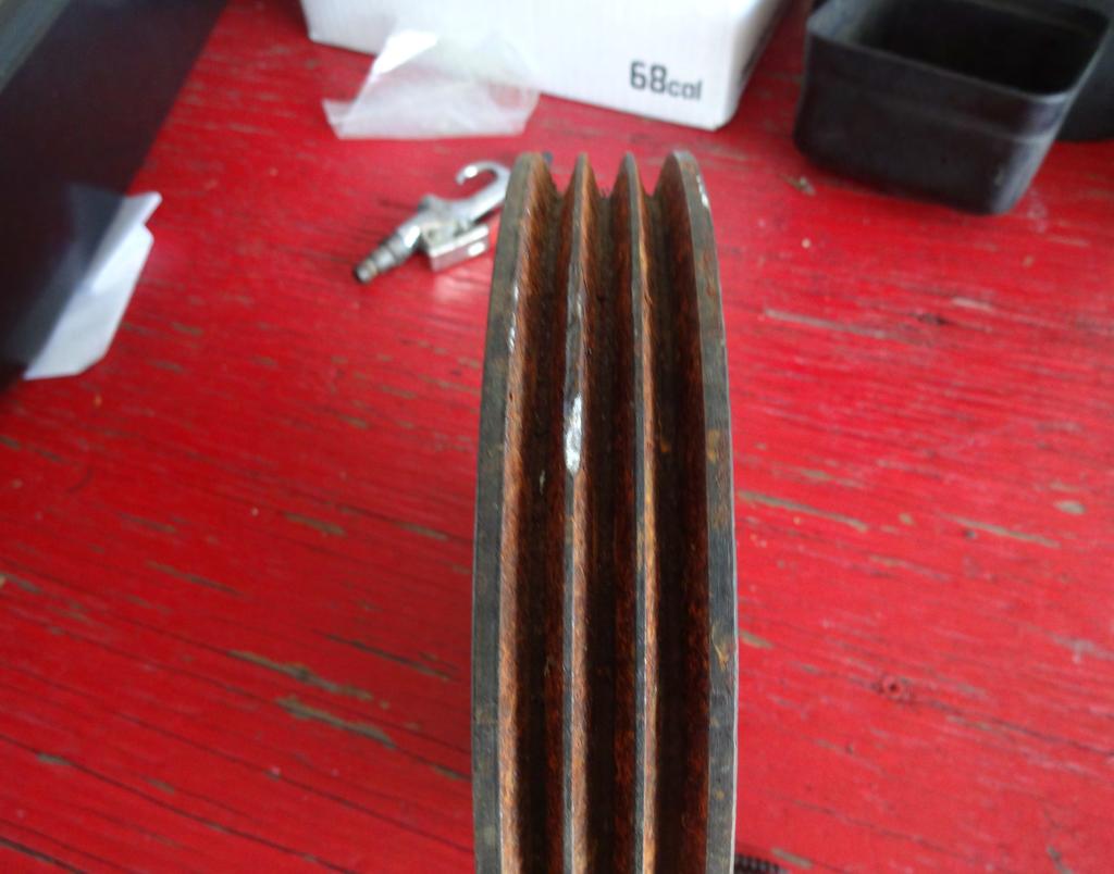
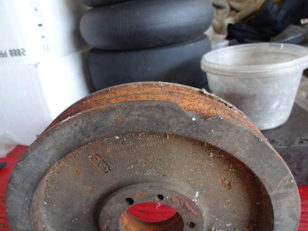
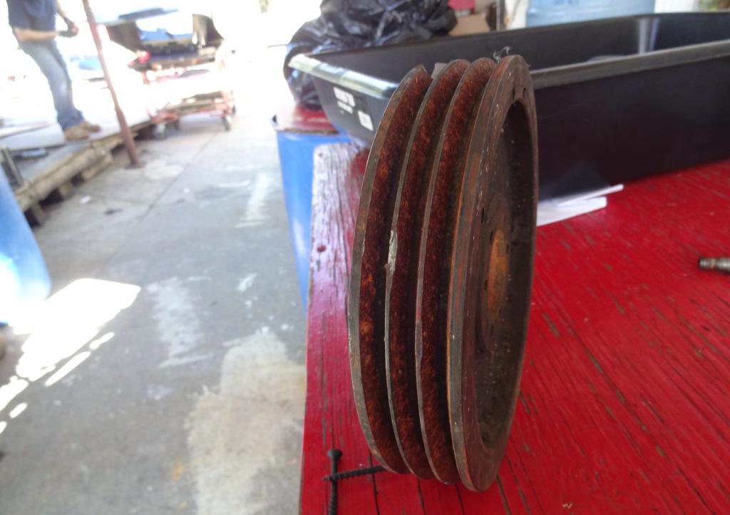
100 It seems improbable that a rubber V-belt could wear out a metal sheave, but it s a fact Many users replace V-belts several times without bothering to check the sheaves for wear. Signs of sheave wear include groove sidewall cupping and/or a polished groove sidewall with ridges. Use a sheave gauge to detect excessive sheave groove wear, and replace sheaves immediately when worn.
101 A broken or damaged sheave also decreases belt life. Sheave damage could result from incorrect installation, such as over tightening the bushing bolts. Or the belt may have been pried onto the sheave, causing the damage. Another probable cause of sheave damage is debris falling into the drive. Install a drive guard to correct the problem.
102 Bent or broken shafts could be caused by a number of factors, including the following: Extreme belt overtension Overdesigned drive Accidental damage Machine design error Sheave mounted too far away from outboard bearing
103
104
105
106
107
108
109
Synchronous Belt Failure Analysis Guide
 Synchronous Belt Failure Analysis Guide Contents Part 1: Common Causes of Belt Failure Normal Belt Wear and Failure Belt Crimp Failures Shock Load Part 2: Improper Belt Installation Tension Introduction
V-Belt Installation, Maintenance & Storage Installation
 V-Belt Installation, Maintenance & Storage Installation 1. Check pulleys for rust, oil, grease, dust, dirt and other foreign materials. Clean the pulleys. Foreign materials accelerate belt wear and dramatically
GatesFacts Technical Information Library Gates Compass Power Transmission CD-ROM version 1.2 The Gates Rubber Company Denver, Colorado USA
 Gary L. Miller Plant Engineering November 7, 1991 DIFFERENCES IN SYNCHRONOUS BELTS All toothed belts are not the same; subtle differences in tooth profiles and construction affect performance. Synchronous
GatesFacts Technical Information Library Gates Compass Power Transmission CD-ROM version 1.2 The Gates Rubber Company Denver, Colorado USA
 Timing Belt Selection And Troubleshooting David E. Roos Maintenance Technology September 1989 Evenly spaced teeth on the bottom surface of synchronous or timing belts mesh with grooves on the pulleys for
ENDURA HI-TECH V BELTS
 ENDURA HI-TECH V BELTS USER S MANUAL QUALITY DURABILITY - PERFORMANCE Contents SECTIONs Particulars Page No SECTION 1 V Belts Construction 1 V Belts Drive Advantages 1 SECTION 2 - Preventive Maintenance
FOR MICRO-V XF MULTI-RIBBED BELTS
 E2/70407 TROUBLESHOOTING GUIDE FOR MICRO-V XF MULTI-RIBBED BELTS In older cars, the accessory belt drive system or fan belt system used V-belts. In 1982, Gates introduced the Micro-V multi-ribbed belt,
REMY TECHNICAL SERVICE BULLETIN
 June 2018 REMY TECHNICAL SERVICE BULLETIN Remy Power Products is continuously adding technical training and technical information. We welcome suggestions. If there is something technical you would like
Mechanical Equipment - Course 230.1
 Mechanical Equipment - Course 230.1 BELT DRIVES A conunon method of transmitting power is a combination of belts and pulleys, There are many types of belts and pulleys used for the transmission of power
DIAMOND ROLLER CHAIN. For Agricultural and Construction Equipment
 DIAMOND ROLLER CHAIN For Agricultural and Construction Equipment FABRICATION While roller chain would appear to be a simple product, the number of components in a ten foot section of 40 pitch chain totals
Timing Belts. Economical means to transfer power Meshing between belt teeth and those of the sprocket Clean No slip characteristic.
 Timing Belts Timing Belts Economical means to transfer power Meshing between belt teeth and those of the sprocket Clean No slip characteristic. Origins of the Timing Belt Trapezoidal profile developed
LONG LENGTH DESIGN MANUAL CONTENTS PAGE. Introduction Long Length features & benefits... 2 Long Length belting programme... 7
 DESIGN MANUAL LONG CONTENTS PAGE LENGTH Introduction Long Length features & benefits... 2 Long Length belting programme... 7 Drive Design Belt drive selection procedure... 8 Belt pitch selection guides...
Timing Belt Design Hints A guide to Timing Belt drives
 Timing Belt Design Hints A guide to Timing Belt drives Properties This table is provided to assist in specifying an Optibelt drive element for a particular drive application. Ambient temperature Maximum/minimum
Engine Belt System Overview
 Engine Belt System Overview Note: The majority of new vehicles use Micro-V belts to power their front end accessories. However, V-belts (not shown in this engine illustration) are still used on some vehicles.
Timing Belt Installation
 Timing Belt Installation The following is an installation guideline designed to combat problems resulting from improper installation of timing belt drives. 1) Loosen Motor. Check to make sure that the
V-Belt and Timing Belt Installation and Maintenance
 V-Belt and Timing Belt Installation and Maintenance Introduction The purpose of this manual is simple: to help you get maximum value from your belt drives. As you review this information, you ll understand
Belt Drive Preventive Maintenance Manual
 VAC VAC VAC VAC VAC VAC Belt Drive Preventive Maintenance Manual VAC Belt Drive Preventive Maintenance Manual Preventive Maintenance Saves Time & Money Compared to the mechanical problems and costs incurred
Clutch Diagnosis - Causes of Failure
 Clutch Diagnosis - Causes of Failure Guide Tube wear, Spline wear, Mainshaft Bearing wear Worn Flywheel Bearing, ridged or heat damaged Flywheel surface Worn/siezed Release Arm pivots, friction lining
GatesFacts Technical Information Library Gates Compass Power Transmission CD-ROM version 1.2 The Gates Rubber Company Denver, Colorado USA
 SELECTING SYNCHRONOUS BELTS FOR PRECISE POSITIONING A W Wallin Power Transmission Design February, 1989 Synchronous belts are well known for precise positioning. However, some precision applications require
GatesFacts Technical Information Library Gates Compass Power Transmission CD-ROM version 1.2 The Gates Rubber Company Denver, Colorado USA
 Specialized Synchronous Belts David E. Roos Machine Design June 8, 1989 Uncommon belts perform operation that standard belts cannot. And if an unusual design is not readily available, one can be made to
DIAMOND CHAIN COMPANY INC. Maintenance Guide
 Maintenance Guide 2006 BULLETIN 1067 TABLE OF CONTENTS ORDERING INFORMATION 3 INSTALLATION 4 LUBRICATION 5 INSPECTIONS 6 ELONGATION LIMITS 7 WHAT IS CHAIN WEAR? Did you know Chain does not STRETCH? Chain
Randy Recommends... If your bike has chain drive, here are some things you should know.
 Chains part 1: Sizing Motorcycle drive chains are made up of alternating internal links and external links, connected by pins. The internal links consist of two plates connected to each other through two
Tire 16 inch 225/75R inch 255/60R 18
 417009 143 1. SPECIFICATIONS Description Specification Tire 16 inch 225/75R 16 Tire inflation pressure 18 inch 255/60R 18 Front: 32 psi Rear: 32 psi (44 psi: when the vehicle is fully laden with luggage)
GATES POWERGRIP TIMING BELTS MENU
 GATES POWERGRIP TIMING BELTS MENU PowerGrip timing belt installation PowerGrip timing belt troubleshooting guide More about PowerGrip timing belts GATES POWERGRIP TIMING BELTS INSTALLATION Timing Belt
GatesFacts Technical Information Library Gates Compass Power Transmission CD-ROM version 1.2 The Gates Rubber Company Denver, Colorado USA
 HOT AND COLD RUNNING BELTS James Shepherd Power Transmission Design Magazine October 1992 Temperature has a big influence on the life of V-belts, especially in very hot or cold environments. But, there
CONVEYOR BELTING INSTALLATION, OPERATION AND MAINTENANCE MANUAL
 CONVEYOR BELTING INSTALLATION, OPERATION AND MAINTENANCE MANUAL Index 1. Safety Precautions... 3 2. Introduction/ Applicable equipment... 4 2. Handling & Storage... 5 3. Installation/ Set Up... 6 4. Operation
WARNING DO NOT USE THE PRODUCTS IN THIS GUIDE IN AIRCRAFT APPLICATIONS. THE PRODUCTS IN THIS GUIDE ARE NOT INTENDED FOR USE IN AIRCRAFT APPLICATIONS.
 P O W E R T R A N S M I S S I O N P R O D U C T S power transmission belt drive system Installation, Maintenance and Troubleshooting Guide WARNING DO NOT USE THE PRODUCTS IN THIS GUIDE IN AIRCRAFT APPLICATIONS.
Gear Drives. A third gear added to the system will rotate in the same direction as the drive gear Equal diameters = Equal number of teeth = Same speed
 Gear Drive Systems Gear Drives Gear Drive: Synchronous mechanical drive that uses gears to transfer power Gear: A toothed wheel that meshes with other toothed wheels to transfer rotational power Pinion
DIAGNOSIS AND TESTING
 303-05-1 Accessory Drive 303-05-1 DIAGNOSIS AND TESTING Accessory Drive Inspection and Verification CAUTION: Under no circumstances should the accessory drive belt, tensioner or pulleys be lubricated as
Automotive Belts, Tensioners, Pulleys 101. Introduction to Front-End Accessory Drive Systems
 Automotive Belts, Tensioners, Pulleys 101 Introduction to Front-End Accessory Drive Systems Introduction to Front-End Accessory Drive and V-Belt Drive Systems Table of Contents Engine Belt System Overview...Page
2.- HANDLING OF VALVES BEFORE ASSEMBLY 3.- FITTING THE VALVE TO THE REST OF THE ASSEMBLY 5.- PERIODICAL INSPECTION OF THE VALVE AND MAINTENANCE
 Page 1 of 16 CONTENTS 1.- INTRODUCTION 2.- HANDLING OF VALVES BEFORE ASSEMBLY 3.- FITTING THE VALVE TO THE REST OF THE ASSEMBLY 4.- OPERATION OF A BALL VALVE 5.- PERIODICAL INSPECTION OF THE VALVE AND
Tire 16 inch 225/75R inch 255/60R 18
 417009 133 1. SPECIFICATIONS Description Specification Tire 16 inch 225/75R 16 Tire inflation pressure 18 inch 255/60R 18 Front: 32 psi Rear: 32 psi (44 psi: when the vehicle is fully laden with luggage)
Power Transmission Belt Drive System Installation, Maintenance and Troubleshooting Guide
 Power Transmission Drive System Installation, Maintenance and Troubleshooting Guide www.contitech.us Table of Contents Installation Guide 2 Table of Contents Installation V-s V-s 3 Banded s Torque Team
Auger Belt Tension Adjustment DB7659
 Rev 1.0 3-23-13 Auger Belt Tension Adjustment DB7659 WARNING Entanglement Hazard - Before performing any adjustment procedures, make sure the engine is off and remove the spark plug wire from the spark
Industrial Belt and drive preventive maintenance E2/20087
 E2/20087 Industrial Belt and drive preventive maintenance HIGH PERFORMANCE AND COMPREHENSIVE PRODUCT RANGE Throughout the years, the Gates Corporation has played a key role in the creation and development
Timing Belt Replacement
 Timing Belt Replacement Tools Required Timing Belt Alignment Kit Crank Hub TORX Socket Removal Procedure 1. Disconnect the negative battery cable. 2. Remove the timing belt front cover. 3. Rotate the crankshaft
GatesFacts Technical Information Library Gates Compass Power Transmission CD-ROM version 1.2 The Gates Rubber Company Denver, Colorado USA
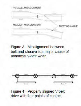
 PREVENTING DRIVE BELT ALIGNMENT PROBLEMS Dan Parsons Plant Engineering July, 1993 Amount of angular and parallel misalignment determines what action to take. Misalignment is one of the most common causes
Engine Bearing Failure Analysis By Clevite 1965
 Engine Bearing Failure Analysis By Clevite 1965 RECOMMENDED BEARING INSTALLATION TOLERANCES CRANKCASE TOLERANCES Finish of main bores 80 micro inch or better. Bore Tolerance.001 " up to 10" bore,.002"
PO Box 645, Stockton, Missouri, FAX superiorgearbox.com
 I000-7000-D0447-A 4/7/05 1 SAFETY PRECAUTIONS CAUTION Please read this entire document prior to operating the gear drive. Gear drive failure and / or injury to operators may be caused by improper installation,
GatesFacts Technical Information Library Gates Compass Power Transmission CD-ROM version 1.2 The Gates Rubber Company Denver, Colorado USA
 SIZING UP V-RIBBED BELTS Gary Porter Machine Design October 22, 1992 V-ribbed belts offer several advantages to power transmission drive design. Classical V-belts have a profile shaped like a modified
Marine Engineering Exam Resource Review of Couplings
 1. What are rigid couplings used for? Used to join drive shafts together. True alignment and rigidity are required. Example Drive shafts and production lines, bridge cranes, solid shaft that needs to be
OPERATIONS MANUAL LEVER CHAIN HOIST
 OPERATIONS MANUAL LEVER CHAIN HOIST IMPORTANT SAFETY INFORMATION Please read, understand and follow all safety information contained in these instructions prior to the use of this hoist. Retain these instructions
TIMING AND ACCESSORY Ranges. Diagnostic Expert Analysis & Recommendations
 Diagnostic Expert Analysis & Recommendations MAJOR CAUSES OF TIMING BELT FAILURES: 1 Uneven breakage 2 A clean break 3 Detached or separation of the belt teeth 4 Ripped teeth 5 Split teeth 6 Loss of teeth
Troubleshooting Power Transmission Couplings
 Troubleshooting Power Transmission Couplings Introduction Power transmission couplings are used to connect two shafts that turn in the same direction on the same centerline. There are three principle types
MAINTENANCE TECHNIQUES and GEAR UNIT FAILURE MODES. MIKE FIELD DAVID BROWN GEAR INDUSTRIES Revision 1
 MAINTENANCE TECHNIQUES and GEAR UNIT FAILURE MODES MIKE FIELD DAVID BROWN GEAR INDUSTRIES Revision 1 Maintenance Regular maintenance saves money One hour per week of effort can save millions in lost production
Index for each Part of Tires
 Index for each Part of Tires 1. Tread NORMAL TREAD WEAR...57 UNEVEN TREAD WEAR (SHOULDER)... 58 UNEVEN TREAD WEAR (CENTER)... 59 IRREGULAR WEAR: ABRASION... 60 SPOT WEAR...61 TREAD RUBBER REVERSION...62
INJECTION MOULDING TROUBLESHOOTING GUIDE
 Page : 1 / 12 BLACK SPECKS OR STREAKS Excessive residence time in the barrel Hang-up of Molten material in the injection barrel or runner system Contamination of the injection barrel Degradation due to
SECTION Accessory Drive
 303-05-i Accessory Drive 303-05-i SECTION 303-05 Accessory Drive CONTENTS PAGE DIAGNOSIS AND TESTING Accessory Drive... 303-05-2 Inspection and Verification... 303-05-2 Symptom Chart... 303-05-5 Component
Failures of Rolling Bearings in Bar and Rod Mill
 Case Study Failures of Rolling Bearings in Bar and Rod Mill by Christo Iliev University of Zimbabwe, Dept. of Mechanical Engineering Harare, Zimbabwe INTRODUCTION Bar and rod mills can usually be found
PO Box 645, Stockton, Missouri, FAX superiorgearbox.com W D0446-A 4/1/05 1
 W000-7000-D0446-A 4/1/05 1 SAFETY PRECAUTIONS CAUTION Please read this entire document prior to operating the gear drive. Gear drive failure and / or injury to operators may be caused by improper installation,
GatesFacts Technical Information Library Gates Compass Power Transmission CD-ROM version 1.2 The Gates Rubber Company Denver, Colorado USA
 MAKING THE RIGHT SHAFT CONNECTIONS Daniel Schwartz & Gary Porter Power Transmission Design August, 1996 Securing a belt pulley to a drive shaft often seems like such a routine task, that engineers and
DIAGNOSIS AND TESTING
 205-02B-1 DIAGNOSIS AND TESTING Rear Drive Axle and Differential Special Tool(s) Dial Indicator Gauge with Holding Fixture 100-002 (TOOL-4201-C) or equivalent 205-02B-1 4 Has the driveline system been
750 Series Press Conveyor Installation and Maintenance Manual
 750 Series Press Conveyor Installation and Maintenance Manual Metzgar Conveyor Co. - 2010 METZGAR CONVEYORS SAFETY PRECAUTIONS WARNING: DO NOT ATTEMPT MAINTENANCE ON ANY CONVEYORS WHILE IN OPERATION. BEFORE
Maintenance and Repair
 Maintenance and Repair WARNING ALWAYS shut off the engine, remove key from ignition, make sure the engine is cool, and disconnect the spark plug and positive battery terminal from the battery before cleaning,
SECTION Wheels and Tires
 204-04-i Wheels and Tires 204-04-i SECTION 204-04 Wheels and Tires CONTENTS PAGE DIAGNOSIS AND TESTING Wheels And Tires... 204-04-2 Inspection and Verification... 204-04-2 Tire Wear... 204-04-3 Symptom
COYOTE ENTERPRISES, INC. 9/10 BLAST WHEEL MAINTENANCE & ASSEMBLY MANUAL
 COYOTE ENTERPRISES, INC. 9/10 BLAST WHEEL MAINTENANCE & ASSEMBLY MANUAL Parts & Machinery for the Abrasive Blast Industry 27301 East 121st Street Coweta, Oklahoma 74429 (918) 486-8411 Fax (918) 486-8412
Introduction. Lubrication Related Failures. Gear Couplings. Failure Analysis All Types (Page 1 of 7)
") All Types (Page 1 of 7) Introduction A gear coupling serves as a mechanical device which connects shafts of two separate machines and accommodates small amounts of shaft misalignment. Commercial gear couplings
All Types (Page 1 of 7) Introduction A gear coupling serves as a mechanical device which connects shafts of two separate machines and accommodates small amounts of shaft misalignment. Commercial gear couplings
7-6 COOLING KJ COOLING (Continued) COOLING SYSTEM DIAGNOSIS CHART - GAS ENGINE COOLING SYSTEM DIAGNOSIS CHART CONDITION POSSIBLE CAUSES CORRECTION TEM
 COOLING SYSTEM DIAGNOSIS CHART - GAS ENGINE COOLING SYSTEM DIAGNOSIS CHART CONDITION POSSIBLE CAUSES CORRECTION TEM") 7-6 COOLING KJ COOLING (Continued) COOLING SYSTEM DIAGNOSIS CHART - GAS ENGINE COOLING SYSTEM DIAGNOSIS CHART CONDITION POSSIBLE CAUSES CORRECTION TEMPERATURE GAUGE READS LOW 1. Has a Diagnostic Trouble
7-6 COOLING KJ COOLING (Continued) COOLING SYSTEM DIAGNOSIS CHART - GAS ENGINE COOLING SYSTEM DIAGNOSIS CHART CONDITION POSSIBLE CAUSES CORRECTION TEMPERATURE GAUGE READS LOW 1. Has a Diagnostic Trouble
Automatic Belt Tensioners:
 Automatic Belt Tensioners: Why cars have them and where to get them Over 100 million vehicles use automatic belt tensioners. Tensioners, like any other part, don t last forever, and automotive technicians
Poly-V-Belts February Description and Operation of the Poly-V- Belts. Removal of the Poly-V- Belts. Inspection of the Poly-V- Belts
 1 02 13-18 SUBJECT DATE Poly-V-Belts February 2018 Additions, Revisions, or Updates Publication Number / Title Platform Section Title Change Description and Operation of the Poly-V- Belts DDC-SVC-MAN-0190
2011 Focus Workshop Manual. DESCRIPTION AND OPERATION Procedure revision date: 06/24/2010
 SECTION 303-05: Accessory Drive 2011 Focus Workshop Manual DESCRIPTION AND OPERATION Procedure revision date: 06/24/2010 Accessory Drive The accessory drive: has a single serpentine drive belt with 6 ribs.
2002 F-Super Duty /Excursion Workshop Manual
 Page 1 of 5 SECTION 205-02D: Rear Drive Axle/Differential Ford 10.50-Inch Ring Gear 2002 F-Super Duty 250-550/Excursion Workshop Manual DIAGNOSIS AND TESTING Procedure revision date: 02/02/2005 Rear Drive
Fitting-removal and maintenance
 Fitting-removal and maintenance Fitting of bearings 136 General rules 136 Fitting principles 136 Hot fitting 137 Press fitting (or with anti-rebound hammer) 138 Adapter sleeves 139 Removal of bearings
Jason Industrial Inc.
 Jason Industrial Inc. POWER TRANSMISSION V-BELTS Select Multi-Plus A & B Belts and Discontinue Your 4L & 5L Inventory! Dual Part Number System is more than just labeling. FHP & Classical have the same
POWEr TrANSMISSION INSTALLATION & MAINTENANCE
 POWEr TrANSMISSION INSTALLATION & MAINTENANCE 2 rue Claude MONNET 70000 VESOUL Installation and Maintenance Instructions Safety: Before the beginning of any maintenance work, make sure that all machine
NECO Pumping Systems
 INSTALLATION OPERATION & MAINTENANCE INSTRUCTIONS For Your NECO Pumping Systems Fuel Oil Transfer System THIS COMPLETELY ASSEMBLED, TESTED, PACKAGED SYSTEM IS OF THE HIGHEST QUALITY AND DESIGN. TO OBTAIN
BELT DRIVE PREVENTIVE MAINTENANCE & SAFETY MANUAL
 BELT DRIVE PREVENTIVE MAINTENANCE & SAFETY MANUAL The Driving Force in Power Transmission TABLE OF CONTENTS Foreword Why Have a Preventive Maintenance Program?... 1 Maintaining a Safe Working Environment...
Service Bulletin No. 2916
 MODEL TYPE SECTION/GROUP DATE All MCI Coaches Service Information 12--Suspension Oct. 13, 2005 SUBJECT TORQUE ROD BUSHING INSPECTION CONDITIONS Description: This service information bulletin provides bushing
AMY SAYS: Drop Forged Pear Link. Eyes are tapered and an eye buffer is sewn in the eye for better fit and wear. Anatomy of an
 AMY SAYS: Drop Forged Pear Link Eyes are tapered and an eye buffer is sewn in the eye for better fit and wear. AMY Anatomy of an V Sling Full two-ply web bodies which allow for only one splice. (no edge
Winch Trouble Shooting Guide
 Winch Trouble Shooting Guide This guide has been compiled to help resolve common problems often experienced with winches. It is only a guide to help diagnose and correct some of the more common faults
Tyre Care & Safety for Agricultural Tires
 Tyre Care & Safety for Agricultural Tires Operating Instructions Some Points Worth Remembering; The BKT Agricultural tires are designed for Agricultural tractors, Trailers & Implements. Before using them
Provided by: Operating, Maintenance & Parts Manual
 Provided by: www.hoistsdirect.com TB681.qxd 11/29/2004 3:04 PM Page 1 Operating, Maintenance & Parts Manual TB603 Manually Lever Operated Chain Hoist 1100 POUNDS MAXIMUM CAPACITY (500 kg) Follow all instructions
Convertible - Rated 3 4-Ton /2-Ton Nylon Strap Hoists Refer to any questions about the use, application, repair or testing of this hoist to:
 Operating and Servicing Instructions for Convertible - Rated 3 4-Ton - 1 1 /2-Ton Nylon Strap Hoists Refer to any questions about the use, application, repair or testing of this hoist to: Hubbell / Chance
BELTS BELTS V-BELTS SYNCHRONOUS BELTS IMPORTANT REMINDER
 IMPORTANT REMINDER When using ARAMID FIBER REINFORCED (KEVLAR) be sure NOT to tension at higher force than recommended for standard conventional construction belts. Specially designed sheaves may be required
WARM ENGINE STARTING PROCEDURE
 saw starting COLD ENGINE STARTING PROCEDURE 1. Pull the choke lever out. 2. Lock the throttle in the start position by depressing and holding the throttle lock button (C) while releasing the trigger (A)
Belt Installation, Tracking, and Maintenance Guide
 Belt Installation, Tracking, and Maintenance Guide LEWCO, Inc. 2018 706 Lane St. Sandusky, Ohio 44870 USA Phone: (419) 625-4014 Fax: (419) 625-1247 Revised 00/00/18 conveyorsales@lewcoinc.com www.lewcoinc.com
Mechanical Actuators
 Mechanical Actuators Translating Machine Screw Actuators 100-Ton, 150-Ton & 250-Ton Capacity Installation, Operation & Maintenance Instructions Publication Part No. SK-2389-100 CAUTION This manual contains
Mounting and Service Instructions
 Mounting and Service Instrucs Standard safety rules should be observed Switch off the current before carrying out work at the transmission unit. Make sure that the transmission unit cannot be started while
CAUTION: Do not clean, wash or soak transmission seals in cleaning solvents. Dry all parts with compressed air.
 «1993 Thunderbird/Cougar Table of Contents» «Group 07: TRANSMISSION» «Section 07-03: Transmission, Manual--M5R2» «CLEANING AND INSPECTION» Transmission Cleaning CAUTION: Do not clean, wash or soak transmission
IDENTIFYING DISC COUPLING FAILURES COUPLING FUNDAMENTALS
 IDENTIFYING DISC COUPLING FAILURES While couplings are designed for infinite life, they must be operated within their intended design limits in order to achieve optimal performance. Due to installation
HOW BELT DRIVES IMPACT OVERHUNG LOAD
 HOW BELT DRIVES IMPACT OVERHUNG LOAD HOW TO IMPROVE WORKER SAFETY AND REDUCE MAINTENANCE Introduction Today s belt drive systems are capable of transmitting enormous power in a compact space. What impact
FTM-L SERIES SINGLE OR TWIN DIRECT STEAM MIXER KETTLE COMPLETE WITH HYDRAULIC POWER TILT BRIDGE PARTS AND SERVICE MANUAL
 FTM-L SERIES SINGLE OR TWIN DIRECT STEAM MIXER KETTLE COMPLETE WITH HYDRAULIC POWER TILT BRIDGE PARTS AND SERVICE MANUAL EFFECTIVE SEPTEMBER 19, 2014 Superseding All Previous Parts Lists. The Company reserves
Installation Instructions. QuickSilver Shifter. Fits: GM, Ford, Chrysler Transmissions See Application Guide for Specific Applications Part # 80683
 Installation Instructions QuickSilver Shifter Fits: GM, Ford, Chrysler Transmissions See Application Guide for Specific Applications Part # 80683 WORK SAFELY! For maximum safety, perform this installation
SECTION 6 3 SERVICE PROCEDURES AND SPECIFICATIONS. Chassis
 SERVICE PROCEDURES AND SPECIFICATIONS Chassis SECTION 6 3 Specifications........................................... 208 Checking brake fluid...................................... 210 Checking power steering
BLISS PELLET MILL 200
 BLISS PELLET MILL 200 TORQUE GUIDE 200 PELLET MILL The Brake B-loc 112 series torque 225nm The Brake b-loc 115 series torque 142nm Mainshaft nut Drive belt 250 mm Drive belt 340mm Roll settings Gap for
Part 7 DO IT YOURSELF MAINTENANCE
 Part 7 DO IT YOURSELF MAINTENANCE Chapter 7 2 Engine and Chassis Checking the engine oil level Checking the engine coolant level Checking brake fluid Checking power steering fluid Checking tire pressure
2013 RT / 2014RT / 2015 RT - Shock Spring Adjuster Installation Instructions
 2013 RT / 2014RT / 2015 RT - Shock Spring Adjuster Installation Instructions Billet Aluminum Adjusters (2) Shock Spring Compressors (Optional) Spanner Wrench (1) BajaRon Decals Not Shown (4) Adjuster Scuff
White Paper. Next Generation Carbon Synchronous Belts. Making Roller Chain Obsolete?
 Next Generation Carbon Synchronous Belts. Making Roller Chain Obsolete? Introduction Is a synchronous belt drive system really any match for a roller chain drive in high-torque applications? Thirty years
22-1 GROUP 22 MANUAL TRANSAXLE CONTENTS MANUAL TRANSAXLE... 22A MANUAL TRANSAXLE OVERHAUL... 22B
 22-1 GROUP 22 MANUAL TRANSAXLE CONTENTS............................... 22A OVERHAUL..................... 22B 22A-2 GROUP 22A MANUAL TRANSAXLE CONTENTS GENERAL DESCRIPTION......... 22A-3 DIAGNOSIS 22A-6
Table of Contents WARN INDUSTRIES PAGE A1
 INSTALLATION INSTRUCTIONS AND OPERATORS GUIDE ProVantage Bucket Conversion Kit Part Number: 84133 (50 ), 83133 (54 ) and 85133 (60 ) Application: Front Mount Plow* * Not recommended for use with Center
MAINTENANCE - LPX PORTABLE TREATER
 MAINTENANCE - LPX PORTABLE TREATER Proper maintenance of the Portable LPV Treater is critical for peak performance, reliability and accuracy of this system. The following is a guideline for the type of
Why choose Bosch Timing Belts?
 Why choose Bosch Timing Belts? Bosch is one of the largest suppliers of automotive belts to the Australian and New Zealand market, offering a comprehensive range for Australian, Asian and European vehicle
Conditions requiring belt replacement are excessive wear, severe glazing, frayed cords, etc. Replace any belt exhibiting any of these conditions.
 REMOVAL AND INSTALLATION Accessory Drive Belts Conditions requiring belt replacement are excessive wear, severe glazing, frayed cords, etc. Replace any belt exhibiting any of these conditions. NOTE: Minor
MANUAL TRANSAXLE Return to Main Table of Contents
 MANUAL TRANSAXLE Return to Main Table of Contents GENERAL... 2 MANUAL TRANSAXLE CONTROL... 12 SHIFT LEVER ASSEMBLY... 14 MANUAL TRANSAXLE... 15 MANUAL TRANSAXLE ASSEMBLY... 17 FIFTH SPEED SYNCHRONIZER
PUMPS STEAM TURBINES BUILDING & FIRE WASTEWATER SERVICE PUMP CLINIC 15 MECHANICAL SEAL DESIGN, OPERATION AND MAINTENANCE PROBLEMS
 PUMP CLINIC 15 MECHANICAL SEAL DESIGN, OPERATION AND MAINTENANCE PROBLEMS In my seminars I teach that mechanical seals fail prematurely because: The lapped faces open A seal component becomes damaged In
LIPPERTCOMPONENTS, INC.
 LIPPERTCOMPONENTS, INC. SCHWINTEK INWALL SLIDEOUT SYSTEM OPERATION AND SERVICE MANUAL Contents I. Controls 1-1 System components 1 1-1A versions C1 & C2 2 1-2 Motor wiring harness connections 3 1-3 Extend
SECTION 8 2 DO IT YOURSELF MAINTENANCE. Chassis
 DO IT YOURSELF MAINTENANCE Chassis SECTION 8 2 Checking the coolant level of the traction motor................ 184 Checking the radiator....................................... 185 Checking brake fluid........................................
SECTION 7 2 DO IT YOURSELF MAINTENANCE MR2 U. Engine and Chassis
 SECTION 7 2 DO IT YOURSELF MAINTENANCE Engine and Chassis Checking the engine oil level................................. 168 Checking the engine coolant level............................ 169 Checking brake
Installation Tensioning Procedure
 Contents PARTICULARS Introduction PIX X treme HTD Belts Construction Features Designation Pitch range Length range Pulley Dimensions Length tolerances Width tolerances PIX X treme Classical Belts Construction
1. Remove the crankshaft pulley, engine coolant pump pulley and drive belt. 2. Remove the timing belt cover.
 DISASSEMBLY 1. Remove the crankshaft pulley, engine coolant pump pulley and drive belt. 2. Remove the timing belt cover. 3. Turn the crankshaft clockwise and align the timing marks so as to bring the No.
OPERATION SERVICE PARTS TUGIT2. Manually Operated Short Handle Lever Hoist A3140-XXX
 OPERATION SERVICE PARTS TUGIT2 Manually Operated Short Handle Lever Hoist A3140-XXX Sold & Serviced by Morgan Aero 1450 80 th Street SW Everett WA U.S.A. 425/438.9600 SAFETY PRECAUTIONS WARNING! Improper