7-6 COOLING KJ COOLING (Continued) COOLING SYSTEM DIAGNOSIS CHART - GAS ENGINE COOLING SYSTEM DIAGNOSIS CHART CONDITION POSSIBLE CAUSES CORRECTION TEM
|
|
|
- Mervin Parks
- 5 years ago
- Views:
Transcription
1
2
3
4
5
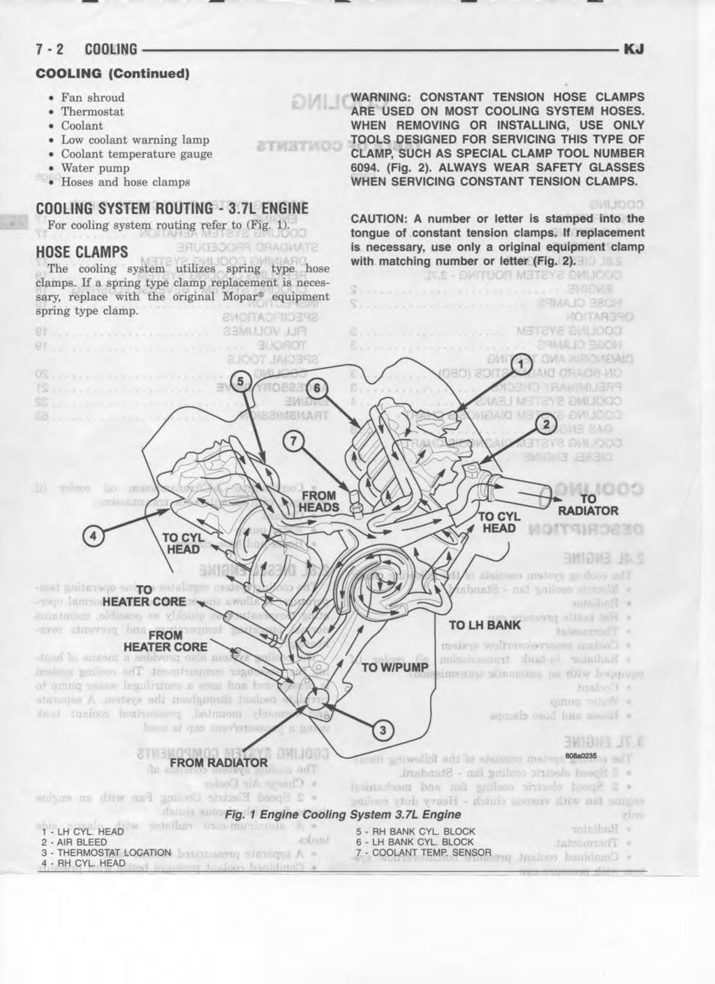
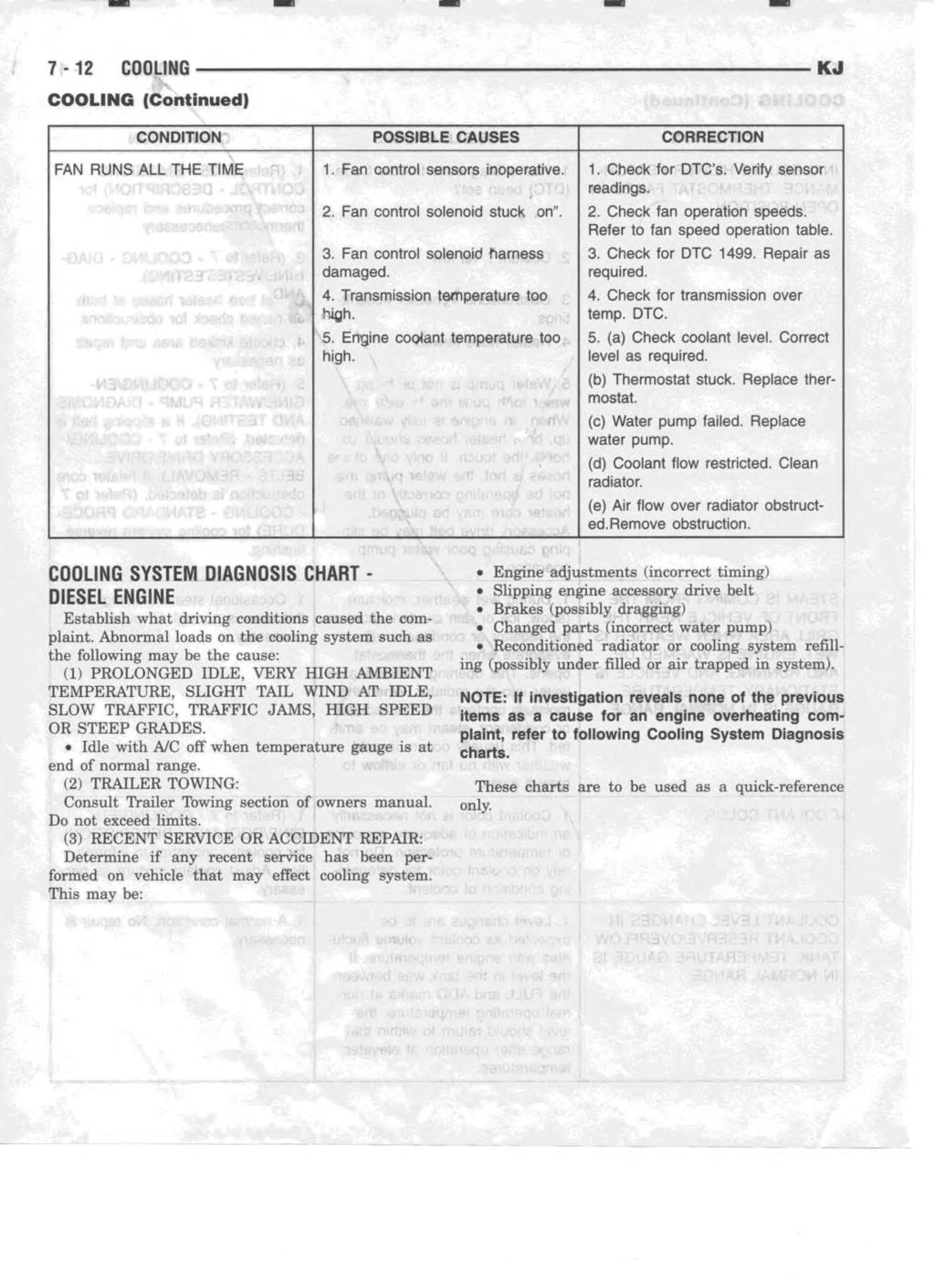
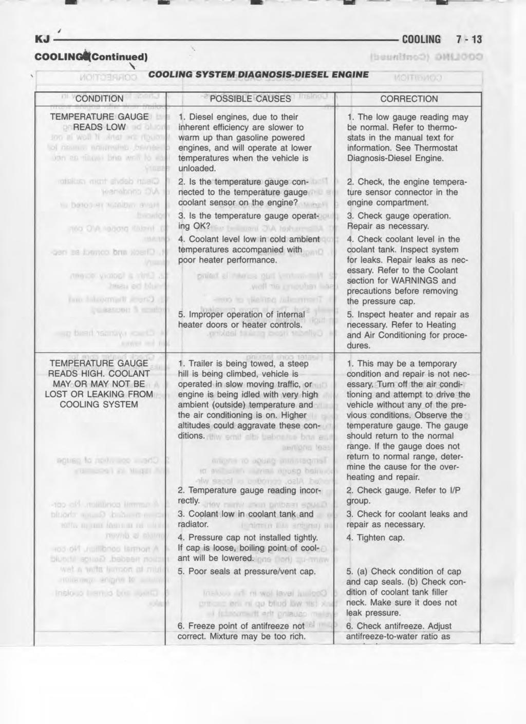
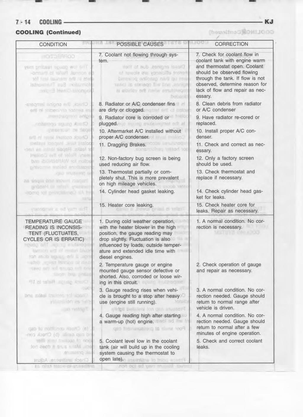
6 7-6 COOLING KJ COOLING (Continued) COOLING SYSTEM DIAGNOSIS CHART - GAS ENGINE COOLING SYSTEM DIAGNOSIS CHART CONDITION POSSIBLE CAUSES CORRECTION TEMPERATURE GAUGE READS LOW 1. Has a Diagnostic Trouble Code (DTC) been set indicating a stuck open thermostat? 2. Is the temperature sending unit connected? 3. Is the temperature gauge operating OK? 4. Coolant level low in cold ambient temperatures accompanied with poor heater performance. 5. Improper operation of internal heater doors or heater controls. 6. Electric fan functioning when not required. 1. Refer to (Refer to 25 - EMIS- SIONS CONTROL - DESCRIP- TION) for On-Board Diagnostics and DTC information. Replace thermostat if necessary. 2. Check the temperature sensor connector. (Refer to 7 - COOLING/ ENGINE/ENGINE COOLANT TEMP SENSOR - DESCRIPTION). Repair connector if necessary. 3. Check gauge operation. Repair as necessary. 4. Check coolant level in the coolant pressure botttle and the radiator. Inspect system for leaks. Repair leaks as necessary. 5. Inspect heater and repair as necessary. (Refer to 24 - HEATING & AIR CONDITIONING - DIAGNO- SIS AND TESTING) 6. Inspect electric fan for proper operation. Refer to Electric Cooling Fan in this section. Refer to group 8W for electric cooling fan and relay circuit schematic data.
7 KJ COOLING 7-7 COOLING (Continued) CONDITION POSSIBLE CAUSES CORRECTION TEMPERATURE GAUGE READS HIGH OR THE COOLANT WARN- ING LAMP ILLUMINATES. COOL- ANT MAY OR MAY NOT BE LOST OR LEAKING FROM THE COOL- ING SYSTEM. 1. Trailer is being towed, a steep hill is being climbed, vehicle is operated in slow moving traffic, or engine is being idled with very high ambient (outside) temperatures and the air conditioning is on. Higher altitudes could aggravate these conditions. 1. This may be a temporary condition and repair is not necessary. Turn off the air conditioning and attempt to drive the vehicle without any of the previous conditions. Observe the temperature gauge. The gauge should return to the normal range. If the gauge does not return to the normal range, determine the cause for overheating and repair. 2. Is the temperature gauge reading correctly? 3. Is the temperature warning illuminating unnecessarily? 4. Coolant low in coolant pressure bottle and radiator? 5. Pressure cap not installed tightly. If cap is loose, boiling point of coolant will be lowered. Also refer to the following Step Check gauge. (Refer to Group 8J - INSTRUMENT CLUSTER). Repair as necessary. 3. Check warning lamp operation. (Refer to Group 8J - INSTRU- MENT CLUSTER).Repair as necessary. 4. Check for coolant leaks and repair as necessary. (Refer to 7 - COOLING - DIAGNOSIS AND TESTING). 5. Tighten cap 6. Poor seals at the radiator cap. 6. (a) Check condition of cap and cap seals. (Refer to 7 - COOLING/ ENGINE/RADIATOR PRESSURE CAP - DIAGNOSIS AND TEST- ING). (b) Check condition of radiator filler neck. If neck is bent or damaged, replace radiator. 7. Coolant not flowing through system. 7. (a) Check condition of pressure bottle cap and cap seals. (Refer to 7 - COOLING/ENGINE/RADIATOR PRESSURE CAP - DIAGNOSIS AND TESTING). (b) Check condition of radiator vent nipple. If neck is damaged, replace radiator. (c) Check condition of the hose from the radiator to the coolant tank. It should fit tight at both ends without any kinks or tears. Replace hose if necessary. (d) Check pressure bottle/overflow tank and tanks hoses for blockage. Repair as necessary.
8 7-8 COOLING KJ COOLING (Continued) CONDITION POSSIBLE CAUSES CORRECTION 8. Incorrect coolant concentration 8. Check coolant. (Refer to 7 - COOLING/ENGINE/COOLANT - DESCRIPTION) for correct coolant/ water mixture ratio. 9. Fan installed backwards on viscous 9. Mount fan on drive correctly. drive. 10. Radiator or A/C condenser fins are dirty or clogged. 11. Radiator core is corroded or plugged. 12. Fuel or ignition system problems. 10. Remove insects and debris. (Refer to 7 - COOLING/ENGINE/ RADIATOR - CLEANING). 11. Have radiator re-cored or replaced. 12. Refer to FUEL and /or IGNI- TION CONTROL for diagnosis. 13. Dragging brakes. 13. Check and correct as necessary. (Refer to 5 - BRAKES - DIAGNOSIS AND TESTING) for correct procedures. 14. Bug screen or cardboard is being used, reducing airflow. 15. Thermostat partially or completely shut. 16. Viscous fan drive not operating properly. 14. Remove bug screen or cardboard. 15. Check thermostat operation and replaces necessary. (Refer to 7 - COOLING/ENGINE/ENGINE COOLANT THERMOSTAT - DIAG- NOSIS AND TESTING). 16. Check fan drive operation and replace as necessary. (Refer to 7 - COOLING/ENGINE/FAN DRIVE VISCOUS CLUTCH - DIAGNOSIS AND TESTING). 17. Cylinder head gasket leaking. 17. Check for cylinder head gasket leaks. (Refer to 7 - COOLING - DIAGNOSIS AND TESTING). For repair, (Refer to 9 - ENGINE/CYL- INDER HEAD - REMOVAL). 18. Heater core leaking. 18. Check heater core for leaks. (Refer to 24 - HEATING & AIR CONDITIONING/PLUMBING/ HEATER CORE - REMOVAL). Repair as necessary. 19. Electric fan not functioning. 19. Inspect electric fan for proper operation. Refer to Electric Cooling Fan in this section. Refer to Group 8W for electric cooling fan and relay circuit schematic data.
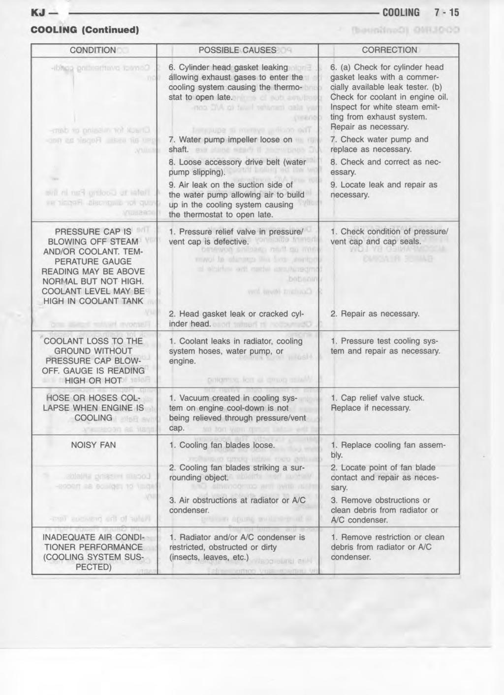
9 KJ COOLING 7-9 COOLING (Continued) CONDITION POSSIBLE CAUSES CORRECTION TEMPERATURE GAUGE READ- ING IS INCONSISTENT (FLUCTU- ATES, CYCLES OR IS ERRATIC) PRESSURE CAP IS BLOWING OFF STEAM AND/OR COOLANT TO COOLANT TANK. TEMPERA- TURE GAUGE READING MAY BE ABOVE NORMAL BUT NOT HIGH. COOLANT LEVEL MAY BE HIGH IN COOLANT RESERVE/OVER- FLOW TANK 1. During cold weather operation, with the heater blower in the high position, the gauge reading may drop slightly. 2. Temperature gauge or engine mounted gauge sensor defective or shorted. Also, corroded or loose wiring in this circuit. 3. Gauge reading rises when vehicle is brought to a stop after heavy use (engine still running) 4. Gauge reading high after restarting a warmed up (hot) engine. 5. Coolant level low in cooling system (air will build up in the cooling system causing the thermostat to open late). 6. Cylinder head gasket leaking allowing exhaust gas to enter cooling system causing a thermostat to open late. 7. Water pump impeller loose on shaft. 8. Loose accessory drive belt. (water pump slipping) 9. Air leak on the suction side of the water pump allows air to build up in cooling system causing thermostat to open late. 1. Pressure relief valve in pressure bottle cap is defective. 1. A normal condition. No correction is necessary. 2. Check operation of gauge and repair if necessary. Refer to Group 8J, Instrument cluster. 3. A normal condition. No correction is necessary. Gauge should return to normal range after vehicle is driven. 4. A normal condition. No correction is necessary. The gauge should return to normal range after a few minutes of engine operation. 5. Check and correct coolant leaks. (Refer to 7 - COOLING - DIAGNO- SIS AND TESTING). 6. (a) Check for cylinder head gasket leaks. (Refer to 7 - COOLING - DIAGNOSIS AND TESTING). (b) Check for coolant in the engine oil. Inspect for white steam emitting from the exhaust system. Repair as necessary. 7. Check water pump and replace as necessary. (Refer to 7 - COOL- ING/ENGINE/WATER PUMP - DIAGNOSIS AND TESTING). 8. (Refer to 7 - COOLING/ACCES- SORY DRIVE/DRIVE BELTS - DIAGNOSIS AND TESTING). Check and correct as necessary. 9. Locate leak and repair as necessary. 1. Check condition of radiator cap and cap seals. (Refer to 7 - COOLING/ENGINE/RADIATOR PRESSURE CAP - DIAGNOSIS AND TESTING). Replace cap as necessary.
10 7-10 COOLING KJ COOLING (Continued) CONDITION POSSIBLE CAUSES CORRECTION COOLANT LOSS TO THE GROUND WITHOUT PRESSURE CAP BLOWOFF. GAUGE READ- ING HIGH OR HOT 1. Coolant leaks in radiator, cooling system hoses, water pump or engine. 1. Pressure test and repair as necessary. (Refer to 7 - COOLING - DIAGNOSIS AND TESTING). DETONATION OR PRE-IGNITION (NOT CAUSED BY IGNITION SYS- TEM). GAUGE MAY OR MAY NOT BE READING HIGH 1. Engine overheating. 1. Check reason for overheating and repair as necessary. 2. Freeze point of coolant not correct. Mixture is too rich or too lean. 2. Check coolant concentration. (Refer to 7 - COOLING/ENGINE/ COOLANT - DESCRIPTION) and adjust ratio as required. HOSE OR HOSES COLLAPSE WHILE ENGINE IS RUNNING 1. Vacuum created in cooling system on engine cool-down is not being relieved through coolant reserve/overflow system. 1. (a) Radiator cap relief valve stuck. (Refer to 7 - COOLING/EN- GINE/RADIATOR PRESSURE CAP - DIAGNOSIS AND TESTING). Replace if necessary (b) Hose between coolant reserve/ overflow tank and radiator is kinked. Repair as necessary. (c) Vent at coolant reserve/overflow tank is plugged. Clean vent and repair as necessary. (d) Reserve/overflow tank is internally blocked or plugged. Check for blockage and repair as necessary. NOISY VISCOUS FAN/DRIVE 1. Fan blades loose. 1. Replace fan blade assembly. (Refer to 7 - COOLING/ENGINE/ RADIATOR FAN - REMOVAL) 2. Fan blades striking a surrounding object. 3. Air obstructions at radiator or air conditioning condenser. 4. Thermal viscous fan drive has defective bearing. 2. Locate point of fan blade contact and repair as necessary. 3. Remove obstructions and/or clean debris or insects from radiator or A/C condenser. 4. Replace fan drive. Bearing is not serviceable. (Refer to 7 - COOL- ING/ENGINE/RADIATOR FAN - REMOVAL).
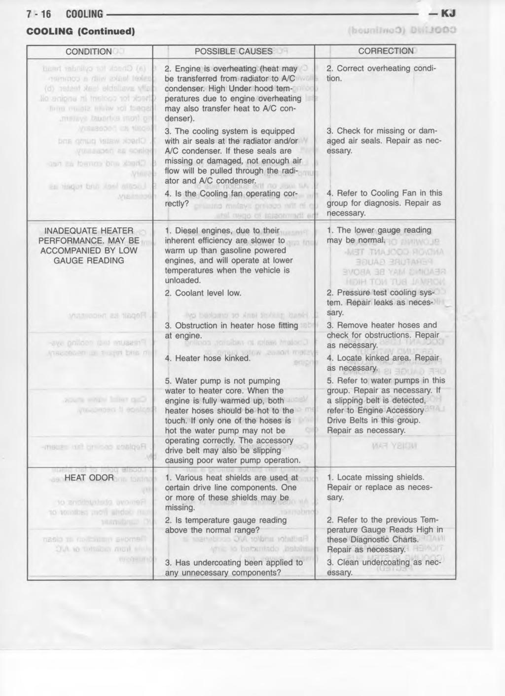
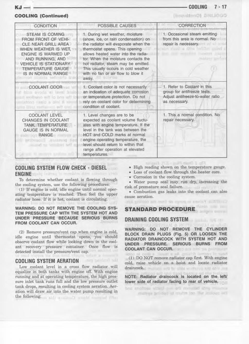
11 KJ COOLING 7-11 COOLING (Continued) CONDITION POSSIBLE CAUSES CORRECTION INADEQUATE HEATER PERFOR- MANCE. THERMOSTAT FAILED IN OPEN POSITION 1. Has a Diagnostic trouble Code (DTC) been set? 1. (Refer to 25 - EMISSIONS CONTROL - DESCRIPTION) for correct procedures and replace thermostat if necessary 2. Coolant level low 2. (Refer to 7 - COOLING - DIAG- NOSIS AND TESTING). 3. Obstructions in heater hose/fittings 3. Remove heater hoses at both ends and check for obstructions 4. Heater hose kinked 4. Locate kinked area and repair as necessary 5. Water pump is not pumping water to/through the heater core. When the engine is fully warmed up, both heater hoses should be hot to the touch. If only one of the hoses is hot, the water pump may not be operating correctly or the heater core may be plugged. Accessory drive belt may be slipping causing poor water pump operation. 5. (Refer to 7 - COOLING/EN- GINE/WATER PUMP - DIAGNOSIS AND TESTING). If a slipping belt is detected, (Refer to 7 - COOLING/ ACCESSORY DRIVE/DRIVE BELTS - REMOVAL). If heater core obstruction is detected, (Refer to 7 - COOLING - STANDARD PROCE- DURE) for cooling system reverse flushing. STEAM IS COMING FROM THE FRONT OF VEHICLE NEAR THE GRILL AREA WHEN WEATHER IS WET, ENGINE IS WARMED UP AND RUNNING, AND VEHICLE IS STATIONARY. TEMPERATURE GAUGE IS IN NORMAL RANGE COOLANT COLOR COOLANT LEVEL CHANGES IN COOLANT RESERVE/OVERFLOW TANK. TEMPERATURE GAUGE IS IN NORMAL RANGE 1. During wet weather, moisture (snow, ice or rain condensation) on the radiator or condensor will evaporate when the thermostat opens. This opening allows heated water into the radiator. When the moisture contacts the hot radiator or condensor, steam may be emitted. This usually occurs in cold weather with no fan or airflow to blow it away. 1. Coolant color is not necessarily an indication of adequate corrosion or temperature protection. Do not rely on coolant color for determining condition of coolant. 1. Level changes are to be expected as coolant volume fluctuates with engine temperature. If the level in the tank was between the FULL and ADD marks at normal operating temperature, the level should return to within that range after operation at elevated temperatures. 1. Occasional steam emitting from this area is normal. No repair is necessary. 1. (Refer to 7 - COOLING/EN- GINE/COOLANT - DESCRIPTION) for coolant concentration information. Adjust coolant mixture as necessary. 1. A normal condition. No repair is necessary.
12
13
14
15
16
17
18
19
20
21
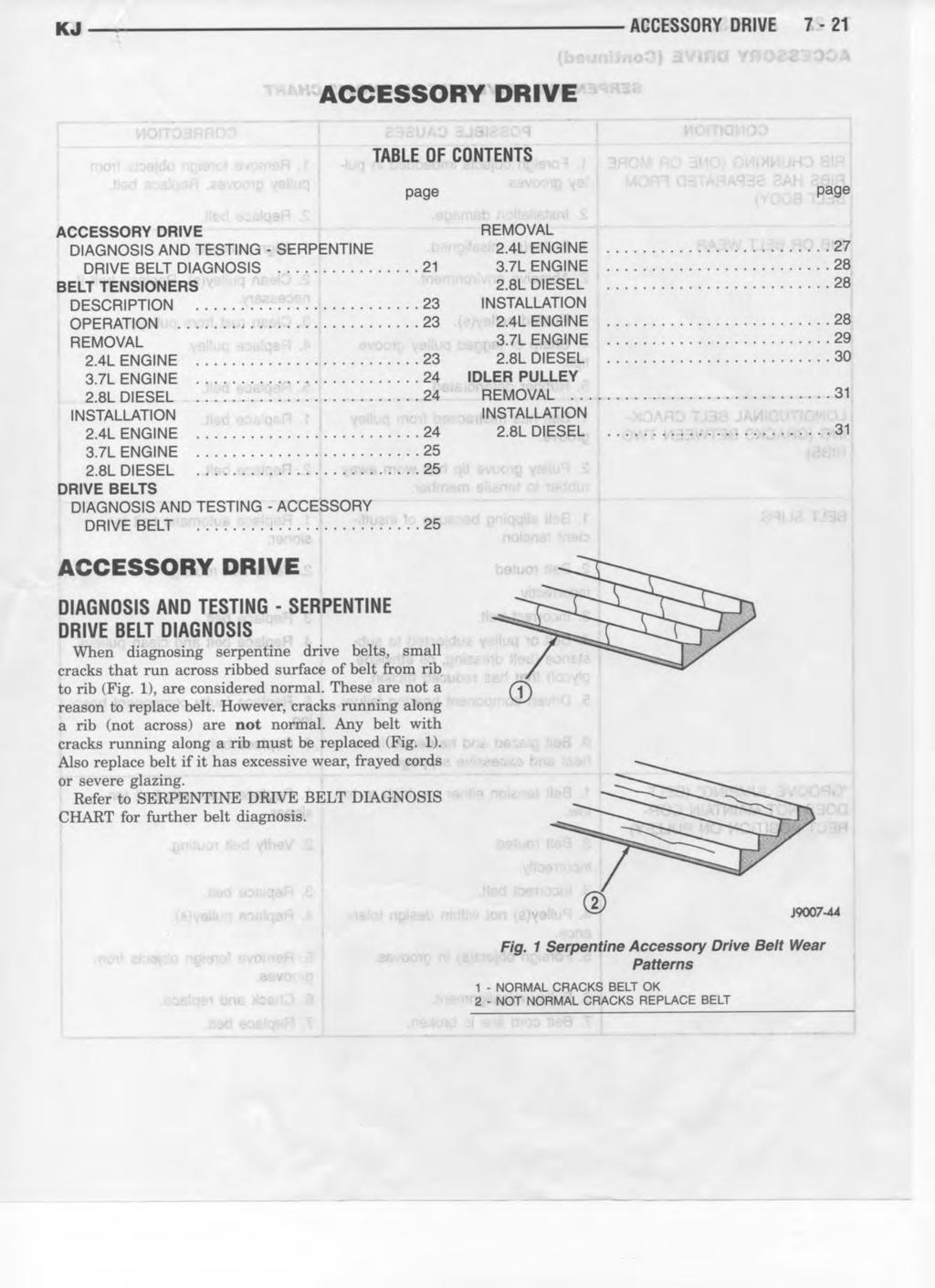
22 KJ ACCESSORY DRIVE 7-17 ACCESSORY DRIVE (Continued) SERPENTINE DRIVE BELT DIAGNOSIS CHART CONDITION POSSIBLE CAUSES CORRECTION RIB CHUNKING (ONE OR MORE RIBS HAS SEPARATED FROM BELT BODY) 1. Foreign objects imbedded in pulley grooves. 1. Remove foreign objects from pulley grooves. Replace belt. 2. Installation damage. 2. Replace belt. RIB OR BELT WEAR 1. Pulley(s) misaligned. 1. Align pulley(s). 2. Abrasive environment. 2. Clean pulley(s). Replace belt if necessary. 3. Rusted pulley(s). 3. Clean rust from pulley(s). 4. Sharp or jagged pulley groove 4. Replace pulley. tips. 5. Rubber deteriorated. 5. Replace belt. LONGITUDINAL BELT CRACK- ING (CRACKS BETWEEN TWO RIBS) BELT SLIPS 1. Belt has mistracked from pulley groove. 2. Pulley groove tip has worn away rubber to tensile member. 1. Belt slipping because of insufficient tension. 1. Replace belt. 2. Replace belt. 1. Replace automatic belt tensioner. 2. Belt routed 2. Verify belt routing. incorrectly 3. Incorrect belt. 3. Replace belt. 4. Belt or pulley subjected to substance (belt dressing, oil ethylene 4. Replace belt and clean pulleys. glycol) that has reduced friction. 5. Driven component bearing failure. 5. Replace faulty component bearing. 6. Belt glazed and hardened from 6. Replace belt. heat and excessive slippage. GROOVE JUMPING (BELT DOES NOT MAINTAIN COR- RECT POSITION ON PULLEY) 1. Belt tension either too high or too low. 1. Replace automatic belt tensioner. 2. Belt routed 2. Verify belt routing. incorrectly. 3. Incorrect belt. 3. Replace belt. 4. Pulley(s) not within design tolerance. 4. Replace pulley(s). 5. Foreign object(s) in grooves. 5. Remove foreign objects from grooves. 6. Pulley misalignment. 6. Check and replace. 7. Belt cord line is broken. 7. Replace belt.
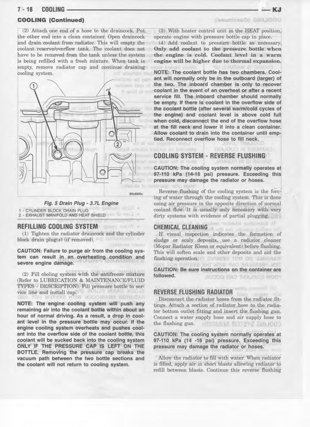
23 7-18 ACCESSORY DRIVE KJ ACCESSORY DRIVE (Continued) CONDITION POSSIBLE CAUSES CORRECTION BELT BROKEN (NOTE: IDEN- TIFY AND CORRECT PROBLEM BEFORE NEW BELT IS INSTALLED) NOISE (OBJECTIONABLE SQUEAL, SQUEAK, OR RUMBLE IS HEARD OR FELT WHILE DRIVE BELT IS IN OPERATION) 1. Excessive tension. 1. Replace belt and automatic belt tensioner. 2. Incorrect belt. 2. Replace belt. 3. Tensile member damaged during 3. Replace belt. belt installation. 4. Severe misalignment. 4. Check and replace. 5. Bracket, pulley, or bearing failure. 5. Replace defective component and belt. 1. Belt slippage. 1. Replace belt or automatic belt tensioner. 2. Bearing noise. 2. Locate and repair. 3. Belt misalignment. 3. Replace belt. 4. Belt-to-pulley mismatch. 4. Install correct belt. BELT TENSIONERS REMOVAL DESCRIPTION The automatic belt tensioner is a spring loaded arm and pulley assembly. The tensioner assembly is designed to apply constant pressure on the accessory drive belt to maintain proper belt tension. OPERATION 2.4L ENGINE (1) Remove accessory drive belt (Refer to 7 - COOLING/ACCESSORY DRIVE/DRIVE BELTS - REMOVAL). (2) Remove tensioner assembly from engine accessory drive bracket (Fig. 2). WARNING: THE AUTOMATIC BELT TENSIONER ASSEMBLY IS SPRING LOADED. DO NOT ATTEMPT TO DISASSEMBLE THE TENSIONER ASSEMBLY. The automatic belt tensioner maintains correct belt tension using a coiled spring within the tensioner housing. The spring applies pressure to the tensioner arm pressing the arm into the belt, tensioning the belt. If a new belt is being installed, the arrow must be within approximately 3 mm (1/8 in.) of indexing mark. Belt is considered new if it has been used 15 minutes or less. If this specification cannot be met, check for: The wrong belt being installed (incorrect length/ width) Worn bearings on an engine accessory (A/C compressor, power steering pump, water pump, idler pulley or generator) A pulley on an engine accessory being loose Misalignment of an engine accessory Belt incorrectly routed. Fig. 2 Accessory Drive Bracket 1- UPPER TIMING BELT COVER 2- LOWER TIMING BELT COVER 3- BELT TENSIONER 4- ACCESSORY DRIVE BRACKET
24
25
26
27
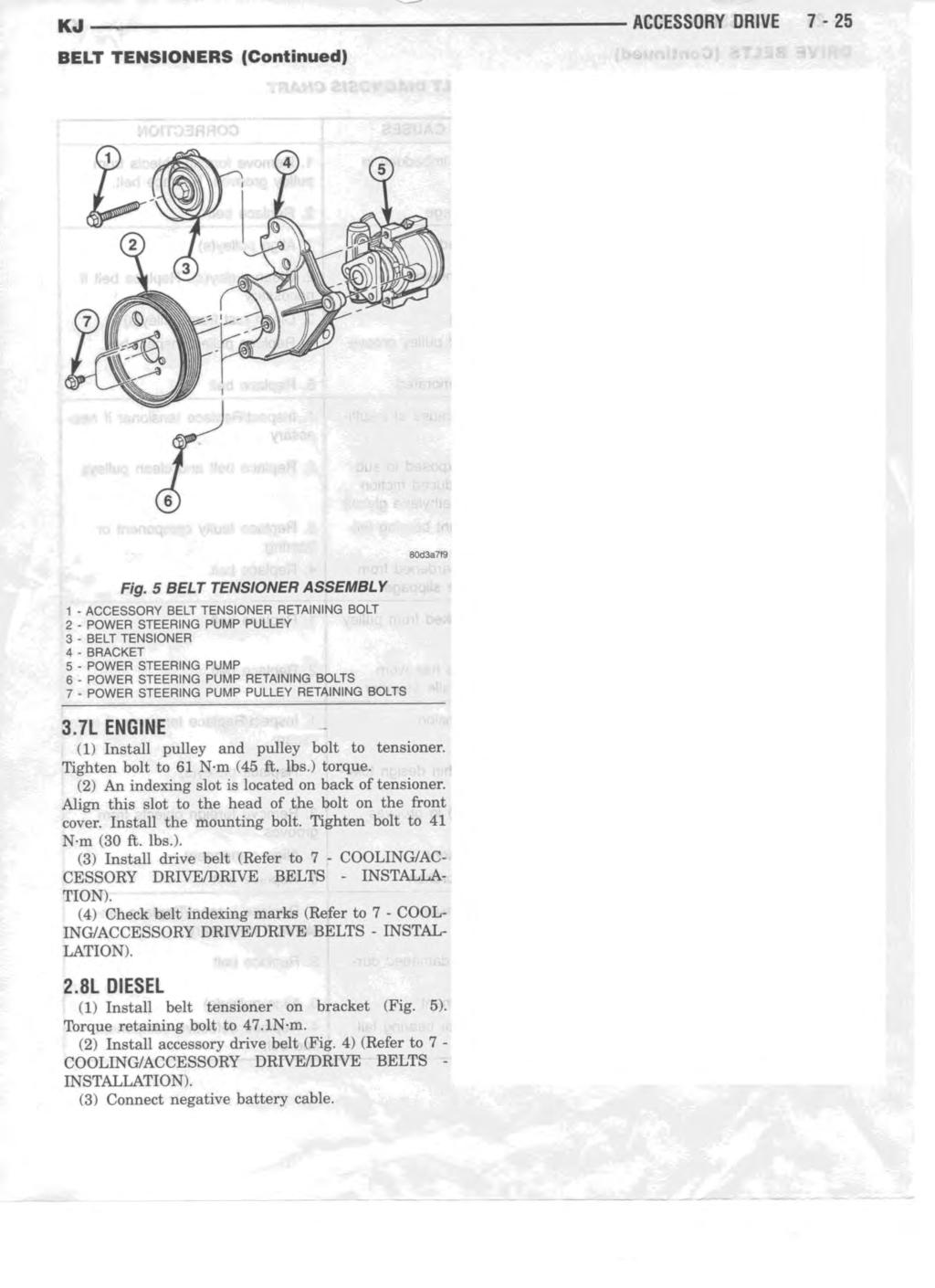
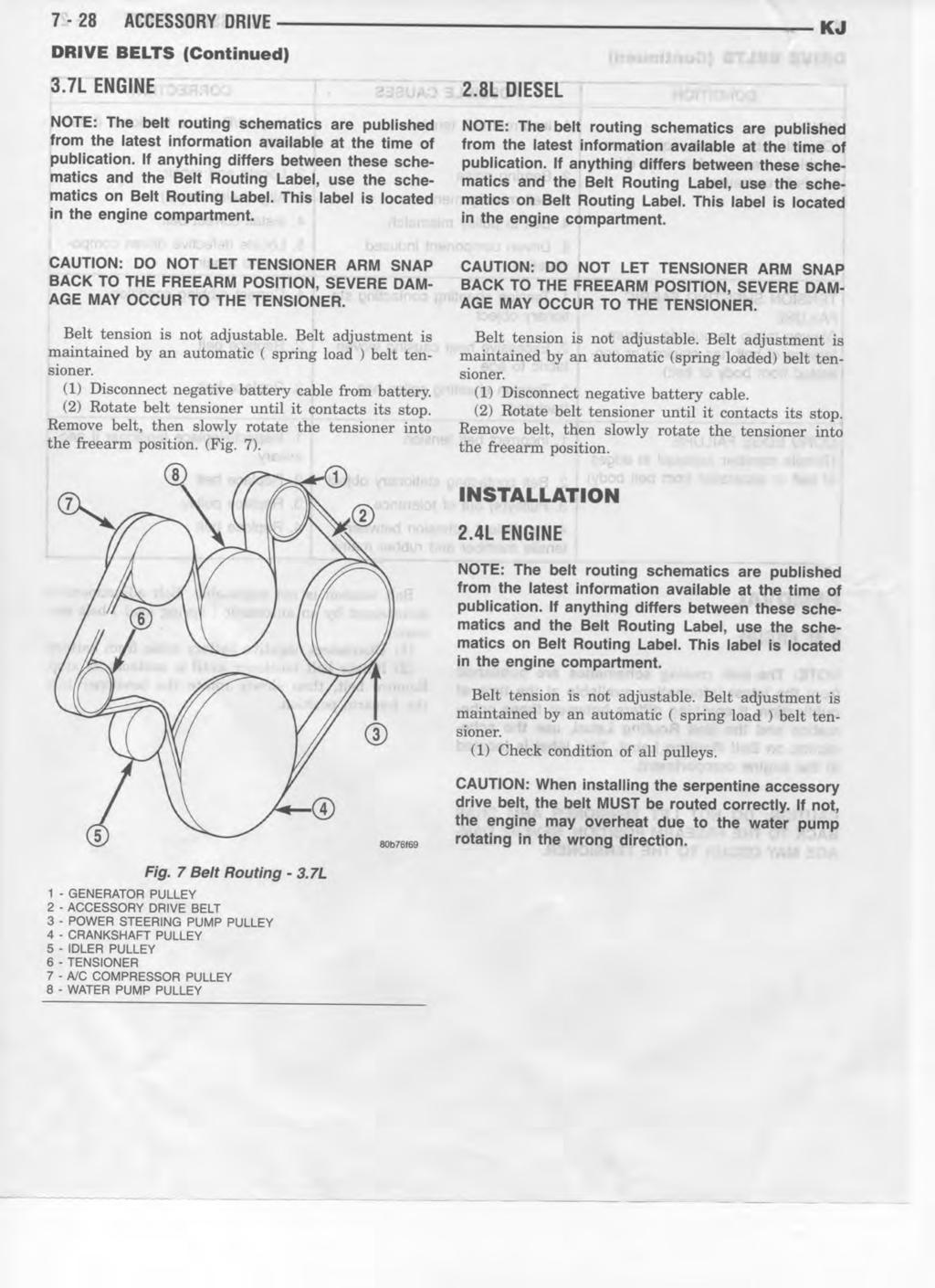
28
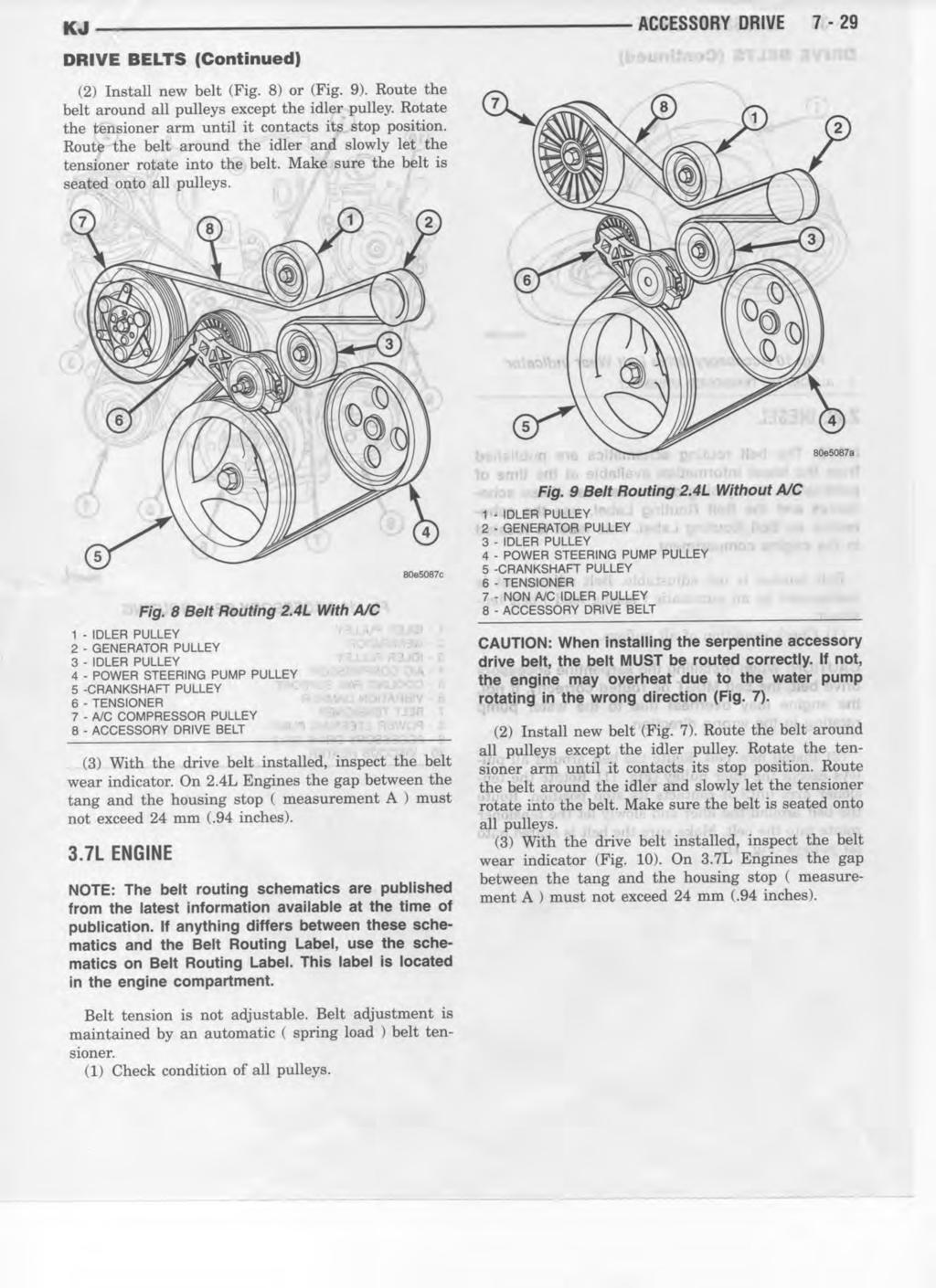
29
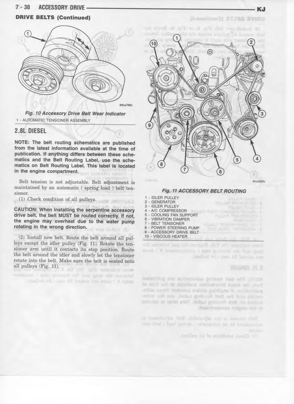
30
31
32
33
34
35
36
37
38
39
40
41
42
43
44
45
46
47
48
49
50
51
52
53
54
55
56
57
58
59
60
61
62 KJ TRANSMISSION 7-45 TRANSMISSION TABLE OF CONTENTS page TRANSMISSION STANDARD PROCEDURE - TRANSMISSION COOLER LINE QUICK CONNECT FITTING DISASSEMBLY/ASSEMBLY...45 page TRANS COOLER DESCRIPTION...46 REMOVAL...46 INSTALLATION...46 TRANSMISSION STANDARD PROCEDURE - TRANSMISSION COOLER LINE QUICK CONNECT FITTING DISASSEMBLY/ASSEMBLY DISCONNECT (1) Remove dust cap by pulling it straight back off of quick connect fitting. (Fig. 1) (2) Place disconnect tool Special Tool 8875A onto transmission cooler line with the fingers of the tool facing the quick connect fitting. (3) Slide disconnect tool down the transmission line and engage the fingers of the tool into the retaining clip. When properly engaged in the clip, the tool will fit flush against the quick connect fitting. (4) Rotate the disconnect tool 60 to expand the retaining clip. (5) While holding the disconnect tool against the quick connect fitting, pull back on the transmission cooler line to remove. Fig. 1 Oil Cooler Line Quick Connect Fitting - Disassembly 1 - QUICK CONNECT FITTING 2 - DUST CAP 3 - OIL COOLER LINE 4 - SPECIAL TOOL 8875A
63 7-46 TRANSMISSION KJ TRANSMISSION (Continued) CONNECT will only snap over quick connect fitting when the transmission cooler line is properly installed. NOTE: If dust cap will not snap into place, repeat assembly step #2. TRANS COOLER DESCRIPTION The automatic transmission cooler is located in the front of the condenser and behind the front fascia. The transmission cooler is a heat exchanger that allows heat in the transmission fluid to be transferred to the air passing over the cooler fins. The transmission oil cooler for the 2.8L Diesel with automatic transmission integrated into the A/C condenser. The Transmission oil cooler assembly is equipped with quick connect fitting for the transmission oil cooler lines. Fig. 2 Oil Cooler Line Quick Connect Fitting - Assembly 1 - QUICK CONNECT FITTING 2 - CLIP 3 - OIL COOLER LINE 4 - DUST CAP (1) Align transmission cooler line with quick connect fitting while pushing straight into the fitting. (2) Push in on transmission cooler line until a click is heard or felt (Fig. 2). (3) Slide dust cap down the transmission cooler line and snap it over the quick connect fitting until it is fully seated and rotates freely (Fig. 2). Dust cap REMOVAL (1) Remove electric cooling fan (Refer to 7 - COOL- ING/ENGINE/RADIATOR FAN - REMOVAL). (2) Position cooling fan out of the way. (3) Using Tool 8875A, disconnect transmission cooler tube from the transmission cooler (Refer to 7 - COOLING/TRANSMISSION - STANDARD PROCE- DURE). (4) Remove the transmission cooler mounting bolts. (5) Remove transmission cooler from vehicle. INSTALLATION (1) Position transmission cooler in vehicle. (2) Install transmission mounting bolts. Tighten to 14 N m (123 in. lbs.) (3) Install transmission cooler lines into cooler (Refer to 7 - COOLING/TRANSMISSION - STAN- DARD PROCEDURE). (4) Install electric cooling fan (Refer to 7 - COOL- ING/ENGINE/RADIATOR FAN - INSTALLATION).
COOLING SYSTEM 7-1 COOLING SYSTEM CONTENTS
 DN COOLING SYSTEM 7-1 COOLING SYSTEM CONTENTS page GENERAL INFORMATION ACCESSORY DRIVE BELT TENSION... 4 COOLANT... 2 COOLANT RESERVE/OVERFLOW SYSTEM... 2 COOLING SYSTEM... 1 COOLING SYSTEM CIRCULATION...
COOLING SYSTEM 7-1 COOLING SYSTEM CONTENTS
 ZJ COOLING SYSTEM 7-1 COOLING SYSTEM CONTENTS page GENERAL INFORMATION ACCESSORY DRIVE BELTS... 2 BLOCK HEATER... 2 COOLANT... 2 COOLING SYSTEM CIRCULATION... 2 COOLING SYSTEM... 1 RADIATOR... 2 WATER
COOLING SYSTEM 7-1 COOLING SYSTEM TABLE OF CONTENTS
 WJ COOLING SYSTEM 7-1 COOLING SYSTEM TABLE OF CONTENTS page DESCRIPTION AND OPERATION AUTOMATIC BELT TENSIONER...7 BELT TENSION...7 COOLANT...3 COOLANT TANK...3 COOLING SYSTEM...1 COOLING SYSTEM HOSES....6
2007 Dodge Nitro R/T ENGINE Cooling - Nitro
 2007 ENGINE Cooling - Nitro DESCRIPTION DESCRIPTION The cooling system regulates engine operating temperature. It allows the engine to reach normal operating temperature as quickly as possible, maintains
A/C SYSTEM GENERAL DIAGNOSTIC PROCEDURES
 Article Text ARTICLE BEGINNING 1993 AIR CONDITIONING & HEAT A/C General Diagnostic Procedures Diagnosis is an important first step in A/C system servicing. To save time and effort, systems should be carefully
COOLING SYSTEM. Return to Main Table of Contents
 COOLING SYSTEM Return to Main Table of Contents GENERAL... 2 COOLING SYSTEM... 7 RADIATOR... 9 ENGINE COOLANT PUMP... 12 THERMOSTAT... 14 ENGINE COOLANT TEMPERATURE SENDER &, SENSOR... 15 ENGINE COOLANT
COOLING SYSTEM 7-1 COOLING SYSTEM TABLE OF CONTENTS
 LH COOLING SYSTEM 7-1 COOLING SYSTEM TABLE OF CONTENTS page DESCRIPTION AND OPERATION COOLING SYSTEM...2 COOLANT...3 COOLANT PERFORMANCE...3 ENGINE THERMOSTAT...3 WATER PUMP...4 RADIATOR...4 COOLING SYSTEM
COOLING GROUP 7 CONTENTS
 A GROUP 7 COOLING CONTENTS Page ACCESSORY BELT DRIVES 8 CONVERSION TABLE 10 ENGINE WATER TEMPERATURE GAUGE. 8 FAN 3 FLUID FAN DRIVE.......... 3 PRESSURE TESTING COOLING SYSTEM. 7 PRESSURE TESTING RADIATOR
k. Components not properly adjusted. Refer to machine technical manual for proper adjustment of components.
 General Troubleshooting Charts General Troubleshooting Charts Use the charts on the following pages to help in listing all the possible causes of trouble when you begin diagnosing and testing of a machine.
Section 10 Chapter 15
 Section 10 Chapter 15 24 Valve, 8.3 Liter Engine Note: All coding used in the 8.3 Liter and 9 Liter engine manuals are Cummins engine codes. These engine codes have no meaning to New Holland warranty codes
ENGINE COOLING SYSTEM
 B ENGINE A SECTION ENGINE COOLING SYSTEM CO C D CONTENTS E PRECAUTIONS... 2 Precautions for Supplemental Restraint System (SRS) AIR BAG and SEAT BELT PRE-TEN- SIONER... 2 Precautions for Liquid Gasket...
GENERAL SPECIFICATIONS 25-2 GENERAL. Water cooling, forced circulation with electric fan
 COOLING SYSTEM GENERAL 2 COOLING SySTEM 8 RADIATOR 10 RADIATOR FAN MOTOR ASSY 12 WATER PUMP 14 THERMOSTAT 16 WATER HOSE AND PiPE 17 WATER TEMPERATURE GAUGE UNIT AND SENSOR 18 GENERAL GENERAL Y25CAOA SPECIFICATIONS
ENGINE COOLING GROUP CONTENTS GENERAL INFORMATION SERVICE SPECIFICATIONS COOLANT SEALANT THERMOSTAT...
 14-1 GROUP 14 CONTENTS GENERAL INFORMATION 14-2 SERVICE SPECIFICATIONS 14-2 COOLANT 14-3 SEALANT 14-3 DIAGNOSIS 14-3 INTRODUCTION 14-3 TROUBLESHOOTING STRATEGY 14-3 SYMPTOM CHART 14-3 SYMPTOM PROCEDURES
ENGINE COOLING SYSTEM
 B ENGINE A SECTION ENGINE COOLING SYSTEM CO C D CONTENTS E PRECAUTIONS... 2 Precautions for Liquid Gasket... 2 REMOVAL OF LIQUID GASKET SEALING... 2 LIQUID GASKET APPLICATION PROCEDURE... 2 PREPARATION...
ENGINE COOLING GROUP CONTENTS GENERAL INFORMATION SERVICE SPECIFICATIONS COOLANT SEALANT THERMOSTAT...
 14-1 GROUP 14 CONTENTS GENERAL INFORMATION 14-2 SERVICE SPECIFICATIONS 14-2 COOLANT 14-3 SEALANT 14-3 DIAGNOSIS 14-3 INTRODUCTION 14-3 TROUBLESHOOTING STRATEGY 14-3 SYMPTOM CHART 14-3 SYMPTOM PROCEDURES
Cooling System. Water Pump. Radiator
 The cooling system is engineered to remove waste heat from the engine cylinder block and cylinder head to prevent damage caused by overheating of those components. The waste heat is transferred through
Antifreeze Type SYC1025 (Long life coolant) Mixing ratio (water:antifreeze) Cooling fan module Type Electric Capacity
 Mixing ratio (water:antifreeze) Cooling fan module Type Electric Capacity") 152000 083 1. SPECIFICATION Unit Description Specification Cooling system Type Water cooling, forced circulation Coolant Capacity approx. 8.5 L Radiator Core size 555W x 582.4H x 27T (over 326,250mm2)
152000 083 1. SPECIFICATION Unit Description Specification Cooling system Type Water cooling, forced circulation Coolant Capacity approx. 8.5 L Radiator Core size 555W x 582.4H x 27T (over 326,250mm2)
DIAGNOSIS MADE EASY PART OF COOLING SYSTEM TROUBLE SHOOTING
 DIAGNOSIS MADE EASY PART OF COOLING SYSTEM TROUBLE SHOOTING DIAGNOSE CAR PROBLEMS QUICKLY AND RELIABLY USING GATES INTUITIVE QUESTION TREE DIAGNOSTIC PROCESS The purpose of this booklet is to provide
ENGINE COOLING SYSTEM
 ENGINE SECTION CO A ENGINE COOLING SYSTEM CO C D CONTENTS E PRECAUTION... 2 PRECAUTIONS... 2 Precaution for Supplemental Restraint System (SRS) "AIR BAG" and "SEAT BELT PRE-TEN- SIONER"...2 Precaution
TC Series Cooling Systems
 TC Series Cooling Systems Table of Contents Table of Contents...1 List of Figures...1 Safety...2 Introduction...2 General Specifications...2 Types of Coolant...2 Routine Maintenance...2 Surge Tank Coolant
COOLING SYSTEM 7-1 COOLING SYSTEM CONTENTS
 Z COOLING SYSTEM 7-1 COOLING SYSTEM CONTENTS page DIAGNOSIS... 2 ENGINE ACCESSORY DRIVE BELTS... 32 ENGINE BLOCK HEATER... 38 page SERVICE PROCEDURES... 6 SPECIFICATIONS... 40 INDEX page Cooling System...
Service Instruction ENGINE COMPONENTS, INC.
 Title: Service Instruction S.I. No.: 89-5-1 Page: 1 of 5 Issued: 05/05/89 Revision: 1 (09/01/01) Technical Portions of FAA DER Approved. FAILURE OF ENGINE TO START 27 points 1. Lack of fuel 2. Ignition
Subject Underhood G System Error Codes and Symptoms System or Parts affected
 System or Parts affected Index Underhood70G (V90Gxxx) System or Parts affected... 1 Overview... 1 Identifying your System... 1 Retrieving Logged Error Messages... 1 Error Messages... 3 Error Message Table...
COOLING SYSTEM Return To Main Table of Contents
 COOLING SYSTEM Return To Main Table of Contents GENERAL.............................................. 2 COOLING SYSTEM........................................... 7 RADIATOR... 8 RADIATOR FAN MOTOR ASSEMBLY...
2011 Focus Workshop Manual. DESCRIPTION AND OPERATION Procedure revision date: 06/24/2010
 SECTION 303-05: Accessory Drive 2011 Focus Workshop Manual DESCRIPTION AND OPERATION Procedure revision date: 06/24/2010 Accessory Drive The accessory drive: has a single serpentine drive belt with 6 ribs.
Engine Compartment Inspection
 Engine Compartment Inspection Unit Contents Student Page Student Components Learning Activities Sheet... 7 3 Abbreviated Checklist.... 7 5 Objective Sheet... 7 7 Expanded Checklist... 7 9 * Job Sheets
ENGINE LUBRICATION & COOLING SYSTEMS SECTIONLC CONTENTS. ENGINE LUBRICATION SYSTEM...2 Precautions...2
 ENGINE LUBRICATION & COOLING SYSTEMS SECTIONLC CONTENTS ENGINE LUBRICATION SYSTEM...2 Precautions...2 LIQUID GASKET APPLICATION PROCEDURE...2 Preparation...2 SPECIAL SERVICE TOOLS...2 Lubrication Circuit...3
26 - COOLING SYSTEM CONTENTS ENGINE COOLING - DESCRIPTION... 3 ENGINE COOLING - OPERATION... 9 COOLING SYSTEM FAULTS... 1
 26 - COOLING SYSTEM CONTENTS Page LAND ROVER V8 DESCRIPTION AND OPERATION ENGINE COOLING - DESCRIPTION... 3 ENGINE COOLING - OPERATION... 9 FAULT DIAGNOSIS COOLING SYSTEM FAULTS... 1 REPAIR COOLANT - DRAIN
ENGINE COOLING SYSTEM
 B ENGINE A SECTION ENGINE COOLING SYSTEM CO C D CONTENTS E PRECAUTIONS... 2 Precautions for Liquid Gasket... 2 REMOVAL OF LIQUID GASKET SEALING... 2 LIQUID GASKET APPLICATION PROCEDURE... 2 PREPARATION...
Applicable vehicles: 2007 Ford Fusion 2007 Ford Milan 2007 Ford MKZ. DIAGNOSIS AND TESTING Procedure revision date: 11/17/2006
 PATH: Diagnostics > Diagnostic Routines > Powertrain > Engine > Engine Cooling Engine Cooling NOTE Applicable vehicles: 2007 Ford Fusion 2007 Ford Milan 2007 Ford MKZ SECTION 303-03: Engine Cooling 2007
Cooling System. Table of Contents
 Sub-Headings Safety 2 s 2 Cautions 2 Notes 2 Introduction 2 General Specifications 2 Engine 2 Coolant 2 Routine Maintenance 2 Hose Connections 4 Radiator, Charge Air and Heater Cores 4 Cooling System Leaks
Module 7: Cooling System Components
 Â ÂÂ Â Basic Cooling System Components Radiators Common Types of Radiators Coolant Hoses Water Pumps Centrifugal Force Types of Drives for Water Pumps Types of Drive Belts Basic Cooling System Components
 Â  Basic Cooling System Components Radiators Common Types of Radiators Coolant Hoses Water Pumps Centrifugal Force Types of Drives for Water Pumps Types of Drive Belts Basic Cooling System Components
CHARGING SYSTEM 8C - 1 CHARGING SYSTEM CONTENTS
 ZG CHARGING SYSTEM 8C - 1 CHARGING SYSTEM CONTENTS page GENERAL INFORMATION OVERVIEW... 1 DESCRIPTION AND OPERATION BATTERY TEMPERATURE SENSOR... 2 CHARGING SYSTEM OPERATION... 1 ELECTRONIC VOLTAGE REGULATOR...
GROUP CONTENTS GENERAL DESCRIPTION RADIATOR SPECIAL TOOL THERMOSTAT ENGINE COOLING DIAGNOSIS...
 14-1 GROUP 14 CONTENTS GENERAL DESCRIPTION 14-2 SPECIAL TOOL 14-2 ENGINE COOLING DIAGNOSIS 14-3 INTRODUCTION 14-3 TROUBLESHOOTING STRATEGY 14-3 SYMPTOM CHART 14-3 SYMPTOM PROCEDURES 14-4 ON-VEHICLE SERVICE
2014 RAM C/V Tradesman
 Fig. 91: Suction Hose Ball Valve NOTE: View typical 14. Open the suction hose's ball valve to begin refilling the cooling system. 15. When the vacuum gauge reads zero, the system is filled. NOTE: On some
DIAGNOSIS AND TESTING
 303-05-1 Accessory Drive 303-05-1 DIAGNOSIS AND TESTING Accessory Drive Inspection and Verification CAUTION: Under no circumstances should the accessory drive belt, tensioner or pulleys be lubricated as
Table 6-1. Problems and solutions with pump operations. No Fluid Delivery
 Table 6-1. and solutions with pump operations No Fluid Delivery Fluid level in the reservoir is low. Oil intake pipe or inlet filter is plugged. Air leak in the inlet line prevents priming or causes noise
 Page 1 of 50 Section 412-00: Climate Control System General Information DIAGSIS AND TESTING 1997 Mark VIII Workshop Manual Climate Control System Special Service Tool(s) 73 Digital Multimeter 105-R0051
SECTION Accessory Drive
 303-05-i Accessory Drive 303-05-i SECTION 303-05 Accessory Drive CONTENTS PAGE DIAGNOSIS AND TESTING Accessory Drive... 303-05-2 Inspection and Verification... 303-05-2 Symptom Chart... 303-05-5 Component
13. FUEL SYSTEM/CARBURETOR/
 13 FUEL SYSTEM/CARBURETOR/FUEL PUMP FUEL SYSTEM --------------------------------------------------------- 13-1 SCHEMATIC DRAWING ---------------------------------------------- 13-2 OPERATION OF CARBURETOR
HEATING & AIR CONDITIONING
 AN HEATING & AIR CONDITIONING 24-1 HEATING & AIR CONDITIONING TABLE OF CONTENTS page HEATING & AIR CONDITIONING DESCRIPTION...1 OPERATION...1 DIAGNOSIS AND TESTING...1 A/C PERFORMANCE...1 DIAGNOSIS AND
ENGINE COOLING SYSTEM
 ENGINE SECTION CO A ENGINE COOLING SYSTEM CO C D CONTENTS E QR25DE PRECAUTION... 3 PRECAUTIONS... 3 Precaution for Supplemental Restraint System (SRS) "AIR BAG" and "SEAT BELT PRE-TEN- SIONER"...3 Necessary
Wiring diagrams on page 29 are for reference only. For detailed vehicle wiring refer to Navistar documents.
 1 10/2014 REV 7 !!Attention!! Before performing diagnostics: Wiring diagrams on page 29 are for reference only. For detailed vehicle wiring refer to Navistar documents. Check for Fault Codes using the
Technical Information and Diagnostic Guide
 Technical Information and Diagnostic Guide This guide will assist you in becoming more familiar with the working components of the NITE System and the proper steps and procedures to completely diagnose
ENGINE COOLING GROUP CONTENTS RADIATOR GENERAL DESCRIPTION SPECIAL TOOLS THERMOSTAT
 14-1 GROUP 14 CONTENTS GENERAL DESCRIPTION 14-2 SPECIAL TOOLS 14-3 DIAGNOSIS 14-3 INTRODUCTION 14-3 TROUBLESHOOTING STRATEGY 14-3 SYMPTOM CHART 14-4 SYMPTOM PROCEDURES 14-4 ON-VEHICLE SERVICE 14-17 ENGINE
Powertrain DTC Summaries EOBD
 Powertrain DTC Summaries Quick Reference Diagnostic Guide Jaguar X-TYPE 2.0 L 2002.25 Model Year Refer to page 2 for important information regarding the use of Powertrain DTC Summaries. Jaguar X-TYPE 2.0
2005 Chevrolet Equinox LS ENGINE Engine Cooling - Equinox
 2005 ENGINE Engine Cooling - Equinox SPECIFICATIONS FASTENER TIGHTENING SPECIFICATIONS Fastener Tightening Specifications Specification Application Metric English Coolant Heater 50 N.m 37 lb ft Heater
Section 10 Chapter 7
 Section 10 Chapter 7 24 Valve, 8.3 Liter Engine Troubleshooting Symptoms Identification Note: All coding used in the 8.3 Liter and 9 Liter engine manuals are Cummins engine codes. These engine codes have
AIR CONDITIONING SYSTEM
 AC-1 AIR CONDITIONING SYSTEM GENERAL INFORMATION DESCRIPTION TROUBLESHOOTING PREPARATION REFRIGERATION SYSTEM DRIVE BELT REFRIGERATION LINES COMPRESSOR RECEIVER CONDENSOR COOLING UNIT COOL/ICE BOX EVAPORATORS
COMPRESSORS REPLACEMENT PROCEDURE
 COMPRESSORS REPLACEMENT PROCEDURE INTRODUCTION Shown below, you can find the procedure that you must follow to replace compressors. INSTALLATION INSTRUCTION Steps to follow: 1) Remove the damaged compressor
HEATING & AIR CONDITIONING
 VA HEATING & AIR CONDITIONING 24-1 HEATING & AIR CONDITIONING TABLE OF CONTENTS page HEATING & AIR CONDITIONING DESCRIPTION...1 OPERATION...2 DIAGNOSIS AND TESTING A/C PERFORMANCE...3 HEATER PERFORMANCE
The engine control module (ECM) uses the following information to calculate an expected airflow rate.
 uses the following information to calculate an expected airflow rate.") DTC Descriptors DTC Mass Air Flow (MAF) sensor performance Circuit/System Description The engine control module (ECM) uses the following information to calculate an expected airflow rate. The throttle
DTC Descriptors DTC Mass Air Flow (MAF) sensor performance Circuit/System Description The engine control module (ECM) uses the following information to calculate an expected airflow rate. The throttle
DESCRIPTION AND OPERATION
 Page 1 of 10 DESCRIPTION AND OPERATION AIR DELIVERY DESCRIPTION AND OPERATION The air delivery description and operation is divided into five areas: HVAC Control Components Air Speed Air Delivery Recirculation
A/C-HEATER SYSTEM - AUTOMATIC
 A/C-HEATER SYSTEM - AUTOMATIC 1988 Toyota Celica 1988 Automatic A/C-Heater Systems Celica * PLEASE READ THIS FIRST * CAUTION: When discharging air conditioning system, use only approved refrigerant recovery/recycling
Lubrication & Cooling Systems
 Study Guide Chapter 14 Pages 393 432 44 Points 1. The life span of an engine depends largely upon its & systems. Lube & Cooling The American Petroleum Institute (API) rates oil service classification.
DIAGNOSIS AND TESTING
 412-00-1 Climate Control System - General Information 412-00-1 DIAGNOSIS AND TESTING Climate Control System Refer to Wiring Diagrams Cell 54, Air Conditioning/Heater for schematic and connector information.
SECTION Climate Control System - General Information
 412-00-i Climate Control System - General Information 412-00-i SECTION 412-00 Climate Control System - General Information CONTENTS PAGE DIAGNOSIS AND TESTING Climate Control System... 412-00-2 Inspection
Active Grille Air Shutter 1 Malfunction
 Page 1 of 5 Active Grille Air Shutter 1 Malfunction 2015 Cadillac ATS 2.0L Eng Premium Print Date: Diagnostic Instructions Perform the Diagnostic System Check - Vehicle prior to using this diagnostic procedure.
Troubleshooting the Transmission Hydraulic System
 Testing and Adjusting IT28F INTEGRATED TOOLCARRIER POWER TRAIN Testing And Adjusting Introduction Reference: For Specifications with illustrations, refer to SENR5974, IT28F Integrated Toolcarrier Power
SECTION AIR INTAKE SYSTEM
 09-500.295/ 1 2007AL05 SECTION 09-500.295 AIR INTAKE Air for the engine is taken in through a grille located on the upper-rear, left-hand side of the vehicle. See Figure 1. Air passes through a chamber,
FUEL SYSTEM/CARBURETOR/FUEL PUMP
 13 FUEL SYSTEM/CARBURETOR/FUEL PUMP FUEL SYSTEM-------------------------------------------------------------------------------------13-1 SCHEMATIC DRAWING-------------------------------------------------------------------------13-2
COOLING SYSTEM ON-VEHICLE INSPECTION CO 1
 Radiator Cap Tester 2AZ-FE OLING OLING SYSTEM A112194E01 A112306 OLING SYSTEM ON-VEHICLE INSPECTION 1 1. CHECK OLING SYSTEM FOR LEAKS (a) Remove the radiator reservoir cap. CAUTION: To avoid the danger
 Page 1 of 54 412-00 Climate Control System General Information and Diagnostics 2006 Crown Victoria/Grand Marquis DIAGNOSIS AND TESTING Procedure revision date: 12/23/2008 Climate Control System Printable
Cooling system components, removing and installing
 Page 1 of 40 19-1 Cooling system components, removing and installing WARNING! The cooling system is pressurized when the engine is warm. When opening the expansion tank, wear gloves and other appropriate
Powertrain DTC Summaries OBD II
 Powertrain DTC Summaries Quick Reference Diagnostic Guide Jaguar X-TYPE 2.5L and 3.0L 2002 Model Year Revised January, 2002: P0706, P0731, P0732, P0733, P0734, P0735, P0740, P1780 POSSIBLE CAUSES Revised
5220, 5320, 5420, and 5520 Tractor Operation and Test
 5220, 5320, 5420, and 5520 Tractor Operation and Test TECHNICAL MANUAL 5220, 5320, 5420, and 5520 Tractor Operation and Test TM2049 18MAR02 (ENGLISH) For complete service information also see: 5220, 5320,
ENGINE COOLING Click on the applicable bookmark to selected the required model year
 ENGINE COOLING - ENGINE COOLING General Information/ Service Specifications/Lubricant/Sealants GENERAL INFORMATION 0000 The cooling system is designed to keep every part of the engine at appropriate temperature
DTC P0300-P0308. Diagnostic Instructions. DTC Descriptors. Circuit/System Description. Conditions for Running the DTC
 Page 1 of 5 2009 GMC Truck Sierra - 2WD Sierra, Silverado (VIN C/K) Service Manual Engine Engine Mechanical - 4.8L, 5.3L, 6.0L, 6.2L, or 7.0L Description and Operation DTC P0300-P0308 Diagnostic Instructions
Jeep Wrangler TJ 4.0 LITER Installation instructions
 www.jeepair.com 2000-2001 Jeep Wrangler TJ 4.0 LITER Installation instructions Important information about your system, and warranty DO NOT ADD ANY OIL TO ANY PART OF THE SYSTEM. DO NOT USE THE SIGHT GLASS
MANUAL CONTROL / SEMIAUTO TEMPERATURE CONTROL HEATING, VENTILATION AND AIR CONDITIONING SYSTEM
 SECTION 7C MANUAL CONTROL / SEMIAUTO TEMPERATURE CONTROL HEATING, VENTILATION AND AIR CONDITIONING SYSTEM CAUTION: Disconnect the negative battery cable before removing or installing any electrical unit
TSB #: 53 Date: 2/11/2011 HOLDEN (DELPHI) VARIABLE STROKE COMPRESSOR DIAGNOSIS STEP ACTION RESULT YES NO
 VARIABLE STROKE COMPRESSOR DIAGNOSIS STEP ACTION RESULT YES NO") HOLDEN (DELPHI) VARIABLE STROKE COMPRESSOR DIAGSIS TSB #: 53 Date: 2/11/2011 Initial Once Read: Even though the Holden variable stroke compressor manufactured by Delphi has been in the Australian market
HOLDEN (DELPHI) VARIABLE STROKE COMPRESSOR DIAGSIS TSB #: 53 Date: 2/11/2011 Initial Once Read: Even though the Holden variable stroke compressor manufactured by Delphi has been in the Australian market
12. CARBURETOR/FUEL PUMP
 12 CARBURETOR/FUEL PUMP SERVICE INFORMATION... 12-2 TROUBLESHOOTING... 12-2 THROTTLE VALVE DISASSEMBLY... 12-3 THROTTLE VALVE INSTALLATION... 12-4 CARBURETOR REMOVAL... 12-5 AUTO BYSTARTER... 12-6 FLOAT
ENGINE COOLING SYSTEM
 B ENGINE A SECTION ENGINE COOLING SYSTEM CO C D CONTENTS E PRECAUTIONS... 2 Precautions for Supplemental Restraint System (SRS) AIR BAG and SEAT BELT PRE-TEN- SIONER... 2 Precautions for Liquid Gasket...
Trouble Shooting Guide EWA, 3-phase (D2422)
") Trouble Shooting Guide EWA, 3-phase (D2422) Trouble Shooting Guide Problem Possible Cause Possible Remedy Unit does not start Breaker tripped, no power to unit Loose wire Defective contactor or coil Close
Trouble Shooting Guide EWA, 3-phase (D2422) Trouble Shooting Guide Problem Possible Cause Possible Remedy Unit does not start Breaker tripped, no power to unit Loose wire Defective contactor or coil Close
Powertrain DTC Summaries EOBD
 Powertrain DTC Summaries Quick Reference Diagnostic Guide Jaguar S-TYPE V6, V8 N/A and V8 SC 2002.5 Model Year Refer to pages 2 9 for important information regarding the use of Powertrain DTC Summaries.
of premature failure. Remanufactured performance can compromise the system, reduce cooling capability and cause damage to the engine.
 Hub Attached to the bearing assembly is the hub which is the connecting source of power for impeller rotation. Bearing Assembly The bearing assembly is the mechanical support for continuous rotation of
Single Stage Rotary Vane Vacuum Pump Installation and Operation Manual RX-40 RX-63 RX-100
 V acuum Pumps Single Stage Rotary Vane Vacuum Pump Installation and Operation Manual RX-40 RX-63 RX-100 www.republicsales.com Revised 02.15 2015 Republic Sales & Manufacturing Single Stage Rotary Vane
Cooling system components, removing and installing
 19-1 Cooling system components, removing and installing Note: When the engine is warm the cooling system is under pressure. If necessary release pressure before starting repair work. Hoses are secured
CARBURETOR SERVICE INFORMATION TROUBLESHOOTING THROTTLE VALVE DISASSEMBLY THROTTLE VALVE INSTALLATION...
 11 CARBURETOR SERVICE INFORMATION... 11-2 TROUBLESHOOTING... 11-2 THROTTLE VALVE DISASSEMBLY... 11-3 THROTTLE VALVE INSTALLATION... 11-4 CARBURETOR REMOVAL... 11-5 AUTO BYSTARTER... 11-6 FLOAT CHAMBER...
2002 Jeep Grand Cherokee Laredo
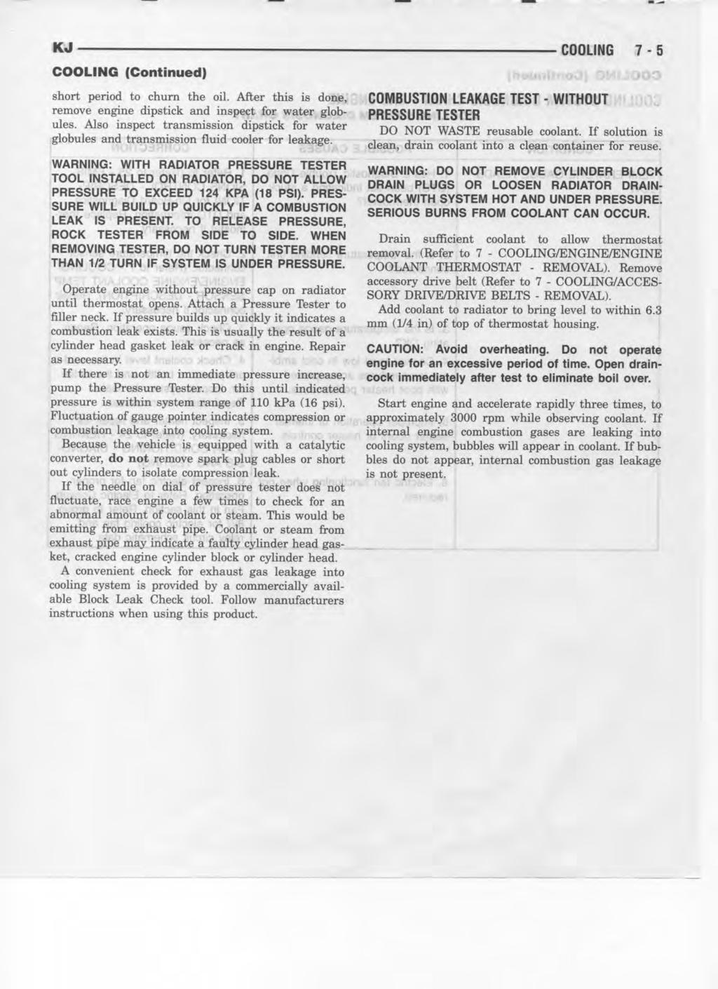
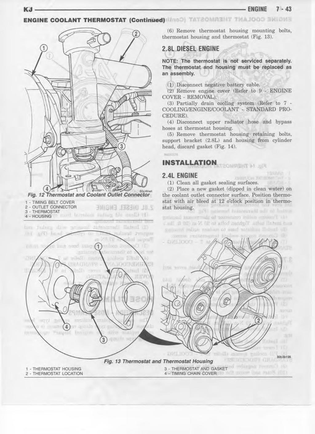
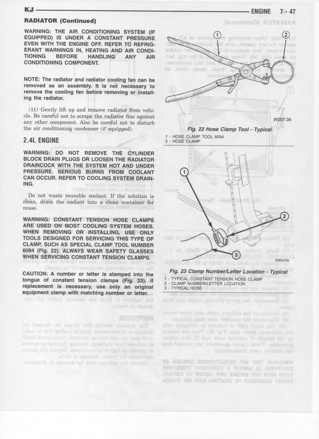
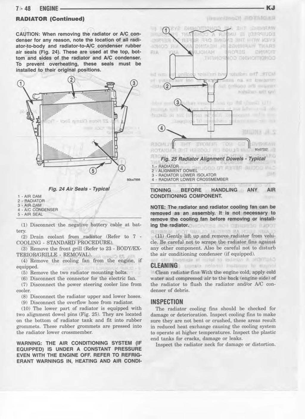
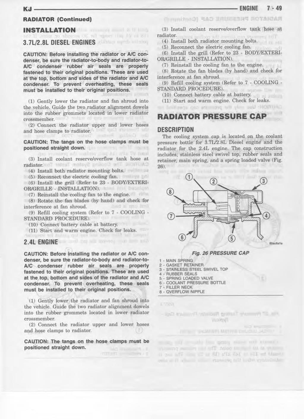
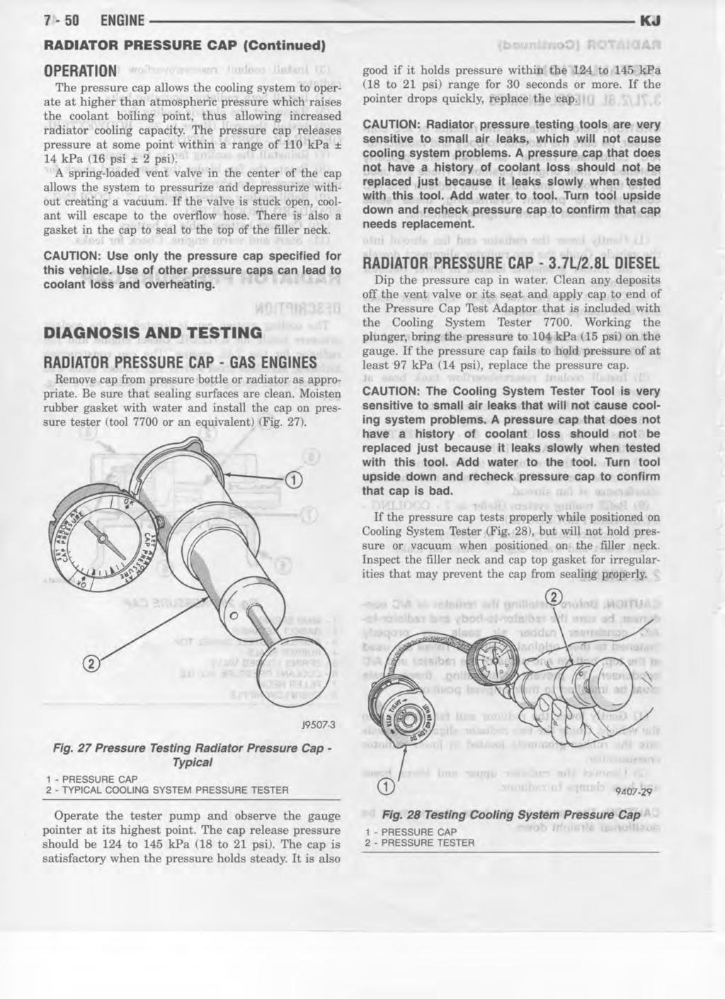
 Removal WARNING: DO NOT REMOVE THE CYLINDER BLOCK DRAIN PLUGS OR LOOSEN THE RADIATOR DRAINCOCK WITH THE SYSTEM HOT AND UNDER PRESSURE. SERIOUS BURNS FROM COOLANT CAN OCCUR. REFER TO COOLING SYSTEM DRAINING.
ALTERNATOR REQUESTED INFORMATION. Vehicles With Dual Generator [ Engine Mount - LH ] 2007 Ford Pickup 6.0L Eng F350 Super Duty
![ALTERNATOR REQUESTED INFORMATION. Vehicles With Dual Generator [ Engine Mount - LH ] 2007 Ford Pickup 6.0L Eng F350 Super Duty](/thumbs/72/66590437.jpg "ALTERNATOR REQUESTED INFORMATION. Vehicles With Dual Generator [ Engine Mount - LH ] 2007 Ford Pickup 6.0L Eng F350 Super Duty") ALTERNATOR 2007 Ford Pickup 6.0L Eng F350 Super Duty REQUESTED INFORMATION Vehicles With Dual Generator [ Engine Mount - LH ] Fig 1: Rotating Drive Belt Tensioner Clockwise 1. Remove the accessory drive
ALTERNATOR 2007 Ford Pickup 6.0L Eng F350 Super Duty REQUESTED INFORMATION Vehicles With Dual Generator [ Engine Mount - LH ] Fig 1: Rotating Drive Belt Tensioner Clockwise 1. Remove the accessory drive
ENGINE COOLING SYSTEM
 ENGINE COOLING SYSTEM B ENGINE SECTION CO A ENGINE COOLING SYSTEM CO C D CONTENTS E PRECAUTIONS... 2 Precautions for Supplemental Restraint System (SRS) AIR BAG and SEAT BELT PRE-TEN- SIONER... 2 Precautions
ENGINE LUBRICATION & COOLING SYSTEMS SECTIONLC CONTENTS IDX. ENGINE LUBRICATION SYSTEM...2 Precautions...2
 ENGINE LUBRICATION & COOLING SYSTEMS SECTIONLC GI MA EM EC CONTENTS FE ENGINE LUBRICATION SYSTEM...2 Precautions...2 SUPPLEMENTAL RESTRAINT SYSTEM (SRS) AIR BAG AND SEAT BELT PRE-TENSIONER...2 LIQUID GASKET
DX: Engine Coolant Temperature (ECT) Sensor
 Sensor") 2009 PCED Gasoline Engines SECTION 5: Pinpoint Tests Procedure revision date: 12/10/2008 DX: Engine Coolant Temperature (ECT) Sensor DX: Introduction DX1 CHECK FOR DIAGNOSTIC TROUBLE CODES (DTCS) Are DTCs
2009 PCED Gasoline Engines SECTION 5: Pinpoint Tests Procedure revision date: 12/10/2008 DX: Engine Coolant Temperature (ECT) Sensor DX: Introduction DX1 CHECK FOR DIAGNOSTIC TROUBLE CODES (DTCS) Are DTCs
SECTION A Engine Cooling
 303-03A-i Engine Cooling 303-03A-i SECTION 303-03A Engine Cooling CONTENTS PAGE DESCRIPTION AND OPERATION Engine Cooling... 303-03A-2 Coolant Flow Diagram... 303-03A-3 303-03A-2 Engine Cooling 303-03A-2
ENGINE 9-1 ENGINE TABLE OF CONTENTS
 WJ ENGINE 9-1 ENGINE TABLE OF CONTENTS page DESCRIPTION AND OPERATION ENGINE IDENTIFICATION...1 HYDRAULIC TAPPETS...2 DIAGNOSIS AND TESTING SERVICE DIAGNOSIS DIESEL MECHANICAL....9 SERVICE DIAGNOSIS DIESEL
Caterpillar Engine 01.00
 Caterpillar Engine 01.00 Engine Port Diagrams Engine Port Diagrams Use the following diagrams to identify engine ports: For a Caterpillar CFE engine, see Fig. 1. For a Caterpillar C-7/C-9 and C-11/C-13
Cooling system Type Water cooling, forced circulation Coolant Capacity Approx. 8.0 ~ 8.5 L
 211201 083 1. SPECIFICATION Description Specification Cooling system Type Water cooling, forced circulation Coolant Capacity Approx. 8.0 ~ 8.5 L Radiator Core size 740W X 378.9H X 27T Flow type Cross flow
22-1 GROUP 22 MANUAL TRANSAXLE CONTENTS MANUAL TRANSAXLE... 22A MANUAL TRANSAXLE OVERHAUL... 22B
 22-1 GROUP 22 MANUAL TRANSAXLE CONTENTS............................... 22A OVERHAUL..................... 22B 22A-2 GROUP 22A MANUAL TRANSAXLE CONTENTS GENERAL DESCRIPTION......... 22A-3 DIAGNOSIS 22A-6
ENGINE LUBRICATION & COOLING SYSTEMS SECTIONLC CONTENTS IDX KA24DE. Radiator ENGINE LUBRICATION SYSTEM...3 Precautions...
 ENGINE LUBRICATION & COOLING SYSTEMS SECTIONLC GI MA EM EC CONTENTS FE KA24DE ENGINE LUBRICATION SYSTEM...3 Precautions...3 SUPPLEMENTAL RESTRAINT SYSTEM (SRS) AIR BAG AND SEAT BELT PRE-TENSIONER...3 LIQUID
Cooling System Description and Operation
 Page 1 of 5 2008 Holden VE Sedan VE, WM, Caprice, Statesman, Lumina, Omega, VXR8 Service Manual Engine Engine Cooling Description and Operation Document ID: 1990377 Cooling System Description and Operation
GROUP 13C 13C-1 CONTENTS GENERAL DESCRIPTION... 13C-2 FUEL TANK... 13C-11 FUEL SUPPLY DIAGNOSIS... 13C-3 SPECIAL TOOLS... 13C-8
 13C-1 GROUP 13C CONTENTS GENERAL DESCRIPTION......... 13C-2 DIAGNOSIS....... 13C-3 INTRODUCTION TO DIAGNOSIS........................ 13C-3 TROUBOLESHOOTING STRATEGY..... 13C-3 SYMPTOM CHART...................
DESCRIPTION AND OPERATION
 412-03-1 Air Conditioning 412-03-1 DESCRIPTION AND OPERATION Air Conditioning Refrigerant flow into the evaporator core is metered The air conditioning system components are: by an evaporator core orifice
CHARGING SYSTEM 8C - 1 CHARGING SYSTEM CONTENTS
 TJ CHARGING SYSTEM 8C - 1 CHARGING SYSTEM CONTENTS page DESCRIPTION AND OPERATION BATTERY TEMPERATURE SENSOR... 2 CHARGING SYSTEM OPERATION... 1 ELECTRONIC VOLTAGE REGULATOR... 2 GENERATOR... 1 DIAGNOSIS
DIAGNOSTIC TROUBLE CODE CHART
 DIAGNOSTIC TROUBLE CODE CHART HINT: DI231 Parameters listed in the chart may not be exactly the same as your readings due to the type of instrument or other factors. If a malfunction code is displayed
GROUP 35A 35A-1 CONTENTS GENERAL DESCRIPTION... 35A-3 BASIC BRAKE SYSTEM DIAGNOSIS 35A-6 HYDRAULIC BRAKE BOOSTER (HBB) DIAGNOSIS...
 DIAGNOSIS...") 35A-1 GROUP 35A CONTENTS GENERAL DESCRIPTION......... 35A-3 DIAGNOSIS 35A-6 INTRODUCTION..................... 35A-6 DIAGNOSTIC TROUBLESHOOTING STRATEGY......................... 35A-6 SYMPTOM CHART...................
35A-1 GROUP 35A CONTENTS GENERAL DESCRIPTION......... 35A-3 DIAGNOSIS 35A-6 INTRODUCTION..................... 35A-6 DIAGNOSTIC TROUBLESHOOTING STRATEGY......................... 35A-6 SYMPTOM CHART...................
Failure Mode Analysis
 Presented by: Brunno Covolan Pg. 1 : Introduction What is Failure Mode Analysis? Looking at the compressor to determine what was the cause of the failure. Why do we need to conduct Failure Mode Analysis?
Different oils are used in automotive A/C systems, based on the type of refrigerant. Polyalkylene Glycol (PAG) oil is used for R-134a refrigerant.
 oil is used for R-134a refrigerant.") Lubricants Automotive air conditioning lubricants are specially formulated because of how and where they operate. Air conditioning oils must be dry (having little or no water content) and mix with the
Lubricants Automotive air conditioning lubricants are specially formulated because of how and where they operate. Air conditioning oils must be dry (having little or no water content) and mix with the
BASIC BRAKE SYSTEM GROUP 35A 35A-1 CONTENTS GENERAL DESCRIPTION... 35A-3 BASIC BRAKE SYSTEM DIAGNOSIS 35A-6
 35A-1 GROUP 35A BASIC BRAKE SYSTEM CONTENTS GENERAL DESCRIPTION......... 35A-3 DIAGNOSIS 35A-6 INTRODUCTION..................... 35A-6 DIAGNOSTIC TROUBLESHOOTING STRATEGY......................... 35A-6
01 02B ON-BOARD DIAGNOSTIC [ENGINE CONTROL SYSTEM (FS)]
![01 02B ON-BOARD DIAGNOSTIC [ENGINE CONTROL SYSTEM (FS)]](/thumbs/80/80600627.jpg "01 02B ON-BOARD DIAGNOSTIC [ENGINE CONTROL SYSTEM (FS)]") ON-BOARD DIAGNOSTIC [ENGINE CONTROL SYSTEM (FS)] CONTROL SYSTEM WIRING DIAGRAM [FS]............................ 2 CONTROL SYSTEM DEVICE AND CONTROL RELATIONSHIP CHART [FS]........ 4 Engine Control System............
ON-BOARD DIAGNOSTIC [ENGINE CONTROL SYSTEM (FS)] CONTROL SYSTEM WIRING DIAGRAM [FS]............................ 2 CONTROL SYSTEM DEVICE AND CONTROL RELATIONSHIP CHART [FS]........ 4 Engine Control System............