W I N T E K WINTEK BOOSTED LIQUID RING VACUUM SYSTEM SN: SYSTEM SUMMARY
|
|
|
- Briana Caldwell
- 5 years ago
- Views:
Transcription
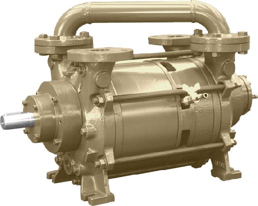
1 W I N T E K C O R P O R A T I O N Customer: HD Microsystems PO#: WINTEK BOOSTED LIQUID RING VACUUM SYSTEM SN: SYSTEM SUMMARY Requirements Application Multiple Use: General House vacuum, Dryers, Filters Design Suction Pressure 2 torr (2-50 torr range) Design Suction temperature 78 o F Capacity Requirement 4.8 lbs/hr air = ~400 ACFM Vapors / Solvents Not provided (assume air/water) Vacuum Control By DVT/Wintek Area Classification 3/60/460 TEFC/ Nema 12 Coolant Available 50 o F Materials of Construction Standard (CS, Copper, Viton, Buna) WINTEK Boosted Water Sealed Liquid Ring Vacuum System model-b400/aj/wss-250/2-1fr This is a boosted liquid ring vacuum system with air jet, which utilizes a water sealed liquid ring vacuum pump for the final stage. Rotary Lobe Blower Model B-400 CI construction with carbon faced mechanical seals. The booster is driven by a 7.5 HP, 3/60/460 Volt, direct drive, foot-mounted, TEFC motor. Booster bypass, booster offset inlet, pneumatic bypass valve High temperature safety switch, set to 325 o F On/Off operation controlled by PIT and panel (50 Torr cut in/60 Torr shut off) Bellows flex discharge, with outer mesh guard Discharge temperature gauge Cooling coils in the end covers Air jet, CI, non-code, heat tracing with insulation Air jet bypass, pneumatic bypass valve Pneumatic actuated motive air valve piped to separator tank, N4 On/Off operation controlled by PIT and panel, 9 Torr cut in/out Liquid Ring Vacuum Pump, DVT model DV0251B- DA3, two stage liquid ring pump constructed in cast iron housing, SS impeller and shaft, mechanical seals with viton elastomers. The pump is coupling driven by a 20 HP, 3/60/460V, TEFC motor. Vacuum gauge Inlet check valve suitable for vacuum service Anti-Cavitation valve Inlet isolation valve Sealant Recirculation Components Vacuum System Design at a Higher Level 230 US Hwy 206, Suite 401, Flanders, NJ Ph: (973) Fax: (973) Website:
2 W I N T E K C O R P O R A T I O N WINTEK BOOSTED LIQUID RING VACUUM SYSTEM SN: SYSTEM SUMMARY Separator tank 316SS construction, tangential inlet, non-code, removable top, internal demister. All sealant recirculation line components are SS. Manual drain valve, oversized Low level switch Make up solenoid Protected level gauge (w/ cleanouts), Sealant stop valve Y-strainer Back pressure orifice o Sealant heat exchanger, non code, Cu tubes, CS remainder, requires 50 o F cooling fluid Flow switch, paddle type Sealant flow adjusting valve Compound gauge Temperature gauge Set of CS vapor piping Multi mode control panel - Nema 12 (460), includes IEC starters for each pump, control transformers, Run lights, high temp light, low flow light, HOA selector switch for booster, high temp switch, booster and air jet bypass valve circuit, skid mounted, pre-wired. Panel mode logics allow vacuum system to operate during the dry vacuum requirements, as a booster air jet-liquid ring system, or for the house vacuum application, only the two-stage liquid ring pump. Vacuum System Design at a Higher Level 230 US Hwy 206, Suite 401, Flanders, NJ Ph: (973) Fax: (973) Website:
3 W I N T E K C O R P O R A T I O N WINTEK BOOSTED LIQUID RING VACUUM SYSTEM SN: SYSTEM SUMMARY Air Jet Process Inlet Booster Liquid Ring Vacuum Pump Separator Tank Vapor Discharge* Cooling Water Out Cooling Water In Control Panel Sealant Heat Exchanger *May contain Process Vapors. Pipe Appropriately. Vacuum System Design at a Higher Level 230 US Hwy 206, Suite 401, Flanders, NJ Ph: (973) Fax: (973) Website:

4 W I N T E K C O R P O R A T I O N WINTEK BOOSTED LIQUID RING VACUUM SYSTEM SN: SYSTEM SUMMARY Inlet Check Valve Inlet Isolation Valve Anti-Cavitation Valve Vacuum Gauge 2 nd Stage Anti- Cavitation Valve Sealant Temp. Gauge Flow Switch Compound Gauge Sealant Adjusting Valve Vacuum System Design at a Higher Level 230 US Hwy 206, Suite 401, Flanders, NJ Ph: (973) Fax: (973) Website:
 252-8200 Fax: (973) 252-8233 Website: www.")
5 W I N T E K C O R P O R A T I O N WINTEK BOOSTED LIQUID RING VACUUM SYSTEM SN: SYSTEM SUMMARY Overflow Port* Level Glass Clean Out Ports Y-Strainer w/ Blow Down Valve *May contain Process. Pipe Appropriately. Vacuum System Design at a Higher Level 230 US Hwy 206, Suite 401, Flanders, NJ Ph: (973) Fax: (973) Website:
 252-8200 Fax: (973) 252-8233 Website: www.")
6 W I N T E K C O R P O R A T I O N WINTEK BOOSTED LIQUID RING VACUUM SYSTEM SN: SYSTEM SUMMARY Booster Bypass Valve Air Jet Bypass Valve Motive Air Isolation Valve Vacuum System Design at a Higher Level 230 US Hwy 206, Suite 401, Flanders, NJ Ph: (973) Fax: (973) Website:
 252-8200 Fax: (973) 252-8233 Website: www.")
7 W I N T E K C O R P O R A T I O N WINTEK BOOSTED LIQUID RING VACUUM SYSTEM SN: SYSTEM SUMMARY Sealant Make-up Solenoid Valve Drain Valve* Level Switch *May contain Process. Pipe Appropriately. Vacuum System Design at a Higher Level 230 US Hwy 206, Suite 401, Flanders, NJ Ph: (973) Fax: (973) Website:
 Vacuum System Design at a Higher Level 230 US Hwy 206, Suite 401, Flanders, NJ 07836 Ph: (973) 252-8200 Fax: (973) 252-8233 Website: www.")
8 W I N T E K C O R P O R A T I O N WINTEK BOOSTED LIQUID RING VACUUM SYSTEM SN: SYSTEM SUMMARY Pressure Indicating Transmitter (PIT) (Behind Inlet Piping) Booster Discharge Temp. Gauge (high temp. switch on opposite side) Vacuum System Design at a Higher Level 230 US Hwy 206, Suite 401, Flanders, NJ Ph: (973) Fax: (973) Website:
9 W I N T E K C O R P O R A T I O N Sealant WINTEK BOOSTED LIQUID RING VACUUM SYSTEM SN: SYSTEM SUMMARY OPERATIONAL NOTES The sealant is the liquid in the pump which is used to create vacuum. (See How a Liquid Ring Pump Works ) The sealant temperature and composition directly affects the capacity of the liquid ring pump. An increase in the temperature of the sealant leads to an increase of the vapor pressure of the sealant, and thus the sealant vapor will occupy more of the pump. The physical capacity of the liquid ring pump is fixed based upon the volume between the impeller blades. A sealing liquid with a higher vapor pressure occupies a greater portion of this volume thus reducing the overall capacity of the pump. Sealant Recirculation The sealant circulation system provides total recirculation of the sealing liquid (water or process solvent) due the differential pressure between the vacuum pump (vacuum) and the separator (atmosphere). The sealant circulation rates are achieved when a vacuum level of HgV is attained. If your process equipment to be evacuated is very large, or if your process operation requires less than HgV, the proper sealant rate may not be attained within the time period for the flow switch. In these cases either a circulation pump can be added; or a backpressure orifice may be included in your system. In the case of a backpressure orifice, then open draining of the sealant thru the overflow connection cannot be utilized, and a valve should be installed on the overflow. A heat exchanger is used to remove the heat of compression in the sealing liquid before it is reintroduced into the liquid ring pump. After the liquid has passed through the exchanger it is now suitable for reuse and may be again used as sealant for the liquid ring pump. System Sealant Levels The vacuum pump should not be started without some liquid in the vacuum pump- it should be half full of liquid. Do not start the vacuum pump in a flooded condition (where the vacuum pump is completely full of liquid, as this may damage the pump- liquid does not compress). It is imperative to check the sealant water level before the initial starting of the vacuum system, as it may have been drained before shipment. If the system has been fully drained, re-priming of the vacuum pump may be necessary by dumping 1-2 gallons of liquid into the inlet of the vacuum pump, before starting the pump. Once the vacuum pump has been operated after installation, repriming will not be necessary, unless the system has been drained. Be sure to check the sealant level in the liquid ring pump before start up. This level can be checked by inspecting the level gauge on the separator/reservoir tank, which should be even with the height of the shaft on the liquid ring pump. The level of sealant in the liquid ring pump can fluctuate from 1" to 2". An overflow connection is provided at the correct level, should an automated over-flow loop or automatic drain be desired, which is required with steam jet systems. Vacuum System Design at a Higher Level 230 US Hwy 206, Suite 401, Flanders, NJ Ph: (973) Fax: (973) Website:
10 W I N T E K C O R P O R A T I O N Cavitation WINTEK BOOSTED LIQUID RING VACUUM SYSTEM SN: SYSTEM SUMMARY Cavitation occurs when the suction pressure of the liquid ring pump approaches the vapor pressure of the system's sealant. Cavitation is characterized by a rumbling noise coming from the pump. When cavitation takes place, vapor bubbles collapse within the liquid ring pump causing both the impellers and pump internals to become pitted. Long term or excessive cavitation can cause damage to the pump. Cavitation can be stopped by bleeding a small amount of vapor into the pump suction via the anti-cavitation line. Air-Jet Flow Switch The air-jet extends the operating vacuum range to higher vacuum levels than can be achieved by the liquid ring vacuum pump alone. Utilizing a venturie principle with the motive fluid being atmospheric air, discharging into a vacuum, the air-jet can evacuate to 29.5 HgV (10 Torr) typically, although the ACFM is typically about 50% of the nominal pump capacity. The vacuum level compares to most water sealed liquid ring pumps with a highest vacuum level of 28.5 to 29 HgV (30 to 25 Torr) when using 60 o F sealant water at the pump. Warmer sealant water or handling solvents with higher vapor pressure than water will result in less ultimate vacuum. The air-jet is custom designed when the pump is utilizing warm sealant water or solvents. Wintek pipes the manual motive air valve in a closed loop to the separator tank so that there is no impact on emissions. At operating vacuum of less than 28 HgV, the system would have more capacity with the motive air valve closed; a manual motive air valve is provided to provide this ability. Sealant flow is established only after the vacuum pump has evacuated the inlet piping of your process vessel to about 10 or 15"HgV. Depending upon your process this could take 30 sec., up to several minutes. Your control logics include an adjustable off-delay timer on the flow switch (0-60 sec) to allow time to establish sealant flow before shutting down on low flow. If your system takes longer than 60 seconds to reach 10"HgV, call Wintek. The flow switch should not be used as the indicator for no sealant fluid in the system. The vacuum pump should not be operated without sealant fluid. The flow switch time delay may prevent the immediate damage that may occur if the vacuum pump is operated with no fluid. Boosted Vacuum System This is a 3 stage vacuum system including: 1) Water Sealed Liquid Ring Vacuum Pump; 2) Rotary Lobe Booster 3) Air jet. NOTE: System includes bypasses for the booster and air jet. The water sealed liquid ring vacuum pump is the 1 st pump to come on when the vacuum system is started. The water sealed liquid ring vacuum pump evacuates the process equipment from atmosphere to 50 Torr. The Booster is a dry rotary lobe blower which operates only when the process system is at pressures below 50 torr and discharges to the water sealed liquid ring vacuum pump which must also be running. Booster should only Vacuum System Design at a Higher Level 230 US Hwy 206, Suite 401, Flanders, NJ Ph: (973) Fax: (973) Website:
11 W I N T E K C O R P O R A T I O N WINTEK BOOSTED LIQUID RING VACUUM SYSTEM SN: SYSTEM SUMMARY be allowed to start, or run, when the liquid ring pump is running and the pressure is below 50 torr. Booster bypass is closed once booster is turned on, and open when booster is off. The air jet is turned on once the booster and liquid ring pump combination evacuates the process to 9 Torr and below. Air jet bypass is closed once air jet is operating. System will have the option to only run the liquid ring vacuum pump. In this mode, both bypasses will be open while liquid ring pump is on. Lubrication- Booster After the 1 st 250 hours of operation the lubricating oil on both ends of the booster should be changed. After this initial oil change, the oil should be changed after every 1000 hours of operation. Lubricating oil should be either Exxon SHC 627 (ISO 100) or Shell MADRELA P 100 Pressure Logics. Pressure at Liquid Booster Bypass Valve Booster Air Jet Air Jet System Suction Ring Bypass Torr Open Off Open Off On 50 9 Torr On Closed On Open Off < 9 Torr On Closed On Closed On Switches/ Valves: Booster HTS (High Temperature Switch, is a safety shut-down of booster and turns off the booster if the set point (325 o F) is exceeded. This switch should be controlled with a latching relay, so that it must be manually reset.) turn on dry contact to signal trouble for this switch; turn off booster. Do not restart booster until reset button pushed; liquid ring pump and air jet to continue running air jet will eventually shut off on its own due to pressure rise. Pressure Indicating Transmitter (PIT) Located at inlet of booster and used to for turning on and off the booster and air jet. Flow switch is a low flow shut-down of liquid ring pump. There should be an adjustable ~30-60 second delay before shutting down liquid ring pump (and booster due to interlock). This delay is to allow circulation to become established at startup. Level Switch Sealant Make-Up (Low Level) if the fluid level has dropped to this level at which the make-up water solenoid will open (after a 5-10 second delay) to maintain a minimum liquid level in the separator. Heat tracing Power to be turned on when motive air valve is open. Power to remain on until motive air Vacuum System Design at a Higher Level 230 US Hwy 206, Suite 401, Flanders, NJ Ph: (973) Fax: (973) Website:
12 W I N T E K C O R P O R A T I O N valve is closed. WINTEK BOOSTED LIQUID RING VACUUM SYSTEM SN: SYSTEM SUMMARY Booster bypass valve pneumatic, FC, operation controlled by PIT per switch logics above Air jet bypass valve pneumatic, FC, operation controlled by PIT per switch logics above Air jet motive fluid valve pneumatic, FC, operation controlled by PIT per switch logics above Customer Piping to System We typically advise customers to keep piping runs to a minimum and match piping diameter to at least the system inlet size - to minimize pressure drop due to line losses. Please contact Wintek if you intend to utilize relatively long runs of inlet piping. When long runs of piping are used, one must also consider potential condensing in the vapor piping and low spots accumulating condensate which could block the passage. Pump Capacity and Tolerances Note that this is not a metering pump. Pump curves provided in the manual are based on dry air with 60 o F seal water going to the pump. The 10% (20% for SS pumps) tolerance quoted for standard materials pumps is due to the internal clearances. Although internal clearances will change from pump to pump, the tolerance should not be greater than listed. Wintek has accounted for the pump tolerance when the system was sized. Vacuum System Design at a Higher Level 230 US Hwy 206, Suite 401, Flanders, NJ Ph: (973) Fax: (973) Website:
13
14
15
16
17
18
19

 to create vacuum as follows.")

20 How a Liquid Ring Vacuum Pump Works A liquid ring vacuum pump has an impeller with blades attached to a center hub, located in a cylindrical body, but off-set from the center. (In the middle picture to the right you can see the blades near the top of the pump are closer to the outside wall than at the side of the pump. They are furthest away at the bottom of the pump. You can see this more clearly in the next diagram.) The impeller sits between two end plates (port plates) which have shaped holes cut into them called ports. The pump requires a liquid (also called the sealant) to create vacuum as follows. Prior to starting the pump, it should be partially filled with the liquid sealant (typically to the center of the body, although this can be plus or minus a couple of inches). The liquid can be water, oil or a solvent, depending upon the application. As you can see to the right, when the pump is at rest, some of the impeller blades are immersed in the sealant liquid. When the pump starts, the impeller slings the liquid sealant by centrifugal force, to the outside walls of the body, forming a ring of liquid at the outside walls of the body. Because the impeller is off-set from the body, some of the blades are fully immersed in liquid, and some are almost out of the liquid. The area of void space without liquid, is sealed off between the liquid (and hence the term sealant ) and between the impeller blades, called an impeller cell. As we follow one impeller cell from the top of the pump, counter-clockwise, you can see the liquid recedes from the center hub, acting as a liquid piston to create a larger cell. This is the suction of the pump, drawing in air, gases, or vapors thru the inlet port at the sides of the impeller. After impeller cell passes the inlet port and travels toward the discharge port, the sealant liquid is forced back toward the center hub of the impeller, creating the compression step. As the impeller cell passes the discharge port, the compression is at its highest, and the gases, along with some of the liquid sealant are exhausted thru the discharge port to atmosphere. Although the diagram shows a very smooth ring of liquid, in actuality, the liquid sealant is highly turbulent, which is why some of the liquid sealant is discharged with the gases. Single-Stage vs Two-stage Pumps The above describes the cycle of a single-stage pump; so in one revolution, we have suction (pulling a vacuum), and compression (back to atmosphere). Some manufacturers single stage pumps can operate to just 26 HgV, while others can operate to 28 HgV and others to 29 HgV. A two-stage pump is just two of these operating in series, so the discharge of the 1 st stage goes into the suction port of the 2 nd stage. Two-stage pumps have better efficiency at higher vacuum levels (higher than 23 HgV) than a single stage pump and are designed to operate at vacuum levels higher than 20 HgV. A two-stage pump is also a much better choice if you are handling solvents at higher vacuum levels (higher than 23 HgV). This has to do with the effect of sealant temperature rise being spread across two stages and its relationship to the sealant vapor pressure. Wintek Corporation: Vacuum System Reliability 230 US Hwy 206, STE 401, Flanders, NJ (973) Fax: (973) Website:
21 WATER-SEALED LIQUIDRING VACUUM PUMP SYSTEMS TABLE OF CONTENTS INTRODUCTION... 2 Safety... 2 STORAGE... 2 INSTALLATION... 2 Unpacking... 2 Lifting... 2 Location....2 Mounting. 2 Ventilation... 3 Electrical Preparation... 3 Pipe Connections and Sizing... 3 Inlet Piping... 3 Discharge Piping... 3 Cooling Water Piping... 4 THEORY OF OPERATION... 4 No Recovery... 4 Partial Recovery... 5 Full recovery... 5 START UP PROCEDURES... 5 SHUT DOWN PROCEDURE... 7 SEQUENCE OF OPERATION... 7 SYSTEM ALARM CONDITIONS... 8 MAINTENANCE... 8 Bearing Lubrication... 8 Inlet Filter... 8 Seal Fluid... 9 Descaling... 9 Seal Fluid Strainer... 9 Shaft Seals... 9 MAINTENANCE SCHEDULE... 9 First 8 hours operation hours operation hours operation hours operation ,000 hours operation... 9 ELECTRICAL CONTROLS... 9 ACCESSORIES AND PROTECTIVE DEVICES Accessories Protective Devices TROUBLESHOOTING Trouble Shooting Guide..12 CUSTOMER SERVICE AND INFORMATION Order Information WARRANTY POLICY... 14
22 INTRODUCTION The AquaSeal water-sealed liquidring vacuum pump system guarantees you improved reliability and reduced maintenance costs. Compared with other vacuum pump systems the AquaSeal water-sealed liquidring vacuum pump system offers the advantages of no metal-to-metal contact between the impeller and casing. Grease lubricated bearings are mounted external to the pumping chamber, isolated by mechanical shaft seals. This means that the pump requires no internal lubrication. DVT systems have been designed to provide safe and reliable service with low maintenance. Because a vacuum pump is a rotating piece of equipment, the operator must exercise good judgment and follow proper safety procedures to avoid damage to the equipment or personal injury. Please review and follow all instructions in this manual before attempting to install, start or operate equipment. Safety All products offered by DVT have been designed and manufactured for safe operation. However, the responsibility for safe operation rests with those who use and maintain these products. Your safety department should establish a safety program based on OSHA, federal, state and local codes. It is important that due consideration be given to hazards which arise from the presence of electrical power, hot liquids, toxic gases and rotating equipment. Proper installation and care of protective devices is essential to safe system operation. These safety procedures are to be used in conjunction with the instructions contained in this manual. STORAGE Keep the system in a cool dry environment and close the seal fluid isolation valve. Plug all open ports to keep out dirt and foreign objects. Every 2-3 months add a small amount of rust inhibitor into the inlet of the liquidring pump and rotate the impeller by rotating the shaft by hand. After a long idle period, empty the pump completely and remove any scale deposit by using the specially formulated DVT descaling compound Scale-Ex. When the descaling process is complete, add a small amount of rust inhibitor and rotate the impeller by rotating the shaft by hand. If you cannot rotate the shaft because the impeller is locked up, contact the factory. INSTALLATION The design of the piping system, foundation layout and plant location are the responsibility of the purchaser. Dekker Vacuum Technologies, Inc. and its representatives may offer advice but cannot assume responsibility for operation and installation design. Please consult an authorized dealer or a specialist skilled in the design of plant layout, system piping design and foundation design. The installer should carefully read this manual before installing the equipment. DVT or your local dealer can provide start up assistance in most instances at reasonable cost. Unpacking Upon receipt of pump or system, immediately inspect for signs of damage. Carefully remove the packing or crating from around the pump or system. Be sure to keep equipment in the upright position. DVT products are shipped F.O.B. factory, which means that any damage is the responsibility of the carrier and should be reported to them. Lifting Lift the equipment carefully and with weight evenly distributed. DVT is not responsible for equipment that has been damaged through mishandling or dropping. Location Install the unit in a well ventilated and dust free area. The pump or system should be a minimum distance of 3 feet from surrounding walls to allow for checking fluid level, temperatures, pressures and general servicing. Mounting The pump or system must be installed on a level surface in a horizontal position. The foundation must be designed to support the total unit weight, be rigid and substantial enough to absorb any equipment vibration and to permanently support the system base plate at all points. The vacuum system must be leveled and secured with foundation bolts. Level the base frame using a machinist level. We recommend the installation of standard neoprene mounting pads between base and foundation. Dekker Vacuum Technologies, Inc. 2
23 Please note that the pump/motor coupling and V-belt units will need to be realigned prior to start-up, except with monoblock units. Ventilation Locate the vacuum system in an area with sufficient airflow and accessibility. To prevent excessive ambient temperature rise it is imperative to provide adequate ventilation. Cooling is an important aspect of reliable equipment operation and it is therefore important to install the unit in a reasonably cool area where the temperature does not exceed 100 F (38 C). For higher ambient temperatures contact the factory. For water-cooled vacuum systems it is necessary to check cooling water supply. A proper, consistent water flow must be maintained for adequate cooling. Electrical Preparation If the system is supplied with a control panel all system wiring is performed at the factory. Check area classification to ensure all electrical enclosures comply to code. Required customer wiring is minimal, but should be done by a qualified electrician in compliance with OSHA, National Electric Code and any other applicable local electrical code concerning switches, fused disconnects, etc. DVT includes a wiring diagram for use by the installer. It is recommended by DVT that a main disconnect switch be fitted between the vacuum system and the incoming power. After the electrical wiring connections are completed, check the incoming voltage to make sure that the incoming voltage is the same as the vacuum system voltage. Check the system for proper motor rotation. The direction of rotation is always clockwise when looking at the shaft of the pump and is marked by an arrow on the motor or pump housing. Jog the motor by pressing the START button, and then the STOP button. If the rotation is incorrect switch any two of the three main power leads on the contactor inside the control panel. Failure to do so could result in serious equipment damage. WARNING: Install, ground, and maintain equipment in accordance with the National Electrical Code and all applicable federal, state and local codes. Pipe Connections and Sizing Before installation, remove all protective inserts on the pump suction and discharge. All piping connected to the system must be installed without imposing any strain on the system components. Improperly installed piping can result in misalignment, pump failure, and general operating problems. Use flexible connectors where necessary. Piping should be cleaned properly before installation. Inlet Piping Note: Install a temporary screen at the pump inlet flange at first start-up to protect the unit against carry over of pipe debris and welding slag. The screen must be removed after the initial run-in period. Inlet and discharge piping should be at least the size of the pump inlet and separator discharge. Install the system as close as possible to the process to minimize losses due to the length of the suction line. If the system has to be installed further away from the process, be sure that the inlet piping is oversized accordingly to minimize the overall line pressure drop. For more information consult your dealer or call the factory. Pump systems operating in parallel on a common manifold must each have a manual or automatic shut-off valve or a suitable check valve installed in the suction line close to the pump suction flange. This allows each individual system to be isolated when it is not in operation. The line size of the manifold should be a minimum equal to the sum of the individual pipe system area. AquaSeal systems are supplied with an inlet check valve as standard. This valve provides a minimum of resistance close to the pump suction flange to prevent back flow of process gas and seal fluid when the pump is stopped. If the possibility exists that the pump inlet can become closed during operation it will be essential to install some type of vacuum relief valve (anti-cavitation valve) so that air can enter the pump inlet. Never run a pump with a closed suction, which causes cavitation and will damage the pump. Discharge Piping Do not discharge the exhaust gases from the pump system into the room where the system is installed. Install an exhaust line of at least the same diameter as the discharge connection on top of the separator reservoir leading outside. See the illustration on page 4. For pump systems operating in parallel on a common discharge, we recommend the installation of a suitable check valve close to the separator discharge flange of each unit. When discharging more than one pump in a common discharge line and/or over a long distance, oversize pipe accordingly. Dekker vacuum Technologies, Inc. 3
24 Discharge piping diagrams Cooling water piping (Full recovery systems only) Full recovery AquaSeal systems require an adequate supply of cooling water at a maximum of 65 F and a minimum supply pressure of 20 psig. If the cooling water temperature is higher or available pressure lower, consult your dealer or call the factory. Normal pump discharge operating temperature is between F. This is only an average value and may need to be readjusted based on particular application processes. THEORY OF OPERATION The DVT AquaSeal water-sealed liquidring vacuum pump system includes our high efficiency liquidring vacuum pump. The liquidring vacuum pump is known for its simplicity in design and low maintenance requirements, due to the absence of wearing parts such as pistons, sliding vanes and internal bearings. The impeller assembly is the only moving part, which rotates freely in the casing without metal-to-metal contact. This means that no internal lubrication is required. The function of the sealing liquid is to create a liquid piston action and to remove the heat of compression. The seal fluid in the system circulates in a once-through (no recovery) configuration, a partial re-circulation (partial recovery) configuration, or a closed loop (full recovery) configuration, which includes an air- or watercooled heat exchanger that removes the heat of compression. The discharge separator/reservoir holds the seal fluid and incorporates a separator arrangement to separate the seal fluid from the air or gases discharged by the pump. See Piping and Instrument Diagrams of the AquaSeal water-sealed liquidring vacuum pump systems below. No recovery system The DVT AquaSeal liquidring vacuum pump systems include a no recovery, or once-through service liquid system. This arrangement is preferred when large quantities of service liquid are available and no financial advantages are foreseen for the re-utilization of the same. See the diagram below for a no recovery AquaSeal system. Dekker Vacuum Technologies, Inc. 4
25 Partial recovery system The DVT AquaSeal liquidring vacuum pump systems include a configuration with partial recovery or partial re-circulation of the service liquid. This arrangement allows for up to 50% savings of service liquid. Variations in application and pump models will affect the amount of service liquid savings. See the diagram below for a partial recovery AquaSeal system. Full recovery system The DVT AquaSeal full-recovery liquidring vacuum pump systems offer total re-circulation of the service liquid. In this arrangement the service liquid is re-circulated in a closed loop system through a heat exchanger, which removes the heat of compression. This arrangement is used when corrosive or toxic gases are conveyed. See the diagram below for a full-recovery AquaSeal system. START-UP PROCEDURES 1 Connect the service liquid supply to the seal fluid connection. Ensure seal fluid isolation valve is open. Add a small amount of seal fluid into the pump inlet. Do not overfill the pump past the shaft centerline. Dekker vacuum Technologies, Inc. 5
26 2 Jog the motor briefly and check direction of rotation. The correct direction of rotation is marked by an arrow on the motor or pump housing. If direction is incorrect, switch any two of the three leads at the power connection. The correct direction of rotation is clockwise facing the pump from the drive end and counter-clockwise if viewed from the nondrive end. 3A 3B Check drive coupling alignment. Angular alignment should be within Parallel alignment should be within Consult the factory for specific system size alignment. Mono-block units do not require any field adjustment (motors are C- face mounted). For units utilizing V-belt drives, make sure the sheaves are properly installed and aligned before attempting to tension the drive. The V- belts should be placed over the sheaves and in the grooves without forcing them over the sides of the grooves. The tensioning steps 1, 2, 3 and 4 can be used for all types of V-belts, all cross sections and number of belts and all types of construction. Avoid excessive heat (140 o F and higher); belt life will be shortened. Never switch or mix belts from one groove to another on the sheaves. Do not use belt dressing. Sheaves should remain free of oil and grease. When replacing belts install an identical set. For more specific V-belt tensioning guidelines consult factory. 1. With all belts in their grooves, adjust centers to take up the slack until they are fairly taut. Use standard V-belt tensioning guidelines. 2. Start the drive and continue to adjust until the belts have only a slight bow on the slack side while operating with load conditions. 3. After several days of operation, the belts will seat themselves in the sheave grooves. Further tensioning may be necessary to the point that the drive shows a slight bow in the slack side. Insufficient tension is often evidenced by slipping (squealing) at start-up. 4. If the unit is idle for an extended period of time, the tension on the belts should be removed. 4 For full recovery systems check fluid level in separator reservoir. The fluid level should be at the FILL LINE on the sight gauge. Add fluid if necessary. 5 If your system contains an inlet valve, set it to approximately 3/4 closed, and start pump. After 3 minutes running time, slowly open valve completely. 6 Check the voltage and motor current, they should be within the specifications for the motor. Standard motors have a 1.15 S.F. (Service Factor). Note: This test should also be performed under normal system operating vacuum levels. DANGER: HIGH VOLTAGE! Lethal shock hazard present. USE EXTREME CAUTION! Dekker Vacuum Technologies, Inc. 6
27 7 After minutes of operation check pump discharge temperature, which should be in the F range. Please note specific applications can cause large variances in discharge temperature. Consult your dealer or the factory for assistance. (Optional accessory) SHUT-DOWN PROCEDURE To stop the pump system follow the procedure as lined out below. Push the STOP button, or turn switch to the OFF position. The inlet check valve will prevent fluid from the system being sucked back into the inlet manifold. In addition, in no recovery and partial recovery systems the solenoid valve will stop the flow of seal fluid back into the pump. Note: If inlet piping could be under vacuum for an extended period of time without the pump running, inlet piping should be vented to atmosphere. Note: Close the seal fluid isolation valve and the pump inlet isolation valve during extended periods of storage or when transporting. Open valves before starting system. SEQUENCE OF OPERATION The following sequence of operation is a description of how DVT AquaSeal liquidring vacuum pump systems should operate. The description is general to cover simplex to multiplex (more than one pump) systems. It is assumed that all start-up procedures have been followed. When applicable, ensure that pump reservoir(s) are filled with seal fluid (See Start-up Procedures, page 5). Make sure that the seal-fluid isolation valve is in the open position. If any of the below do not occur, see the "Trouble-shooting " section (page 12). Once the power connection to the system has been made, the following should occur: If disconnects or circuit breakers are installed on the control panel, and are turned to the ON position, the system will be energized. If POWER ON indicating lights are installed on the panel, the lights will be illuminated. If any other lights are illuminated, see the "Trouble-shooting" section (page 12). If HAND-OFF-AUTO selector switches are installed and are turned to the HAND mode, the pump(s) will immediately start. If PUMP ON light(s) are installed on the panel, they should light up to indicate pump operation. We suggest that each pump be tested ("bump started") in the HAND mode initially to check rotation of the pump. When facing the drive end of the pump, the correct rotation is clockwise. When in HAND mode, the pumps will run continuously unless an alarm condition is triggered. If such a condition occurs, see the "Trouble-shooting " section. When the HAND-OFF-AUTO selector switch is placed in the AUTO mode, the pumps will operate from vacuum switches (if installed). In multiplex pump systems, each vacuum switch is set with a differential as well as an offset relative to the next switch. The switches should not be set identically. The differential is usually between 3 to 6 Hg. For details on setting the vacuum switches, see the Accessories and Protective Devices section on page 10. Below is an example for a duplex system.the differential for each switch is 4"Hg, offset between the two switches is 2"Hg. PUMP PUMP ON PUMP OFF Pump 1 (lead 25"Hg Pump 2 (lag 23"Hg The switches are set in this manner so that if pump 1 (lead pump) cannot satisfy demand and the vacuum level drops below 21"Hg, the lag pump (2) will start-up when the vacuum level reaches 19"Hg and stops at 23 Hg. Dekker vacuum Technologies, Inc. 7
28 All multiplex systems are supplied with "Automatic alternation" and "Frequent stop/start protection" unless otherwise specified. "Automatic alternation" allows the pumps to operate equally (even run time) by alternating each pump whenever the pump(s) shut down. When alternation occurs, the "lead" pump becomes the "lag" pump and the "lag" pump becomes the "lead" pump. "Frequent stop/start protection" is used to allow the pump(s) to operate a minimum amount of time. The time period is factory-set at 10 minutes. This allows the pump(s) to warm up and eliminate frequent starting of the pump(s) which can cause premature coupling failure and breakdown of electrical components. The pump(s) will continue to operate after the vacuum level has been satisfied. If the possibility exists that the pump could work with a closed suction, a relief valve must be installed to prevent cavitation. If the pump(s) are not alternating and/or are frequent starting, one of the electrical components may be defective. Contact the factory for more information. SYSTEM ALARM CONDITIONS The following is a description of how alarm conditions will affect the operation of the system. If a "Lag pump in operation" alarm is installed in the panel, observe the following. Such an alarm is usually only supplied with medical packages. The alarm consists of a warning light and an audible alarm. The alarm will trigger when the "lag" pump starts up. The alarm will not affect the operation of the system. The light will illuminate and the alarm will sound. The audible alarm can only be silenced by physically (or remotely) pushing the ALARM SILENCE button. This will not stop the LAG PUMP ON light from illuminating. The light can be reset by physically (or remotely) pressing the ALARM RESET button. Note: If the lag pump is still operating when the ALARM SILENCE or ALARM RESET" buttons are pressed, the alarm will continue to sound. The alarm will only reset if the lag pump is not running. "Transformer failure" light (optional). Only installed if more than one control voltage transformer is supplied. If the TRANSFORMER FAILURE light is illuminated, one of the transformers has malfunctioned and the second one has picked up. As long as a back-up transformer is available, the above alarm will not affect the operation of the system. If both transformers fail, the system will shut down. MAINTENANCE As you proceed in reading this section, it will become clear that the Maintenance Schedule for DVT AquaSeal liquidring vacuum pump systems is quite minimal. The use of the service gauges will alert you when service is required. WARNING: Before attempting any maintenance, disconnect all power from the system by switching off the main breaker or disconnect switch. This will prevent the system from automatically starting from a vacuum switch. Bearing lubrication The smaller pumps are installed with sealed bearings that require no field lubrication. The larger pump bearings require re-greasing every 3000 hours. Extreme operating conditions may require more frequent re-greasing. Grease fittings are located on the top of each bearing housing. Use a good quality high temperature lithium based grease of #2 consistency. Typical products are Texaco Premium RB and Chevron SR1 #2. Inlet Filter (if installed) Check after first 8 hours of operation. Clean or replace inlet filter element every 1000 to 3000 hours depending on application or if excessive pressure drop is noticed. In some applications it may be necessary to clean filter more often. CAUTION: Be careful not to allow accumulated foreign material to fall in the pump suction opening when removing the filter cartridge. Horizontal filter installation is recommended to prevent this. Filters must be disposed of properly as they might contain toxic substances carried over from the process. Dekker Vacuum Technologies, Inc. 8
29 Seal Fluid The system is shipped from the factory without the service fluid. If water is used as the service fluid, check water quality and if necessary provide for softening. Remove scale deposits with periodic circulation of DVT s Scale-eX descaling fluid. When charging the system with new fluid, make sure that the pump is filled with fluid to the shaft centerline level. Do not fill the pump above the shaft centerline. Starting the pump with fluid level above the shaft centerline may result in shaft or impeller damage or failure. You can add fluid by removing the suction or discharge flange and pouring fluid through pump suction or discharge port. Descaling In areas with hard water, scale build-up may occur in the pump, which could cause the pump to cease If this is the case use DVT s specially formulated Scale-eX descaling fluid according to the instructions supplied. Scale-eX (part no.: ) - 1 gallon Scale-eX (part no.: ) - 5 gallons Scale-eX (part no.: ) - 55 gallons Seal Fluid Strainer After the first 50 hours of operation, clean the strainer in the seal fluid line. This is done to remove any debris carried over from the service liquid line. Clean and inspect the strainer every hours depending on application Shaft Seals All DVT AquaSeal liquidring vacuum pumps are fitted with mechanical shaft seals. Mechanical seals do not require maintenance unless there is visual leakage. Seal leakage is normally a result of a buildup of abrasive particles carried over in the pump suction. These particles cause excessive wear on the seal faces. Seal replacement is addressed in the assembly and disassembly instructions for the specific pump model used. Consult factory for assistance. MAINTENANCE SCHEDULE To help ensure trouble free system operation, a basic maintenance schedule consisting of the following system checks is recommended. First 8 hours operation Check inlet filter element, if installed. Clean strainers and remove temporary inlet screen. Check piping for signs of leakage and tighten if necessary. 500 hours operation Under normal operating conditions repeat 8 hour check procedure as described above hours operation Clean or replace inlet filter element every 1000 to 3000 hours depending on application or if excessive pressure drop is noticed. Remove debris from pump housing, motor fan guard and heat exchanger hours of operation On pumps equipped with grease fittings located on each bearing housing, grease bearings with a #2 quality lithium grease. Do not over-grease, 3 to 4 pumps with a grease gun is sufficient under normal conditions. 30,000 hours of operation Or every 5 years, it is recommended that you replace the vacuum pump s mechanical seals and bearings as preventative maintenance. This should be done by a DVT authorized distributor or properly trained service technician. ELECTRICAL CONTROLS (if included) Disconnect Handles: must be turned on to energize the system. The handles must be turned off to open control panel. CAUTION: High voltage, main disconnect must be off when servicing panel. Dekker vacuum Technologies, Inc. 9
30 HOA (Hand-Off-Auto) Selector Switches: are supplied only if vacuum switches are supplied. Pump units will start in HAND mode (unless units are in a shutdown alarm condition). The pumps will bypass vacuum switches. AUTO mode, allows units to start upon contact closure of the vacuum switch. Stop/Start Push Buttons: are included if HOA selector switch is not installed. Reset Button: is used to reset the starter overloads. Power On Light: indicates that power is on in panel. Pump Running Light: indicates a pump is operating. High Temperature Overload Light: indicates a pump has overheated and shuts the pump down. The ALARM RESET button needs to be pressed to reset the alarm condition. If high temperature condition has not been fixed, the alarm will not reset. High Back-pressure Light: indicates the exhaust filter element in the vacuum pump needs to be replaced. Alarm does not shut down the pump. Replace element as soon as possible. Transformer Failure Light: indicates transformer failure. If alternate transformers are included in the panel, the alternate transformer will pick up. The pump will shut down if only one transformer is present and fails. Lag Pump In Operation Light: When the light illuminates, the lag pump is in operation. Audible Alarm: signals that the lag pump is in operation. The alarm can be silenced by pressing the ALARM SILENCE button. The audible alarm may also be used to signal other alarm conditions, such as high temperature, low fluid level or high back pressure. Alarm Silence Button: is used to silence the audible alarm, but the light will remain on unless alarm condition has been corrected. Alarm Reset Button: is used to reset an alarm condition when the condition has been rectified. The ALARM RESET button will stop the light and alarm if alarm condition has been corrected. Hour Meter: is a running clock that indicates how many hours each pump has been operating. It should be used to determine scheduled maintenance periods. See Maintenance Schedule (page 9). ACCESSORIES AND PROTECTIVE DEVICES (if included) Accessories The following accessories are available for AquaSeal water-sealed liquidring vacuum pump systems. Flexible Connectors (optional): are used in piping systems to eliminate vibration transmission from machinery throughout the piping network. If ordered, DVT uses braided flexible connectors. Vibration Isolators (optional): are used to eliminate vibrations, noise and shock transmission from machinery to the floor. Floor-mount type vibration isolators are used for AquaSeal vacuum pump systems. The vibration isolators have a steel top plate, threaded insert and steel base, both totally imbedded in an oil-resistant neoprene. The isolators bolt onto a tank or base-frame with one bolt and have two mounting bolts to mount to the foundation or floor. System Isolation Valve (optional): may be installed on the vacuum receiver tank or vacuum pump manifold. Usually the valve is used to isolate the vacuum system from the piping network. Inlet Filter (optional): An inlet filter may be installed on the AquaSeal water-sealed vacuum pump systems to prevent carry-over of particles into the pump. Vacuum Relief Valve (optional): This valve may be installed on the pump suction manifold or on the receiver. The vacuum relief valve is used to protect the vacuum pump from closed suction which can damage the pump. Vacuum Switch (optional): is used to automatically switch the vacuum pump ON and OFF, based on demand. This switch is standard on all multiplex systems. Switches are factory preset for your application and it is NOT RECOMMENDED to adjust the vacuum switch. Each switch is labeled as LEAD or LAG and is marked with the corresponding PUMP ON and PUMP OFF points. If the vacuum switch must be adjusted, please follow these instructions: Dekker Vacuum Technologies, Inc. 10
31 1. To increase the point at which the vacuum pump turns ON, turn the RANGE ADJUSTMENT SCREW (R) counter-clockwise. See the range scale on switch for approximation. Use vacuum gauge to observe actual PUMP ON and PUMP OFF point. 2. To increase the differential, which is the difference between the PUMP ON and PUMP OFF point, turn the DIFFERENTIAL ADJUSTMENT SCREW (D) counterclockwise. To obtain the correct PUMP OFF point observe the physical opening of the contact switch as compared to the vacuum gauge reading. The vacuum pump will not stop running, because all systems are equipped with 10 minute mimum run timers. 3. Remember you will need to vary the vacuum level in the receiver or manifold to see a change in the vacuum level, and to adjust the switches. Protective Devices The following protective devices are available to protect the unit from being damaged and to help with maintenance. High Temperature Switch (optional): will signal when the temperature of the seal fluid is exceeding the shut-down level. The switch will shut the unit down. The unit will not restart until the alarm condition is acknowledged and is reset. The switch is a snap disc type of switch that is normally closed. When the temperature reaches the maximum setpoint, the switch will open. Once the switch has opened, there is a o F differential that the temperature will need to drop to, in order for the switch to close. Lag Pump On Alarm (optional): An NFPA 99 requirement on medical systems. This is an audio/visual alarm that signals lag pump operation. Once the alarm triggers, the alarm must be acknowledged and reset. The alarm will not reset if the lag pump is still in operation. This alarm indicates vacuum is greater than the supply of the lead pump only. Transformer Failure Light (optional): All standard medical NFPA 99 AquaSeal water-sealed liquidring vacuum pump systems are supplied with two (2) control voltage transformers (one primary and one for backup). If indication is desired in the event that the primary transformer fails and the backup transformer picks up, a TRANSFORMER FAILURE light will be necessary. The defective transformer should be replaced as soon as possible. When the primary transformer fails, the operation of the system will not be interrupted. If the backup transformer also fails, the system will shut down. Low Fluid Level Switch (optional): This switch is installed in the separator of the liquidring vacuum pump. It is a float type of switch. If the level switch is triggered, the affected pump will shut down. The LOW FLUID LEVEL light on the control panel will be illuminated. The low level switch will be wired into the main alarm of the panel. The alarm will have to be reset to restart the pump. When filling the system with fluid, make sure that the power to the pump is off because if the alarm reset button has been reset and the level switches contacts close while filling the pump, the pump will start-up automatically. Frequent Stop/Start Protection (standard on multiplex systems): Allows each pump to run a minimum amount of time. Frequent stopping/starting can reduce coupling life and is also less efficient from a power consumption standpoint. Automatic Alternation (standard on multiplex systems unless otherwise specified): Allows the pumps to alternate. The primary feature of automatic alternation is to equalize the running time on all the pumps. Dekker vacuum Technologies, Inc. 11
32 TROUBLESHOOTING The chart below is intended as a basic troubleshooting guide. We recommended that you consult your local dealer for service. Each AquaSeal system is tested and checked at the factory. Always indicate system model and serial number when calling. WARNING: Before attempting any repairs, disconnect all power from the system by switching off the main breaker or disconnect switch. This will prevent the system from automatically starting from a vacuum switch. Trouble-shooting Guide Problem Check 1 Pump operates, but no vacuum develops. A-B-D-I 2 Pump shuts down while running. C- E-M-N 3 Motor kicks out or stops after several starts. E-H-N 4 Pump will not start in hand or auto position. E-B-F-N 5 Abnormal noise or sounds from pump. G-H-B-K-L-N 6 Pump does not obtain desired vacuum level. A-C-L 7 Excessive vibration. G-H-J-N 8 Pump will not run or is locked up. F-H-N A B C D E F G H I J K L M N Check the inlet valve and inlet filter. Ensure that no lines are open to the atmosphere, causing loss of vacuum. Ensure that the service liquid level is correct (full recovery only), that the pump is primed and filled to the shaft centerline only. Check the vacuum switch setting, if installed. Check if the service liquid isolation valve is open and if the solenoid valve is working. Check the overload setting on the starter and fuses. Ensure that the proper voltage is supplied and that the wire size is correct. Check if the disconnect is switched on. Check if the pump has seized, try turning by hand. If seized, consult the factory or dealer at once. Check the coupling, and/or element for proper alignment. If worn or damaged, replace. Check if the bearings are greased. Rotate the pump by hand. If a rubbing noise or binding is observed, consult factory. Pump should rotate freely by hand. Check if the motor rotation is correct. Rotation should be clockwise, as marked by an arrow on the motor or pump housing. If incorrect, switch any two of the three main power leads on the contactor insode the control panel. Check that the pump and motor mounting bolts are not loose. Tighten as required. If a vacuum relief valve is supplied, check the setting and adjust as needed. Check if the inlet is closed. The pump cavitates due to closed inlet. Clean seal fluid strainer. Check for scale build-up. If necessary circulate Scale-eX descaling fluid. Dekker Vacuum Technologies, Inc. 12
33 CUSTOMER SERVICE W I N T E K C O R P O R A T I O N Contact: Wintek Corporation 230 State Hwy 206, Bldg.4 Suite 1, Flanders, NJ (973) Fax: (973) paul@wintek-corp.com Order information When calling for service, parts or system information always have the pump or system model number and serial number(s) ready. Refer to the bill of lading or the gold-colored system information plate attached to the system. Parts should be purchased from the nearest authorized DVT representative or from the vacuum pump system supplier. If for any reason parts cannot be obtained in this manner, contact the factory directly. Dekker vacuum Technologies, Inc. 13
34 WINTEK WARRANTY AND LIMITATION OF LIABILITY Subject to the terms and conditions set forth in General Terms of Sale, Wintek (the Seller) warrants products and parts of its manufacture, when shipped, will be of good quality and will be free from defects in material and workmanship. This warranty applies only to Seller's equipment (excluding the Econovac line), under use and service in accordance with Seller's written instructions, operating, maintenance and service of products, according to the following schedule: Liquidring Vacuum Pump: 2 year warranty as follows: Ship Date until the end of the 2nd year anniversary: 100% of pump value Mechanical Seals: ninety (90) days from startup, not to exceed 6 months: 100% of item value DVT Vmax vacuum system: 3 years from date of shipment, provided the system is operated exclusively on Vmaxol during the warranty period as per the instructions given in the O&M manual Balance of equipment** sent as part of the system: 1 year warranty: Rotary Vane Vacuum Pumps and systems: 1 year warranty 100% of item value 100% of item value Items shipped as spare parts; not assembled as part of the system (except mechanical seals which are 90 days from start of use): 1 year from shipment:100% of item value Oil life is subject to the application and is considered consumable, along with coalescers, filters, etc and are not covered by this warranty except to the extent of their manufacturer's warranty. Replacement of maintenance items including, but not limited to oil, seals, bearings, filters, etc., made in connection with normal maintenance service, or due to process carryover, are not covered under this warranty. Special warranty may be listed in seller's proposal for specific equipment; in any event the warranty will be the lesser of the above schedule or as stated in the proposal. **Any items which were specified by customer as to required manufacturer or model will carry the original equipment manufacturers warranty only. Warranty on water transfer pumps for soil vapor extraction skids carry only the original equipment manufacturers warranty On warranty repairs, the warranty period will be either whatever time was left on the original warranty at time of removal or three (3) months, whichever is greater. Because of varying conditions of installation and operation, all guarantees of performance are subject to plus or minus 10% variation. Stainless pumps because of extra clearance are subject to an additional 10% variation. All claims for defective product, parts, or work under this warranty must be made in writing immediately upon discovery and in any event within two (2) years of the pump and one (1) year on the system from the date of shipment thereof by the Seller. Unless performed with prior written consent of Seller, any repairs, alterations or disassembly of Seller's original equipment shall void warranty. All repairs or replacements are FOB seller's factory; installation and transportation costs are not included and defective items must be held for Seller's inspection and returned to Seller's facility upon request. Repair or replacement is at the discretion of Wintek. THIS WARRANTY EXTENDS ONLY TO BUYER AND/OR ORIGINAL END USER, AND IN NO EVENT SHALL THE SELLER BE LIABLE FOR PROPERTY DAMAGE SUSTAINED BY A PERSON DESIGNATED BY THE LAW OF ANY JURISDICTION AS A THIRD PARTY BENEFICIARY OF THIS WARRANTY OR ANY OTHER WARRANTY HELD TO SURVIVE SELLER'S DISCLAIMER. IN NO EVENT SHALL THE PURCHASER BE ENTITLED TO RECOVER INCIDENTAL, SPECIAL OR CONSEQUENTIAL DAMAGES ARISING OUT OF ANY DEFECT, FAILURE OR MALFUNCTION OF THE PRODUCT. Seller's warranty does not cover damage due to one or more of the following: 1. Abnormal wear and tear. 4. Misuse or neglect. 2. Corrosion or erosion. 5. Damage caused to equipment or system for which the product is used. 3. Abuse and unreasonable use. 6. Damage caused by modification or repair not made or authorized by the seller. After buyer's submission of a claim as provided above and its approval, Seller shall at its option either repair or replace its product, part, or work at a facility of its choice, or refund an equitable portion of the purchase price. The products and parts sold hereunder are not warranted for operation with erosive or corrosive material or those which may lead to build-up material within the product quoted. The Buyer shall have no claim whatsoever and no product or part shall be deemed to be defective by reason of failure to resist erosive or corrosive action nor from problems resulting from build-up of material within the unit. Any improper use, operation beyond capacity, substitution of parts not approved by Seller, or any alteration or repair by others in such manner as in Seller's judgment affects the product materially and adversely shall void this warranty. The foregoing is Seller's only obligation and Buyer's only remedy for breach of warranty, and except for gross negligence, willful misconduct and remedies permitted under the General Terms of Sale in the sections on CONTRACT PERFORMANCE, INSPECTION AND ACCEPTANCE and the PATENTS clause hereof, the foregoing is BUYER'S Dekker Vacuum Technologies, Inc. 14
35 ONLY REMEDY HEREUNDER BY WAY OF BREACH OF CONTRACT, TORT OR OTHERWISE, WITHOUT REGARD TO WHETHER ANY DEFECT WAS DISCOVERED OR LATENT AT THE TIME OF DELIVERY OF THE PRODUCT OR WORK. In no event shell buyer be entitled to incidental or consequential damages. Any breach of this agreement must commence within one (1) year after the cause of action has occurred and such action will be governed by the laws of the State of New Jersey. Dekker vacuum Technologies, Inc. 15

36

37
 Example Series Construction Upper Body Material Lower Body Material Circuit (Switch) Type Line Size Tee and Float Options Switch Options Options L6 L6")
: Matches lower body choice of brass or 303 SS.")
 process temperature: -4 to 220 F (-20 to 105 C). Pressure Limits: See next page.")
38 Model L6 Float Switch Bulletin E-20 Explosion-Proof; UL and CSA Listed - Class I, Groups *A, B, C, & D Class II, Groups E, F & G Directive 94/9/EC (ATEX) Compliant for II 2 G EEx d IIC T6 Process Temp 75 C *(Group A, stainless steel body only) Example Series Construction Upper Body Material Lower Body Material Circuit (Switch) Type Line Size Tee and Float Options Switch Options Options L6 L6 EP EP Specifications - Installation and Operating Instructions B B S 3 B MT B S B S S D A B C H L S MV MT AT CSA GL ID JCT TBC TOP SPECIFICATIONS Service: Liquids compatible with wetted materials. Wetted Materials: Float: Solid polypropylene or 304 SS. Lower Body: Brass or 303 SS. Magnet: Ceramic. External Float Chamber (Tee): Matches lower body choice of brass or 303 SS. Other: Lever Arm, Spring, Pin, etc.: 301 SS. Temperature Limit: -4 to 220 F (-20 to 105 C) Standard, MT high temperature option 400 F (205 C)(MT not UL, CSA or ATEX). ATEX compliant AT option ambient temperature -4 to 167 F (-20 to 75 C) process temperature: -4 to 220 F (-20 to 105 C). Pressure Limits: See next page. Enclosure Rating: Weatherproof and Explosion-proof. Listed with UL and CSA for Class I, Groups A, B, C and D; Class II, Groups E, F, and G. (Group A on stainless steel body models only) II 2 G EEx d IIC T6 Process Temp 75 C. EC-Type Certificate No.: KEMA 04ATEX2128 Switch Type: SPDT snap switch standard, DPDT snap switch optional. Electrical Rating: UL models: 125/250 VAC (V~). CSA and ATEX models: 125/250 VAC (V~); 5A res., 3A 30 VDC (V ). MV 125 VAC (V~). MT option: VAC (V~). [MT option not UL, CSA or ATEX]. Electrical Connections: UL models: 18 AWG, 18 (460 mm) long. ATEX/CSA models: terminal block. Upper Body: Brass or 303 SS. Conduit Connection: 3/4 male NPT standard, 3/4 female NPT on junction box models. Process Connection: 1 male NPT on models without external float chamber, 1 female NPT on models with external float chamber. Mounting Orientation: Horizontal with index arrow pointing down. Weight: Approximately 1 lb (.5 kg) without external float chamber, 1.75 lb (.8 kg) with external float chamber. Specific Gravity: See next page. L6EPB-B-S-3-B-MT level switch; brass upper housing, brass lower housing, brass tee with Polypropylene spherical float, SPDT snap switch, and high temperature option Series L6 level switch Explosion proof and weatherproof Brass 303 Stainless Steel Brass 303 Stainless Steel SPDT DPDT 1 NPT 1-1/4 NPT (No tee models only) 1-1/2 NPT (No tee models only) 2 NPT No Tee, Solid Polypropylene Spherical Float* No Tee, 304 SS Cylindrical Float Brass Tee, Solid Polypropylene Spherical Float* No Tee, 304 SS Spherical Float Brass Tee, 304 SS Spherical Float 303 SS Tee, 304 SS Spherical Float 303 SS Tee, Solid Polypropylene Spherical Float* Gold Contacts on snap switch for dry circuits (see specifications for ratings) High Temperature switch rated 400 F (205 C) (see specifications for ratings)* ATEX approved construction (with JCT option standard) CSA approved construction (with JCT option standard)* Ground Lead* Customer Information on standard nameplate Weatherproof and explosion-proof junction box* Terminal Block Connector* Top Mounted (No tee models only)* * Options that do not have ATEX Attention: Units without the AT suffix are not Directive 94/9/EC (ATEX) compliant. These units are not intended for use in potentially hazardous atmospheres in the EU. These units may be CE marked for other Directives of the EU. W.E. ANDERSON DIV., DWYER INSTRUMENTS, INC. P.O. BOX 358 MICHIGAN CITY, INDIANA U.S.A. Phone: 219/ Fax: 219/ info@dwyer-inst.com
Installation Operation and Maintenance Manual
 Installation Operation and Maintenance Manual C Water-sealed liquid ring compressors and compressor systems SERIAL NO.: May 2013/3 C WATER-SEALED LIQUID RING COMPRESSORS AND COMPRESSOR SYSTEMS TABLE OF
Installation Operation and Maintenance Manual
 Installation Operation and Maintenance Manual Water-sealed liquidring vacuum pump systems SERIAL NO.: October 2006/13 WATER-SEALED LIQUID RING VACUUM PUMP SYSTEMS TABLE OF CONTENTS INTRODUCTION 3 Safety
Installation Operation and Maintenance Manual
 Installation Operation and Maintenance Manual Oil-sealed liquid ring vacuum pump systems SERIAL NO.: June, 2006/13 OIL-SEALED LIQUID RING VACUUM PUMP SYSTEMS TABLE OF CONTENTS INTRODUCTION 3 Safety 3 STORAGE
Installation Operation & Maintenance Manual. Oil-Free (Dry) Rotary Vane Vacuum Pump Systems
 Rotary Vane Vacuum Pump Systems") Installation Operation & Maintenance Manual Oil-Free (Dry) Rotary Vane Vacuum Pump Systems Part No. 9983-0000-S07 / November 2018 OIL-FREE (DRY) ROTARY VANE VACUUM PUMP SYSTEMS TABLE OF CONTENTS CUSTOMER
Installation Operation & Maintenance Manual Oil-Free (Dry) Rotary Vane Vacuum Pump Systems Part No. 9983-0000-S07 / November 2018 OIL-FREE (DRY) ROTARY VANE VACUUM PUMP SYSTEMS TABLE OF CONTENTS CUSTOMER
Installation Operation and Maintenance Manual
 Installation Operation and Maintenance Manual Lubricated and lubricated for saturated air (wet) service rotary vane vacuum pumps and systems SERIAL NO: Feb 2008/07 LUBRICATED ROTARY VANE VACUUM PUMPS AND
Installation Operation & Maintenance Manual. High Vacuum Lubricated Rotary Vane Pumps
 Installation Operation & Maintenance Manual High Vacuum Lubricated Rotary Vane Pumps Part No. 9983-0000-P07 / November 2018 HIGH VACUUM LUBRICATED ROTARY VANE PUMPS TABLE OF CONTENTS CUSTOMER SERVICE 5
Installation Operation and Maintenance Manual
 Installation Operation and Maintenance Manual Lubricated high vacuum rotary vane pumps SERIAL NO.: June 2006/5 LUBRICATED HIGH VACUUM ROTARY VANE PUMPS TABLE OF CONTENTS INTRODUCTION 3 Safety 3 STORAGE
Installation Operation and Maintenance Manual
 Installation Operation and Maintenance Manual Oil-free (dry) rotary vane vacuum pumps and systems SERIAL NO.: May 2006/10 OIL-FREE (DRY) ROTARY VANE VACUUM PUMPS AND SYSTEMS TABLE OF CONTENTS INTRODUCTION
Installation Operation and Maintenance Manual
 Installation Operation and Maintenance Manual Oil-free (dry) rotary vane vacuum pumps and systems SERIAL NO.: May 2006/10 OIL-FREE (DRY) ROTARY VANE VACUUM PUMPS AND SYSTEMS TABLE OF CONTENTS INTRODUCTION
Advantage-D. Operating Instructions and Maintenance Manual. Central Vacuum Systems (Expandable/Modular Models) (Ver.
 (Ver.") Advantage-D Series 3 Central Vacuum Systems (Expandable/Modular Models) (Ver. 8/05) Operating Instructions and Maintenance Manual DESCRIPTION The Becker Advantage-D and Advantage-L central vacuum systems
Advantage-D Series 3 Central Vacuum Systems (Expandable/Modular Models) (Ver. 8/05) Operating Instructions and Maintenance Manual DESCRIPTION The Becker Advantage-D and Advantage-L central vacuum systems
Installation Operation & Maintenance Manual. Oil-Sealed Liquid Ring Vacuum Pump Systems
 Installation Operation & Maintenance Manual Oil-Sealed Liquid Ring Vacuum Pump Systems Part No. 9983-0000-S01 Rev. A / January 2018 OIL-SEALED LIQUID RING VACUUM PUMP SYSTEMS TABLE OF CONTENTS CUSTOMER
NECO Pumping Systems
 INSTALLATION OPERATION & MAINTENANCE INSTRUCTIONS For Your NECO Pumping Systems PACKAGED CIRCULATING SYSTEM THIS COMPLETELY ASSEMBLED, TESTED, PACKAGED CIRCULATING SYSTEM IS OF THE HIGHEST QUALITY AND
Installation, Operation & Maintenance Instructions for Liquid Ring. Compressor Systems. Liquid Ring & Rotary Vane Vacuum Pumps and Systems
 Installation, Operation & Maintenance Instructions for Liquid Ring Compressor Systems Liquid Ring & Rotary Vane Vacuum Pumps and Systems INSTALLATION, OPERATION & MAINTENANCE INSTRUCTIONS FOR COMPRESSOR
NECO Pumping Systems
 INSTALLATION OPERATION & MAINTENANCE INSTRUCTIONS For Your NECO Pumping Systems Fuel Oil Transfer System THIS COMPLETELY ASSEMBLED, TESTED, PACKAGED SYSTEM IS OF THE HIGHEST QUALITY AND DESIGN. TO OBTAIN
Medium and high pressure pumps
 Screw pumps Medium and high pressure pumps Installation and Start-up Instruction This instruction is valid for all standard high pressure pumps: E4, D4 and D6 Contents Page Pump identification 2 Installation
Installation and Operating Manual
 Installation and Operating Manual L-Series Vacuum Pumps Models L/H400C - L/H630C INSTALLATION & OPERATING MANUAL L/H-SERIES SINGLE STAGE ROTARY VANE VACUUM PUMPS L/H400C-L/H630C Please read the manual
Installation & Operating Manual
 Installation & Operating Manual 25INV-M 1/17 Edition NV Series Vertical Booster Stainless Steel Multistage Centrifugal Pump Congratulations On Your Choice In Purchasing This Webtrol Pump Its Quality is
Installation Operation & Maintenance Manual. Rotary Piston Vacuum Pumps
 Installation Operation & Maintenance Manual Rotary Piston Vacuum Pumps Part No. 9983-0000-P02 Rev. A / January 2018 ROTARY PISTON VACUUM PUMPS TABLE OF CONTENTS CUSTOMER SERVICE 5 CONTACT INFORMATION 5
Series Base mounted pump. Installation and operating instructions
 Series 4030 Installation and File No: 40.80 Date: june 25, 2015 Supersedes: 40.80 Date: october 10, 2009 contents General 4 Inspection 4 Installation - Series 4030 base mounted Pump 4 1.0 Location 4 2.0
SERIES PC INSTRUCTION AND OPERATION MANUAL
 MEGGA SERIES PC INSTRUCTION AND OPERATION MANUAL Models PCT and PCF Close-coupled and frame-mounted single-stage horizontal end-suction pumps. WARNING: Read this manual before installing or operating this
OPERATING INSTRUCTIONS
 Series II OPERATING INSTRUCTIONS and MAINTENANCE MANUAL TANK MOUNTED DUPLEX MODELS (Version 5/99) CENTRAL VACUUM SYSTEMS DESCRIPTION The Becker Advantage-D and Advantage-L central vacuum systems are available
SECTION DOMESTIC-WATER PACKAGED BOOSTER PUMPS
 SECTION 221123.13 - DOMESTIC-WATER PACKAGED BOOSTER PUMPS PART 1 - GENERAL 1.1 RELATED DOCUMENTS A. Drawings and general provisions of the Contract, including General and Supplementary Conditions and Division
SLR / SLR-S/N. Instruction Manual. Walrus America Inc
 SLR / SLR-S/N Instruction Manual Walrus America Inc 1. Installation and Connection 1.1. Pump Installation The pump should be sited in a well ventilated and frost-free position. The distance between pumps-motors
LACT MEASUREMENT. Total Head = Or PSI = S.G. 2.31
 LACT MEASUREMENT Prepared By: Ken A. Steward. P.E. Linco-Electromatic, Inc. 4580 West Wall Street Midland, Texas 79703 The Operation of L.A.C.T. Units The simplest approach to the understanding of the
Principals of Operation... 1 Rotary Vane Priming Pump VPE and VPES... 2 Rotary Vane Priming Pump VPO and VPOS Priming Valve...
 Priming Systems Installation Priming Systems Operation & Maintenance Form No. F 1031 Section 2312 Issue Date 10/07/94 Rev. Date 02/27/06 Table of Contents Illustrations Principals of Operation...........................
Single Stage Rotary Vane Vacuum Pump Installation and Operation Manual RX-10 RX-21 RX-25
 V acuum Pumps Single Stage Rotary Vane Vacuum Pump Installation and Operation Manual RX-10 RX-21 RX-25 www.republicsales.com Revised 10.14 2014 Republic Sales & Manufacturing Single Stage Rotary Vane Vacuum
WMTA6 LN SERIES SEAL-LESS MAG-DRIVE MULTI-STAGE TURBINE PUMPS
 WMTA6 LN SERIES SEAL-LESS MAG-DRIVE MULTI-STAGE TURBINE PUMPS INSTALLATION, OPERATION, AND MAINTENANCE INSTRUCTIONS TO OBTAIN THE BEST PERFORMANCE FROM YOUR WARRENDER WMTA6 LN PUMP, PLEASE READ THIS MANUAL
Single Stage Rotary Vane Vacuum Pump Installation and Operation Manual RX-40 RX-63 RX-100
 V acuum Pumps Single Stage Rotary Vane Vacuum Pump Installation and Operation Manual RX-40 RX-63 RX-100 www.republicsales.com Revised 02.15 2015 Republic Sales & Manufacturing Single Stage Rotary Vane
Maximum operating temperature for standard motors = 110 C. Shut down temperature in case of a malfunction = 115 C.
 Section 3 Maintenance & Troubleshooting General Inspection Lubrication & Bearings Type of Grease WARNING: UL rated motors must only be serviced by authorized Baldor Service Centers if these motors are
SECTION H3 TRAYMASTER SERIES DEAERATORS
 SECTION H3 TRAYMASTER SERIES DEAERATORS SAMPLE SPECIFICATIONS PART 1 GENERAL... H3-12 1.1 Packaged Deaerator Specification... H3-12 PART 2 PRODUCTS... H3-12 2.1 Deaerator... H3-12 2.2 Deaerator Vessel...
Farval. Dualine Installation System Start-Up. Bulletin DL300 BIJUR DELIMON INTERNATIONAL
 Farval Dualine Installation System Start-Up Bulletin DL300 BIJUR DELIMON INTERNATIONAL 2685 Airport Road Kinston, NC 28504 Tel. 800-227-1063 Fax: 252-527-9232 website: www.bijurdelimon.com DC1-1 SECTION
Table of Contents. Graham Corporation
 Table of Contents Section 1 - General Information... 3 1.1 Introduction... 3 1.2 General Description and Principle of Operation...4 1.3 Description of Pump Model Codes... 5 Section 2 - Installation Instructions...
ROGERS MACHINERY COMPANY, INC
 KOBELCO KNW SERIES Sample Specifications ROGERS MACHINERY COMPANY, INC WATER-COOLED, OIL-FREE AIR COMPRESSOR Frame 00 20-50 HP 2110_00.doc Effective: 03/24/17 Supersedes: 10-11-13 Page 1 of 8 1. SPECIFICATION
User s Manual D-Series Blowers and Exhausters
 User s Manual D-Series Blowers and Exhausters D05-1 ½ HP TEFC 115/230 VOLTS, 1 PH D05-3 ½ HP TEFC 208/230/460 VOLTS, 3 PH D10-1 1 HP TEFC 115/230 VOLTS, 1 PH D10-3 1 HP TEFC 208/230/460 VOLTS, 3 PH D15-1
D-Series Blowers and Exhausters
 Operation and Maintenance Manual D-Series MONOXIVENT - SOURCE CAPTURE SYSTEMS - info@ Oct. - 2015 MONOXVENT BLOWERS AND EXHAUSTERS D05-1 D05-3 D10-1 D10-3 D15-1 D15-3 D20-1 D20-3 D30-1 D30-3 ½ HP TEFC
Models
 Models 15300 15301 15500 15501 SAFETY PRECAUTIONS WARNING! To prevent personal injury, Wear goggles when working with refrigerants. Contact with refrigerants may cause injury. Incorrect use or connections
Laboratory Vacuum Systems
 Laboratory Vacuum Systems Product Selection Guide Vacuum systems customized specifically for Laboratory Applications Packages that leverage proven Dry Claw and Oil Sealed Rotary Vane Technologies Easy
ESCONDIDO FIRE DEPT TRAINING MANUAL Section DRIVER OPERATOR Page 1 of 13 Pumps and Accessory Equipment Revised
 DRIVER OPERATOR Page 1 of 13 PUMPS AND ACCESSORY EQUIPMENT Pumps are designed for many different purposes. In order to understand the proper application and operation of a pump in a given situation, firefighters
This manual presents installation, servicing, troubleshooting, and maintenance for M PUMPS CM MAG-M SERIES Information that may be required regarding
 Installation, Operating, Maintenance & Safety Instruction for M PUMPS CM MAG-M SERIES Centrifugal light Mag-Drive pumps (CM MAG-M06/1/2/3/4) This manual presents installation, servicing, troubleshooting,
DUST COLLECTOR (BOTTOM REMOVAL BAG & CAGE) INSTALLATION AND OPERATING INSTRUCTIONS
 INSTALLATION AND OPERATING INSTRUCTIONS") 4080 SE International Way. Suite B110, Milwaukie, OR 97222 (503) 654-0867 Fax: (503) 654-4671 email: ftech@filtertechnologyltd.com www.filtertechnologyltd.com DUST COLLECTOR (BOTTOM REMOVAL BAG & CAGE)
4080 SE International Way. Suite B110, Milwaukie, OR 97222 (503) 654-0867 Fax: (503) 654-4671 email: ftech@filtertechnologyltd.com www.filtertechnologyltd.com DUST COLLECTOR (BOTTOM REMOVAL BAG & CAGE)
Installation & Operating Manual
 Installation & Operating Manual 25IPCC-M 7/08 Edition PC Series C E N T R I F U G A L Congratulations On Your Choice In Purchasing This Webtrol Pump Its Quality is unsurpassed in material and workmanship
WARCO CHEMAG SERIES GH FILTERS
 WARCO CHEMAG SERIES GH FILTERS High Performance Pleated & Bag Type Filtration Systems INSTALLATION, OPERATION, AND MAINTENANCE INSTRUCTIONS Thank you for your purchase of a WARCO Series GH Filtration System.
SHORT-STOP. Electronic Motor Brake Type G. Instructions and Setup Manual
 Electronic Motor Brake Type G Instructions and Setup Manual Table of Contents Table of Contents Electronic Motor Brake Type G... 1 1. INTRODUCTION... 2 2. DESCRIPTION AND APPLICATIONS... 2 3. SAFETY NOTES...
SERIES G3DB/AG3DB ELEVATOR
 TM INSTRUCTIONS AND PARTS LIST SERIES G3DB/AG3DB ELEVATOR WARNING This manual, and GENERAL INSTRUCTIONS MANUAL, CA-1, should be read thoroughly prior to pump installation, operation or maintenance. SRM00059
36 HYPER MAX DIRECT DRIVE GALVANIZED BOX FAN
 Assembly & Installation Manual Read carefully the information provided. Retain manual for future reference. 36 HYPER MAX DIRECT DRIVE GALVANIZED BOX FAN IS10063.DOC Step 1 Unpack and become familiar with
Low Profile J Series Power Unit with Vane Pump
 Low Profile J Series Power Unit with Vane Pump READ ALL INSTRUCTIONS CAREFULLY BEFORE ATTEMPTING TO ASSEMBLE, INSTALL, OPERATE OR MAINTAIN THE PRODUCT DESCRIBED. PROTECT YOURSELF AND OTHERS BY OBSERVING
Centrifugal Pumps (Part Nos. PS2SS PS73SS) PS2SS
 PS2SS") Centrifugal Pumps (Part Nos. PS2SS PS73SS) PS2SS Part No. Serial Number Date Purchased Table of Contents Page Safety Messages...2 Pump Curves...2 Pump End Assembly...3 Disassembly...3 Installation...4
Centrifugal Pumps (Part Nos. PS2SS PS73SS) PS2SS Part No. Serial Number Date Purchased Table of Contents Page Safety Messages...2 Pump Curves...2 Pump End Assembly...3 Disassembly...3 Installation...4
.2 Section Waste Management and Disposal..5 Section Thermometers and Pressure Gauges Piping Systems.
 Issued 2005/06/01 Section 15440 Plumbing Pumps Page 1 of 9 PART 1 GENERAL 1.1 RELATED SECTIONS.1 Section 01330 Submittal Procedures..2 Section 01355 Waste Management and Disposal..3 Section 01780 Closeout
LIQUEFIED GAS PUMP INSTALLATION
 LIQUEFIED GAS PUMP INSTALLATION Z400C ENGINEERING DATA AND DESIGN HANDBOOK THE APPLICATION OF PUMPS TO LIQUEFIED GAS TRANSFER Although we cannot change the nature of the liquefied gas, there are many things
KP-C Series. Close Coupled End Suction Centrifugal Pumps. Installation, Operation and Maintenance
 KP-C Series Close Coupled End Suction Centrifugal Pumps Installation, Operation and Maintenance PUMP MODEL NOMENCLATURE KP - 8 x 6 x 16 - E C - AI - BCM Pump Series Suction Pipe Size (in) Discharge Pipe
Multiple vacuum pumps and associated equipment ASME air receiver NEMA 12 multiplex control panel
 GENERAL The Powerex laboratory vacuum system is designed to create a suction system to remove unwanted fluids or gases from laboratory working areas. The laboratory vacuum system package is compliant with
Operating & Maintenance Manual For Steam Conditioning Valve
 For Steam Conditioning Valve 1 Table of Contents 1.0 Introduction 3 2.0 Product description 3 3.0 Safety Instruction 4 4.0 Installation and Commissioning 5 5.0 Valve Disassembly 6 6.0 Maintenance 6 7.0
Welker Sampler. Installation, Operation, & Maintenance Manual. Model GSS-4HP
 Installation, Operation, & Maintenance Manual Welker Sampler Model GSS-4HP The information in this manual has been carefully checked for accuracy and is intended to be used as a guide to operations. Correct
SECTION H4 BOILERMATE DEAERATORS
 SAMPLE SPECIFICATIONS PART 1 SECTION H4 BOILERMATE DEAERATORS GENERAL...H4-14 1.01 General...H4-14 PART 2 PRODUCTS...H4-14 2.01 Hardware...H4-14 A. Deaerator...H4-14 B. Make Up Valve and Controller...H4-15
Single Stage Rotary Vane Vacuum Pump Installation and Operation Manual RX-630
 V acuum Pumps Single Stage Rotary Vane Vacuum Pump Installation and Operation Manual RX-630 www.republicsales.com Revised 02.15 2015 Republic Sales & Manufacturing Single Stage Rotary Vane Vacuum Pump
INSTRUCTION MANUAL. Anchor Darling 1878 Swing Check Valves. Installation Operation Maintenance. Sizes 1/2 through 2 FCD ADENIM
 INSTRUCTION MANUAL Anchor Darling 1878 Swing Check Valves Sizes 1/2 through 2 Installation Operation Maintenance FCD ADENIM0006-00 Table of Contents 1.0 Physical Description and Operation of Equipment
WELDING FUME EXHAUSTERS & ARMS
 WELDING FUME EXHAUSTERS & ARMS The Ace 75 Series is our flexible and effective line of welding fume exhausters and extraction arms for shops that elect to exhaust their weld fumes outdoors instead of through
Table of Contents Illustrations
 Principals of Operation Inspection & Troubleshooting Principles of Operation Inspection & Troubleshooting Form No. F 1031 Section 1000 Issue Date 09/19/94 Rev. Date 02/07/07 Table of Contents Illustrations
TECHNICAL DATA CAUTION
 Page 1 of 6 1. DESCRIPTION The Viking Model D-2 Accelerator is a quick-opening device, with an integral anti-flood assembly, used to increase the operating speed of a differential type dry pipe valve.
READ AND SAVE THESE INSTRUCTIONS. Centrifugal Downblast Exhaust Fan Belt Driven for Roof & Wall Mounting
 READ AND SAVE THESE INSTRUCTIONS INSTALLATION, OPERATING INSTRUCTIONS & PARTS MANUAL Centrifugal Downblast Exhaust Fan Belt Driven for Roof & Wall Mounting Electrical wiring and connections should be done
END SUCTION CENTRIFUGAL PUMPS
 OWNERS GUIDE TO INSTALLATION AND OPERATION FW000 009 Supersedes 07 END SUCTION CENTRIFUGAL PUMPS READ THESE INSTRUCTIONS CAREFULLY Read these installation instructions in detail before installing your
ROOTS Meters Series B3 Meter Models 8C175-56M175
 ROOTS Meters Series B3 Meter Models 8C175-56M175 Refer to IOM-B3 for Complete Instructions IS:B3 3.03 RECEIVING, HANDLING AND STORAGE ROOTS rotary positive displacement gas meters are precision measurement
W4100, W4200 & W4300 Electric Pump
 Electric Condensate Pumps W4100, W4200 & W4300 Model W4100 W4200 W4300 Connections NPT NPT NPT Tank Material Carbon Steel Cast Iron Stainless Steel Max Disch. Press. 50 PSIG 50 PSIG 50 PSIG TMO/TMA 190
High Frequency SineWave Guardian TM
 High Frequency SineWave Guardian TM 380V 480V INSTALLATION GUIDE FORM: SHF-IG-E REL. January 2018 REV. 002 2018 MTE Corporation High Voltage! Only a qualified electrician can carry out the electrical installation
Operating Manual. High Performance Vacuum Pump Models and 15600
 Operating Manual High Performance Vacuum Pump Models 15400 and 15600 CoolTech High Performance Vacuum Pumps Congratulations on purchasing one of Robinair s top quality CoolTech vacuum pumps. Your pump
SECTION DOMESTIC-WATER PACKAGED BOOSTER PUMPS
 SECTION 22 1123.13 DOMESTIC-WATER PACKAGED BOOSTER PUMPS PART 1 - GENERAL 1.1 RELATED DOCUMENTS A. Drawings and general provisions of the Contract, including General and Supplementary Conditions and Division
Section 3.2. Machine Maintenance - Hydraulic Oil and Tank Information
 Section 3.2 Machine Maintenance - Hydraulic Oil and Tank Information Hydraulic Oil Tank: Hydraulic Tank Oil Level... 3.2.2 Sight Gauge... 3.2.2 Warning Lights... 3.2.2 Hydraulic Oil Tank Pressurizing System...
TECHNICAL PAPER 1002 FT. WORTH, TEXAS REPORT X ORDER
 I. REFERENCE: 1 30 [1] Snow Engineering Co. Drawing 80504 Sheet 21, Hydraulic Schematic [2] Snow Engineering Co. Drawing 60445, Sheet 21 Control Logic Flow Chart [3] Snow Engineering Co. Drawing 80577,
Chapter 5 FOUNDATION. 2010, The McGraw-Hill Companies, Inc. 2010, The McGraw-Hill Companies, Inc.
 Chapter 5 FOUNDATION 1 FOUNDATION - A rigid foundation is essential for minimum vibration and proper alignment between motor and load. Concrete makes the best foundation, particularly for large motors
Multiple vacuum pumps and associated equipment ASME air receiver NEMA 12 multiplex control panel
 GENERAL The Powerex laboratory vacuum system is designed to create a suction system to remove unwanted fluids or gases from laboratory working areas. The laboratory vacuum system package is compliant with
UNPACKING SAFETY GUIDELINES GENERAL SAFETY INFORMATION. Operating Instructions & Maintenance Manual
 Please read and save this Repair Parts Manual. Read this manual and the General Operating Instructions carefully before attempting to assemble, install, operate or maintain the product described. Protect
dv Sentry TM 208V 600V INSTALLATION GUIDE Quick Reference ❶ How to Install Pages 6 14 ❷ Startup/Troubleshooting Pages WARNING
 dv Sentry TM 208V 600V INSTALLATION GUIDE FORM: DVS-IG-E REL. January 2018 REV. 003 2018 MTE Corporation High Voltage! Only a qualified electrician can carry out the electrical installation of this filter.
Module 7: Cooling System Components
 Â ÂÂ Â Basic Cooling System Components Radiators Common Types of Radiators Coolant Hoses Water Pumps Centrifugal Force Types of Drives for Water Pumps Types of Drive Belts Basic Cooling System Components
 Â  Basic Cooling System Components Radiators Common Types of Radiators Coolant Hoses Water Pumps Centrifugal Force Types of Drives for Water Pumps Types of Drive Belts Basic Cooling System Components
UNPACKING SAFETY GUIDELINES GENERAL SAFETY INFORMATION. Operating Instructions & Maintenance Manual
 Please read and save this Repair Parts Manual. Read this manual and the General Operating Instructions carefully before attempting to assemble, install, operate or maintain the product described. Protect
INSTALLATION, OPERATION AND MAINTENANCE INSTRUCTIONS
 Setting Innovative Standards M PUMPS SRL Via dell artigianato, 120 45015 Corbola (RO) Italia Tel. +39 0426 346304 Fax + 39 0426 349126 1 info@mpumps.it MAGNETIC DRIVE PUMPS Centrifugal, peripheral, mag-drive
Crispin Valves Operating Guide. Crispin
 Crispin Valves Operating Guide Crispin Since 1905 Crispin Multiplex Manufacturing Co. 600 Fowler Avenue Berwick, PA 18603 1-800-AIR-VALV T: (570) 752-4524 F: (570) 752-4962 www.crispinvalve.com sales@crispinvalve.com
Sample Specifications 2110_KA.DOC KOBELCO KNW SERIES 1 OF 10 AIR-COOLED, OIL FREE AIR COMPRESSOR Frame 0, 1, HP
 KOBELCO KNW SERIES 1 OF 10 1. SPECIFICATIONS SCOPE 1.1 This specification covers the requirement for supply of a packaged oil-free rotary screw air compressor, Kobelco KNW Series model. 1.2 Any and all
MODEL NUMBER: MEDIUM DUTY ONBOARD AIR SYSTEM
 MODEL NUMBER: 10003 MEDIUM DUTY ONBOARD AIR SYSTEM IMPORTANT: It is essential that you and any other operator of this product read and understand the contents of this manual before installing and using
Purging Air From Divider Block Lubrication Systems
 FROST ENGINEERING SERVICE Purging Air From Lubrication Systems A D I V I S I O N O F G E C S E Y S A L E S & S E R V I C E DESCRIPTION Divider block lubrication systems operate correctly only when all
Duplex Commercial Pressurizer -DCP
 Duplex Commercial Pressurizer -DCP Pre-Engineered Two-Pump Booster Reliable, Efficient and Easy Thrush Duplex Commercial Pressurizer Thrush Duplex Commercial Pressurizers are pre-engineered pressure booster
Sample Specifications 2111_A00.doc 01/18/06 KOBELCO KNWA00 SERIES 1 of 8 AIR-COOLED, OIL FREE AIR COMPRESSOR Frame HP
 KOBELCO KNWA00 SERIES 1 of 8 1. SPECIFICATION SCOPE 1.1 This specification covers the requirement for supply of a packaged oil-free rotary screw air compressor, Kobelco KNW Series model. 1.2 Any and all
High Performance Vacuum Pump Model 15120A/15121A Operating Manual...
 High Performance Vacuum Pump Model 15120A/15121A Operating Manual... Operating Manual Table of Contents Warnings...1 CoolTech high performance vacuum pumps...1 Pump components...2 Before using your vacuum
Dry installed pump type LANDY BTP.
 OPERATION & MAINTENANCE MANUAL Dry installed pump type LANDY BTP. Landustrie Sneek BV Pieter Zeemanstraat 6 Tel. 0031 515-486888 P.O. BOX 199 Fax. 0031 515-412398 NL-8600 AD Sneek info@landustrie.nl The
MARLEY ENGINEERED PRODUCTS OPERATING INSTRUCTIONS AND PARTS LIST
 MARLEY ENGINEERED PRODUCTS OPERATING INSTRUCTIONS AND PARTS LIST TUBE AXIAL DUCT FANS INDUSTRIAL PROPELLER FANS INDUSTRIAL ROOF EXHAUSTERS HEAVY DUTY MAN/PRODUCT COOLERS WARNING BY ACCEPTANCE OF THIS MERCHANDISE,
CIRCLE SEAL CONTROLS
 CIRCLE SEAL CONTROLS ATKOMATIC SOLENOID VALVES INSTALLATION, MAINTENANCE, AND OPERATION INSTRUCTIONS 13000 SERIES Stainless, Normally Closed, Direct Lift, 3-Way Valve Installation Instructions WARNING:
Operating and Installation Instructions Diaphragm Vacuum Pumps and Compressors
 Operating and Installation Instructions Diaphragm Vacuum Pumps and Compressors Type range: UN813.3ANI UN813.4ANI UN813.3ANDCB UN813.4ANDCB UN813.5ANI Fig. 1: UN813.3ANI Fig. 2: UN813.4ANI You have selected
Positive Displacement Pump
 www.conairgroup.com U S E R G U I D E UGC028-1105 Positive Displacement Pump Models PD 3. 5, 7.5, 10, 15 and 25 Corporate Office: 724.584.5500 l Instant Access 24/7 (Parts and Service): 800.458.1960 l
Installation,Operation, and Lubrication Instructions SPEED REDUCERS ILDE-00 TYPE DE ENGINEERING SERVICE BULLETIN
 ENGINEERING SERVICE BULLETIN ILDE-00 D-90 TYPE DE SPEED REDUCERS Installation,Operation, and Lubrication Instructions This Engineering Service Bulletin is designed to enable users to obtain the best possible
TIN KNOCKER TK H1652 Hydraulic Shear
 TIN KNOCKER TK H1652 Hydraulic Shear INSTRUCTIONS & PARTS DIAGRAM TAAG INDUSTRIES CORP. 1550 SIMPSON WAY, ESCONDIDO, CA 92029 Tel: (800) 640-0746 Fax: (760) 727-9948 Website: www.tinknocker.com Email:
Routine Compressor Maintenance
 Establishing a regular, well-organized maintenance program and strictly following it is critical to maintaining the performance of a compressed air system. One person should be given the responsibility
for ½" thru 2" 800 lb. Piston Lift Check Valves with Resilient Seat Option
 Manual No. 800-PC Issued: March 31, 2004 INSTRUCTION MANUAL for ½" thru 2" 800 lb. Piston Lift Check Valves with Resilient Seat Option Flowserve Corporation Flow Control Division 1900 S. Saunders Street
HTX-HTH SEPARATORS I&O MANUAL
 INSTALLATION OPERATIONS AND MAINTENANCE HTX-HTH SEPARATORS I&O MANUAL 1365 N. Clovis Avenue Fresno, California 93727 (559) 255-1601 www.lakos.com LS-714B (Rev. 11/17) TABLE OF CONTENTS Table of Contents...
Instruction Manual. Q Series 2 Motor Control Modules - OEM
 A382-21-880 Issue B Instruction Manual Q Series 2 Motor Control Modules - OEM Pump/ Q Motor Control Module Item Number pumping system Electrical supply 24 V d.c. control 24 V a.c. control QDP40 200-230
ROGERS MACHINERY COMPANY, INC
 KOBELCO KNW SERIES Sample Specifications AIR-COOLED, OIL-FREE AIR COMPRESSOR Frame 0, 1, 2 50 500 HP ROGERS 2110_KA.doc Effective: 03-24-17 Supersedes: 04-06-15 Page 1 of 9 1. SPECIFICATIONS SCOPE 1.1
Secondary Coolant 301
 Secondary Coolant 301 Instructor Rusty Walker Hill PHOENIX Learning Center Secondary Coolant 301 Start-Up Procedures Secondary Coolant 301 Objectives Describe the initial startup procedures for a medium
SERVICE PARTS LIST SPECIFY CATALOG NO. AND SERIAL NO. WHEN ORDERING PARTS 13 HP DIRECT DRIVE PRESSURE WASHER CATALOG NO
 SPECIFY CATALOG NO. AND SERIAL NO. WHEN ORDERING PARTS HP DIRECT DRIVE PRESSURE WASHER CATALOG NO. 555-22 SERVICE PARTS LIST STARTING SERIAL NUMBER B06A REVISED BULLETIN PAGE OF BULLETIN NO. 5-20-000 DATE
BOSS 107 SEPARATOR SYSTEM INSTALLATION & APPLICATION MANUAL
 Website: www.recoveredenergy.com Email: oilwatersales@recoveredenergy.com BOSS 107 SEPARATOR SYSTEM INSTALLATION & APPLICATION MANUAL BOSS 2.2T/107 BOSS 5T/107 BOSS 11T/107 BOSS 25T/107 BOSS 45T/107 Installation
Technical Data P3 PISTON POWER PUMP NON-ELECTRIC CONDENSATE PUMP SD 9952B
 Technical Data SD 9952B SPENCE ENGINEERING COMPANY, INC. 150 COLDENHAM ROAD, WALDEN, NEW YORK, 12586-2035 P3 PISTON POWER PUMP NON-ELECTRIC CONDENSATE PUMP Pressures To 250 PSIG (20.7 barg) Temperatures
LIQUID RING VACUUM PUMPS
 LVT SERIES LIQUID RING VACUUM PUMPS Models LVT 75, 100, 150 INSTALLATION OPERATION MAINTENANCE MANUAL WARNING DO NOT OPERATE BEFORE READING MANUAL US VACUUM PUMPS LLC P.O. BOX 909 CANTON, TX USA 75103
TITAN FLOW CONTROL, INC.
 PREFACE: This manual contains information concerning the installation, operation, and maintenance of Titan Flow Control (Titan FCI) Wafer Style, Dual Plate Check Valves. To ensure efficient and safe operation