Jema Autolifte A/S. Manual Release INSTALLTION, OPERATION AND MAINTENANCE MANUAL JA3500F ORIGINAL FOUR POST LIFT. Capacity: 3500KG
|
|
|
- Gervase Mills
- 5 years ago
- Views:
Transcription


1 Jema Autolifte A/S ORIGINAL JA3500F FOUR POST LIFT Capacity: 3500KG Manual Release INSTALLTION, OPERATION AND MAINTENANCE MANUAL Read this entire manual carefully and completely before installation and operation of the lift.
2 INDEX 1. Important safety instructions.. 5~7 1.1 Important notices 1.2 Qualified personnel 1.3 Danger notices 1.4 Warning signs 1.5 Sound level 1.6 Training 2. Overview of the lift. 7~8 2.1 General descriptions 2.2 Construction of the lift 2.3 Optional parts 3. Installation instructions.... 8~ Preparations before installation Tools and equipments needed A list for parts checking Ground conditions 3.2 Precautions for installation 3.3 Installation 3.4 Items to be checked after installation 4. Operation instructions.. 12~ Precautions 4.2 Descriptions of control box 4.3 Flow chart for operation 4.4 Operating instructions 4.5 Emergency lowering in case of no power 5. Trouble shooting ~16 6. Maintenance 16~17 7. Annex ~21 Annex1, Packing list of the whole lift Annex2, Overall diagram Annex3, Floor plan Annex4, Steel cable connection Annex5, Hydraulic working system Annex6, Wiring diagram Annex7, Separate diagrams for the lift Annex8, Spare parts list Annex9, Size and weight requirements on vehicles 8. CE Certificates and EC DECLARATION OF CONFORMITY. 22 2
3 User s Records Fill the following blanks with the information on the nameplate. Model No. Serial No. Production Date The following specially trained people have permitted to operate and maintain this lift
4 Installation Records Model No. Serial No. Customer s Name: _ Installation Date: Declaration The above mentioned lift has been correctly installed and all its functions including the reliability of safety locks have passed strict tests. Therefore we hereby declare that this lift is in normal working condition when installation finished. Installation date Installer s signature User s signature
5 1. IMPORTANT SAFETY INSTRUCTIONS 1.1 Important notices Jema Autolifte A/S will offer one-year's quality warranty for the whole machine,during which any quality problem will be properly solved to the user's satisfaction. However, we will not take any responsibility for whatever bad consequence resulted from improper installation and operation, overload running or unqualified ground condition. Users must always bear in mind that this lift is specially designed for lifting cars or other vehicles, so never use it for any other purposes. Otherwise, we, as well as our sales agency, will not bear any responsibility for accidents or damages of the lift. Make sure to pay careful attention to the label of the lifting capacity attached on the lift and never try to lift cars with its weight beyond. Read this manual carefully before operating the machine so as to avoid economic loss or personnel casualty incurred by wrong operation. Without our professional advice, users are not permitted to make any modification to the control unit or whatever mechanical unit. 1.2 Qualified personnel Only properly trained personnel can operate the lift Electrical connection have to be made by a competent electrician People who are not concerned are not allowed in the lifting area. 1.3 Danger notices Do not install the lift on any asphalt surface Read and understand all safety warnings before operating the lift Do not leave the controls while the lift is still in motion Keep hands and feet away from any moving parts. Keep feet clear of the lift when lowering Only properly trained personnel can operate the lift Do not wear unfit clothes such as large clothes with flounces, tires, etc, which could be caught by moving parts of the lift To prevent evitable incidents, surrounding areas of the lift must be tidy and with nothing unconcerned The lift is simply designed to raise the entire body of vehicles, with its maximum weight within the lifting capacity Always insure the safety latches are engaged before any attempt to work near or under the vehicle. Never remove safety related components from the lift. Do not use if safety related components are damaged or missing Do not rock the vehicle while on the lift or remove any heavy component from vehicle that may cause excessive weight shift Check at any time the parts of the lift to ensure the agility of moving parts and the performance of synchronization. Ensure regular maintenance and if anything abnormal occurs, stop using the lift immediately and contact our dealers for help Lower the lift to its lowest position and do remember to cut off the power source when service finishes Do not modify any parts of the lift without manufacturer s advice If the lift is going to be left unused for a long time, users are required to: a. Disconnect the power source; b. Empty the oil tank; c. Lubricate the moving parts with hydraulic oil. Attention: For environment protection, please dispose the disused oil in a proper way. 5

6 1.4 Warnings (Read and understand all safety warnings before operation) All safety warning signs attached on the lift are for the purpose of drawing the user s attention to safety operation. The labels must be kept clean and need to be replaced when they are worn-out or have dropped. Read the explanations of the labels carefully and try to memorize them. 6

7 1.5 Sound Level The sound emitted from the lift should not exceed 75DB. For the sake of your health, we suggest putting a noise detector in your working area. 1.6 Training Only properly trained people are allowed to operate the lift. We are quite willing to provide professional training for the users when necessary. 2. Overview of the lift 2.1 General descriptions This four post lift is generally composed by four posts, two beams, two platforms, a hydraulic oil cylinder and a set of power unit. It is driven by an electro-hydraulic system. Up and down of platforms is controlled by the to and fro movement of the oil cylinder. To ensure ultra safety of operators, it is equipped with mechanical safety locks in the four posts, which will be manually engaged in the process of lifting so as to prevent the platforms from sudden dropping down in case the hydraulic system fails to work. Safety construction: 2.2 General construction of the lift 1. Platform A 2. Platform B 3. Main post 1 4. Post2 5. Post3 6. Post4 7. Main beam 8. Assistant beam 9. Ramps 10. Hydraulic pump 11. Wheel protection 12. Car protection 7


8 2.3 Optional parts 1. Jacking beam light 2. Mobile Kit (OPTIONAL) 3. Installation instructions 3.1 Preparations before installation Tools and equipments needed Appropriate lifting equipment Anti-abrasion hydraulic oil. Rotary Hammer Drill with 3/4 drill bit. Chalk and tape measure, magnetic plump, 8 meters ø15 level pipe. Sockets and open wrenches, a set of inside hex wrenches, cross and straight screwdrivers. Hammer, 4pounds, sharp nose pliers, ø17 and ø19 and ø22 socket spanners List for parts checking ---Annex 1(Packing list) Unfold the package and check if any parts missed as per Annex 1. Do not hesitate to contact us in case any parts missed, but if you do not contact us and insist installing upon the lack of some parts, Jema Autolifte A/S as well as our dealers will not bear any responsibility for this and will charge for any parts subsequently demanded by the buyer Ground conditions The lift should be fixed on a smooth and solid concrete ground with its strength more than 3000psi, tolerance of flatness less than 5mm and minimum thickness of 200mm. In addition, newly built concrete ground must undergo more than 28days cure and reinforcement. 8


9 3.2 Precautions for installation Make sure the four posts stand paralleled and are vertical to the ground. No slanting Joints of oil hose and steel cable must be firmly connected in order to avoid the looseness of steel cable and leakage of oil hose All bolts should be firmly screwed up Do not place any vehicle on the lift in the case of trial running. 3.3 Installation instructions Step1: Choose a proper site Location requirement If not specifically stated, our lifts are only for indoor use. It should be fixed on a smooth and solid concrete ground. Do not install this lift on expansion beams of concrete or on a second or an elevated floor without first consulting building architect. Make sure that the space around or over the lift should be free of obstructions like heaters, building supports, electrical lines etc. Step 2: Fix the installation layout Once the installation site is determined, mark first the standing point of the four posts by a tape measure and chalk. Ensure two diagonal lines are of the same length. Step 3: Remove the packing materials. Step 4: Lay down the main post and assistant post as showed in below picture. Step 5: Connect the main beam (the one without angle bar) into the posts and lock it on the second lock. Then put both posts up. Please refer to below picture. Step 6: Connect the other posts and beams in the same method. 9
10 Step 7: Position the four posts according to the dimensions show in the picture.. Step 8: Connect the platforms and beams Connect the assistant platform to the beam. Pay attention that the runway for jack should be placed inside. Mount the car protection in front of the platform. Connect the other beam in the same way. Step 9: Mount the top of the post with showed direction. Step 10: Connect the steel wire and release bar. Release bar should be mounted nearby the engine. 10


11 Length of wire 1=6800 mm. 2=8265 mm. 3=4140 mm. 4=2670 mm. Step 11: Mount the hydraulic pump and oil hose onto the main post. Pull out the oil hose and air hose (if applicable) from the main platform and connect to the hydraulic block. Then fix the hydraulic pump on to the plate by M10*30 hex bolts, spring and flat washers. Step 12: Connect the limit switches The two-wire plug is for top limit switch and four-wire plug for bottom limit. Mount the limit switch according to below pictures. 11
12 Step 13: Leveling No vehicle on platforms when leveling. Switch on and press the UP button. When the steel cable is been tightened, measure if the two platforms are of the same height from the ground. If not, adjust the tightening screw fixed on top of the main post. Let the lift goes up and down 2-3 times, so the lift will go all way up and down, before next step. Step14: Fix the expansion plug Items to check after installation. S/N Check items YES NO 1 Are the posts vertical to the floor? 2 Is the oil hose well connected? 3 Is the steel cable well connected? 4 Are two platforms well connected? 5 Are electrical connections right? 6 Are the rest of screws, bolts, etc. tightened? 7 Are all items need lubricating added with grease? 4. Operation instructions 4.1 Precautions Check all the joints of oil hose. Only when there is no leakage, the lift can start work The lift, if its safety device malfunctions, shall not be used The machine shall not lift or lower an automobile if its center of gravity is not positioned midway of the platforms. Otherwise, Jema Autolifte A/S as well as our dealers will not bear any responsibility for any consequence resulted thereby Operators and other personnel concerned should stand in a safety area during lifting and lowering process When the platforms rise to the desired height, switch off the power at once to prevent any mal-operation done by unconcerned people Make sure the safety lock of the lift is engaged before start working under the vehicle and no people under the vehicle during lifting and lowering process. 12

13 4.2 Descriptions of control panel Description Function Alarm buzzer UP button DOWN I button DOWN II button Low height alarm Control UP movement Control DOWN movement Control DOWN movement 4.3 Flow chart for operation Raising Switch on Lowering Switch on Press the UP button Press the DOWN button Motor drives the gear pump The piston goes back to oil cylinder Platforms goes DOWN Platforms goes UP 4.4 Operation instructions Raise the lift 1. Make sure that you have read and understood the operation manual before operation. 2. Park the vehicle on the platforms to ensure its gravity is positioned midway of the platforms. 3. Switch on. When the power indicator is on, press the UP button until platforms rise to the desired height. 4. Before perform any service around or under the vehicle, operators must press the safety lock button to ensure the mechanical safety lock is fully engaged, turn off the power to avoid any wrong operation done by irrelevant personnel and check again the stability of the vehicle. 13
14 Lower the lift 1. Switch on. When the power indicating light is on, press the DOWN I and DOWN II button and then platforms of the list will go down gradually. 2. Drive away the vehicle when platforms have lowered to the lowest position. 3. Turn off the power. 4.5 Emergency lowering in case of no power In the case the safety lock is not fully engaged: 1. Push the release bar and make sure all four locks are off. 2. Press and screw loose counter-clockwise the unloading valve to lower the platform. In the case the safety lock is fully engaged: 1. Remove the fitting as show in the following pictures and connect the tie-in with hand pump. Pull and push the handle of the hand pump to supplement oil to the oil cylinder so as to have the safety teeth released. 14
15 2. Press the release bar and screw loose counter-clockwise the unloading valve to lower the platform. 5. Trouble Shooting ATTENTION: If the trouble could not be fixed by yourself, please do not hesitate to contact us for help.we will offer our service at the earliest time we can. By the way your troubles will be judged and solved much faster if you could provide us more details or pictures of your problem. TROUBLES CAUSE SOLUTION Abrasion exists on insider surface of the Abnormal noise posts. Grease the inside of the post. Trash in the post. Clear the trash The wire connection is loose. Check and make a good connection. Motor does not run and The motor is blown. Replace it. will not rise The limit switch are damage or the wire connection is loose. Connect, adjust or replace the limit switch. The motor run reversely. Check the wire connection. Overflow valve is loose or jammed. Clean or adjust it. Motor runs but will not rise Platforms go down slowly after being raised Rising too slow The gear pump is damaged. Oil level is too low. The oil hose became loose or dropped off. The cushion valve became loose or jammed. The oil hose leaks. The oil cylinder is not tightened. The single valve leaks. The overflow valve leaks. Manual unloading valve or electrical unloading valve leaks. The oil filter is jammed. Oil level is too low. The overflow valve is not adjusted to the right position. The hydraulic oil is too hot (above 45 ). Replace it. Add oil. Tighten it. Clean or adjusts it. Check or replace it. Replace the seal. Clean or replace it. Clean or replace it. Clean or replace it. Clean or replace it. Add oil. Adjust it. Change the oil. 15


16 Lowering too slow The steel cable is abraded 6. Maintenance The seal of the cylinder is abraded. Inside surface of the posts is not well greased. The throttle valve jammed. The hydraulic oil is dirty. The anti-surge valve jammed. The oil hose jammed. No grease when installation or out of lifetime Replace the seal. Add grease. Clean or replace. Change the oil. Clean it. Replace it. Replace it. Easy and low cost routine maintenance can ensure the lift work normally and safely. Following are requirements for routine maintenance. You may decide the frequency of routine maintenance by consulting your lift s working conditions and time. THE FOLLOWING PARTS NEED TO BE LUBRICATED S/N Name 1 Slider 2 Wire wheel 3 Shaft 16
17 6.1 Daily checking items before operation The user must perform daily check. Daily check of safety latch system is very important the discovery of device failure before action could save your time and prevent you from great loss, injury or casualty. Before operation, judge whether the safety latches are engaged by sound. Check whether oil hose well connected and whether it leaks or not. Check the connections of chain and steel cable and check the power unit. Check whether plug bolts firmly screwed. Check if safety teeth and safety block matched well or not. 6.2 Weekly checking items Check the flexibility of moving parts. Check the working conditions of safety parts. Check the amount of oil left in the oil tank. Oil is enough if the carriage can be raised to highest position. Otherwise, oil is insufficient. Check whether plug bolts firmly screwed. 6.3 Monthly checking items Check whether plug bolts firmly screwed. Check the tightness of the hydraulic system and screw firm the joints if it leaks. Check the lubrication and abrasion circumstance of axial pins, carriages, lifting arms and other related parts and replace in time with new ones if they failed to work well. Check the lubrication and abrasion circumstance of steel cable. 6.4 Yearly checking items Empty the oil tank and check the quality of hydraulic oil. Wash and clean the oil filter. Users strictly follow the above maintenance requirements, the lift will keep in a good working condition and meanwhile accidents could be avoided to a large extent. 17
18 7. Annex Annex 1:Packing list of the whole lift 18
19 Annex 2:Overall diagram 19
20 Annex 3:Floor plan Annex 4: Steel cable connection 20
21 Annex 5:Hydraulic working system 1. Oil cylinder 3. Electrical unloading valve 4. Throttle valve 5. Motor 6. Coupling 7. Gear pump 8. One way valve 9. Overflow valve 10. Anti-surge valve 11. Cushion valve 12. Emergency unloading valve Annex 6:Size and weight requirements on vehicles 21
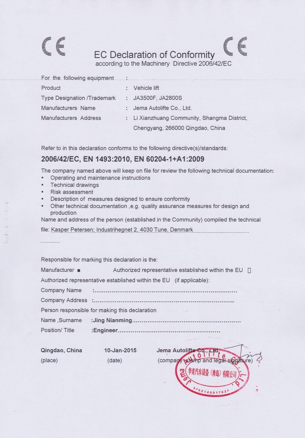
22 22
TW 250 B4.5 Clear Floor Two Post Lift Lifting Capacity 5000KG
 TW 250 B4.5 Clear Floor Two Post Lift Lifting Capacity 5000KG Installation, Operation and Parts Manual Please read this entire manual carefully and completely before installation or operation of the lift.
Index. 1. Important safety instructions Overview of the lift Installation instructions Operation instructions 8-9
 2 Index 1. Important safety instructions 4-5 1.1 Safety Warnings 1.2 Qualified personnel 1.3 Safety 1.4 Warning signs 2. Overview of the lift 6 2.1 General descriptions 2.2 Technical data 2.3 Construction
Model No. 42CE 2 POST LIFT
 Model No. 42CE 2 POST LIFT Clear Floor Two Post Lift, Electrical Release Lifting Capacity 3500KG/4200KG Installation, Operation and Parts Manual Distributed by Please read this entire manual carefully
Model No. EE-6215E. Installation, Operation and Parts Manual. Distributed by. Clear Floor Two Post Lift, Electrical Release Lifting Capacity 5000KG
 Model No. Clear Floor Two Post Lift, Electrical Release Lifting Capacity 5000KG Installation, Operation and Parts Manual Distributed by Please read this entire manual carefully and completely before installation
EE-6214EKZ INSTALLATION, OPERATION AND MAINTENANCE MANUAL
 EE-6214EKZ Asymmetry Clear Floor Two Post Lift Electrical Release Lifting Capacity: 4500 KG INSTALLATION, OPERATION AND MAINTENANCE MANUAL Read this entire manual carefully and completely before installation
S3 10 E. Installation Operation and Maintenance Manual. Scissor Lift Lifting Capacity: 3000 Kg
 S3 10 E Scissor Lift Lifting Capacity: 3000 Kg Installation Operation and Maintenance Manual Please read the entire manual before installation and operation 2 TWIN BUSCH GmbH INDEX 1. Important safety
Original JA3000S INSTALLATION, OPERATION AND MAINTENANCE MANUAL ORIGINAL INSTRUCTION WE ARE HERE TO SURPRISE. Service scissor Lift
 Lifting Capacity: 3000KG JA3000S Service scissor Lift INSTALLATION, OPERATION AND MAINTENANCE MANUAL ORIGINAL INSTRUCTION Original Read this entire manual carefully and completely before installation and
INSTALLATION, OPERATION AND MAINTENANCE MANUAL
 TW 242 PE B4.3 Two Post Lift Lifting Capacity: 4200 KG INSTALLATION, OPERATION AND MAINTENANCE MANUAL Read this entire manual carefully before installation or operation of the lift. Follow the instructions
MODEL NO: EE-6263C / 6264C INSTALLATION OPERATION AND PARTS MANUAL
 INSTALLATION OPERATION AND PARTS MANUAL Edition:A MODEL NO: EE-6263C / 6264C Clear Floor Two Post Lift Asymmetric style Electrical Release Lifting Capacity: 3200KG/4000KG Read this entire manual carefully
Installation, operation and maintenance manual
 Installation, operation and maintenance manual HCT1LX30 FULL RISE SCISSOR LIFT READ THIS ENTIRE MANUAL BEFORE INSTALLATION TO ENSURE CORRECT OPERATION AND A LONG SERVICE LIFE 2 Tiraines str. Riga, LV 1058
TW 250 B4.5 HEAVY-LINE 2-post lift
 TW 250 B4.5 HEAVY-LINE 2-post lift Floor free Lifting capacity: 5000 kg INSTALLATION, OPERATION AND MAINTENANCE MANUAL Read this entire manual carefully and completely before installation or operation
INSTALLATION, OPERATION AND MAINTENANCE MANUAL
 Installation, Operation and Parts Manual TW-236EB3.9 TW 236 PE B3.9 Clear Floor Two Post Lift INSTALLATION, OPERATION AND MAINTENANCE MANUAL Please read this entire manual carefully before installation
EE 6435S, 6435A, 6435B Electrical Release FOUR POST LIFT with PD
 EE 6435S, 6435A, 6435B Electrical Release FOUR POST LIFT with PD ATTENTION: READ THIS ENTIRE MANUAL BEFORE INSTALLATION TO ENSURE A CORRECT OPERATION AND LONG SERVICE LIFE. INSTALLATION/OWNERS MANUAL Read
Model SL-12K-A SCISSOR LIFT. wheel alignment model. (11000 LBS / 5000Kg Capacity) INSTALLATION & OPERATION INSTRUCTION (SECOND EDITION)
 INSTALLATION & OPERATION INSTRUCTION (SECOND EDITION)") Model SL-12K-A SCISSOR LIFT wheel alignment model (11000 LBS / 5000Kg Capacity) INSTALLATION & OPERATION INSTRUCTION (SECOND EDITION) 2007. 6. CONTENTS Chapter 1 Introduction & Specifications ---------------------------------------
Model SL-12K-A SCISSOR LIFT wheel alignment model (11000 LBS / 5000Kg Capacity) INSTALLATION & OPERATION INSTRUCTION (SECOND EDITION) 2007. 6. CONTENTS Chapter 1 Introduction & Specifications ---------------------------------------
CONTENTS. Product Features and Specifications Installation Requirement Installation Exploded View Operation Instruction...
 1 CONTENTS Product Features and Specifications... 3 Installation Requirement... 5 Installation... 6 Exploded View... 20 Test... 22 Operation Instruction... 25 Maintenance... 26 Trouble Shooting... 27 Parts
Read this entire manual before operation begins.
 Read this entire manual before operation begins. Record below the following information which is located on the serial number data plate. Serial No. Model No. Date of Installation Contents Specifications.............
ATTENTION. 1. Do not attempt to use the power unit to extend your cylinder. This must be done manually.
 NSS8XLT Installation Manual ATTENTION By following the instructions in this manual you can save yourself much time, frustration and money. The installation of your lift will take 4-5 hours. Do not rush.
Read this entire manual before operation begins.
 Read this entire manual before operation begins. Record below the following information which is located on the serial number data plate. Serial No. Model No. Date of Installation Contents Specifications.............
Read this entire manual before operation begins.
 Read this entire manual before operation begins. Record below the following information which is located on the serial number data plate. Serial No. Model No. Date of Installation Contents Specifications.............
Hydraulic Breakers HH35. Prior to Operation. From Serial No Revised We thank you for choosing a HYCON breaker.
 Hydraulic Breakers HH35 From Serial No. 12263 Revised 01.02.2015 Prior to Operation We thank you for choosing a HYCON breaker. To ensure smooth operation and long-lasting performance of your new breaker,
CONTENTS. Product Features and Specifications...1. Installation Requirement...3. Steps of Installation...4. Exploded View Test Run...
 TP10AS 2-POST LIFT CONTENTS Product Features and Specifications...1 Installation Requirement...3 Steps of Installation...4 Exploded View...24 Test Run....28 Operation Instruction...29 Maintenance...30
CONTENTS. Product Features and Specifications...1. Installation Requirement Steps of Installation.. 5. Exploded View Test Run...
 CONTENTS Product Features and Specifications...1 Installation Requirement... 4 Steps of Installation.. 5 Exploded View...21 Test Run...26 Operation Instruction...27 Maintenance... 28 Trouble Shooting...
30-SS1203A 12,000 LB CAPACITY SCISSOR ALIGNMENT LIFT INSTALLATION AND SERVICE MANUAL P/N:
 WITH STRENGTH 30-SS1203A 12,000 LB CAPACITY SCISSOR ALIGNMENT LIFT INSTALLATION AND SERVICE MANUAL P/N: 420-02553 CONTENTS Product Features and Specifications...1 Installation Requirement...3 Steps of
Read this entire manual before operation begins.
 Read this entire manual before operation begins. Record below the following information which is located on the serial number data plate. Serial No. Model No. Date of Installation Contents Specifications.............
CONTENTS. Product Features and Specifications Installation Requirement Steps of Installation 4. Exploded View Test Run...
 CONTENTS Product Features and Specifications... 1 Installation Requirement... 3 Steps of Installation 4 Exploded View... 14 Test Run... 16 Operation Instruction... 19 Maintenance... 20 Trouble Shooting...
HPD Hydraulic Post Driver
 HPD Hydraulic Post Driver From serial No. 7600 Revised 04.01.2013 Prior to Operation We thank you for choosing a HYCON Post Driver. To ensure smooth operation and long-lasting performance of your new post
4QJY4.0-C & 4QJY4.0-C1 four post parking lift. Manual
 4QJY4.0-C & 4QJY4.0-C1 four post parking lift Manual Contents 1 Safety instruction and attentions.. 3 1.1 Cautions with words......3 1.2 Safety caution signal 4 1.3 Using Purpose.. 5 1.4 Expected Rated
Service Jacks. Operating Instructions & Parts Manual. Model Number. Capacity 4 Ton 4 Ton Air/ Manual 10 Ton 10 Ton Air/ Manual HW93657/ HW93660
 Service Jacks Operating Instructions & Parts Manual Model Number HW93657 HW93667 HW93660 HW93662 Capacity 4 Ton 4 Ton Air/ Manual 10 Ton 10 Ton Air/ Manual Made in North America HW93657/ HW93660 HW93667/
2 Ton - 50 Ton Bottle Jack
 Please dispose of packaging for the product in a responsible manner. It is suitable for recycling. Help to protect the environment, take the packaging to the local amenity tip and place into the appropriate
HEAVY DUTY TROLLEY JACK. Operation Manual
 HEAVY DUTY TROLLEY JACK 4T Operation Manual Make sure to read and fully understand the instruction manual before using this product and keep the manual properly 1 General Description Product Description
Read this entire manual before operation begins.
 Rev. 12/12/2017 Read this entire manual before operation begins. Record below the following information which is located on the serial number data plate. Serial No. Model No. Date of Installation Contents
CONTENTS. Product Features and Specifications...1. Installation Requirement Steps of Installation.. 5. Exploded View Test Run...
 CONTENTS Product Features and Specifications...1 Installation Requirement... 3 Steps of Installation.. 5 Exploded View...18 Test Run...21 Operation Instruction...22 Maintenance... 23 Trouble Shooting...
3 Ton Trolley Jack. Please read and fully understand the instructions in this manual before operation. Keep this manual safe for future reference.
 Please dispose of packaging for the product in a responsible manner. It is suitable for recycling. Help to protect the environment, take the packaging to the local amenity tip and place into the appropriate
Installation/Operation/Service Manual
 TLX12/TLX12A Installation/Operation/Service Manual CONTENTS Product Features and Specifications...1 Installation Requirement...3 Steps of Installation...4 Exploded View...23 Test Run...28 Operation Instruction...29
Trolley jack K K K K K K 21242
 Trolley jack K 21240 K 21241 K 21242 K 21241 K 21240 K 21242 1 INSTRUCTIONS FOR USE IMPORTANT Read these instructions carefully and store this manual in a place where you can easily find it as you may
ASSEMBLY & OPERATION INSTRUCTION MANUAL
 Sliding Bridge Jack 3,500 lbs. Capacity ASSEMBLY & OPERATION INSTRUCTION MANUAL TABLE OF CONTENTS Specifications... 2 Description & Features... 3 Installation Instructions... 4 Safety Instructions... 4
Models PR-12F PR-12C PR-15C SURFACE MOUNTED TWO-POST LIFTS INSTALLATION AND OPERATION MANUAL
 Forward this manual to all operators. Failure to operate this equipment as directed may cause injury. INSTALLATION AND OPERATION MANUAL SURFACE MOUNTED TWO-POST LIFTS Models PR-12F PR-12C PR-15C Keep this
Atlas PV-9WP Addendum
 Atlas PV-9WP Addendum 9,000 lb. Capacity Two-Post Overhead Lift The Atlas PV-9WP above ground hoist is 6 inches wider than the Atlas PV-9P, giving it an overall width of 141 (11 9 ) and a drive thru width
Read this entire manual before operation begins.
 Read this entire manual before operation begins. Record below the following information which is located on the serial number data plate. Serial No. Model No. Date of Installation Contents Specifications.............
AU DU PONT DE LUTTRE BRUSSELS BELGIUM PHONE: FAX: OPERATING MANUAL. Electric Fully Automatic Floor Saw FS 1218 EX
 AU DU PONT DE LUTTRE 74-1190 BRUSSELS BELGIUM PHONE: 322 34 83 162 FAX: 322 34 83 136 OPERATING MANUAL Electric Fully Automatic Floor Saw FS 1218 EX 2 Important information before you start! When the machine
IMPORTANT INSTRUCTIONS FOR OPERATION & MAINTENANCE OF
 IMPORTANT INSTRUCTIONS FOR OPERATION & MAINTENANCE OF CONVEYORS EASIKIT 300 EASIKIT 450 EASIKIT 600, 900, 1200 & 1500 The manufacturer does not accept responsibility for any loss, damage to other equipment,
Installation Instructions X-Force UTV Lift (000 Series) Capacity 2,275 lbs (1,035 kg)
 Capacity 2,275 lbs (1,035 kg)") Installation Instructions X-Force UTV Lift (000 Series) Capacity 2,275 lbs (1,035 kg) Read entire manual before assembling, installing, operating, or servicing this equipment. LP20640 IN20793 September
Installation Instructions X-Force UTV Lift (000 Series) Capacity 2,275 lbs (1,035 kg) Read entire manual before assembling, installing, operating, or servicing this equipment. LP20640 IN20793 September
Model FP14KO-A Wheel alignment & Open Front Four-Post Lift
 Model FP14KO-A Wheel alignment & Open Front Four-Post Lift ( 14000LBS / 6300Kg Capacity) ASSEMBLY & OPERATION INSTRUCTIONS ( Series T1) 2009.7. INTRODUCTION Model FP14KO-A is a four-post lift is used in
Models: SURFACE MOUNTED FOUR-POST LIFTS INSTALLATION AND OPERATION MANUAL
 Forward this manual to all operators. Failure to operate this equipment as directed may cause injury. INSTALLATION AND OPERATION MANUAL SURFACE MOUNTED FOUR-POST LIFTS Models: FL-18 BP-18 BP-27/ BP-27A
HH10/HH10RV Hydraulic Breaker
 Prior to Operation HH10/HH10RV Hydraulic Breaker HH10 from serial No. 1451 HH10RV from serial No. 2741 Revised 30.08.2011 We thank you for choosing a HYCON breaker. To ensure smooth operation and long-lasting
VEHICLE POSITIONING JACK
 VEHICLE POSITIONING JACK Model No: VPJ300 PART NO: 7624100 OPERATING & MAINTENANCE INSTRUCTIONS GC06/12 INTRODUCTION Thank you for purchasing this CLARKE Vehicle Positioning Jack. Before attempting to
TWO POST LIFT. Operation Manual & Instruction STRONGMAN TOOLS LTD
 TWO POST LIFT USER S MANUAL Operation Manual & Instruction STRONGMAN TOOLS LTD 1 IMPORTANT SAFETY INSTRUCTIONS SAVE THESE INSTRUCTIONS PLEASE READ THE ENTIRE CONTENTS OF THIS MANUAL PRIOR TOINSTALLATION
Hand Pallet Truck NC. Operation Manual
 Hand Pallet Truck -------NC Operation Manual Operation Manual 1 Application Range This product is suitable for using in rated load of up to 5500lbs. This PL5500HD is the perfect jack for handling palletized
3.25 Ton Heavy Duty Floor Jack
 Please dispose of packaging for the product in a responsible manner. It is suitable for recycling. Help to protect the environment, take the packaging to the local amenity tip and place into the appropriate
HCS14/16/18 Hydraulic Cut-off Saw. Prior to Operation. We thank you for choosing a HYCON cut-off saw.
 Prior to Operation HCS14/16/18 Hydraulic Cut-off Saw From serial No. 0164 Revised September 2003 HYCON A/S Vester Hassingvej 33 DK-9320 Hjallerup Denmark Tel: +45 9647 5200 Fax: +45 9647 5201 Mail hycon@hycon.dk
HYDRAULIC PALLET TRUCK MODEL NO: PT540M/BM/CM & PT685BM/CM PART NO: , , , ,
 HYDRAULIC PALLET TRUCK MODEL NO: PT540M/BM/CM & PT685BM/CM PART NO: 7631700, 7631705, 7631710, 7631715, 7631720 OPERATION & MAINTENANCE INSTRUCTIONS LS0316 INTRODUCTION Thank you for purchasing this CLARKE
Before equipment use, please read this operation manual carefully. Serial Number: Date Purchased:
 Pushed & Geared Trolleys OPERATION MANUAL This operation manual is intended as an instruction manual for trained personnel who are in charge of installation, maintenance, repair etc. Before equipment use,
1100W PORTABLE GENERATOR
 1100W PORTABLE GENERATOR MODEL NO: G1200 PART NO: 8010110 OPERATION & MAINTENANCE INSTRUCTIONS LS0312 INTRODUCTION Thank you for purchasing this CLARKE 1100W Portable Generator. Before attempting to use
Installation Instructions
 Instructions Created by an: DIY Underhood LED Lighting Kit (SKU# DIY-E-UHLK) Installation Instructions NOTICE: This Under Hood Light Kit was installed on a 2002 Toyota Tacoma. However, these instructions
GLO-8000 SERIES (GLO-8000 & GLO-8000XLT)
") GLO-8000 SERIES (GLO-8000 & GLO-8000XLT) 8,000 LBS. CAPACITY FOUR-POST STORAGE LIFT INSTALLATION & OPERATION MANUAL SERIAL NUMBER: INSTALLATION DATE: EAGLE EQUIPMENT 1-800-336-2776 REV2011 03.0 BD SHIPPING
GLO-8000 SERIES (GLO-8000 & GLO-8000XLT) 8,000 LBS. CAPACITY FOUR-POST STORAGE LIFT INSTALLATION & OPERATION MANUAL SERIAL NUMBER: INSTALLATION DATE: EAGLE EQUIPMENT 1-800-336-2776 REV2011 03.0 BD SHIPPING
SIP Direct Drive Oil-Lube Air Compressors - Operating & Maintenance Instructions
 SIP Direct Drive Oil-Lube Air Compressors - Operating & Maintenance Instructions Please read and fully understand the instructions in this manual before operation. Keep this manual safe for future reference.
WESCO INDUSTRIAL PRODUCTS, INC. Scale Pallet Truck. Part Number: &
 WESCO INDUSTRIAL PRODUCTS, INC Scale Pallet Truck Part Number: 272936 & 272938 Note: Operator MUST read and understand these operating instructions before using this Hand Pallet Truck. Page 1 of 16 TABLE
Instruction Manual For Auto Shift Hydraulic Lift Table
 Instruction Manual For Auto Shift Hydraulic Lift Table Model Number: CART-550-AS Note: Owner/Operator must read and understand this Instruction Manual before operating the lift & tilt table. Contents 1
ELECTRIC PALLET TRUCK
 π H-3405 ELECTRIC PALLET TRUCK 1-800-295-5510 uline.com GENERAL SAFETY GUIDELINES WARNING! Do not operate this truck unless you have been trained to use it, authorized to do so and have checked it is in
USE AND MAINTENANCE MANUAL
 USE AND MAINTENANCE MANUAL TWO POST VEHICLE LIFT 2 IMPORTANT SAFETY INSTRUCTIONS SAVE THESE INSTRUCTIONS WARNING! PLEASE READ THE ENTIRE CONTENTS OF THIS MANUAL PRIOR TOINSTALLA- TION AND OPERATION. BY
HYDRAULIC PALLET TRUCK. MODEL No: PTE550 PART Nos OPERATION & MAINTENANCE INSTRUCTIONS
 HYDRAULIC PALLET TRUCK MODEL No: PTE550 PART Nos 7630171 OPERATION & MAINTENANCE INSTRUCTIONS 0604 Please read these instructions carefully before operating the truck Thank you for purchasing this CLARKE
20 TONNE HYDRAULIC PRESS MODEL NO: CSA20FBT
 20 TONNE HYDRAULIC PRESS MODEL NO: CSA20FBT PART NO: 7614058 OPERATION & MAINTENANCE INSTRUCTIONS WARNING: Read these instructions before using the press GC0516 INTRODUCTION Thank you for purchasing this
1700 Pup Wagon. Owner s Manual
 1700 Pup Wagon Owner s Manual General Information 1 Introduction This chapter will provide you with important information regarding the safe operation of your unit as well as necessary warranty information.
ASSEMBLY & OPERATION INSTRUCTION MANUAL
 LR-26-PAD 6000 lb Capacity Low-Rise Pad Lift ASSEMBLY & OPERATION INSTRUCTION MANUAL 6,000 LB. LOW-RISE PAD LIFT Easy frame lifting on padded runways. Great for wheel and brake work, tire and wheel changing
1500 Series Roll Off Hoist. Owner s Manual (5-06)
") 1500 Series Roll Off Hoist Owner s Manual (5-06) Section 1: General Information Introduction Safety Information Warranty Information Table of Contents Section 2: Operation Operating the P.T.O. Operating
1500 Series Roll Off Hoist Owner s Manual (5-06) Section 1: General Information Introduction Safety Information Warranty Information Table of Contents Section 2: Operation Operating the P.T.O. Operating
Sectional and Tilting Door Opener
 Sectional and Tilting Door Opener Installation Instructions and User Guide 600 800 1000 S/N WARNING Please read the manual carefully before installation and use. The installation of your new door opener
PNL-MS Belt Conveyor with Metal Detector
 PNL-MS Belt Conveyor with Metal Detector Date: Apr, 2013 Version: Ver.B (English) Contents 1. General Description... 7 1.1 Coding Principle... 8 1.2 Features:... 8 1.2.1 Specifications Table... 10 1.2.2
Operating Instructions
 Operating Instructions Parts List Hand Pallet Truck Note: Operator MUST read and understand this operating instructions before use this Hand Pallet Truck. Thank you for using our pallet truck. Your pallet
MODEL EGA200 OWNERS MANUAL
 3/8 RATCHET WRENCH MODEL EGA200 OWNERS MANUAL www.eaglecompressor.com 1-800-551-2406 READ THE ENTIRE MANUAL BEFORE PUTTING THIS TOOL IN SERVICE Limited Air Tool Warranty Wood Industries, Inc. warrants
Read this entire manual before operation begins.
 Read this entire manual before operation begins. Record below the following information which is located on the serial number data plate. Serial No. Model No. Date of Installation Contents Specifications.............
OPERATION & MAINTENANCE INSTRUCTIONS
 10 TONNE HEAVY DUTY LONG CHASSIS TROLLEY JACK MODEL NO: CTJ10GLS PART NO: 7623095 OPERATION & MAINTENANCE INSTRUCTIONS LS0915 INTRODUCTION Thank you for purchasing this CLARKE 10 Tonne Heavy Duty Long
50 TONNE HYDRAULIC PRESS MODEL NO: CSA50FP
 50 TONNE HYDRAULIC PRESS MODEL NO: CSA50FP PART NO: 7615202 OPERATION & MAINTENANCE INSTRUCTIONS WARNING: Read these instructions before using the press GC0516 INTRODUCTION Thank you for purchasing this
Hand Pallet Truck 2.5 tons
 For your safety Please read this instruction manual before you use the Hand Pallet Truck! Contents: Part List and Instruction Model.: XTN 540-1150 Please keep these instructions for future reference. Hand
MODEL EGA130 OWNERS MANUAL
 3/4 IMPACT WRENCH MODEL EGA130 OWNERS MANUAL www.eaglecompressor.com 1-800-551-2406 READ THE ENTIRE MANUAL BEFORE PUTTING THIS TOOL IN SERVICE Limited Air Tool Warranty Wood Industries, Inc. warrants air
Instruction Manual. Hydraulic Jack. Note: The Owner/Operator must read carefully and understand all the information presented here before operation.
 Instruction Manual Hydraulic Jack Note: The Owner/Operator must read carefully and understand all the information presented here before operation. 0 Contents 1 Warning in advance 2 2 Description.. 2 3
OPERATIONS MANUAL LEVER CHAIN HOIST
 OPERATIONS MANUAL LEVER CHAIN HOIST IMPORTANT SAFETY INFORMATION Please read, understand and follow all safety information contained in these instructions prior to the use of this hoist. Retain these instructions
Lifting height 5.5" - 72" with adapters " Height overall 165" Width between columns 122" Drive through 109" Width overall 151.
 Model Number TP12KC-D Capacity 12,000 lbs. Lifting height 5.5" - 72" with adapters 79.625" Height overall 165" Width between columns 122" Drive through 109" Width overall 151.125" Arm extension 37.5" -
9,000 POUND TWO-COLUMN AUTOMOTIVE LIFT Model: NW-2-9KFP MANUAL
 9,000 POUND TWO-COLUMN AUTOMOTIVE LIFT Model: NW-2-9KFP MANUAL 1 9,000 POUND CAPACITY MODEL: NW-2-9KFP TWO-COLUMN AUTOMOTIVE LIFT READ THIS ENTIRE MANUAL BEFORE OPERATION BEGINS RECORD BELOW THE FOLLOWING
Heavy Duty Engine Cranes
 Heavy Duty Engine Cranes Operating Instructions & Parts Manual Model Number Atd-7484 Atd-7485 (Foldable Legs) Capacity 2 Ton 2 Ton Model Atd-7484 Model Atd-7485 Atd Tools Inc. 160 Enterprise Drive, Wentzville,
SCISSOR LIFT Model MR6K-38 /161108A 6,000lb Capacity Operation Manual
 SCISSOR LIFT Model MR6K-38 /161108A 6,000lb Capacity Operation Manual (Version A) 2009. Apr. CONTENT 1. Safety Note, Caution and Warning Important Information Safety Instructions 2. Technical Manual Product
HYDRAULIC PALLET TRUCKS
 HYDRAULIC PALLET TRUCKS HYDRAULIC PALLET TRUCKS MODEL Nos: PT550 GAL & PT685 GAL PART Nos: 7630234 & 7630236 OPERATION & MAINTENANCE INSTRUCTIONS 0204 Please read these instructions carefully before operating
Power of motor (KW) Power supply(v) Please note that if you use 220V power supply, you need to have a manostat.
 Power supply(v) Please note that if you use 220V power supply, you need to have a manostat.") Ⅰ. Introduction 1. Abstract The double-cylinder hydraulic lift is a hydraulic drive vehicle lift equipment developed by our company. It is designed briefly and reasonable. It select hydraulic power unit,
Ⅰ. Introduction 1. Abstract The double-cylinder hydraulic lift is a hydraulic drive vehicle lift equipment developed by our company. It is designed briefly and reasonable. It select hydraulic power unit,
THE ERGO-MATIC DRUM TRANSPORT POWER DRIVE SERIES MODEL PWPL 750 OWNERS MANUAL
 THE ERGO-MATIC DRUM TRANSPORT POWER DRIVE SERIES MODEL PWPL 750 OWNERS MANUAL WARNING: Do not install, operate or service this product unless you have read and understand the safety practices, warnings,
Vertical Stacking System for both Floor and Roof Lines. SQ-1 INTELLIGENT STACKERS. Operators Manual
 Vertical Stacking System for both Floor and Roof Lines. SQ-1 INTELLIGENT STACKERS Operators Manual FOREWORD This manual explains the proper maintenance of Square 1 Design Intelligent Stacking System as
MODEL EGA220 OWNERS MANUAL
 1/4 MINI RATCHET MODEL EGA220 OWNERS MANUAL www.eaglecompressor.com 1-800-551-2406 READ THE ENTIRE MANUAL BEFORE PUTTING THIS TOOL IN SERVICE Limited Air Tool Warranty Wood Industries, Inc. warrants air
Quick Install Lift AL065 Installation Guide & Owners Manual
 Quick Install Lift AL065 Installation Guide & Owners Manual Congratulations on your new lift purchase. The Quick Install Lift line is one of the easiest and most trouble free ways to transport your scooter
Sectional and Tilting Door Opener Installation Instructions and User Guide
 Sectional and Tilting Door Opener Installation Instructions and User Guide ET-600E ET-800E ET-1000E S/N WARNING Please read the manual carefully before installation and use. The installation of your new
Floor Plate Style Lift And Overhead Beam Style Lift. Two Post Lift
 Floor Plate Style Lift And Overhead Beam Style Lift 9,000 POUND Two Post Lift ASSEMBLY & OPERATION INSTRUCTION TABLE OF CONTENTS Important Note Page 3 Definition Page 4 Preparation and General Information
I. General Safety Precautions
 1 2 ATV/UTV WINCH Thank you for purchasing a. This manual covers operation and maintenance of the winch. All information in this publication is based on the latest production information available at the
Heavy Duty Engine Cranes
 Heavy Duty Engine Cranes Operating Instructions & Parts Manual Model Number ATD-7484 ATD-7485 (Foldable Legs) Capacity 2 Ton 2 Ton Model ATD-7484 Model ATD-7485 WARNING: This product may contain chemicals,
1200W INVERTER GENERATOR
 1200W INVERTER GENERATOR MODEL NO: IG1200 PART NO: 8877070 OPERATION & MAINTENANCE INSTRUCTIONS LS0117 INTRODUCTION Thank you for purchasing this CLARKE 1200W Inverter Generator. Before attempting to use
STUDIO - TRAINING MANUAL
 STUDIO - TRAINING MANUAL SIMPLE TANNING SYSTEMS built purposely for a perfect spray tan. WELCOME Thank you for choosing the Tanning Essentials Studio Spray Tan System. Please read the following to help
OPERATOR S MANUAL FOR PICK UP LIFT
 ALUHEBETECHNIK Gesellschaft mbh Office: Factory: Hauptplatz 23 Bahnstraße 34 A-2474 Gattendorf Tel. (43) 2142 64260 (43) 2142 64360 E-Mail: Fax. (43) 2142 6434 (43) 2142 64366 office@aht-mhw.com OPERATOR
SELF PRIMING CHEMICAL SERVICE PUMPS
 SELF PRIMING CHEMICAL SERVICE PUMPS INSTALLATION AND OPERATING INSTRUCTIONS This Manual covers: SELF PRIMING MODEL RANGE J50ECX TO J250ECX STAINLESS STEEL*, and NON METALLIC SEAL PUMP MODEL: SERIAL NO:
1. GENERAL SPECIFICATIONS 2. TO ATTACH DRAW-BAR TO PUMP UNIT
 Thank you for using our pallet truck. Your pallet truck is made of high quality steel and is designed for the horizontal lifting and transport of loads on a pallet or standardized containers on a level,
BFQ Hand Pallet Truck -Quick Lift Operation Manual
 BFQ Hand Pallet Truck -Quick Lift Operation Manual Original instruction Ningbo Ruyi Joint Stock Co.,Ltd 656 North Taoyuan Road, Ninghai 315600,Zhejiang,P.R. China EC Declaration of Conformity According
Parallel Lift Rack MODEL RM
 Form 4401T, 09-03 Supersedes Form 4401T, 10-00 OPERATION INSTRUCTIONS Parallel Lift Rack MODEL RM Copyright 1998-2003 Hunter Engineering Company Contents 1. For Your Safety... 1 1.1 Warning/Instruction
ASSEMBLY & OPERATION MANUAL. CDVK2 Power Tower RECORD SERIAL NUMBER HERE
 ASSEMBLY & OPERATION MANUAL CDVK2 Power Tower RECORD SERIAL NUMBER HERE www.inspirefitness.net by Health In Motion LLC Feb. 2011 TABLE OF CONTENTS Section Description.. Page Instructions.. 1 Tools Required
INSTALLATION MANUAL & OPERATION INSTRUCTIONS. OVERHEAD CAR LIFT 2-POST LIFT AUTO HOIST APlusLift HW-10KOH
 INSTALLATION MANUAL & OPERATION INSTRUCTIONS OVERHEAD CAR LIFT 2-POST LIFT AUTO HOIST APlusLift HW-10KOH 1 READ THIS MANUAL COMPLETELY BEFORE INSTALLING LIFT!!! DISTRIBUTED BY: Songa Enterprises LLC 8512
CRD610 Automatic Fitting Inserter
 CRD610 Automatic Fitting Inserter OPERATIONS MANUAL VERSION 1.2 LAST EDITED 12.12.2018 cleanroomdevices.com 1 Table of Contents Title Page. 1 Table of Contents...2 1.0 General Product & Safety Information....3