18673, INSTALLATION INSTRUCTIONS
|
|
|
- Dwain Oscar Lyons
- 5 years ago
- Views:
Transcription
1
2

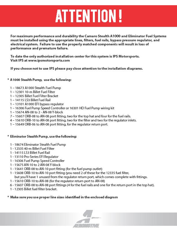
3 18673, INSTALLATION INSTRUCTIONS WARNING! The fuel system is under pressure. Do not open the fuel system until the pressure has been relieved. Refer to the appropriate vehicle service manual for the procedure and precautions for relieving the fuel system pressure. This pump assembly is a high performance factory replacement unit. Key features: Drops directly into the factory fuel tank (NO CUTTING REQUIRED). Utilizes the factory jet siphon system so it operates just like GM intended. High flow pre-filter built into inlet of pump. Includes fuel level mounting bracket for factory leveling unit. NOTE: The use of Teflon braided line with machine crimped hose ends is recommended. This eliminates the possibility of fuel vapors permeating through the fuel line. The use of a speed pump controller is also highly recommended, this will keep the fuel cool and reduce noise inside the passenger compartment. CAUTION: Installation of this product requires detailed knowledge of automotive systems and repair procedures. We recommend that this installation be carried out by a qualified automotive technician. Installation of this product requires handling of gasoline. Ensure you are working in a well ventilated area with an approved fire extinguisher nearby. Extinguish all open flames, prohibit smoking and eliminate all sources of ignition in the area of the vehicle before proceeding with the installation. Maximum continuous operating pressure should not exceed 70 psi. The enclosed Aeromotive fuel pump utilizes AN-08 ORB (O-ring Boss Ports) style outlet port and AN-08 return port; these ports are NOT PIPE THREAD and utilize NO THREAD SEALANT. NOTICE TO INSTALLER: Installation of this fuel pump requires fuel system conversion to a return style fuel system (use of a bypass style regulator). Also note that a check engine light may be present after installation due to the factory returnless system being modified. This can be turned off with tuning software. NOTE: Due to tight clearance between the top of the fuel tank and body, Aeromotive includes fuel tank strap spacers and high density foam to space the tank down. Compatible Fuels: Pump Gas Race Gas E85 Alcohol/Ethanol
 13101 (10AN ports) 13109 (6AN ports) Fuel Rails: 14106 (LS1/LS6) Electrical Components: 14114 (LS2) 16301 (pump wiring kit) 14115 (LS3/L76) 16306 (pump speed")

4 Aeromotive Related LS Components: Fuel Filters: Check Valves: (pump/race gas) 10 micron (6AN) (race gas/e85) 40 micron (10AN) (filter bracket) Fuel Pressure Gauge: Fuel Pressure Regulators: (dry 0-100psi) (10AN ports) (6AN ports) Fuel Rails: (LS1/LS6) Electrical Components: (LS2) (pump wiring kit) (LS3/L76) (pump speed controller) (LS7) (LS1, Edelbrock 29085) (Platinum LS1/LS6) TOP PLATE LAYOUT The following steps are typical of most installations: 1. Disconnect the negative battery cable and drain the fuel tank. 2. Raise and support the vehicle. 3. Remove the exhaust and rear wheels from vehicle. 4. Remove driveshaft heat shield, drive shaft and fuel tank heat shield. 5. Remove the emergency brake cables from the three way tee and swing them towards the rear of the vehicle. 6. Remove the lower shock bolts. 7. Disconnect rear sub frame wiring located on passenger side frame rail. 8. Disconnect all the following connections in Figure 1-1.


, tank straps and drop the tank out of the car.")
5 FIGURE Support the rearend (complete IRS sub frame) with a suitable jack (transmission jack works best). Remove the four 24mm bolts that hold the sub frame in. Carefully lower the rear end, paying close attention to the brake lines on each side of the frame. There is enough length on the brake lines to get the tank out without removing the calipers. Once lowered, support the complete IRS sub frame with jackstands. 10. Remove the evap canister. This is done by unplugging all hoses and wires and removing the two 10mm bolts. 11. Unplug and remove the wiring harness connection at the tank on the passenger side. 12. Remove the fuel tank strap mounting bolts (15mm), tank straps and drop the tank out of the car. NOTE: It s recommended to do this with two people. 13. Now remove the pressure feed line and pressure sensor. Also remove the lock ring holding the fuel pump module in place. NOTE: The fuel pump module is spring loaded and will pop up. FIGURE 1-2 FIGURE 1-2


6 12. Carefully remove the fuel pump assembly as not to bend the float arm. There will also be a fuel transfer tube located on the bottom side of the assembly. Release this connection and let it fall back into the tank. The figure below gives you a visual on the internal working of your fuel tank. FIGURE 1-3 FIGURE With the fuel pump assembly removed from the tank, remove the fuel level sensor. FIGURE 1-4 FIGURE 1-4


7 14. Now take Aeromotive fuel pump assembly and slide the leveling unit into it as illustrated in FIGURE 1-5. NOTE: When twisting the bottom tabs inward, be sure not to twist them into the wires on the bottom of the leveling unit. Move the leveling arm through it s full range of motion to ensure it clears the bracket tabs. FIGURE Cut the two wire connector off of the fuel level sensor and crimp them onto the two wires provide on the pump. NOTE: The sensor is a resistance output only, wiring polarity is bi-directional. 16. Make sure to place the factory o-ring in the receiver groove on the tank Figure 1-6. Failure to do so will result in fuel leakage and require removal of the tank again. FIGURE 1-6


8 17. Now the fuel pump is ready to install in the tank. The siphon connection has to be made as the fuel pump is being lowered into the fuel tank. FIGURE 1-7. NOTE: Bend the flex hose with the orange check valve on the Aeromotive pump assembly, so it points toward the float level. FIGURE Use the positioning marks on the pump to align the unit. FIGURE 1-8. Replace the lock ring on the top of the fuel pump assembly and rotate it to the locked position. If re-using the factory feed line, attach it to the Aeromotive pump at this time. NOTE: You must install a by-pass style regulator with return line in order for the fuel pump to function correctly. Failure to do so will result in poor performance and fuel pump/system failure. FIGURE 1-8


9 19. Affix the supplied foam strip to the top of the tank as shown in FIGURE 1-9. FIGURE Cut or splice the factory fuel level wires and attach them to the fuel level studs. Make sure you use stranded, insulated copper wire, with matching crimp-type connectors for all connections. Use the supplied rubber terminal boots to protect the terminals from the elements. NOTE: Position the fuel tank under the vehicle and allow yourself enough room to make the wire connections. 21. Since the factory GM fuel pump is pulse modulated you can not use the factory fuel pump wires to trigger the relay. Find a suitable 12V key on ignition source for the #85 connection on the relay. Hooking the factory wiring directly up the Aeromotive unit could result in wiring damage or pump failure.


10 22. Now the fuel tank is ready to be installed in the vehicle. Attach the return line to the Aeromotive top plate before installing the tank (15605 for the and for the 18674). Coil the return line up to keep it out of your way. Take the supplied fuel tank spacers and place them between the tank straps and body. See FIGURE Now reverse steps 12-1 to finish up the tank installation. FIGURE Route the return line under the vehicle noting to keep it away from heat and moving suspension components. 25. Find a suitable place in the engine bay to mount a return style regulator. Plumb the regulator per the manufactures installation instructions. 26. Key on to check for leaks and to set fuel pressure. If any leaks are found, immediately discontinue use of vehicle and repair the leak(s)! This finishes up the installation of your new Aeromotive Stealth fuel pump. AEROMOTIVE, INC Barton Street, Lenexa, KS fax
11 AEROMOTIVE, INC. LIMITED WARRANTY This Aeromotive Product, with proof of purchase dated on or after January 1, 2003, is warranted to be free from defects in materials and workmanship for a period of one year from the original date of purchase. No warranty claim will be valid without authentic, dated proof of purchase. This warranty is to the original retail purchaser and none other and is available directly from Aeromotive and not through any point of distribution or purchase. If a defect is suspected, the retail purchaser must contact Aeromotive directly to discuss the problem, possible solutions and obtain a Return Goods Authorization (RGA), if deemed necessary by the company. Please call and dial option 3 for the technical service dept. All returns must be shipped freight pre-paid to the company and with valid RGA before they will be processed. Aeromotive will examine any product returned with the proper authorization to determine if the failure resulted from a defect or from abuse, improper installation, misapplication or alteration. Aeromotive will then, at it s sole discretion, return, repair or replace the product. If any Aeromotive product is determined defective, buyer s exclusive remedy is limited in value to the sale price of the good. In no event shall Aeromotive be liable for incidental or consequential damages. Aeromotive expressly retains the right to make changes and improvements in any product it manufactures and sells at any time. These changes and improvements may be made without notice at any time and without any obligation to change the catalogs or printed materials. Aeromotive expressly retains the right to discontinue at any time and without notice any Aeromotive product that it manufactures or sells. This warranty is limited and expressly limits any implied warranty to one year from the date of the original retail purchase on all Aeromotive products. No person, party or corporate entity other than Aeromotive shall have the right to: determine whether or not this Limited Warranty is applicable to any Aeromotive product, authorize any action whatsoever under the terms and conditions of this Limited Warranty, assume any obligation or liability of any nature whatsoever on behalf of Aeromotive under the terms and conditions of this Limited Warranty. This Limited Warranty covers only the product itself and not the cost of installation or removal. This Limited Warranty is in lieu of and expressly excludes any and all other warranties, expressed or implied. This Limited Warranty gives you specific legal rights, and you may also have other rights which vary from state to state. Aeromotive, Inc Barton Street, Lenexa, KS Phone: (913) Fax: (913)
18642, INSTALLATION INSTRUCTIONS
 18642, 18643 INSTALLATION INSTRUCTIONS WARNING! The fuel system is under pressure. Do not open the fuel system until the pressure has been relieved. Refer to the appropriate vehicle service manual for
18670, INSTALLATION INSTRUCTIONS
 18670, 19871 INSTALLATION INSTRUCTIONS WARNING! The fuel system is under pressure. Do not open the fuel system until the pressure has been relieved. Refer to the appropriate vehicle service manual for
18660, 18661, & Stealth Fuel Cell INSTALLATION INSTRUCTIONS
 18660, 18661, 18662 & 18663 Stealth Fuel Cell INSTALLATION INSTRUCTIONS WARNING! The fuel system is under pressure. Do not open the fuel system until the pressure has been relieved. Refer to the appropriate
18318 INSTALLATION INSTRUCTIONS CHEVROLET IMPALA
 18318 INSTALLATION INSTRUCTIONS 65-66 CHEVROLET IMPALA The enclosed Aeromotive fuel tank/pump assembly utilizes an o-ring sealed AN-06 style feed, return and vent ports. These ports seal with o-rings;
AEROMOTIVE Part # & Mustang Stealth Fuel Tank w/fuel pump INSTALLATION INSTRUCTIONS
 AEROMOTIVE Part # 18685 &18686 86-98.5 Mustang Stealth Fuel Tank w/fuel pump INSTALLATION INSTRUCTIONS CAUTION: Installation of this product requires detailed knowledge of automotive systems and repair
18324 INSTALLATION INSTRUCTIONS 65 PONTIAC LEMANS
 18324 INSTALLATION INSTRUCTIONS 65 PONTIAC LEMANS The enclosed Aeromotive fuel tank/pump assembly utilizes an o-ring sealed AN-06 style feed, return and vent ports. These ports seal with o-rings; they
AEROMOTIVE Part # Fuel System Prime Kit INSTALLATION INSTRUCTIONS
 AEROMOTIVE Part # 17301 Fuel System Prime Kit INSTALLATION INSTRUCTIONS CAUTION: Installation of this product requires detailed knowledge of automotive systems and repair procedures. We recommend that
AEROMOTIVE Part # Generic EFI Fuel System INSTALLATION INSTRUCTIONS
 AEROMOTIVE Part # 17150 Generic EFI Fuel System INSTALLATION INSTRUCTIONS CAUTION: Installation of this product requires detailed knowledge of automotive systems and repair procedures. We recommend that
AEROMOTIVE Part # L 4V Fuel Rails INSTALLATION INSTRUCTIONS
 AEROMOTIVE Part # 14130 5.0L 4V Fuel Rails INSTALLATION INSTRUCTIONS CAUTION: Installation of this product requires detailed knowledge of automotive systems and repair procedures. We recommend that this
11202 INSTALLATION INSTRUCTIONS
 11202 INSTALLATION INSTRUCTIONS WARNING! The fuel system may be under pressure. Do not open the fuel system until any pressure has been relieved. The enclosed Aeromotive fuel pump utilizes an o-ring sealed
AEROMOTIVE Part # Generic Fuel System Kit INSTALLATION INSTRUCTIONS
 AEROMOTIVE Part # 17126 Generic Fuel System Kit INSTALLATION INSTRUCTIONS CAUTION: Installation of this product requires detailed knowledge of automotive systems and repair procedures. We recommend that
AEROMOTIVE Part # A3000 Regulator Assembly INSTALLATION INSTRUCTIONS
 AEROMOTIVE Part # 11217 A3000 Regulator Assembly INSTALLATION INSTRUCTIONS CAUTION: Installation of this product requires detailed knowledge of automotive systems and repair procedures. We recommend that
13101 / / and Installation Instructions
 13101 / 13151-13109 / 13159 and 13114 Installation Instructions WARNING! The fuel system is under pressure. Do not open the fuel system until the pressure has been relieved. Refer to the appropriate vehicle
AEROMOTIVE Part # Generic Fuel System Kit INSTALLATION INSTRUCTIONS
 AEROMOTIVE Part # 17242 Generic Fuel System Kit INSTALLATION INSTRUCTIONS CAUTION: Installation of this product requires detailed knowledge of automotive systems and repair procedures. We recommend that
AEROMOTIVE Part # & Generic Fuel System Kit INSTALLATION INSTRUCTIONS
 AEROMOTIVE Part # 17135 & 17136 Generic Fuel System Kit INSTALLATION INSTRUCTIONS CAUTION: Installation of this product requires detailed knowledge of automotive systems and repair procedures. We recommend
AEROMOTIVE Part # Generic Fuel System Kit INSTALLATION INSTRUCTIONS
 AEROMOTIVE Part # 17125 Generic Fuel System Kit INSTALLATION INSTRUCTIONS CAUTION: Installation of this product requires detailed knowledge of automotive systems and repair procedures. We recommend that
AEROMOTIVE Part # Subaru STI Fuel Rails INSTALLATION INSTRUCTIONS
 AEROMOTIVE Part # 14136 04-06 Subaru STI Fuel Rails INSTALLATION INSTRUCTIONS CAUTION: Installation of this product requires detailed knowledge of automotive systems and repair procedures. We recommend
AEROMOTIVE Part # A2000 Fuel Pump Kit INSTALLATION INSTRUCTIONS
 AEROMOTIVE Part # 17202 A2000 Fuel Pump Kit INSTALLATION INSTRUCTIONS CAUTION: Installation of this product requires detailed knowledge of automotive systems and repair procedures. We recommend that this
AEROMOTIVE Part # Ford 5.4L Shelby GT500 Mustang INSTALLATION INSTRUCTIONS
 AEROMOTIVE Part # 14144 07 Ford 5.4L Shelby GT500 Mustang INSTALLATION INSTRUCTIONS CAUTION: Installation of this product requires detailed knowledge of automotive systems and repair procedures. We recommend
AEROMOTIVE Part # Street Rod Fuel Pump System INSTALLATION INSTRUCTIONS
 AEROMOTIVE Part # 17201 Street Rod Fuel Pump System INSTALLATION INSTRUCTIONS CAUTION: Installation of this product requires detailed knowledge of automotive systems and repair procedures. We recommend
AEROMOTIVE Part # GM LS1 Fuel Rails INSTALLATION INSTRUCTIONS
 AEROMOTIVE Part # 14106 GM LS1 Fuel Rails INSTALLATION INSTRUCTIONS CAUTION: Installation of this product requires detailed knowledge of automotive systems and repair procedures. We recommend that this
AEROMOTIVE Part # C5 Corvette Fuel Rail Kit INSTALLATION INSTRUCTIONS
 AEROMOTIVE Part # 14128 99-04 C5 Corvette Fuel Rail Kit INSTALLATION INSTRUCTIONS CAUTION: Installation of this product requires detailed knowledge of automotive systems and repair procedures. We recommend
AEROMOTIVE Part # Subaru Fuel Rails for Top Feed Injectors WRX & STI INSTALLATION INSTRUCTIONS
 AEROMOTIVE Part # 14134 Subaru Fuel Rails for Top Feed Injectors 02-14 WRX & 07-14 STI INSTALLATION INSTRUCTIONS CAUTION: Installation of this product requires detailed knowledge of automotive systems
AEROMOTIVE Part # & Mustang 5.0L Stealth Fuel System Kit INSTALLATION INSTRUCTIONS
 AEROMOTIVE Part # 18653 & 18654 86-93 Mustang 5.0L Stealth Fuel System Kit INSTALLATION INSTRUCTIONS CAUTION: Installation of this product requires detailed knowledge of automotive systems and repair procedures.
AEROMOTIVE Part # and F-Body Fuel System Kit INSTALLATION INSTRUCTIONS
 AEROMOTIVE Part # 17101 and 17102 93-97 F-Body Fuel System Kit INSTALLATION INSTRUCTIONS CAUTION: Installation of this product requires detailed knowledge of automotive systems and repair procedures. We
AEROMOTIVE Part # INSTALLATION INSTRUCTIONS
 AEROMOTIVE Part # 16303 INSTALLATION INSTRUCTIONS CAUTION: Installation of this product requires detailed knowledge of automotive systems and repair procedures. We recommend that this installation be carried
AEROMOTIVE Part # Ford 5.0 Liter INSTALLATION INSTRUCTIONS
 AEROMOTIVE Part # 14101 86-98 Ford 5.0 Liter INSTALLATION INSTRUCTIONS CAUTION: Installation of this product requires detailed knowledge of automotive systems and repair procedures. We recommend that this
AEROMOTIVE Volkswagen 1.8T Fuel Rail Part # INSTALLATION INSTRUCTIONS
 AEROMOTIVE Volkswagen 1.8T Fuel Rail Part # 14163 INSTALLATION INSTRUCTIONS CAUTION: Installation of this product requires detailed knowledge of automotive systems and repair procedures. We recommend that
AEROMOTIVE Part # CHEVY/GMC Duramax Fuel System Kit RETRO FIT KIT FOR ½ LINES INSTALLATION INSTRUCTIONS
 AEROMOTIVE Part # 11803 01-10 CHEVY/GMC Duramax Fuel System Kit RETRO FIT KIT FOR ½ LINES INSTALLATION INSTRUCTIONS CAUTION: Installation of this product requires detailed knowledge of automotive systems
AEROMOTIVE Part # /2 4.6L SOHC Ford Fuel Rail Kit INSTALLATION INSTRUCTIONS
 AEROMOTIVE Part # 14125 96-98 1/2 4.6L SOHC Ford Fuel Rail Kit INSTALLATION INSTRUCTIONS CAUTION: Installation of this product requires detailed knowledge of automotive systems and repair procedures. We
AEROMOTIVE Part # Mustang 5.0L Fuel System Kit INSTALLATION INSTRUCTIONS
 AEROMOTIVE Part # 17103 83-93 Mustang 5.0L Fuel System Kit INSTALLATION INSTRUCTIONS CAUTION: Installation of this product requires detailed knowledge of automotive systems and repair procedures. We recommend
AEROMOTIVE Part # C5 Corvette Fuel Rail / Regulator Kit INSTALLATION INSTRUCTIONS
 AEROMOTIVE Part # 14129 99-04 C5 Corvette Fuel Rail / Regulator Kit INSTALLATION INSTRUCTIONS CAUTION: Installation of this product requires detailed knowledge of automotive systems and repair procedures.
AEROMOTIVE Part # Subaru STI Fuel Rail Kit INSTALLATION INSTRUCTIONS
 AEROMOTIVE Part # 14137 04-06 Subaru STI Fuel Rail Kit INSTALLATION INSTRUCTIONS CAUTION: Installation of this product requires detailed knowledge of automotive systems and repair procedures. We recommend
AEROMOTIVE Part # L Ford F L Ford Expedition L Ford F-250 Super Duty INSTALLATION INSTRUCTIONS
 AEROMOTIVE Part # 14118 97-03 5.4L Ford F-150 97-02 5.4L Ford Expedition 98-03 5.4L Ford F-250 Super Duty INSTALLATION INSTRUCTIONS CAUTION: Installation of this product requires detailed knowledge of
AEROMOTIVE Part # Ford 5.4L GT500 Shelby Mustang Fuel Rail Kit INSTALLATION INSTRUCTIONS
 AEROMOTIVE Part # 14145 07 Ford 5.4L GT500 Shelby Mustang Fuel Rail Kit INSTALLATION INSTRUCTIONS CAUTION: Installation of this product requires detailed knowledge of automotive systems and repair procedures.
AEROMOTIVE Part # L Ford F L Ford Expedition L Ford F-250 Super Duty INSTALLATION INSTRUCTIONS
 AEROMOTIVE Part # 14118 97-03 5.4L Ford F-150 97-02 5.4L Ford Expedition 98-03 5.4L Ford F-250 Super Duty INSTALLATION INSTRUCTIONS CAUTION: Installation of this product requires detailed knowledge of
AEROMOTIVE Part # / L SOHC Ford Fuel Rail Kit INSTALLATION INSTRUCTIONS
 AEROMOTIVE Part # 14119 98 1/2-04 4.6L SOHC Ford Fuel Rail Kit INSTALLATION INSTRUCTIONS CAUTION: Installation of this product requires detailed knowledge of automotive systems and repair procedures. We
AEROMOTIVE Part # Subaru Fuel Rails for Top Feed Injectors WRX & STI INSTALLATION INSTRUCTIONS
 AEROMOTIVE Part # 14135 Subaru Fuel Rails for Top Feed Injectors 02-14 WRX & 07-14 STI INSTALLATION INSTRUCTIONS CAUTION: Installation of this product requires detailed knowledge of automotive systems
AEROMOTIVE Part # INSTALLATION INSTRUCTIONS
 AEROMOTIVE Part # 14102 INSTALLATION INSTRUCTIONS CAUTION: Installation of this product requires detailed knowledge of automotive systems and repair procedures. We recommend that this installation be carried
AEROMOTIVE Part # & ½ L DOHC Return Style Fuel System Kit INSTALLATION INSTRUCTIONS
 AEROMOTIVE Part # 17145 & 17146 98 ½-04 4.6L DOHC Return Style Fuel System Kit INSTALLATION INSTRUCTIONS CAUTION: Installation of this product requires detailed knowledge of automotive systems and repair
AEROMOTIVE Part # FORD POWERSTROKE Fuel System Kit INSTALLATION INSTRUCTIONS
 AEROMOTIVE Part # 11807 08-10 FORD POWERSTROKE Fuel System Kit INSTALLATION INSTRUCTIONS CAUTION: Installation of this product requires detailed knowledge of automotive systems and repair procedures. We
AEROMOTIVE Part # INSTALLATION INSTRUCTIONS
 AEROMOTIVE Part # 16303 INSTALLATION INSTRUCTIONS CAUTION: Installation of this product requires detailed knowledge of automotive systems and repair procedures. We recommend that this installation be carried
AEROMOTIVE Part # INSTALLATION INSTRUCTIONS
 AEROMOTIVE Part # 16306 INSTALLATION INSTRUCTIONS CAUTION: Installation of this product requires detailed knowledge of automotive systems and repair procedures. We recommend that this installation be carried
AEROMOTIVE Part # L Mustang Digital FMU INSTALLATION INSTRUCTIONS
 AEROMOTIVE Part # 17113 4.6L Mustang Digital FMU INSTALLATION INSTRUCTIONS CAUTION: Installation of this product requires detailed knowledge of automotive systems and repair procedures. We recommend that
AEROMOTIVE Part # INSTALLATION INSTRUCTIONS
 AEROMOTIVE Part # 16302 INSTALLATION INSTRUCTIONS CAUTION: Installation of this product requires detailed knowledge of automotive systems and repair procedures. We recommend that this installation be carried
11104 & Installation Instructions
 11104 & 11110 Installation Instructions WARNING! The fuel system is under pressure. Do not open the fuel system until the pressure has been relieved. Refer to the appropriate vehicle service manual for
11101, & INSTALLATION INSTRUCTIONS
 11101, 11108 & 11151 INSTALLATION INSTRUCTIONS WARNING! The fuel system is under pressure. Do not open the fuel system until the pressure has been relieved. Refer to the appropriate vehicle service manual
AEROMOTIVE Part # & Mustang 5.0L Fuel System Kit INSTALLATION INSTRUCTIONS
 AEROMOTIVE Part # 17105 & 17106 86-93 Mustang 5.0L Fuel System Kit INSTALLATION INSTRUCTIONS CAUTION: Installation of this product requires detailed knowledge of automotive systems and repair procedures.
AEROMOTIVE Part # Mustang 5.0L Fuel System Kit INSTALLATION INSTRUCTIONS
 AEROMOTIVE Part # 17130 86-95 Mustang 5.0L Fuel System Kit INSTALLATION INSTRUCTIONS CAUTION: Installation of this product requires detailed knowledge of automotive systems and repair procedures. We recommend
AEROMOTIVE Part # Twin Phantom Fuel Pump / Baffle System For Tank Depths 6"-11" INSTALLATION INSTRUCTIONS Patent 8,783,287
 AEROMOTIVE Part # 18309 Twin Phantom Fuel Pump / Baffle System For Tank Depths 6"-11" INSTALLATION INSTRUCTIONS Patent 8,783,287 WARNING! Always be aware of flammable situations. Drilling and grinding
AEROMOTIVE Part # Triple Phantom Fuel Pump / Baffle System For Tank Depths 6"-11" INSTALLATION INSTRUCTIONS Patent 8,783,287
 AEROMOTIVE Part # 18311 Triple Phantom Fuel Pump / Baffle System For Tank Depths 6"-11" INSTALLATION INSTRUCTIONS Patent 8,783,287 WARNING! Always be aware of flammable situations. Drilling and grinding
# and # FAST Fuel System Kits
 1 INSTRUCTIONS #307500 and #307501 Fuel System Kits Thank you for choosing products; we are proud to be your manufacturer of choice. Please read this instruction sheet carefully before beginning the installation.
AEROMOTIVE Part # HP Hot Rod EFI Kit INSTALLATION INSTRUCTIONS
 AEROMOTIVE Part # 17150 700HP Hot Rod EFI Kit INSTALLATION INSTRUCTIONS CAUTION: Installation of this product requires detailed knowledge of automotive systems and repair procedures. We recommend that
Please begin by checking that you have received all of the parts that come with your kit.
 1 INSTRUCTIONS EZ-EFI 30402-FK In-Line Fuel Kit Thank you for choosing products; we are proud to be your manufacturer of choice. Please read this instruction sheet carefully before beginning installation,
HI-FLOW FUEL RAIL. Installation Instructions for Scion tc & xb AEM Fuel Rail AN Hose adaptor
 HI-FLOW FUEL RAIL Installation Instructions for 08-10 Scion tc & xb 25-170 AEM Fuel Rail 2-661 -6 AN Hose adaptor AEM Performance Electronics INC. 2205 126 TH Street, Unit A Hawthorne, CA. 90250 Phone:
255 Liter/Hr, In Tank Fuel Pump For Chrysler Front Wheel Drive Vehicles Catalog # INSTALLATION INSTRUCTIONS
 255 Liter/Hr, In Tank Fuel Pump For 1984-1990 Chrysler Front Wheel Drive Vehicles Catalog # 17934 INSTALLATION INSTRUCTIONS PLEASE study these instructions carefully before installing your new In-Tank
INSTRUCTION MANUAL G-Surge Tank #40007, #40008 & #40009
 FiTech Fuel Injection INSTRUCTION MANUAL Tank #40007, #40008 & #40009 Warning: Caution must be observed when installing any product involving fuel system parts or gas tank modifications. Work in a well
INSTALLATION, INSTRUCTION AND SERVICE MANUAL
 INSTALLATION, INSTRUCTION AND SERVICE MANUAL Actuator/Brake/Trailer Dealer Please provide to consumer. Consumer Read and follow instructions. Keep with trailer for reference. Page 1 of 7 1. Introduction...
Instructions For Trick Flow Track Heat 4.6L 2V SOHC Ford Intake Manifold System TFS-518B0002, TFS , TFS
 MADE IN U.S.A. Instructions For Trick Flow Track Heat 4.6L 2V SOHC Ford Intake Manifold System TFS-518B0002, TFS-51800002, TFS-51811002 1999-2004 FORD MUSTANG GT INSTALLATION INSTRUCTIONS 1 LIMITED WARRANTY
Woolich Racing. Bike Harness Installation Instructions Hayabusa Gen 2 (08+)
") Woolich Racing Bike Harness Installation Instructions Hayabusa Gen 2 (08+) 1) Introduction To connect your Woolich Racing product to the ECU ( Engine Control Unit or computer) in your bike you need to
Woolich Racing Bike Harness Installation Instructions Hayabusa Gen 2 (08+) 1) Introduction To connect your Woolich Racing product to the ECU ( Engine Control Unit or computer) in your bike you need to
Installation and Operation Manual
 Installation and Operation Manual * Read all installation instruction and warranty information prior to beginning installation * XeVision HID landing and taxi lights are for experimental aircraft only
Woolich Racing. Bike Harness Installation Instructions Suzuki Harness Type 4a GSX1300R (Hayabusa)
") Woolich Racing Bike Harness Installation Instructions Suzuki Harness Type 4a 2013+ GSX1300R (Hayabusa) 1) Introduction To connect your Woolich Racing product to the ECU ( Engine Control Unit or computer)
Woolich Racing Bike Harness Installation Instructions Suzuki Harness Type 4a 2013+ GSX1300R (Hayabusa) 1) Introduction To connect your Woolich Racing product to the ECU ( Engine Control Unit or computer)
OPW Installation and Maintenance Instructions OPW Series Primary and Secondary Bucket Replacement Instructions
 OPW Installation and Maintenance Instructions OPW 1-3100 Series Primary and Secondary Bucket Replacement Instructions IMPORTANT: Please read these warnings and follow the assembly instructions completely
PIAA Multi-Fit 005/1100X Light Bracket Kits
 ENGLISH PIAA Multi-Fit 005/1100X Light Bracket Kits Thank you for your purchase. Please read all the instructions before beginning.! WARNING Lighting laws vary state to state, check your local laws before
WARNING!!! READ AND UNDERSTAND ALL INSTRUCTIONS BEFORE PROCEEDING. MAKE SURE THAT YOU HAVE ALL TOOLS AND PARTS BEFORE BEGINNING THE INSTALLATION.
 INSTALLATION INSTRUCTIONS FOR 2001-2006 TOYOTA SEQUOIA 2-1/2" SUSPENSION LIFT KIT PART NUMBER 440 WARNING!!! READ AND UNDERSTAND ALL INSTRUCTIONS BEFORE PROCEEDING. MAKE SURE THAT YOU HAVE ALL TOOLS AND
Reference Manual FM-200 Series
 Flush Manifold A/P FOR LIQUID LAUNDRY SUPPLY SYSTEMS Reference Manual FM-200 Series Copyright 2004 Nova Controls, Inc. P/N 20-07941-00 Rev. C i P/N 20-07941-00 Rev. C ii P/N 20-07941-00 Rev. C 1 Description
AEROMOTIVE Part # & Stealth Fuel Tank Sump INSTALLATION INSTRUCTIONS
 AEROMOTIVE Part # 18651 & 18652 Stealth Fuel Tank Sump INSTALLATION INSTRUCTIONS CAUTION: Installation of this product requires detailed knowledge of automotive systems and repair procedures. We recommend
BMK-30. Heavy-Duty By-Pass Filtration System Installation and Servicing Instructions
 BMK-30 Heavy-Duty By-Pass Filtration System Installation and Servicing Instructions IMPORTANT NOTICE Read all instructions completely before attempting to install this unit. Improper installation could
Operating Instructions & Parts Manual. Fuel Tank Adapter
 Operating Instructions & Parts Manual Fuel Tank Adapter Model Number 40080 Capacity 80 lb.! This is the safety alert symbol. It is used to alert you to potential personal injury hazards. Obey all safety
Model A Turn Signal Kit Installation Guide
 Model A Turn Signal Kit Installation Guide Creative Connections, Inc. Consumer Hot Line: 888-471-LOGO 770-476-7322 In Atlanta, GA http://www.logolites.com P/N: 100-005/K 2008 Creative Connections, Inc.
PLATINUM SERIES. Haltech. High Power Igniter Module QUICK START GUIDE. 4 Channel - # HT Channel - # HT Channel - # HT020040
 PLATINUM SERIES Haltech High Power Igniter Module QUICK START GUIDE 4 Channel - # HT020032 6 Channel - # HT020036 8 Channel - # HT020040 HALTECH HEAD OFFICE: PH: +612 9729 0999 FAX: +612 9729 0900 EMAIL:
Utility Controller Hand Air Operated
 Utility Controller Hand Air Operated P-1395 819-0288 Installation Instructions Introduction The Warner Electric air/manual Utility Controller combines manual and automatic (air) actuation for the operation
User s Manual and Operating Instructions
 User s Manual and Operating Instructions Model Numbers: CL-36-BDF-A, CL-42-BDF-A, CL-48-BDF-A E355088 READ AND SAVE THESE INSTRUCTIONS IMPORTANT: Read and understand all of the instructions in this manual
INSTALLATION MANUAL. TORQ Locker TL GM 14 Bolt Installation Instructions. Made in USA By: Page 1 of 8
 INSTALLATION MANUAL TORQ Locker TL-19035 GM 14 Bolt Installation Instructions Made in USA By: Page 1 of 8 Page 2 of 8 INSTALLATION MANUAL TORQ Locker TL-19035 GM 14 Bolt Installation Instructions By: INTRODUCTION
For electronically controlled E4OD and 4R100 automatic transmissions ** READ ALL INSTRUCTIONS BEFORE INSTALLATION **
 26 August 2005 Ford PressureLoc #1060380 1 BD Ford PressureLoc Installation Manual For electronically controlled E4OD and 4R100 automatic transmissions Part#: 1060380 ** READ ALL INSTRUCTIONS BEFORE INSTALLATION
Installation Instructions
 Nov 3, 2017 G-Body Rear Coilover Conversion Kit 1 P a g e Installation Instructions The following instructions are intended for professional installers and are guidelines only. Speedtech Performance assumes
Electric Pilot System Assembly, Operation, & Maintenance
 Electric Pilot System Assembly, Operation, & Maintenance Congratulations on your purchase, and thank you for selecting the Electric Pilot System from Blichmann Engineering Pro Series. We are confident
QTY PRELOAD SPACERS 2 ALIGNMENT CAMS 4
 INSTALLATION INSTRUCTIONS FOR 2005-2014 NISSAN XTERRA 4 X 4 2 SUSPENSION LIFT KIT PART NUMBER 840 WARNING!!! READ AND UNDERSTAND ALL INSTRUCTIONS BEFORE PROCEEDING. MAKE SURE THAT YOU HAVE ALL TOOLS AND
Natural Gas Conversion Instructions for
 CONVERSION INSTRUCTIONS Natural Gas Conversion Instructions for WM16-GBC1405WV WARNING FOR YOUR SAFETY: For Outdoor Use Only (outside any enclosure) WARNING FOR YOUR SAFETY: 1. Improper installation, adjustment,
Chicane Coilover Kit For '70 to '81 Camaro/Firebird
 Nov 25, 2013 Chicane Coilover Kit For '70 to '81 Camaro/Firebird 1 P a g e Installation Instructions The following instructions are intended for professional installers and are guidelines only. Speedtech
Installation Instructions
 Nov 25, 2013 Custom Bent Brake Line Kit '67-'69 Camaro and '68-'74 Nova Installation Instructions The following instructions are intended for professional installers and are guidelines only. Speedtech
WARNING. Atomic AirForce Intake Manifold for
 Atomic AirForce Intake Manifold for LS7, 2006-2013 Corvette and 2014 Z28 Camaro - PN 2701 LS2, 2005-2007 Corvette and CTS-V, 2005-2006 GTO and SSR PN 2702 LS3/L99, 2008-2013 Corvette and 2010-2014 Camaro
94-96 Impala SS/ B-Body Rear Coilover Conversion Kit
 January 29, 2014 94-96 Impala SS/ B-Body Rear Coilover Conversion Kit The following instructions are intended for professional installers and are guidelines only. Speedtech Performance assumes NO responsibility
Installation and Maintenance Instructions 44TA Liquid Level Float Switch
 OPW Installation, Operation and Maintenance Manual, Page 54 MPORTANT: Please read these warnings and use the assembly instructions completely and carefully before starting. Failure to do so may cause product
advanced FLOW engineering Instruction Manual P/N: / Make: BMW Model: Z3 (E36/37) Year: Engine: L6-2.8L
 Year: Engine: L6-2.8L") advanced FLOW engineering Instruction Manual P/N: 51-11951 / 54-11951 Make: BMW Model: Z3 (E36/37) Year: 1997-1999 Engine: L6-2.8L Please read the entire instruction manual before proceeding. Ensure all
advanced FLOW engineering Instruction Manual P/N: 51-11951 / 54-11951 Make: BMW Model: Z3 (E36/37) Year: 1997-1999 Engine: L6-2.8L Please read the entire instruction manual before proceeding. Ensure all
QUALITY MISTING PUMPS
 TOTALLY ENCLOSED DIRECT DRIVE 60030KH, 60031KH, 60050KH, 60051KH 60100KH, 60101KH, 60150KH, 60151KH MISTING PUMP MANUAL INCLUDING: SPECIFICATION DATA, GENERAL SAFETY PRECAUTIONS, OPERATION, INSTALLATION,
60 PSI Boost Gauge. For Product Numbers: MT-DV01_60, MT-WDV01_60
 60 PSI Boost Gauge For Product Numbers: MT-DV01_60, MT-WDV01_60 Red: 12v Constant (un-switched) Source (+) Orange: 12v Dimmer (switched) Source (+) (optional) White: 12v Ignition (switched) Source (+)
advanced FLOW engineering Instruction Manual P/N: Make: GM Model: Silverado HD/Sierra HD Year: 2017 Engine: V8-6.
 advanced FLOW engineering Instruction Manual P/N: 77-44010 Make: GM Model: Silverado HD/Sierra HD Year: 2017 Engine: V8-6.6L (td) L5P Please read the entire instruction manual before proceeding. Ensure
Operating and Installation Instructions
 Model Number 20902 Fabricator's Power Module Kit - Aluminum Operating and Installation Instructions CAUTION! This product is to be installed only by persons knowledgeable in the repair and modification
advanced FLOW engineering Instruction Manual P/N: / /
 advanced FLOW engineering Instruction Manual P/N: 46-10071-1 / 46-10072/ 46-10073-1 Make: Dodge/RAM Model: 2500/3500 Year: 2007.5-2016 Engine: L6-6.7L (td) Please read the entire instruction manual before
ATD Gallon Pressurized Oil Drain Owner s Manual
 ATD-5203 30 Gallon Pressurized Oil Drain Owner s Manual TECHNICAL SPECIFICATIONS Model: ATD-5203 Capacity: 30 Gallon Drain Funnel Working Height: 47.25 to 70.5 Drain Funnel Diameter: 15.75 Plastic Tray:
Chicane Coilover Kit For '64 to '72 Chevelle/ A Body. Installation Instructions
 Nov 3, 2017 Chicane Coilover Kit For '64 to '72 Chevelle/ A Body Installation Instructions Actual parts may vary from photo depending on application. 1 P a g e The following instructions are intended for
ProFlo FatBoy
 The Standard For Professional Grade Diaphragm Pumps. ProFlo 3300 5500 FatBoy Operational and Installation Guidelines, Repair & Parts Contents 3300 5500 Fatboy Operational and Installation Guidelines...2
INSTRUCTION MANUAL # FiTech Hy-Fuel Tight-Fit In-Tank Retrofit Kit
 FiTech Fuel Injection INSTRUCTION MANUAL #40015 - FiTech Hy-Fuel Tight-Fit In-Tank Retrofit Kit NOTE: This Hy-Fuel In-Tank Kit can be used with any EFI system, or with the proper low pressure bypass style
007 Tank Monitor. WARNING Never use with gasoline or highly flammable liquids.
 Model #7575 Recommended Installation, Maintenance and Inspection Instructions 007 Tank Monitor 7575 Important safety instructions - save these instructions in a readily accessible location. WARNING Never
10 Ch Peak & Hold Injector Driver PN
 Installation Instructions 10 Ch Peak & Hold Injector Driver PN 30-2710 WARNING: installation is not for the electrically challenged! Use this product with extreme caution! If you are uncomfortable with
Part Number Analog Style 15 PSI Fuel/Boost Pressure Gauge. NOTE: Faceplate Configuration Instructions Included on Separate Sheet
 Part Number 30-5144 Analog Style 15 PSI Fuel/Boost Pressure Gauge NOTE: Faceplate Configuration Instructions Included on Separate Sheet AEM Oil/Fuel Pressure Gauge Parts 1 x 35-5144 Pressure Gauge Assembly
Air Intake System Product Guide. advanced FLOW engineering
 advanced FLOW engineering Air Intake System Product Guide Make: GM Model: Trucks (GMT900) Year: 2009-2011 Engine: V8-4.8/5.3/6.0/6.2L P/N: 51-11742-1 & 54-11742-1 Please read the entire product guide before
advanced FLOW engineering Instruction Manual P/N: R Make: Dodge Model: Challenger / Charger SRT-8 Year: Engine: V8-6.
 advanced FLOW engineering Instruction Manual P/N: 51-72203-R Make: Dodge Model: Challenger / Charger SRT-8 Year: 2011-2017 Engine: V8-6.4L HEMI Please read the entire instruction manual before proceeding.
DWS404 DWS524 DWS654 DWS684 DWS694. DWS SERIES INSTALLATION/OWNER'S MANUAL Car Audio Speakers
 DWS404 DWS524 DWS654 DWS684 DWS694 DWS SERIES INSTALLATION/OWNER'S MANUAL Car Audio Speakers PREPARATION Safety Guidelines Thank you for purchasing the DWS Series car speakers. Although Dual has attempted