PRODUCT CATALOG. 100% American-Owned and Operated marinoware.com
|
|
|
- Gabriella Payne
- 5 years ago
- Views:
Transcription


1 PRODUCT CATALOG 100% American-Owned and Operated marinoware.com
2 THE BEST PRODUCTS, QUALITY, AND CUSTOMER SERVICE. Our FrameRite Connectors Catalog details our line of high quality steel framing connectors. We know our customers depend on our quality products so we work hard to ensure each Marino\WARE product is manufactured and supplied using industry standards, backed by testing to assure reliability. Our connector line is another addition to our extensive family of steel framing products, with over 300 varieties of connectors to cover every requirement on the job. Our large inventory of both finished product and coil steel allow us to readily satisfy your requests. Our fleet of trucks assures prompt deliveries and in many instances, next day delivery. Our experienced sales team, coupled with our large distribution network, make Marino\WARE the obvious choice for any steel framing project. For more information on our products and services, call or visit

3 Trusted by Architects and Builders throughout the country, Marino\WARE has always been an industry leader in quality, service and new product development. Our line of connectors are designed specifically to reduce labor while assuring proper attachment of cold formed steel products. In addition, we feature world-class Simpson Strong-Tie Connectors which are available through Marino\WARE. This combination of Marino\WARE and Simpson Strong-Tie Connectors unites two industry leaders and offers our customers a one-stop source for the most reliable connectors available. At Marino\WARE we are dedicated to your success and committed to delivering the best possible products to the metal framing industry. FrameRite Connectors are the industry s most comprehensive line of connectors for cold formed steel framing. Designed to significantly reduce time, labor, materials and costs, our connectors facilitate quicker, more cost-effective installation. Along with our partner Simpson Strong-Tie, the industry leader in connectors, we offer over 300 varieties of connectors covering every conceivable load requirement encountered on the jobsite. Save time, labor and cost. FrameRite Connectors give you more control, more options, and more ways to build better. TECHNICAL SERVICES Marino\WARE offers its customers free expert technical assistance with the selection and use of our FrameRite Connectors. If you have questions or need more information on any of the products listed in this catalog, contact our Technical Services department at , or at technicalservices@marinoware.com. In most casestechnical Services representatives can provide an immediate response. DESIGNRITE Marino\WARE offers professional Engineered Shop Drawings. These drawings are created using AutoCAD software and are prepared for the submittal process. In addition, these drawings assist the installer in the construction process indicating product gauge, spacing and connections. Most shop drawings can be completed within -3 weeks. Marino\WARE, through the use of its talented employees and licensed professional consultants, is ready to assist you with your next project. CODE COMPLIANCE TABLE OF CONTENTS DEFLECTION CONNECTORS WSC Slide Clips... 4 Outrigger WSC 950 & WSC Deflex Clip... 7 DWSC Seismic Clip... 7 RIGID CONNECTORS Utility Clip (UA) 16 Gauge... 8 Utility Clip (UA) 14 Gauge... 9 Utility Clip (UA) 1 Gauge LA Clip (Large Utility Clip) Utility Clip (UA & LA)... 1 Rigid Clip Connector (RCC) Rigid Clip Connector with HDW Washer Holdown (S/HD & S/HDS) Tension Tie (S/LTT & S/HTT) WRC Rigid Clip Gusset Plate (Unpunched) (GP) JOIST FRAMING CONNECTORS Solid Blocking (JB) Web Stiffener (JS) BH Hanger BRIDGING & BRACING CONNECTORS Bridgerite Clip (BR) Coiled Strap (CS) Katz Blocking (KB)... 0 Spacer Bracer (SBR & DBR)... 0 SUBH... 1 SPECIALTY PRODUCTS Grommet... 1 Breakaway Clip (BA)... Genie Clip... ESR-3578 Products included in ESR-3578 are: UA, WSC*, RCC, HDW, BH ( 1/8,4 1/4 ), WRC600 & 100. (*except WSC 950/1500) ALPHABETICAL PRODUCT INDEX BH Joist Hanger...18 Breakaway Clip (BA)... BridgeRite Clip (BR)...19 Coiled Strap (CS)...19 Deflex Clip...7 DWSC Seismic Clip...7 Genie Clip... SUBH, LSUBH, MSUBH...1 Gusset Plate (Unpunched) (GP)...16 Holdown (S/HD & S/HDS)...15 Katz Blocking (KB)...0 LA Clip (Large Utility Clip)...11 Outrigger...5 Rigid Clip Connector (RCC)...13 Rigid Clip Connector with HDW Washer. 14 Solid Blocking (JB)...17 Spacer Bracer (SBR & DBR)...0 Tension Tie (S/LTT & S/HTT)...15 Utility Clip (UA) 14 Gauge...9 Utility Clip (UA & LA)...1 Utility Clip (UA) 16 Gauge...8 Utility Clip (UA) 1 Gauge...10 Web Stiffener (JS)...17 WRC Rigid Clip...16 WSC 950 & WSC WSC Slide Clips...4 Deflection Connectors 3
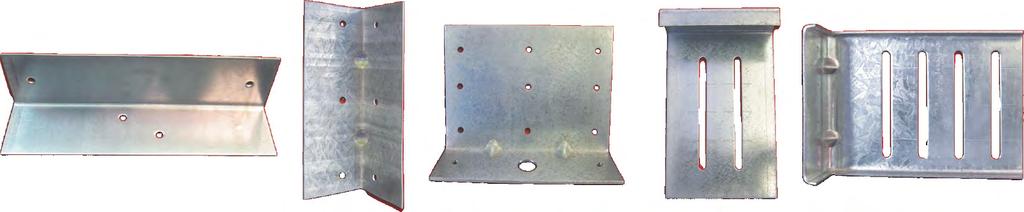
4 DEFLECTION CONNECTORS WSC SLIDE CLIPS WSC Slide clips connect exterior curtain wall studs to the building structure and allow for vertical movement of the building independent of the studs. The WSC series allows for 3 total deflection, 1- up and 1- down. WSC series 14 ga. clips come with extended leg lengths and shouldered screws are provided in each box of clips. 5 pieces per box. MATERIAL: See Table Part WSC36 WSC600 WSC800 WSC1000 WSC100 Ga/Mil Material Finish Size 4 x 1.5 x x 1.5 x x 1.5 x x 1.5 x x 1.5 x #14 Shouldered screws included per box. *(Note: WSC36 includes 50 - #14 shouldered screws per box). WSC100 (10 slots) WSC1000 (8 slots) WSC800 (6 slots) WSC600 (4 slots) WSC36* ( slots) CONCENTRIC TENSION (lbs.) CFS Member # Screws mil mil mil mil ECCENTRIC TENSION (lbs.) CFS Member # Screws mil mil mil mil Deflection Connectors CONCENTRIC COMPRESSION (lbs.) CFS Member # Screws mil mil mil mil ECCENTRIC COMPRESSION (lbs.) CFS Member # Screws mil mil mil mil Allowable loads have not been increased for wind or seismic.. Attachment of WSC clip to main structure should be engineered by a design professional for steel or concrete base materials. 3. Allowable loads are based on attachment to main structure through pilot holes with #10-4 cap screws with a head diameter of Safety factor, Ω, determined in accordance with the provision of section F1. of the NASPEC with statistical data specified in AC61 and from test data. 5. The serviceability limit of 1/8 deflection between the stud and supporting structure did not govern in testing. 6. Eccentric tension and compression values represent clip capacity after structure deflects +_ 1- up or down from center of the clip. 4
5 DEFLECTION CONNECTORS OUTRIGGER Outrigger Slide Clip is used for horizontal surface applications. The outrigger comes in lengths of 18, can be field cut to shorter lengths if needed. Simple and fast to install which saves time and money. One clip fits all stud sizes, no right or left hand clips. MATERIAL: 16 ga (54 mil) 50ksi. DEFLECTION: 1- Total 50 - #14 Shouldered screws provided per box Gauge (Mil) Yield Box Quantity Outrigger 16 (54) 50ksi 5 Connection to Structure Hilti X-U Powder Actuated Fastener in 3/16 Steel Connection to Structure #1-14 Hilti Self Drilling Screws to 3/16 Steel Thickness (mil/ga) of Screws 0ga. (33 mil) 0ga. (33 mil) 4 18ga. (43 mil) 18ga (43 mil) 4 16ga. (54 mil) 16ga. (54 mil) 4 16ga. (54 mil) 50ksi 16ga. (54 mil) 50ksi 4 14ga. (68 mil) 50ksi 14ga. (68 mil) 50ksi 4 of Anchors Allowable Load (lbs.) Thickness (mils/ga) 0ga. (33 mil) 0ga. (33 mil) 4 18ga. (43 mil) 18ga (43 mil) 4 16ga. (54 mil) 16ga. (54 mil) 4 16ga. (54 mil) 50ksi 16ga. (54 mil) 50ksi 4 14ga. (68 mil) 50ksi 14ga. (68 mil) 50ksi 4 of Screws of Anchors Allowable Load (lbs.) Deflection Connectors 1. All anchors must be attached in a single file line down the center of the clip.. All anchor data is from the Hilti 009 Product Technical Guide. 3. All anchors must be attached to structure per manufacturer s instructions. 4. Anchor Spacing for and 3 anchors to be min.. 5. Anchor Spacing for 4 anchors to be 1 min. 6. Anchor edge distance to be min. 5
6 DEFLECTION CONNECTORS WSC 950 & WSC 1500 WSC 950 and 1500 Slide Clips provide lateral support for steel studs and allow for vertical movement of the building structure. They allow for 1- edge of slab tolerance from the existing supporting structure. The WSC Clips accommodate up to vertical movement at intermediate floors and 1- vertical movement at roof levels. They are used in a vertical surface application. Simple and fast to install which saves time and money. One clip fits all stud sizes, no right or left hand clips. Screws must be backed out 1/4 turn once installed. MATERIAL: See Table 4 4- Gauge (Mil) Yield Box Quantity WSC (54) 50ksi 5 WSC (97) 40ksi 5 Screws not included for WSC1500 or WSC950 Deflection Connectors Connection to Structure Hilti X-U Connection to Structure Hilti #1-14 Powder Actuated Fastener in 3/16 Steel Self Drilling Screws to 3/16 Steel WSC 950 WSC 1500 WSC 950 WSC 1500 Stud # of Screws # of Anchors Allowable Allowable Stud Number of Number of Allowable Allowable Thickness to Stud to Structure Load (lbs.) Load (lbs.) Thickness Screws Anchors Load (lbs.) Load (lbs.) ga. (33 mil) 0ga. (33 mil) ga. (33 mil) 0ga. (33 mil) ga. (43 mil) 18ga. (43 mil) ga. (43 mil) 18ga. (43 mil) ga. (54 mil) 16ga. (54 mil) ga. (54 mil) 16ga. (54 mil) ga. (54 mil) 16ga. (54 mil) ksi 50ksi ga. (54 mil) 16ga. (54 mil) ksi 50ksi ga. (68 mil) 14ga. (68 mil) ksi 50ksi ga. (68 mil) 14ga. (68 mil) ksi 50ksi All anchors must be attached in a single file line down the center of the clip, do not use predrilled holes if attaching with PAF.. All anchor data is from the Hilti 009 Product Technical Guide. 3. All anchors must be attached to structure per manufacturer s instructions. 4. All manufacturer s guidelines must be followed for anchor spacing and edge distance. 6
7 DEFLECTION CONNECTORS DEFLEX CLIP Deflex Clips allow up to 1- vertical floor or roof deflection without the use of laborious slip tracks it can be installed with or without standard leg tracks. Simple and fast to install which saves time and money. Two sizes available for 3-5/8, 4, 6 and 8 studs. MATERIAL: 16 ga (54 mil) 50ksi /4-7/8 3T1000 accommodates 3-5/8 and 4 stud widths 6T1000 accommodates 6 and 8 stud widths Gauge (Mil) Yield Box Quantity 3T (54) 50 ksi 5 6T (54) 50 ksi 5 6T T Connection to Structure Hilti X-U Powder Actuated Fastener in 3/16 Steel Deflex Deflex 3T1000 6T1000 Connection to Structure #1-14 Hilti Self Drilling Screws to 3/16 Steel Deflex 3T1000 Deflex 6T1000 Stud Thickness 0ga. (33 mil) 18ga. (43 mil) 16ga. (54 mil) 16ga. (54 mil) 50ksi 14ga. (68 mil) 50ksi # of Screws to Stud # of Anchors to Structure Allowable Load (lbs.) 1. All anchors must be attached in a single file line down the center of the clip.. All anchor data is from the Hilti 009 Product Technical Guide. Allowable Load (lbs.) Stud Thickness Number of Screws Number of Anchors Allowable Load (lbs.) Allowable Load (lbs.) ga. (33 mil) ga. (43 mil) ga. (54 mil) ga. (54 mil) ksi ga. (68 mil) ksi All anchors must be attached to structure per manufacturer s instructions. 4. Anchor edge distance to be min #14 Shouldered screws included DWSC SEISMIC CLIP The DWSC series of clips allow for vertical and lateral movement of the building structure independent of the studs. The DWSC has a total of 3 vertical deflection and total of lateral movement and uses shouldered screws which are included for ease of installation. 5 pieces per box. Part DWSC36 DWSC600 DWSC800 DWSC1000 DWSC100 Ga/Mil Material Finish Size 4 x.5 x x.5 x x.5 x x.5 x x.5 x 11.5 Deflection Connectors 100 #14 Shouldered screws included per box. *(Note: DWSC36 includes 50 - #14 shouldered screws per box) DWSC100 (10 slots) DWSC1000 (8 slots) DWSC800 (6 slots) DWSC600 (4 slots) DWSC36* ( slots) 7
8 RIGID CONNECTORS UTILITY CLIP (UA) - 16 GAUGE Utility Clips are used in a variety of framing applications including floors, walls and roofs. UA clips are pre-cut with pre-drilled holes for easy installation. Utility Clips Leg lengths available from 3-1/4 through 15-. (See table for exact sizes) 1-,, Leg widths available in 1-,, 3 and 4. 3, & 4 Available in 16, 14 and 1 gauge. Pre-punched for faster and more accurate fastener attachment. 3 x 3 Clips available (do not have embossments) See page 1 MATERIAL: See Table for sizes 50ksi Utility Clips are attached to the cold formed steel (CFS) framing members using #10-16 self-drilling screws; using pre-punched holes. * Hole pattern measurements are available on page & F1 F Rigid Connectors 8 UA Clips - 16 Gauge Thickness (mil/ga) Size (in.) Box Qty UA (16 ga) 1-1/ x 1-1/ x 3-1/4 100 UA (16 ga) x x 3-1/4 100 UA (16 ga) 1-1/ x 3 x 3-1/4 100 UA (16 ga) 1-1/ x 4 x 3-1/4 100 UA (16 ga) 1-1/ x 1-1/ x 5-1/4 100 UA (16 ga) x x 5-1/4 50 UA (16 ga) 1-1/ x 3 x 5-1/4 50 UA (16 ga) 1-1/ x 4 x 5-1/4 50 UA (16 ga) 1-1/ x 1-1/ x 7-3/4 50 UA (16 ga) x x 7-3/4 50 UA (16 ga) 1-1/ x 3 x 7-3/4 5 UA (16 ga) 1-1/ x 4 x 7-3/4 5 UA (16 ga) 1-1/ x 1-1/ x 9 50 UA (16 ga) x x 9 50 UA (16 ga) 1-1/ x 3 x 9 5 UA (16 ga) 1-1/ x 4 x 9 5 UA (16 ga) 1-1/ x 1-1/ x 9-3/4 50 UA (16 ga) x x 9-3/4 50 UA (16 ga) 1-1/ x 3 x 9-3/4 5 UA (16 ga) 1-1/ x 4 x 9-3/4 5 UA (16 ga) 1-1/ x 1-1/ x 11-3/4 50 UA (16 ga) x x 11-3/4 50 UA (16 ga) 1-1/ x 3 x 11-3/4 5 UA (16 ga) 1-1/ x 4 x 11-3/4 5 UA (16 ga) 1-1/ x 1-1/ x 13-3/4 50 UA (16 ga) x x 13-3/4 50 UA (16 ga) 1-1/ x 3 x 13-3/4 5 UA (16 ga) 1-1/ x 4 x 13-3/4 5 UA (16 ga) 1-1/ x 1-1/ x 15-3/4 50 UA (16 ga) x x 15-3/4 5 UA (16 ga) 1-1/ x 3 x 15-3/4 5 Screws 7-#10 7-#10 7-#10 7-#10 0ga (33 mil) 33 ksi 18ga (43 mil) 33 ksi 16ga (54 mil) 33 ksi Allowable Load (lbs) 16ga (54 mil) 50 ksi 14ga (68 mil) 50 ksi 1ga (97 mil) 50 ksi F1 F F1 F F1 F F1 F F1 F F1 F UA (16 ga) 1-1/ x 4 x 15-3/ Allowable loads have not been increased for wind or seismic.. Allowable strength shown is the lowest value from the four failure modes: screw tilting/bearing, screw shear, screw pull-over and the serviceability limit state of 1/8 deflection of CFS members. 3. It is the responsibility of design professional to design the connection of UA connectors to the supporting structure. In the test program, this connection was made with cap screws with a head diameter of 0.9. The allowable loads should be conservative for any fastener with a header diameter equal to or greater than F1=Shear, F=Tension
9 RIGID CONNECTORS UTILITY CLIP (UA) - 14 GAUGE Utility Clips are used in a variety of framing applications including floors, walls and roofs. UA clips are pre-cut with pre-drilled holes for easy installation. Leg lengths available from 3-1/4 through 15-. (See table for exact sizes) Leg widths available in 1-,, 3 and 4. Available in 16, 14 and 1 gauge. Pre-punched for faster and more accurate fastener attachment. 3 x 3 Clips available (do not have embossments) See page 1 MATERIAL: See Table for sizes 50ksi Utility Clips are attached to the cold formed steel (CFS) framing members using #10-16 self-drilling screws; using pre-punched holes. 1-,, 3, & 4 Utility Clips 1- & * Hole pattern measurements are available on page F1 F UA Clips - 14 Gauge Thickness (mil/ga) Size (in.) Box Qty UA (14 ga) 1-1/ x 1-1/ x 3-1/4 100 UA (14 ga) x x 3-1/4 100 UA (14 ga) 1-1/ x 3 x 3-1/4 100 UA (14 ga) 1-1/ x 4 x 3-1/4 100 UA (14 ga) 1-1/ x 1-1/ x 5-1/4 100 UA (14 ga) x x 5-1/4 50 UA (14 ga) 1-1/ x 3 x 5-1/4 50 UA (14 ga) 1-1/ x 4 x 5-1/4 50 UA (14 ga) 1-1/ x 1-1/ x 7-3/4 50 UA (14 ga) x x 7-3/4 50 UA (14 ga) 1-1/ x 3 x 7-3/4 5 UA (14 ga) 1-1/ x 4 x 7-3/4 5 UA (14 ga) 1-1/ x 1-1/ x 9 50 UA (14 ga) x x 9 50 UA (14 ga) 1-1/ x 3 x 9 5 UA (14 ga) 1-1/ x 4 x 9 5 UA (14 ga) 1-1/ x 1-1/ x 9-3/4 50 UA (14 ga) x x 9-3/4 50 UA (14 ga) 1-1/ x 3 x 9-3/4 5 UA (14 ga) 1-1/ x 4 x 9-3/4 5 UA (14 ga) 1-1/ x 1-1/ x 11-3/4 50 UA (14 ga) x x 11-3/4 50 UA (14 ga) 1-1/ x 3 x 11-3/4 5 UA (14 ga) 1-1/ x 4 x 11-3/4 5 UA (14 ga) 1-1/ x 11/ x 13-3/4 50 UA (14 ga) x x 13-3/4 50 UA (14 ga) 1-1/ x 3 x 13-3/4 5 UA (14 ga) 1-1/ x 4 x 13-3/4 5 UA (14 ga) 1-1/ x 1-1/ x 1-5-3/4 50 UA (14 ga) x x 15-3/4 5 UA (14 ga) 1-1/ x 3 x 15-3/4 5 UA (14 ga) 1-1/ x 4 x 15-3/4 5 Screws 7-#10 7-#10 7-#10 7-#10 0ga (33 mil) 33 ksi 18ga (43 mil) 33 ksi 16ga (54 mil) 33 ksi Allowable Load (lbs) 16ga (54 mil) 50 ksi F1 F F1 F F1 F F1 F F1 F F1 F ga (68 mil) 50 ksi 1ga (97 mil) 50 ksi 1. Allowable loads have not been increased for wind or seismic.. Allowable strength shown is the lowest value from the four failure modes: screw tilting/bearing, screw shear, screw pull-over and the serviceability limit state of 1/8 deflection of CFS members. 3. It is the responsibility of design professional to design the connection of UA connectors to the supporting structure. In the test program, this connection was made with cap screws with a head diameter of 0.9. The allowable loads should be conservative for any fastener with a header diameter equal to or greater than Rigid Connectors
10 RIGID CONNECTORS UTILITY CLIP (UA) - 1 GAUGE Utility Clips are used in a variety of framing applications including floors, walls and roofs. UA clips are pre-cut with pre-drilled holes for easy installation. Leg lengths available from 3-1/4 through 15-. (See table for exact sizes) Leg widths available in 1-,, 3 and 4. Available in 16, 14 and 1 gauge. Pre-punched for faster and more accurate fastener attachment. 3 x 3 Clips available (do not have embossments) See page 1 MATERIAL: See Table for sizes 50ksi Utility Clips are attached to the cold formed steel (CFS) framing members using #10-16 self-drilling screws; using pre-punched holes. Utility Clips 1-,, 3, & 4 * Hole pattern measurements are available on page & F1 F Rigid Connectors 10 UA Clips - 1 Gauge Thickness Size Box (mil/ga) (in.) Qty Screws UA (1 ga) 1-1/ x 1-1/ x 3-1/4 100 UA (1 ga) x x 3-1/4 100 UA (1 ga) 1-1/ x 3 x 3-1/4 100 UA (1 ga) 1-1/ x 4 x 3-1/4 50 UA (1 ga) 1-1/ x 1-1/ x 5-1/4 100 UA (1 ga) x x 5-1/4 50 UA (1 ga) 1-1/ x 3 x 5-1/4 50 UA (1 ga) 11/ x 4 x 51/4 50 UA (1 ga) 1-1/ x 1-1/ x 7-3/4 50 UA (1 ga) x x 7-3/4 50 UA (1 ga) 1-1/ x 3 x 7-3/4 5 UA (1 ga) 1-1/ x 4 x 7-3/4 5 UA (1 ga) 1-1/ x 1-1/ x 9 50 UA (1 ga) x x 9 5 UA (1 ga) 1-1/ x 3 x 9 5 UA (1 ga) 1-1/ x 4 x 9 5 UA (1 ga) 1-1/ x 1-1/ x 9-3/4 50 UA (1 ga) x x 9-3/4 5 UA (1 ga) 1-1/ x 3 x 9-3/4 5 UA (1 ga) 1-1/ x 4 x 9-3/4 5 UA (1 ga) 1-1/ x 1-1/ x 1-13/4 5 7-#10 UA (1 ga) x x 11-3/4 5 7-#10 UA (1 ga) 1-1/ x 3 x 11-3/4 5 7-#10 UA (1 ga) 1-1/ x 4 x 11-3/4 5 7-#10 UA (1 ga) 1-1/ x 1-1/ x 13-3/4 5 UA (1 ga) x x 13-3/4 5 UA (1 ga) 1-1/ x 3 x 13-3/4 15 UA (1 ga) 1-1/ x 4 x 13-3/4 15 UA (1 ga) 1-1/ x 1-1/ x 15-3/4 5 UA (1 ga) x x 15-3/4 15 UA (1 ga) 1-1/ x 3 x 15-3/4 15 UA (1 ga) 1-1/ x 4 x 15-3/4 15 0ga (33 mil) 33 ksi 18ga (43 mil) 33 ksi 16ga (54 mil) 33 ksi Allowable Load (lbs) 16ga (54 mil) 14ga (68 mil) 50 ksi 50 ksi F1 F F1 F F1 F F1 F F1 F F1 F Allowable loads have not been increased for wind or seismic.. Allowable strength shown is the lowest value from the four failure modes: screw tilting/bearing, screw shear, screw pull-over and the serviceability limit state of 1/8 deflection of CFS members. 3. It is the responsibility of design professional to design the connection of UA connectors to the supporting structure. In the test program, this connection was made with cap screws with a head diameter of 0.9. The allowable loads should be conservative for any fastener with a header diameter equal to or greater than F1=Shear, F=Tension 1ga (97 mil) 50 ksi
11 RIGID CONNECTORS LA CLIP (LARGE UTILITY CLIP) The LA series of clip angles is a series of rigid clips used in a variety of framing applications. Pre-drilled for ease of installation. MATERIAL: See table for sizes 50ksi 3 x 3 LA Clips 3 3-1/4 Size (in.) Box Qty LA x 3 x 3-1/4 100 LA x 3 x 3-1/4 100 LA x 3 x 3-1/4 50 LA x 3 x 5-1/4 50 LA x 3 x 5-1/4 50 LA x 3 x 5-1/4 50 LA x 3 x 7-3/4 5 LA x 3 x 7-3/4 5 LA x 3 x 7-3/ /8 LA / / /8 LA335-1/ /8 LA /8 1- LA Clips Allowable Load (lbs) Thickness Size (mil/ga) Screws (in.) LA (16 GA) 3 x 3 x 3-1/4 6 - #10 LA (14 GA) 3 x 3 x 3-1/4 6 - #10 LA (1 GA) 3 x 3 x 3-1/4 6 - #10 LA (16 GA) 3 x 3 x 5-1/4 6 - #10 LA (14 GA) 3 x 3 x 5-1/4 6 - #10 LA (1 GA) 3 x 3 x 5-1/4 6 - #10 LA (16 GA) 3 x 3 x #10 LA (14 GA) 3 x 3 x #10 LA (1 GA) 3 x 3 x #10 0ga (33 mil) 33 ksi 18ga (43 mil) 33 ksi 16ga (54 mil) 33 ksi 16ga (54 mil) 50 ksi 14ga (68 mil) 50 ksi 1ga (97 mil) 50 ksi Shear Tension Shear Tension Shear Tension Shear Tension Shear Tension Shear Tension Allowable loads have not been increased for wind or seismic.. Allowable strength shown is the lowest value from the four failure modes: screw tilting/bearing, screw shear, screw pull-over and the serviceability limit state of 1/8 deflection of CFS members. 3. It is the responsibility of design professional to design the connection of UA connectors to the supporting structure. In the test program, this connection was made with cap screws with a head diameter of 0.9. The allowable loads should be conservative for any fastener with a header diameter equal to or greater than 0.9. Rigid Connectors 11
12 RIGID CONNECTORS UTILITY CLIP (UA & LA) 1- x 1- Angle Length of Holes 3-1/ / x 4 Angle Length of Holes 3-1/ / /4 1-1/4 x Angle Length of Holes 3-1/ / /4 1-1/4 1- x 3 Angle Length of Holes 3-1/ / Rigid Connectors 3 x 3 Angle Length of Holes 3-1/ / /8-1/8 1- F1 F F1 F 1
13 4" 4" 4" 4" RIGID CONNECTORS RIGID RCC600CLIP CONNECTOR (RCC) with 3 screws pattern RCC600 with 6 screws pattern Rigid Clip Connectors (RCC) are used to rigidly attach the bottom of a parapet stud to the structure, or where high tension or rotational restrain is required. MATERIAL: 1ga (97 mil), 50 ksi FINISH: Galvanized G90 Attach long leg of Rigid Clip Connector to web of stud with #10 16 screws through pre-punched holes. Attach short leg of Rigid Clip Connector to structure with a anchor bolt per Project Engineer s design. RCC800 with 5 screws pattern RCC Clip M1 RCC Loading Conditions RCC800 with 10 screws pattern Allowable Strength of RCC in Moment (M1) Allowable Strength (in-kips) CFS Member Flexibility (Rad/in-lb x10 6 ) RCC358 RCC600 RCC800 Thickness Fy of Screws of Screws (mils/ga) (ksi) (0) (18) (16) (14) (1) Rigid Clip Connector (RCC) 1.50 Stud Dimensions Box Size (in.) Quantity RCC /8 1-1/ x 4 x 3-1/4 50 RCC / x 4 x 5-1/4 50 RCC / x 4 x 7-3/4 5 of Screws Allowable Strength of RCC in Tension/Compression (F) 9 /16 Dia. Hole Allowable Strength of RCC in Shear (F1) CFS Member Allowable Strength (lbs) CFS Member Allowable Strength (lbs) RCC358 RCC600 RCC800 RCC358 RCC600 RCC800 Thickness Fy of Screws of Screws of Screws Thickness Fy of Screws of Screws of Screws (mils/ga) (ksi) (mils/ga) (ksi) (0) , , , (0) (18) , ,578 1, , (18) (16) 50 1,60,116 1,60,1160.5,116, (16) ,000 1,50 1,500 1,860 1, (14) 50 1,640,116 1,640,116,116, (14) ,000 1,50 1,500 1,860 1, (1) 50 1,640,116 1,640,116,116, (1) ,000 1,50 1,500 1,860 1, Tabulated values are based on #10-16 screws with ultimate shear capacity of 1,600 lbs per screw.. Allowable loads have not been increased for wind or seismic. 3. Tabulated loads are based on diameter bolt with Type A plain washer with a nominal outside diameter of 1.06 & nominal thickness of It is the responsibility of the design professional to design the connection of the RCC to the supporting structure. 5. Use linear interaction for combination of F1, F, and M1. 6. The 1/4 thick Heavy Duty Washer (HDW) meets ASTM A36 Standard Specification for Carbon Structural Steel and is made from hot rolled flat bar and painted gray for corrosion resistance. 5-1/4" 3-1/4" 5-1/4" 5-1/4" 7-3/4" 7-3/4" 7-3/4" Rigid Connectors 4" 4" 4" 4" 4" 4" 4" 4" RCC600 with RCC358 3 screws RCC358 & pattern RCC600 with 3 screws pattern RCC600 RCC358 with 6 screws & pattern RCC600 with 6 screws pattern with screws RCC800 pattern with 5 screws pattern with 10 screws RCC800 pattern with 10 screws pattern 13
14 RIGID CONNECTORS RIGID CLIP CONNECTOR WITH HDW WASHER Rigid Clip Connectors (RCC) are used to rigidly attach the bottom of a parapet stud to the structure, or where high tension or rotational restrain is required. MATERIAL: 1/4 Carbon Structural Steel Hot Rolled Heavy Duty Washer (HDW), 36 ksi FINISH: HDW washer is painted gray for corrosion resistance. Attach long leg of Rigid Clip Connector to web of stud with #10 16 screws through pre-punched holes. Attach short leg of Rigid Clip Connector to structure with a anchor bolt per Project Engineer s design. Allowable Strength of RCC with HDW (Washer) in Moment (M1) CFS Member Thickness (mil/ga) Fy (ksi) 33 (0) (18) (16) (14) (1) 50 Allowable Strength (in-kips) Flexibility (Rad/in-lb x10 6 ) RCC358 RCC600 RCC800 of Screws of Screws of Screws HDW Heavy Duty Washer (HDW) RCC Clip with HDW 9 /16 Dia. Hole Stud Size Dimensions (in.) Box Quantity HDW /8 1/4 x 1-5/16 x 3-1/4 50 HDW /4 x 1-5/16 x 5-1/4 50 HDW /4 x 1-5/16 x 7-3/ Allowable Strength with HDW (Washer) in Shear (F1) Allowable Strength with HDW (Washer) in Tension/Compression (F) 0 Rigid Connectors CFS Member Thickness Fy (mils/ga) (ksi) 33 (0) (18) (16) (14) (1) /16 9 /16 Dia. Dia. Hole Hole Allowable Strength (lbs) RCC358 RCC600 RCC800 of Screws of Screws of Screws ,070 1,100 1,450 1, ,160,160 1,070 1,100 1,450 1,670, ,160 1,070 1,100 1,450 1,670,160,160 CFS Member Thickness (mils/ga) Allowable Strength (lbs) RCC358 RCC600 RCC800 of Screws of Screws of Screws , , , , ,578 1, ,630 1,60 3,05 1,60,19,671 3,44 1,640 3,44 1,640 3,05,733 3,44 1,640 3,44 1,640 3,44,733 3,44 1. Tabulated values are based on #10-16 screws with ultimate shear capacity of 1,600 lbs per screw Allowable loads have not been increased for wind or seismic. 3. Tabulated loads are based on diameter bolt with Type A plain washer with a nominal outside diameter of 1.06 & nominal thickness of It is the responsibility of the design professional to design the connection of the RCC to the supporting structure. 5. Use linear interaction for combination of F1, F, and M1. 6. The 1/4 thick Heavy Duty Washer (HDW) meets ASTM A36 Standard Specification for Carbon Structural Steel and is made from hot rolled flat bar and painted gray for corrosion resistance. Fy (ksi) 33 (0) (18) (16) (14) (1) /4" 3-1/4" 5-1/4" 7-3/4" 7-3/4" 4" 4" 4" 4" 4" 4" 4" 4" 4" 4" 4" 4" 4" tern attern RCC358 RCC600 RCC358 & RCC600 with 3 pattern with 3 screws pattern RCC358 RCC600 & RCC600 with with 66 6 with 6 screws pattern RCC800 with with 5 with 5 screws 5 5 pattern RCC800 with with 10 with 10 screws 10 pattern 14
15 RIGID CONNECTORS HOLDOWN (S/HD & S/HDS) The S/HD series of holdowns is designed for installation with either screws or bolts into the studs or column. The S/HDS series installs with #14 screws and has been designed to utilize fewer fasteners to reduce installation time. The S/HDB series is ideal for bolt-on applications where the cold-formed stud manufacturer can re-punch the bolt holes. MATERIAL: S/HD8 and S/HD mil (10 ga) with 3/8 plate, S/HD mil (7 ga) with plate. FINISH: Simpson gray paint. Hot-dip galvanized is available. Use all specified fasteners. The design engineer may specify any alternate anchorage calculated to resist the tension load for your specific job. Anchor bolt washer is not required. S/HD10 (S/HD10S similar) Dimensions (in.) Fasteners Anchor Allowable Tension Loads (133) Back-to-Back Stud 43 mil ( 18 ga.) 33 mil. ( 0 ga.) W H CL Dia. Screws S/HD8-1/ 13-7/8 1-1/ 7/8 4-# S/HD10-1/ 16-1/8 1-1/ 7/8 30-# S/HD15-3/4 1-1/ 1-1/ 1 48-# S/HD8S -5/ / 7/8 17-# S/HD10S -5/ / 1-1/ 7/8 -# S/HD15S -7/ / # For load at (100), multiply table value by 0.75 where the 1/3 increase is not permitted.. Values are test limited. For load at (100), no reduction necessary. For load at (133) for 1/3 increase, no further increase allowed. 3. The Designer shall specify the anchor embedment and configuration. 4. Deflection at Highest allowable Design Load: The deflection of a holdown measured between the anchor bolt and the strap portion of the holdown when loaded to the highest allowable load listed in the catalog table. This movement is strictly due to the holdown deformation under a static load test conducted on a steel jig. 54 mil ( 16 ga.) Holdown Deflection at Highest Allowable Design Load S/HD15 TENSION TIE (S/LTT & S/HTT) The S/HTT14 is a single-piece formed tension tie no rivets, and a 4-ply formed seat which won t unfold during loading. No washers are required. The S/LTT and S/HTT Tension Ties are ideal for retrofit or new construction projects. They provide high strength, post-pour, concrete-to-steel connections. MATERIAL: See table. Use all specified fasteners. Use the specified number and type of screws to attach the strap portion to the steel stud. Bolt the base to the wall or foundation with a suitable anchor; see table for the required bolt diameter. S/HTT14 Rigid Connectors Material (mil/ga) Strap Plate Dimensions (in.) Fasteners Allowable Tension Holdown Deflection Anchor Loads at Highest Allowable W H CL Bolts Screws (133) Design Load S/LTT0 97 (1 ga) 9 (3 ga) 0 1-1/ 1/ 8 # S/HTT (11 ga) -1/ /4 5/8 14 # The Designer shall specify the anchor embedment and configuration.. Load at (100), no reduction necessary. Load at (133) for 1/3 increase, no further increase allowed. 3. Loads are based on attachment of CFS members having a minimum thickness of 33 mil (0 ga). 4. Deflection at Highest allowable Design Load: The deflection of a holdown measured between the anchor bolt and the strap portion of the holdown when loaded to the highest allowable load listed in the catalog table. This movement is strictly due to the holdown deformation under a static load test conducted on a steel jig. S/LTT0 15
16 RIGID CONNECTORS WRC RIGID CLIPS The WRC series of clips connects exterior studs to the building structure and resists horizontal and lateral loads. The WRC has embossments and a continuous flange to allow for excellent load values. 5 pieces per box. Part WRC36 WRC600 WRC800 WRC1000 WRC100 Ga. (Mil) Material Finish Size 4 x 1.5 x x 1.5 x x 1.5 x x 1.5 x x 1.5 x 11.5 WRC100 WRC1000 WRC800 WRC600 WRC36 Rigid Connectors GUSSET PLATE (UNPUNCHED) (GP) Designed for a variety of construction connections. Used for conditions such as roof, wall and floor framing connections. GPU Plate is used for in plane truss chord connections, header to jamb connections and tension strap connections. Adapts to varying construction tolerances. MATERIAL: See Table, 50ksi FINISH: Galvanized coating weight as requested. As specified by design. 16 Gauge (54 mils).0566 Design Thickness 1 Gauge (97 mils).1017 Design Thickness Custom sizes available upon request. Gusset Plate (Unpunched) Gauge Size GPU x6 GPU x1 GPU x1 GPU x6 GPU x1 GPU x1 16
17 FRAMING CONNECTORS SOLID BLOCKING (JB) Blocking is pre-cut to fit securely between joists to prevent joist rotation. Blocking is a one piece system in lieu of the typical 3 piece detail offering an economical alternative to installing conventional clips and solid web members. MATERIAL: 16 ga (54 mil) 50ksi Position the pre-cut Blocking to fit securely between the joists. (4) #10-16 screws are required to secure the blocking to the joist flanges using the pre-punched holes. Solid blocking should be installed 7 o.c. maximum along the joist length. Fits up to flange product. Blocking for - and 3 flanges available as a special order. H (1 O.C.) (16 O.C.) (4 O.C.) Size (H) Spacing (o.c.) Box Quantity 800JB JB-1 9-1/ JB JB / JB JB SB JB JB / JB JB / JB JB JB JB-4 9-1/ JB JB / JB JB Joist Blocking Solid Blocking StudRite Blocking 6 or greater WEB STIFFENER (JS) Web Stiffeners are used to provide reinforcement of joist webs to prevent crippling. Web reinforcement is often required by design to enhance the load capacity of joists. Web stiffeners are installed on the inside or outside of the joist. MATERIAL: 16 ga (54 mil) 50ksi Web stiffeners are centered within the load or reaction bearing width. Web stiffeners require full bearing along their supported ends. (4-6) #10-16 screws are required to attach the stiffener to the joist web using pre-punched holes. Joist Size Height (H) 8JS /16 95JS /4 8-15/16 10JS /16 115JS / /16 1JS /16 14JS /16 Box Quantity Web Stiffener 1-1/4 3-5/8 H Joist Framing Connectors 5/8 17
18 JOIST FRAMING CONNECTORS BH JOIST HANGER The BH Joist hanger is used to connect floor joists to the supporting structure. GAUGE (MIL) YIELD: 1 (97) 50ksi OPTIONS: Single BH Hanger: W=-1/8 for Flange Joist Double BH Hanger: W=4-1/4 for Flange Joists Tripple BH Hanger: W=6-3/8 for all Flange Joists - - H 800BH1 100BH1 10BH1 140BH1 160BH1 800DB1 100DB1 10DB1 140DB1 160DB1 800TBH1 100TBH1 10TBH1 140TBH1 160TBH1 *Call for other sizes W (in) -1/8 4-1/4 6-3/8 H (in) The height values (H) measured from the inside dimension from the seat of the hanger to the outside dimension at the top of the hanger. B W BH - Screw BH - Welded BH - P.A.F. Dimensions W (in) H (in) B (in) See See table table - Fastners 6-#10 Screws 1/8 x Weld 6-P.A.F. fasteners Allowable Downloads Loads are governed by tests and may not be increased.. The joist must be properly seated in the hanger. 3. Header to be engineered by a design professional 4. Powder actuated fastener and welded loads are based on hanger attached to 3/8 structural steel member. 5. Loads for screw attached hanger were based on hanger attached to 68 mil CFS member. 6. Powder actuated fastener loads were tested with Hilti X-U Pins. 7. BH hangers were tested per AISI S914-08, Test Standard for Joist Connectors Attached to CFS framing. Joist Framing Connectors BH Hanger application 3 Screws or pins in ea - Flange minimum m 18
19 BRIDGING & BRACING CONNECTORS BRIDGERITE CLIP (BR) BridgeRite Clips are ready for use to attach cold rolled channel to wall studs. This easy to use clip will save time and money from having to cut longer length angles down to size. MATERIAL: 16 ga (54) 50ksi Attach BridgeRite clip to web of stud and cold rolled channel #10-16 screws through prepunched holes. Size Box Quantity BRC3 3-1/4, BRC6 6, Lengths 3-1/4, COILED STRAP (CS) CS are continuous utility straps which can be cut to length on the job site. Packaged in lightweight (about 40 pounds) cartons. MATERIAL: 33 mil (0 ga), 43 mil (18 ga) & 54 mil (16 ga) Use all specified fasteners. Refer to the applicable code for minimum edge and end distances. The table shows the maximum allowable loads and the screws required to obtain them. See footnote #1. Fewer screws may be used; reduce the allowable load by the code lateral load for each fastener subtracted from each end. Coiled Strap Length Material Thickness (mil/ga) Width Fasteners (Total) Rafter/Stud/Joist Thickness 33 mil 43 mil (0ga) (18ga) Allowable Tension Loads 33 mil (0ga), 43 mil (18ga) & 54 mil (16ga) 54 mil (16ga) (100) (133) CS (16ga) 1-1/4 18 #10 1 #10 8 # CS (18ga) 1-1/4 14 #10 10 #10 6 # CS (0ga) 1-1/4 1 #10 8 #10 6 # Use half of the fasteners in each member being connected to achieve the listed loads.. For CS straps: End Length (inches) = 1/ total fasteners Total Cut Length = End Length + Clear Span + End Length. 4. For a reduced number of screws, allowable load = (#screws used/#screws in table) x table load. 5. Loads are based on lesser of steel strap capacity and 001 AISI NASPEC fastener calculation. 6. Tabulated loads shown at (100) do not include steel stress increase. Tabulated loads shown at (133) include a 1/3 stress increase on the steel. Typical CS installation as a floor-to-floor tie 19 Bridging & Bracing
20 BRIDGING & BRACING CONNECTORS KATZ BLOCKING (KB) Katz Blocking has been designed to provide top of wall attachment between parallel framing members. Product is pre-punched to work in 16 and 4 spacing of parallel framing members of wood or steel. MATERIAL: See Table. 18 ga (43 mil) ; 0 ga (30 mil) ; 5 ga (18 mil) FINISH: Galvanized G40 Insert the pre-cut structural blocking to fit securely between the underside of the floor/ceiling joist or roof trusses. Using #8 minimum self-drilling screws secure the blocking to steel framing of #8d nail to wood framing using the pre-punched holes. Use Katz blocking at 4 o.c. or maximum specified. 3-5/8 1-1/4 16 or 4 (from screw to screw) Length Gauge Size Pallet Qty KATZ /8 500 KATZ /8 500 KATZ /8 500 KATZ /8 00 KATZ /8 00 Bridging & Bracing SBR & DBR SPACER BRACERS Simpson Strong-Tie introduces the SBR and DBR spacer bracers for cold-formed steel construction. These spacer bracers reduce the installed cost of cold-formed steel stud walls by enabling faster stud layout while minimizing the need for bridging clips. MATERIAL: SBR/43 43 mil (40 ksi); DBR/30 7 mil (33 ksi) FINISH: Galvanized (G90) Spacer-bracers are fed through the stud knockout at a 90-degree angle until studs align with spacer-bracer slots. With the slots engaging the stud web, the spacerbracer is then rotated back to the flat position so that the slotted flanges are on the bottom. For off-layout or end-of-run studs where a spacerbracer slot does not engage a stud, manually snip the spacer-bracer flanges with a ½ deep slot and secure the spacer bracer to the stud with Simpson Strong-Tie LSSC or RCA connectors. Use all specified fasteners. Wear gloves while handling and installing spacer bracers. 0

21 SPECIALTY PRODUCTS SUBH BRIDGING CONNECTORS Simpson Strong-Tie SUBH and MSUBH wall stud bridging connectors for cold-formed steel (CFS) framing offer a compact profile that allows standard 1 5/a studs to be sistered directly against adjacent studs. The LSUBH connector provides the same installation benefits of the SUBH/MSUBH connectors, and is suitable for many wind- and load-bearing situations where the load demand is light to moderate. Many applications require only one screw, greatly reducing labor costs and increasing productivity. MATERIAL: LSUBH mil (0 ga.); SUBH mil (18 ga.); MSUBH mil (14 ga.) FINISH: Galvanized G90 Bracing for Laterally Loaded C-Studs Calculate required bracing force for each flange using equation D Select connector with tabulated allowable torsional moment that exceeds the torsional moment from Step for the stud depth and gauge required. Bracing Design for Axially Loaded C-Studs Calculate required LRFD brace strength using equation D3.3-1 Divide result by 1.5 for ASD design 1 Calculate required brace stiffness using equation D3.3- Select connector with tabulated allowable brace strength that exceeds stiffness from Step 3 for the stud depth and gauge required. 1. Page III-54 of the 008 edition of the AISI Cold-Formed Steel Design Manual states that equation D3.3-1 is applicable to LRFD design, and recommends dividing the result by 1.5 for ASD design. GROMMET Grommets snap easily into stud and joist knockouts. They are used to protect electrical wiring and plumbing lines from contacting metal. Grommets can be used in commercial and residential construction for stud sizes of 3- and larger. Install grommets in all stud knockouts where wiring and plumbing lines will be inserted. Simple one piece snap in installation. 5 parts to a bag/500 to a box. Specialty Products 1
 Breakaway Clips are manufactured from aluminum and designed to melt under extreme heat allowing a fire damaged structure to collapse while permitting the")
22 SPECIALTY PRODUCTS BREAKAWAY CLIP (BA) Breakaway Clips are manufactured from aluminum and designed to melt under extreme heat allowing a fire damaged structure to collapse while permitting the fire wall to remain in place to protect adjacent units. MATERIAL: Aluminum.063 Must be used in conjunction with Area Separation Wall Systems. Attach the Breakaway Clip to the completed Area Separation Wall Assembly. One Clip should be located at each side of each H Stud. Fasten BA Clip to H Stud with a screw through pre-punched holes. Attach to wood or steel adjacent framing with nails or screws respectively. 3 ALCL ALCL WALL SECTION ASSEMBLY Wood or Steel Stud 1 Liner Board Insulation Gypsum Board (any UL classified) H-Stud C-Runner (back to back) Breakaway Clip Subfloor Floor joists or trusses Air space between H-stud and steel/wood framing or GenieClip SOUND ISOLATION CLIP An innovative, and reliable sound solution Engineered for superior acoustical performance in reducing the transmission of airborne and impact sound through wall and floor/ceiling assemblies. The GenieClip is a unibody molded rubber and galvanized steel mount used to attach Gypsum Wallboard (GWB) to either wall or floor/ceiling assemblies. Made from recycled components, and engineered to allow reduction in assembly weight, the GenieClip contributes to LEED certified building. Specialty Products 40 UL certifications Over 150 independent laboratory and field test reports Installation instructions Complete laboratory test reports and field data Technical papers Performance comparisons Cost analysis Case studies Private website for engineers LEED information and carbon footprint analysis Technical binder request Local Sales support in U.S., U.K., Canada, Middle East and Southeast Asia

23 Warranty & Limitations All products presented herein are warranted to the buyer to be free from defects in material and workmanship. The foregoing warranty is nonassignable and in lieu of and excludes all other warranties not expressly set forth herein, whether express or implied by operation of law or otherwise, including but not limited to any implied warranties of merchantability or fitness for a particular purpose. All details and specifications presented herein are intended as a general guide for the use of Marino\WARE framing systems. These products should not be used without evaluation by a qualified engineer or architect to determine their suitability for a specific use. Marino\WARE assumes no responsibility for failure resulting from use of its details or specifications, or for failure resulting from improper application or installation of these products. Governing Law All issues arising in connection with your order and all transactions associated with it shall be interpreted according to the laws of the State of New Jersey, and all actions or other proceedings arising out of such issues shall be brought only in Superior Court, State of New Jersey, County of Essex, or United States District Court for the District of New Jersey. No action may be brought more than one year after accrual of the cause of action therefore. 3


24 100% American-Owned and Operated marinoware.com New Jersey Facility 400 Metuchen Road South Plainfield, NJ Fax: Georgia Facility 777 Greenbelt Parkway Griffin, GA Fax: Indiana Facility 445 Railroad Avenue East Chicago, IN Fax: Texas Facility Bay Area Boulevard Pasadena, TX Fax: New York Sales Office 137 Broadway, Suite B1 Amityville, NY Fax: Engineering Office 100 Hendrick Drive, Suite 00 McDonough, GA Fax:
DIVISION: METALS SECTION: COLD-FORMED METAL FRAMING REPORT HOLDER: WARE INDUSTRIES D/B/A MARINO\WARE
 0 Most Widely Accepted and Trusted ICC-ES Report ICC-ES 000 (800) 423-6587 (562) 699-0543 www.icc-es.org ESR-3578 Reissued 0/206 This report is subject to renewal 0/208. DIVISION: 05 00 00 METALS SECTION:
STRONGER THAN STEEL. interior and exterior framing
 ROUGH OPENINGS PRODUCT CATALOG STRONGER SM THAN STEEL. interior and exterior framing rough openings ROUGH OPENINGS M A D E E A S Y. Rough openings have always been a challenge on the jobsite. At ClarkDietrich,
GENERAL INFORMATION 600-QFH QFJ APPLICATIONS CODES AND STANDARDS PRODUCT DATA
 TECHNICAL GUIDE GENERAL INFORMATION The QuickFrame Rough Opening System streamlines installation by reducing the number of components required to frame windows and doors. The QuickFrame system comes in
ROUGH OPENINGS PRODUCT CATALOG STRONGER THAN STEEL. INTERIOR AND EXTERIOR FRAMING
 PRODUCT CATALOG STRONGER SM THAN STEEL. INTERIOR AND EXTERIOR FRAMING MADE EASY. Rough openings have always been a challenge on the jobsite. At ClarkDietrich, we make them easy. Our collection of rough
Supreme. Supreme Framing System. Product Catalog IAPMO UNIFORM ER #0313
 Supreme Supreme Framing System Product Catalog IAPMO UNIFORM ER #0313 2507 Table of Contents Certification of Materials 5 LEED Credits 5 Independent Product Certification 5 Code Approvals, Performance
2507 (IBC 2006 ONLY) 3054 (IBC 2006 ONLY) Supreme Framing System Product Catalog
 3054 (IBC 2006 ONLY) Supreme Framing System Product Catalog") 12 0 2 / 2009IANT C B I PL COM 2507 (IBC 2006 ONLY) 3054 (IBC 2006 ONLY) R Supreme Framing System Product Catalog Supreme Framing System The Benefits of Supreme Framing System Speak for Themselves What
12 0 2 / 2009IANT C B I PL COM 2507 (IBC 2006 ONLY) 3054 (IBC 2006 ONLY) R Supreme Framing System Product Catalog Supreme Framing System The Benefits of Supreme Framing System Speak for Themselves What
GENERAL INFORMATION FEATURES.
 TECHNICAL GUIDE GENERAL INFORMATION SUPERIOR ENGINEERED JOIST SYSTEMS JoistRite is a specially designed, patented, cold-formed steel section that has one of the highest strength-to-mass ratios of any structural
WARRANTY AND LIMITATIONS
 2 GENERAL INFORMATION QUALITY AND SERVICE COUNT Marino\Ware is proud to present this catalog that details our Lightweight Steel Framing Products. For over 70 years, Marino\Ware has been providing their
U.S. PATENT NO.: US 7,765,771 TECHNICAL GUIDE SUPERIOR ENGINEERED FLOOR FRAMING SYSTEM
 U.S. PATENT NO.: US 7,765,771 TECHNICAL GUIDE SUPERIOR ENGINEERED FLOOR FRAMING SYSTEM SUPERIOR ENGINEERED JOIST SYSTEMS JoistRite is a specially designed, patented, cold-formed steel section that has
Expanding Your Solutions. Steel Framing and Accessories. ICC ESR and 2015 IBC, IRC
 Expanding Your Solutions Steel Framing and Accessories ICC ESR-30 20 and 2015 IBC, IRC Effective 1/4/2017 Table of Contents Introduction to CEMCO... 1 Product Identification... 2 3 LEED Certification...
IBC 2009/2012 COMPLIANT. Supreme Framing System. Product Catalog
 IBC 2009/2012 COMPLIANT 2507 Supreme Framing System Product Catalog Supreme Framing System The Benefits of Supreme Framing System Speak for Themselves What is the Supreme Framing System? Supreme Framing
Overview. HDS replaces built-up curtain wall headers. HDS replaces load-bearing box beam headers
 Overview The Heavy-Duty Stud (HDS ) Framing System is a high-performance, costeffective, multipurpose, heavy-duty framing stud for headers, jambs, posts and built-up tube truss chords and webs. The superior
Expanding Your Solutions. ViperStud Product Catalog. Interior Non-Load Bearing Studs and Track
 Expanding Your Solutions ViperStud Product Catalog Interior Non-Load Bearing Studs and Track Effective 5/11/18 #VSB5-5/15 By providing a lighter, stronger, more efficient framing system, ViperStud has
Connectors catalog 6/22/09 3:17 PM Page 1 CONNECTORS PRODUCT INFORMATION CONNECTOR PLATES TRUSS BRACING & RESTRAINING PRODUCTS.
 Connectors catalog 6/22/09 3:17 PM Page 1 CONNECTORS PRODUCT INFORMATION CONNECTOR PLATES TRUSS BRACING & RESTRAINING PRODUCTS www.mii.com TM Connectors catalog 6/22/09 3:17 PM Page 2 MITEK QUALITY & SERVICE
DeltaStud - Lightweight Steel Framing
 DeltaStud - Lightweight Steel Framing B C H A t P Load Tables for Wind Bearing and Combined Wind & Axial Load Bearing Condition January 2014 Table of Contents Commentary Introduction...3 Product Identification...3
Bridge Overhang Brackets
 Bridge C49, C49D, C49S and C49JR Bridge Dayton Superior offers the bridge contractor four different Horizontal Length versions of the C49 Bridge Bracket, which allows for maximum adjustability to meet
LETTER OF TRANSMITTAL
 FRANK A. ANZALONE Date: FAA Job No. GENERAL CONTRACTOR 1401 Derek Drive, Suite B Hammond, LA 70403 Phone: (985) 542-2744 Fax: (985) 230-0614 Attention: RE: LETTER OF TRANSMITTAL WE ARE SENDING YOU Attached
The following excerpt are pages from the North American Product Technical Guide, Volume 1: Direct Fastening, Edition 15.
 The following excerpt are pages from the North American Product Technical Guide, Volume 1: Direct Fastening, Edition 15. Please refer to the publication in its entirety for complete details on this product
Revision and Errata List AISC Steel Construction Manual, 13 th Edition, Third Printing (Revision 2 June 2010)
") Revision and Errata List AISC Steel Construction Manual, 13 th Edition, Third Printing (Revision 2 June 2010) The following list represents corrections that have been made in the Fourth Printing of the
Revision and Errata List AISC Steel Construction Manual, 13 th Edition, Third Printing (Revision 2 June 2010) The following list represents corrections that have been made in the Fourth Printing of the
western for products manufactured in White City, Oregon
 western VERSA-LAM SPECIFIER Guide for products manufactured in White City, Oregon Western VERSA-LAM Guide 11/29/2012 2 VERSA-LAM Products An Introduction to VERSA-LAM Products When you specify VERSA-LAM
Table of Contents. PrimeJoist
 JamStud Introduction Table of Contents PrimeJoist Introduc on...1 Fire & Sound Tested Assemblies...2 PrimeJoist Design Considera ons...3-4 PrimeJoist Product Profile...5 PrimeJoist Sec on Proper es...6
STRONGER. COLD-FORMED STRUCTURAL FRAMING PRODUCTS technical design guide
 COLD-FORMED STRUCTURAL FRAMING PRODUCTS technical design guide STRONGER T H A N S T E E L. SM M E M B E R P R O P E R T I E S & S PA N S C U R TA I N WA L L S L O A D -B E A R I N G WA L L S J O I S T
DIVISION: METALS SECTION: STEEL DECKING REPORT HOLDER: CONSOLIDATED SYSTEMS, INC. (CSi )
") 0 ICC-ES Report ICC-ES (800) 423-6587 (562) 699-0543 www.icc-es.org 000 Most Widely Accepted and Trusted ESR-2839 Reissued 05/2015 This report is subject to renewal 05/2016. DIVISION: 05 00 00 METALS SECTION:
0 ICC-ES Report ICC-ES (800) 423-6587 (562) 699-0543 www.icc-es.org 000 Most Widely Accepted and Trusted ESR-2839 Reissued 05/2015 This report is subject to renewal 05/2016. DIVISION: 05 00 00 METALS SECTION:
WESTERN SPECIFIER. Technical Data for PWI Joists, PWLVL Headers, Beams, Rim Board, Stud, and Dimension
 E N G I N E E R E D W O O D WESTERN SPECIFIER Technical Data for PWI Joists, PWLVL Headers, Beams, Rim Board, Stud, and Dimension P R O D U C T S JOIST DIMENSIONS 9½ LVL FLANGE PWI JOIST SERIES JOIST DIMENSIONS
Allowable Holes in VERSA-LAM Beams
 VERSA-LAM Products 23 An Introduction to VERSA-LAM Products When you specify VERSA-LAM laminated veneer headers/beams, you are building quality into your design. They are excel lent as floor and roof framing
REPORT HOLDER: CLARKDIETRICH BUILDING SYSTEMS 9050 CENTRE POINTE DRIVE, SUITE 400 WEST CHESTER, OHIO EVALUATION SUBJECT:
 0 Most Widely Accepted and Trusted ICC ES Evaluation Report ICC ES 000 (800) 423 6587 (562) 699 0543 www.icc es.org ESR 1464 Reissued 01/2018 This report is subject to renewal 01/2019. DIVISION: 05 00
Ford Fabricated Steel Products
 Ford Fabricated Steel Products Section N2 12/2000 The Ford Meter Box Co., Inc. 775 Manchester Avenue, P.O. Box 443, Wabash, Indiana, USA 46992-0443 Telephone: 219/563-3171 FAX: 1-800-826-3487 Overseas
ESR-1414 Reissued October 1, 2011 This report is subject to renewal in one year.
 ICC-ES Evaluation Report www.icc-es.org (00) 23-657 (562) 699-053 ESR-11 Reissued October 1, 2011 This report is subject to renewal in one year. A Subsidiary of the International Code Council DIVISION:
Purlins and Girts. A division of Canam Group
 Purlins and Girts A division of Canam Group TABLE OF CONTENTS OUR SOLUTIONS AND SERVICES............................................................ 5 Cautionary statement..................................................................
Light gage steel framing
 Missouri University of Science and Technology Scholars' Mine Center for Cold-Formed Steel Structures Library Wei-Wen Yu Center for Cold-Formed Steel Structures 1-1-2001 Light gage steel framing Dale Industries
SECTION METAL LOCKERS. A. ADAAG Americans with Disabilities Act, Accessibility Guidelines.
 SECTION 10 51 13 METAL LOCKERS PART 1 GENERAL 1.01 SECTION INCLUDES A. Heavy Duty Welded Gear Lockers. B. Locker benches. 1.02 REFERENCES A. ADAAG Americans with Disabilities Act, Accessibility Guidelines.
STANDARD SPECIFICATIONS
 American National Standard SJI-K 1.1 STANDARD SPECIFICATIONS FOR OPEN WEB STEEL JOISTS, K-SERIES SECTION 1. SCOPE Adopted by the Steel Joist Institute November 4, 1985 Revised to November 10, 2003 - Effective
ESR-1414 Reissued July 2014 This report is subject to renewal October 1, 2015.
 ICC-ES Evaluation Report www.icc-es.org (00) 23-6 (62) 699-03 ESR-11 Reissued July 201 This report is subject to renewal October 1, 201. A Subsidiary of the International Code Council DIVISION: 0 00 00
HORIZONTAL SYSTEMS SOME SAY WE OVER-ENGINEER LIFELINES. WE SAY YOU CAN T OVER-DO SAFETY.
 SOME SAY WE OVER-ENGINEER LIFELINES. WE SAY YOU CAN T OVER-DO SAFETY. 90 You can always depend on our horizontal safety systems for mobility and fall protection when working at height. That s why safety
Rosboro TM. Next-Generation Glulam. n Architectural Appearance. n Full Framing-Width Stock. Glulam. n I-Joist and Conventional.
 n Architectural Appearance n Full Framing-Width Stock Glulam n I-Joist and Conventional Depths 2 X-Beam: X-Beam is the building industry s first full framing-width stock glulam in architectural appearance.
1-3/8" inside-to-inside dimension. length of the leg. S162
 Member Designation MEMBER DEPTH: FLANGE WIDTH: STIFFENER LIP: Member Depths are taken in 1/100 inches. Flange Widths are taken in 1/100 inches. Member Flange Width Stiffener Lip (in) For Track Sections,
December 1, Table of Contents. TABLE TOPIC PAGE General TABLE TOPIC PAGE. Roof Decks (continued) (Diaphragm Shear Values)
 (Diaphragm Shear Values)") Page 1 of 57 Table of Contents Report ER-78P December 1, 02 TABLE TOPIC PAGE General 1 Allowable Shear Values - Spot or Seam Welds 2 2 Allowable Tension Loads - Hilti Fasteners... 2 3 Allowable Shear and
Page 1 of 57 Table of Contents Report ER-78P December 1, 02 TABLE TOPIC PAGE General 1 Allowable Shear Values - Spot or Seam Welds 2 2 Allowable Tension Loads - Hilti Fasteners... 2 3 Allowable Shear and
GP Lam LVL. Grade Thickness Depth , , , , , 149, 169, 189, 249 (209and 229 by special order) 2.
 2.") GP Lam LVL Grade Thickness Depth 2.0E 1 3 49, 3 1 29 7 1 49, 9 1 49, 9 1 29, 11 1 49, 11 7 89, 149, 169, 189, 249 (209and 229 by special order) 1.5E 1 3 49 7 1 49, 9 1 49, 9 1 29, 11 1 49, 11 7 89, 149,
GP Lam LVL Grade Thickness Depth 2.0E 1 3 49, 3 1 29 7 1 49, 9 1 49, 9 1 29, 11 1 49, 11 7 89, 149, 169, 189, 249 (209and 229 by special order) 1.5E 1 3 49 7 1 49, 9 1 49, 9 1 29, 11 1 49, 11 7 89, 149,
GP Lam LVL. Grade Thickness Depth , 9 1 4, 9 1 2, , , 14, 16, 18, 24 (20 and 22 by special order) 2.
 2.") GP Lam LVL GP Lam LVL Introduction.....................32 Bearing Details...................34 Handling and Installation..........35 Floor Beams.....................35 Window, Patio Door and Garage Door
GP Lam LVL GP Lam LVL Introduction.....................32 Bearing Details...................34 Handling and Installation..........35 Floor Beams.....................35 Window, Patio Door and Garage Door
ROOFING SOLUTIONS DESIGN GUIDE PURLINS AND GIRTS DESIGN GUIDE PURLINS AND GIRTS S&T029N
 DESIGN GUIDE PURLINS AND GIRTS ROOFING SOLUTIONS DESIGN GUIDE PURLINS AND GIRTS S&T029N JUL 2015 CONTENTS INTRODUCTION 2 Acknowledgements 2 Disclaimer 2 Product Technical Statement 3 Producer Statement
FREE STANDING WORK STATION JIB CRANE
 SECTION 14661 FREE STANDING WORK STATION JIB CRANE ***** Gorbel, Inc. manufacturers a broad range of material handling cranes including monorail, bridge, gantry, and jib cranes. Numerous work station and
DIVISION: METALS SECTION: STEEL DECKING REPORT HOLDER: 2100 REXFORD ROAD CHARLOTTE, NORTH CAROLINA EVALUATION SUBJECT:
 0 Most Widely Accepted and Trusted ICC ES Evaluation Report ICC ES 000 (800) 3 658 (56) 699 053 www.icc es.org ESR 1 Reissued 1/01 This report is subject to renewal 1/0. DIVISION: 05 00 00 METALS SECTION:
2.0E ES LVL U.S. Design Manual
 I N T E R N A T I O N A L B E A M S 2.0E ES LVL U.S. Design Manual August 2013 2 INTERNATIONAL BEAMS, INC. Our Company At International Beams, Inc. we take pride in providing our customers with premium
PLANK-AND-BEAM FRAMING FOR RESIDENTIAL BUILDINGS
 PLANK-AND-BAM FRAMING FOR RSIDNTIAL BUILDINGS American Wood Council 4 Wood Construction Data American Forest & Paper Association The American Wood Council (AWC) is the wood products division of the American
Section N. 09/2017 Web Revision 10/23/2017 THE FORD METER BOX COMPANY, INC. CERTIFIED TO ISO 9001: Ford Fabricated Steel Products
 DQS Inc. THE FORD METER BOX COMPANY, INC. CERTIFIED TO ISO 9001:2015 10004466 Section N 09/2017 Web Revision 10/23/2017 Ford Fabricated Steel Products Contents Page Product Numbering System... 3 Information...............................................................
1¾" BEAMS & HEADERS. [1¾" THICKNESS] NER F b E Design Values LAMINATED VENEER LUMBER. Finnforest USA, Engineered Wood Division
![1¾ BEAMS & HEADERS. [1¾ THICKNESS] NER F b E Design Values LAMINATED VENEER LUMBER. Finnforest USA, Engineered Wood Division](/thumbs/71/65555313.jpg "1¾ BEAMS & HEADERS. [1¾ THICKNESS] NER F b E Design Values LAMINATED VENEER LUMBER. Finnforest USA, Engineered Wood Division") LAMINATED VENEER LUMBER 1¾" BEAMS & HEADERS [1¾" THICKNESS] NER-555 2900 F b - 2.0 E Design Values Finnforest USA, Engineered Wood Division 32205 Little Mack Avenue Roseville, Michigan 48066 Phone: 800/622-5850
LAMINATED VENEER LUMBER 1¾" BEAMS & HEADERS [1¾" THICKNESS] NER-555 2900 F b - 2.0 E Design Values Finnforest USA, Engineered Wood Division 32205 Little Mack Avenue Roseville, Michigan 48066 Phone: 800/622-5850
FLUSH SEAT DESIGN GUIDE FOR USE WITH ECOSPAN COMPOSITE JOISTS. economy THROUGH ecology. v1.3
 FLUSH SEAT DESIGN GUIDE FOR USE WITH ECOSPAN COMPOSITE JOISTS economy THROUGH ecology v1.3 Nucor-Vulcraft / Verco Group Ecospan Composite Floor System 6230 Shiloh Road Suite 140 Alpharetta, GA 30005 P:
Installation STUD JOIST A237R SPECIFICATIONS. Width Height Depth Weight Max. Spacing between Mounts Max. Load
 WILREP LTD. 08 13 48 13 SPECIAL CONSTRUCTION 14 manufactured sound & vibration control components Installation A237R SPECIFICATIONS Width Height Depth Weight Max. Spacing between Mounts Max. Load FURRING
A. This Section includes the following types of sectional overhead doors:
 SECTION 08361 - SECTIONAL OVERHEAD DOORS PART 1 - GENERAL 1.1 RELATED DOCUMENTS A. Drawings and general provisions of the Contract, including General and Supplementary Conditions and Division 1 Specification
LVL User s Guide. Technical Data for LVL Headers, Beams, Column Applications for Residential Floor and Roof Systems
 LVL User s Guide Technical Data for LVL Headers, Beams, Column Applications for Residential Floor and Roof Systems U N I T E D S T A T E S V E R S I O N Quality Products Committed Service O U R H I S TO
Analysis Methods for Skewed Structures. Analysis Types: Line girder model Crossframe Effects Ignored
 Analysis Methods for Skewed Structures D Finite Element Model Analysis Types: Line girder model Crossframe Effects Ignored MDX Merlin Dash BSDI StlBridge PC-BARS Others Refined model Crossframe Effects
COMMERCIAL CONSTRUCTION MANUFACTURERS OF CORRUGATED STEEL DECKING PRODUCTS CELLULAR DECK ROOF DECK FLOOR DECK.
 DACSinc. COMMERCIAL CONSTRUCTION MANUFACTURERS OF CORRUGATED STEEL DECKING PRODUCTS CELLULAR DECK ROOF DECK FLOOR DECK www.dacsinc.com DACS Products Earn Factory Mutual Approval DACS, Inc. is pleased to
Design Guide Standard Joists INTERACTIVE PDF
 INTERACTIVE PDF Design Guide Standard s Fully updated to SJI 44 th Edition Standard Specifications Load and weight tables for K, LH, DLH-Series and Girders Economical Design Guide load tables for lowest
Catalog VF4. Verco s manufacturing facilities are located in Phoenix, Arizona, and the California cities of Fontana and Antioch.
 This catalog covers Verco Decking, Inc. s FORMLOK composite decks and VERCOR non-composite form decks. It also features the innovative PunchLok System for floor deck applications. By significantly speeding
STANDARD SPECIFICATION
 STANDARD SPECIFICATION FOR OPEN WEB STEEL JOISTS, K-SERIES Adopted by the Steel Joist Institute November 4, 1985 Revised to May 18, 2010, Effective December 31, 2010 SECTION 1. SCOPE AND DEFINITION 1.1
Trusted ICC ES. Conformity! Look. Evaluation. ICC-ES Evaluation
 0 Most Widely Accepted and Trusted ICC ES Evaluation Report ICC ES 000 (800) 423 6587 (562) 699 0543 www.icc es.orgg ESR 3445 Reissued 10/2016 This report is subject to renewal 10/2018. DIVISION: 06 00
Clipper Defined. Shelving. Clipper Hi-Performance Shelving Systems. Growth with. Penco Hi-Performance Shelves. Growth with
 Defined Clipper Hi-Performance Systems At the heart of the Clipper System is the ingenious Penco Clipper Clip. It is easily installed, holds the shelf firmly in place, can be repositioned at any time,
ESR-2408 Reissued August 2014 This report is subject to renewal August 2015.
 ICC-ES Evaluation Report ESR-2408 Reissued August 2014 This report is subject to renewal August 2015. www.icc-es.org (800) 423-6587 (562) 699-0543 A Subsidiary of the International Code Council DIVISION:
CEILING MOUNTED WORK STATION STEEL BRIDGE CRANE
 SECTION 14636 CEILING MOUNTED WORK STATION STEEL BRIDGE CRANE ***** Gorbel, Inc. manufactures a broad range of material handling cranes including monorail, bridge, gantry, and jib cranes. Numerous work
SECTION METAL LOCKERS. A. ADAAG - Americans with Disabilities Act, Accessibility Guidelines.
 Section 10_51_13_MetalLockerPenco-ProTough_8-19-09 PART 1 GENERAL SECTION 10 51 13 METAL LOCKERS 1.01 SECTION INCLUDES A. Heavy Duty Welded Tubular Frame Lockers. B. Locker benches. 1.02 REFERENCES A.
Premium Structural Engineered Wood Products. Technical Data for. LVL Flange and MSR Flange I-Joists
 Premium Structural Engineered Wood Products Premium Structural Engineered Wood Products I- USER S guide Technical Data for LVL Flange and MSR Flange I-s THE structural Wood Supplier Wood A renewable building
DIVISION: METALS SECTION: METAL FASTENINGS SECTION: STEEL DECKING REPORT HOLDER: ITW BUILDEX
 0 Most Widely Accepted and Trusted ICC ES Evaluation Report ICC ES 000 (800) 423 6587 (562) 699 0543 www.icc es.org ESR 3270 Reissued 12/2017 This report is subject to renewal 12/2019. DIVISION: 05 00
GP Lam LVL. (20!and 22! by special order) 13 4! 31 2! 1.5E. Lengths: up to 60 feet. Referenced dimensions are nominal and used for design purposes.
 13 4! 31 2! 1.5E. Lengths: up to 60 feet. Referenced dimensions are nominal and used for design purposes.") GP Lam LVL Grade 2.0E 1.5E Thickness Depth 13 4!, 31 2! 7 4!, 9 4!, 9 2!, 11 4!, 117 8!, 14!, 16!, 18!, 24! (20!and 22! by special order) 13 4! 7 1 4!, 9 1 4!, 9 1 2!, 111 4!, 117 8!, 14!, 16! 31 2! 45
GP Lam LVL Grade 2.0E 1.5E Thickness Depth 13 4!, 31 2! 7 4!, 9 4!, 9 2!, 11 4!, 117 8!, 14!, 16!, 18!, 24! (20!and 22! by special order) 13 4! 7 1 4!, 9 1 4!, 9 1 2!, 111 4!, 117 8!, 14!, 16! 31 2! 45
B-LINE SERIES SGPC-16. Safety gratings. Safety gratings. Safety for every walk of life
 Safety gratings SGPC-16 B-LINE SERIES Safety gratings Safety for every walk of life Product Applications Grip Strut Eaton s B-Line series safety grating offering is ideal for a wide variety of applications.
TABLE OF CONTENTS AMERICAN NATIONAL STANDARDS INSTITUTE. Series 2232 Fiberglass Stepladder 3. Series 2032 Fiberglass Stepladder 4
 PRODUCT CATALOG TABLE OF CONTENTS Product Page AMERICAN NATIONAL STANDARDS INSTITUTE Series 2232 Fiberglass Stepladder 3 Series 2032 Fiberglass Stepladder 4 Series 2114 Fiberglass Stepladder 4 PRODUCT
DIVISION: METALS SECTION: STEEL DECKING SECTION: STEEL FLOOR DECKING SECTION: STEEL ROOF DECKING REPORT HOLDER:
 0 ICC-ES Report ICC-ES (800) 423-6587 (562) 699-0543 www.icc-es.org 000 Most Widely Accepted and Trusted ESR-1735 Reissued 04/2015 This report is subject to renewal 03/2016 DIVISION: 05 00 00 METALS SECTION:
Route/Protect C For service and technical support, call A. System Overview B1. Cable. Ties B2. Cable.
 Route/Protect A. Panduit offers a complete line of cable management products and accessories to route and secure cable. These products are an essential part of a clean, professional installation, which
EZTray. Cable Management Made Easy
 EZTray Cable Management Made Easy PRESENTATION Introduction:.................................. 3 EZ Tray: The Tray That Saves You Time!.............. 4-5 EZ Tray: The Innovative Cable Management Solution....
SECTION METAL LOCKERS
 SECTION 10 5113 METAL LOCKERS This section includes editing notes to assist the user in editing the section to suit project requirements. These notes are included as hidden text, and can be revealed or
This product is no longer manufactured.
 s t e e l R O O F d e c k L E G A C Y P R O D U C T This product is no longer manufactured. This product information has been made available to support the retrofit of existing buildings by providing the
Plate Girder and Stiffener
 Plate Girder and Stiffener (Gelagar Pelat dan Pengaku) Dr. AZ Department of Civil Engineering Brawijaya University Introduction These girders are usually fabricated from welded plates and thus are called
FEATURES APPLICATIONS. Technical data sheet JHMI - MASONRY HANGER FOR I-JOISTS
 JHMI and HJHMI are joist hangers for supporting timber joists, beams and trussed rafters from masonry walls. UK-DoP-h06/0002 FEATURES Material Pre-galvanised mild steel. Benefits Built-in inspection slot
SECTION AXIAL HVAC FANS
 SECTION 233413 - AXIAL HVAC FANS 1. PART 1 GENERAL 1.1. RELATED DOCUMENTS A. Drawings and general provisions of the Contract, including General and Supplementary Conditions and Division 01 Specification
SECTION HVAC POWER VENTILATORS
 SECTION 233423 HVAC POWER VENTILATORS 1. PART 1 GENERAL 1.1. RELATED DOCUMENTS A. Drawings and general provisions of the Contract, including General and Supplementary Conditions and Division 01 Specification
argco.com
 800-854-1015 argco.com STRUT SUPORT SYSTEM STRUT SUPPORT CHANNEL US Strut Support Channel Quick, strong attachment of single or multiple pipes horizontally or vertically Unlimited applications - range
Why Rivet-Span? Primary Components. RIVET-SPAN IS AN ECONOMICAL AND VERSATILE hand-load storage product
 Rivet-Span Why Rivet-Span? RIVET-SPAN IS AN ECONOMICAL AND VERSATILE hand-load storage product that is incredibly easy to assemble, yet strong. It starts with a simple, economical design. A unit consists
ORDERING: Specify size, figure number, description, nominal pipe size or special O.D. and C-to-C dimension. C - C LOAD lb.
 Fig. 2110 www.pipingtech.com/fig2110 Sway Strut with 4 of Adjustment Engineered spring supports option 1 option 2 ORDERING: Specify size, figure number, description, nominal pipe size or special O.D. and
2. Runway & Crane System
 2. Runway & Crane System The crane runway girders, crane, columns and building frames can all be regarded as components of the overall crane installation. The individual components cannot be designed in
TRUS JOIST BEAMS, HEADERS, AND COLUMNS
 FLOOR SOLUTIONS ROOF SOLUTIONS TRUS JOIST BEAMS, HEADERS, AND COLUMNS Featuring TimberStrand LSL, Microllam LVL, and Parallam PSL Uniform and Predictable Minimal Bowing, Twisting, and Shrinking Strong
Pioneering Geo-Support Solutions. CTS Hot Rolled Thread Bar (HRTB) Made in the USA
 Made in the USA") Pioneering Geo-Support Solutions CTS Hot Rolled Thread Bar (HRTB) Made in the USA Contents: Cover Company Profile... Page 2 Hot Rolled Thread Bar Advantages... Page 3 Our Committment/Applications... Page
Pioneering Geo-Support Solutions CTS Hot Rolled Thread Bar (HRTB) Made in the USA Contents: Cover Company Profile... Page 2 Hot Rolled Thread Bar Advantages... Page 3 Our Committment/Applications... Page
SECTION CENTRIFUGAL HVAC FANS
 SECTION 233416 - CENTRIFUGAL HVAC FANS 1. PART 1 GENERAL 1.1. RELATED DOCUMENTS A. Drawings and general provisions of the Contract, including General and Supplementary Conditions and Division 01 Specification
Safety Grating DIAMOND-GRIP PRODUCT DESCRIPTION FEATURES & BENEFITS MATERIAL SPECIFICATIONS. Note:
 DIAMOND-GRIP PRODUCT DESCRIPTION Diamond-Grip is a one-piece metal plank grating manufactured by a cold forming process in the shape of a channel. The web of the channel is the walking surface and has
fischer Bolt anchor FAZ II
 fischer Bolt anchor FAZ II The power anchor for highest demands NEW Bolt anchor FAZ II For highest demands Powerful and flexible The distinctive edge holds the expansion clip in position even with reinforcement
Ball Rail Systems RE / The Drive & Control Company
 Ball Rail Systems RE 82 202/2002-12 The Drive & Control Company Rexroth Linear Motion Technology Ball Rail Systems Roller Rail Systems Standard Ball Rail Systems Super Ball Rail Systems Ball Rail Systems
Technical Data Sheets
 RMD Kwikform Technical Data Sheets Imperial Specification Head Technical Office Brickyard Road, Aldridge, Walsall WS9 8BW, UK. Telephone: +44 1922 743743 Facsimile: +44 1922 743400 Email: info@rmdkwikform.com
Tecstrut Channel Suspension & Framing System
 lindab I the ventilation products specialist Tecstrut Channel Suspension & Framing System Complies with HVCA specification DW144. Manufactured from corrosion resistant materials. Channels produced in accordance
Grip Strut Safety Grating
 GSSGST-09 Grip Strut Safety Grating Platforms, Walkways & Stair Treads For The Safest Walking-Working Surfaces Table of Contents & Advantages Advantages............................................. 2 Proof
TRUSTED SOLUTIONS AND INNOVATION CATALOG DIE SETS Quality & performance Quick delivery Precision Components
 www.danly.com TRUSTED SOLUTIONS AND INNOVATION CATALOG DIE SETS Quality & performance Quick delivery Precision Components www.danly.com CATALOG DIE SETS Service We Deliver and Quality You Can Depend On
General Information. Installation Information Design Information Material Information Ordering Information
 General Information General Information PTBPRO Throughbolt ProDUCT DESCRIPTION The PTBPRO is a fully threaded, torque controlled, wedge expansion anchor which is designed for consistent performance in
Spring Steel Fasteners
 Conduit Supports 1 Available for 3/8 No tools needed! in. through 2 in. Finger friendly trade sizes for design! EMT, flexible conduit and MC/ AC cable Available with either a plain hole for 1/4 in. bolt
Series 3 & 4 Stainless Steel - Accessories
 - Accessories Splice Plates Standard 8-hole pattern for all steel splice plates. One pair including hardware provided with straight section. (Expansion splice quantity subtracted) Boxed in pairs with hardware.
Originally Issued: 02/03/2014 Revised: 02/24/2017 Valid Through: 02/28/2018
 Number: 329 Originally Issued: 02/03/2014 Revised: 02/24/2017 Valid Through: 02/28/2018 EVALUATION SUBJECT: COMPOSITE STEEL FLOOR DECK REPORT HOLDER: ASC Steel Deck, A Division of ASC Profiles LLC 2110
Structural Sections. Page 15
 Page 15 MILD STEEL CHANNELS Product Shortname: CH AS 3679-300 AS 3679-350 (on indent only) BS4360-43A Mass per Metre = area of section x 0.00785 = kg/m Metres per Tonne = 1000 = metres kg/m Size (A x B)
WORK STATION BRIDGE CRANES
 FREE STANDING WORK STATION BRIDGE CRANES CAPACITIES: SPANS: ENCLOSED TRACKS: PRODUCTIVITY: Up to 4000 lbs Up to 30' Steel, Aluminum & Stainless Steel Average 28% Increase A Class Above... In Productivity.
GRATE-LOCK PRODUCT SPECIFICATIONS. GRATE-LOCK Plank with Grip or Smooth Surface. 1-1/2", 2-1/2", 3" (4" special order)
") QUALITY HOLE PRODUCTS PLANK GRATING McNICHOLS Quality Plank Grating includes a variety of channel configuration choices and walkway styles. Plank Grating is a one-piece construction product that is lightweight
QUALITY HOLE PRODUCTS PLANK GRATING McNICHOLS Quality Plank Grating includes a variety of channel configuration choices and walkway styles. Plank Grating is a one-piece construction product that is lightweight
Traction Tread Grating - Design Load Table of Contents & Advantages
 - Design Load Table of Contents & Advantages Design Load Tables, aluminum, stainless steel Planks - 7" width... 54 Planks - 10" width... 55 Planks - 12" width... 56 Planks - 10" width, large hole... 57
PIPINGSOLUTIONS, INC.
 Piping Stress Analysis Where do I start? The following information will take you step-by-step through the logic of the data collection effort that should occur prior to beginning to model a piping system
DATA SHEET Stage Pocket Data Spec Sheet Revision: 1A
 Model Name: Super - Super Capacity Horizontal Panel Pocket Model Name: SUPER STAGE POCKET for high capacity connectivity. In less than one square foot (10.5 x10.5 ) the Super Pocket provides abundant panel
YOUR FULL LINE SOURCE FOR PVC ELECTRICAL PRODUCT
 CANTEX INC. 301 Commerce Ste 2700 Fort Worth, Texas 76102 817-215-7000 Fax: 817-215-7001 Conduit Fittings & Accessories Directional Drilling Conduit Utility Duct Telephone Duct Residential Boxes YOUR FULL
S-BT screw-in stainless steel and carbon steel threaded studs
 S-BT screw-in stainless steel and carbon steel threaded studs Product data Dimensions S-BT-MR M10/15 SN 6 S-BT-MR M10/15 SN 6 AL**) S-BT-MR W10/15 SN 6 S-BT-MR W10/15 SN 6 AL**) S-BT-MR M10/15 SN 5 S-BT-MR