DORMA GmbH + Co. KG DORMA Platz ENNEPETAL DEUTSCHLAND Tel Fax
|
|
|
- Ashlee Williams
- 6 years ago
- Views:
Transcription
1 DORMA GmbH + Co. KG DORMA Platz ENNEPETAL DEUTSCHLAND Tel Fax DORMA-Glas GmbH Max-Planck-Straße BAD SALZUFLEN DEUTSCHLAND Tel Fax WN /13 HSW/FSW GB x XX xx/13

2 HORIZONTAL SLIDING WALLS HSW FSW


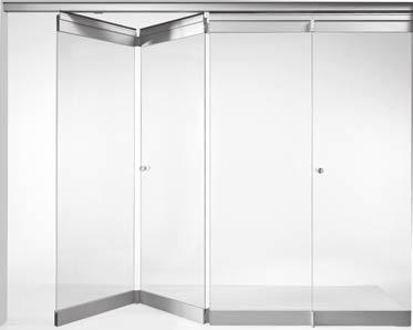
3 HORIZONTAL SLIDING WALLS HSW TRANSPARENT VERSATILITY Horizontal sliding walls are used in a wide range of different project types, and for both internal and external applications. These partitions can be flexibly designed to suit the site of installation, structural conditions and design concept. They can satisfy a broad spectrum of requirements in relation to styling, material and finish or colour, and can also be equipped with individually fabricated panels to perform special functions. Additional utilisation of the DORMA substructure ensures flexible planning in the case of all system variants as well as providing for the simple installation, maximum reliability and outstanding safety of the entire system. HSW - Horizontal Sliding Walls Panels slide individually stacking track required HSW-G Fully glazed with door rails HSW-MR Panel types and functions HSW-GP Single-point fixings with standard track rail HSW Horizontal Sliding Walls, fully framed Panels slide individually stacking track required HSW-R Fully framed for toughened safety glass, laminated safety glass or double glazing HSW-ISO Fully framed with thermal-break frame profiles FSW Folding Sliding Walls Panels slide individually stacking track required FSW-G FSW-G Fully glazed with door rails FSW-C FSW-C Roller carrier position at door rail centre FSW-C plus Roller carrier position at door rail centre plus full-width sliding folding panel FSW-C plus 2 DORMA


4 HORIZONTAL SLIDING WALLS CONTENT HSW Support and Guide Elements Parking And Stacking Example Stacking Arrangements Stacking Arrangement Calculations Track Rails Substructure HSW / FSW Panel Systems HSW-G HSW-MR HSW-GP FSW-G FSW-C/C Plus HSW-R HSW-ISO Accessories Vertical Seals Overview Vertical Sealing Profiles Floor Track General Information Measuring Up General Information Subject to change without notice DORMA 3


5 SUPPORT AND GUIDE ELEMENTS STACKING SYSTEMS Perfect parking every time Existing structures or unusual layouts often require special solutions, particularly in the design of the stacking area. DORMA HSW systems can be parked in a range of different positions. The stack of panels can be aligned parallel or square to the frontage, be readily visible for effect or hidden behind columns etc. Another possibility is that of parking the system in line but out of the way, whether behind a wall or in a niche (see also pages 5 9). The panels can also perform certain functions when the frontage is open, such as providing the sides of internal store windows and showcases, or, if provided with the appropriate printing on the glass, for adding artistic value to a wall. The following pages show some system solutions devised in answer to a wide range of different problems. 4 DORMA
6 EXAMPLE STACKING ARRANGEMENTS Panels stacked 90 transverse to travel direction Standard stacking arrangement. With pivoting end panel as possible access leaf (left or right, or left and right). Stacking in a box/pocket. Sliding panels or double action panels only (left or right, or left and right). Niche parking. With pivoting end panel as possible access leaf (left or right, or left and right). Stacking with reshuffle bypass (without pivoting end panel). Behind wall projection/fixed side panel (Left or right, or left and right). Not for HSW-MR. Stacking track 135 behind column. With end panel as possible access leaf (left or right, or left and right). Stacking behind end panel. (Left or right, or left and right). Stacking at acute angle. All panels brought into position with rear track roller. Stacking in a box or niche, behind end panel. Sliding panels only, around 135 offset (left or right, or left and right). DORMA 5
7 SUPPORT AND GUIDE ELEMENTS PANELS PARALLEL TO TRAVEL DIRECTION Stacking track at 5 angle for small number of panels (up to 6) (left or right, or left and right). Stacking track offset in niche with folding panel as wall connection (left or right, or left and right). X Stacking track 135 (left or right, or left and right). Detail X Sliding panel with final folding panel in closed wall. Max. system height 3 m Sliding panel with final folding panel ready for sliding into stacking track. Max. system height 3 m Parallel stacking track for large number of panels (left or right, or left and right). Parking behind fixed panels (left or right, or left and right). Fixed panels Sliding panel 1 Stacking track 90 behind column with pivoting end panel as possible access leaf (left or right, or left and right). Stacking track beyond offset pivoting end panel (left or right, or left and right). Closed system 6 DORMA
8 EXAMPLE STACKING ARRANGEMENTS SPECIAL STACKING ARRANGEMENTS Stacking at the wall in closed compartment behind pivoting end panel Stacking at the wall in closed compartment without pivoting end panel Stacking in front of 90 wall with 90 angle section without closing pivoting end panel Stacking panels of varying width Closed wall Stacking without stacking track with 4 panels (2 pivoting end panels / 2 sliding panels) DORMA 7
9 SUPPORT AND GUIDE ELEMENTS STACKING ARRANGEMENT CALCULATIONS Straight track rail with stacking position transverse to travel direction T1 T2 = T a b b b a b = depending on pull handle depth or 75 mm where profile cylinder provided at front-mounted slide bolt = 65 mm for HSW-G 80 mm for HSW-R 90 mm for HSW-ISO Width of stacking track B1 = Panel width 120 mm (0.087 x T1) B2 = B1 192 * HSW-GP cannot be provided with a 95 branch 95 * 92 T3 = T4 92 T4 = T1 Straight track rail with stacking track parallel to direction of travel (135 ) a b = depending on pull handle depth = 65 mm for HSW-G 80 mm for HSW-R and HSW-GP 90 mm for HSW-ISO B B2 = B B1 = Panel width 130 mm T1 = T3 x mm T3 b b b b a T1 T2 = T DORMA
10 5 HSW / FSW STACKING ARRANGEMENT CALCULATIONS Straight track rail with stacking position parallel to travel direction (90 ) with up to approx. 10 panels B1 36 B2 = B * a b = depending on pull handle depth or 75 mm where profile cylinder provided at front-mounted slide bolt = 65 mm for HSW-G 80 mm for HSW-R 90 mm for HSW-ISO 80 T2 = T b b b a 130 b T1 * HSW-GP cannot be provided with a 95 branch B1 = Panel width 130 mm ([T1 80] x 0.087) Straight track rail with stacking position parallel to travel direction (90 ) with more than 10 panels B B2 = B b b b b a T2 = T T1 a b = depending on pull handle depth or 75 mm where profile cylinder provided at front-mounted slide bolt = 65 mm for HSW-G 80 mm for HSW-R and HSW-GP 90 mm for HSW-ISO B1 = Panel width 130 mm 80 b b DORMA 9
11 10 DORMA HSW SUPPORT AND GUIDE ELEMENTS Track Rails Substructure 14 19
12 DORMA 11
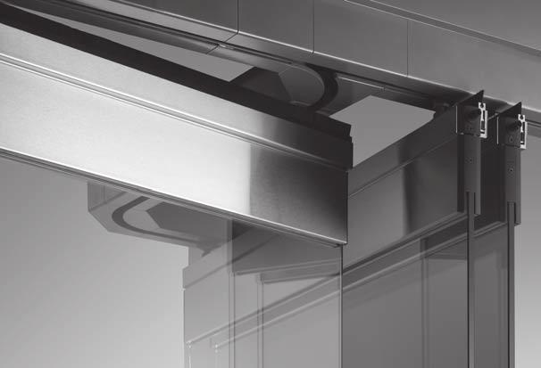
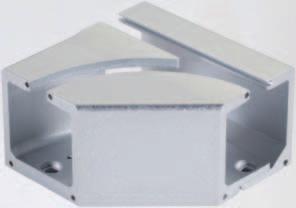
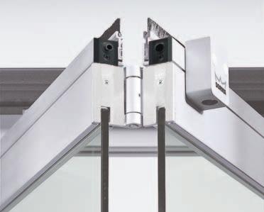
13 SUPPORT AND GUIDE ELEMENTS TRACK RAILS AND MODULES Flexible and stable Horizontal sliding walls can be constructed in a wide range of different configurations to suit the site of installation, prevailing structural conditions and the planning concept. With DORMA HSW systems, a variety of designs can be implemented with ease. Straight, segmented and curved track rails can be combined to produce virtually any serpentine shape required. The track rails in the form of hollow sections combine all the virtues of light weight, stability and torsional stiffness. And when combined with the HSW substructure, installation becomes even easier. Flexibility and stability mean that even unusual system configurations can be implemented without problem to give maximum functional reliability. Straight track rail 90 T-piece Stacking track rail l 9 Track rail at closed wall position l Straight track rail For a straight-line system configuration, a drill hole interval of 300 mm in the track rail is sufficient, while the stacking area requires an interval of 150 mm. Where the track assumes an angle of , the track rail is mitred, while at angles between 90 and 160, a segment is incorporated. The standard modules available are indicated in the adjacent illustrations. 135 T-piece Left or right l 9 90 L-piece l Modul 07/09 for 90 /95 angle Modul 06 for 45 angle 90 angle left/right / DORMA
14 TRACK RAILS Segmented track rail With the segmented track rail, it is possible to implement the DORMA HSW as a polygonal partition or frontage. In so doing, it is essential to note the following requirements:. the panel width and segment chord length must be properly coordinated;. segment panels are provided at the bottom with locks or face-mounted floor bolts and the end cap are equipped with additional buffers for collision protection;. it is important to ensure that the opening sweep of single action and double action panels does not give rise to collisions. Curved track rail A curved track rail is also available where a curved DORMA HSW system configuration is required. The most important technical prerequisites for this are as follows: l 9 1 Rmin of the neutral fibre = 3500 mm 72 Curved track rail, bolted double shell construction Countersunk screw DIN 7991 M6x10. A2 75. only non-pivoting sliding panels may be installed in the curved track rail section;. the track rail must be straight in the parking or stacking area;. no top locking element can be installed;. each panel is provided with two face-mounted floor bolts;. a 100 mm straight track section (1) is necessary as the transition from the curved track rail to the straight stacking track rail;. blends from the curved configuration to a straight line can be implemented using standard modules (2);. the smallest curve radius is 3,500 mm (smaller radii on application) (3);. the feasibility of elliptic system configurations must be considered on a case-bycase basis for this, drawings will be necessary;. the start and end points of the curve are always provided with a 90 saw cut (radial saw cut). DORMA 13
15 SUPPORT AND GUIDE ELEMENTS SUBSTRUCTURE - THE SYSTEM Solutions Installing a horizontal sliding wall system invariably requires a certain set of structural conditions to be established. The system will need to be precisely aligned vertically usually sub-sequent to installation as well as being exactly configured and securely located. Because DORMA HSW systems do not use floor-level supports and floor tracks, the system requirements and all their technical properties must be taken into account when designing the substructure and its incorporation within the ceiling. This often very costly planning process is normally undertaken by the fabricator as the installation company, and alongside the calculations there are many individual structural and installation procedures involved. The new DORMA substructure system is of modular construction and is designed to significantly reduce on-site installation cost and time. This concept also offers the particular flexibility required to overcome structural constraints, such as the presence of air conditioning shafts or pre-existing electrical systems in the ceiling. Milled U recess M10 threaded rod Fixing plate Pivoting angle bracket Lateral bolting channel Standard square section tubes Pivot fixing Substructure profile Upper bolting channel Centre channel System design The DORMA substructure consists primarily of the following components: substructure profile with modules for branching to the stacking area, threaded rods for suspension of the profile(s), and standard square section tubes with appropriate fixings and ceiling brackets for bracing and stiffening the construction. 14 DORMA
16 SUBSTRUCTURE The forces (shown by arrows) that occur during opening and closing of the sliding wall system must be absorbed by appropriately located bracing elements. Safety and flexibility The DORMA substructure has been developed on the basis of extensive practical experience of the requirements involved in this kind of system. Consequently, the profile incorporates features that greatly facilitate installation and ensure that pre-existing structural factors can be accommodated with maximum flexibility. Various bolting channels run the whole length of the profile, allowing bolts to be inserted easily at any location within the system configuration. So there is no need for pre-drilling and thread cutting in order to mount the track rails onto the substructure. Bolted connections can be made directly through the lower bolting channel. The problem of removing drillings and filings from the track rails is thus also a thing of the past. Bolting channels on both sides of the profile can be used e.g. for fixing the brackets needed for attaching the ceiling retention elements. In addition, centering grooves on all main profile surfaces facilitate overhead drilling, e.g. for accessory attachment. Welding brackets designed for bolting onto the profile provide another option, allowing the DORMA system to be utilised for additional customer-specific applications. The substructure profile is suspended from threaded rods. These are first placed in the U-recesses using fixing plates that lock into the upper bolting channel. Each pair of threaded rods is regarded as constituting one suspension point. Here again the system remains exceptionally flexible: the staggered U-recesses positioned at intervals of 100 mm enhance the ability of the system to accommodate structural constraints. Depending on the weight of the system and the permitted deflection, it is possible to span a distance of up to 2,100 mm between two suspension points. The centre channel can be fitted with two flat aluminium bars to provide additional rigidity in the area of butt joints between profiles In this case it is possible to dispense with the dual suspension arrangement with one suspension point either side of the joint which is otherwise necessary. So existing building installations of all types can be effectively bypassed. Once the substructure has been installed, the HSW system is vertically aligned and fixed directly via the threaded rods. Subsequent adjustments, e.g. after the building has settled into its foundations, can also be carried out by the same means. The standard square section tubes offer extra safety, especially where the sliding panels deviate from a straight line. Panel sway must be effectively countered by the structural design adopted at such locations. Diagonal struts that counteract the pressure load stabilise the system in the area of the stacked panels. The telescopic square section tubes are connected as additional bracing elements (struts) to the substructure by a pivot fixing. The struts are bolted to the ceiling using the appropriate angle brackets. The modular design of the DORMA substructure is precisely matched to the modules of the DORMA HSW track rail. The structural elements can be mixed and matched as desired with the result that a small number of component types is sufficient to create a complex, flexible system that conforms fully to all safety requirements. A drawing of the required substructure can be requested from DORMA to supplement the HSW system drawing always supplied with the quotation. DORMA 15
17 SUPPORT AND GUIDE ELEMENTS PLANNING DETAILS Calculating the suspension intervals Max. 2 mm deflection between two suspension points With a maximum load (panel weight) of 150 kg/m and a permitted deflection of the substructure with track rail of 2 mm, the interval between two suspension points must be no greater than 1450 mm. The table below shows other values for different loads mm In order to prevent system sway, every second suspension point must be reinforced by a strut. The substructure profile ends (travel path and stacking area) should ideally be directly connected to the masonry or to existing structural members. Illustrative example of load values Table for the calculation of the max. distance dimension Front AM Parking area F HSW-G characteristic values Formula for calculating the: Glazing height = system height 309 mm = panel height 193 mm Glazing weight Glass 10 mm = kg/m 2 Glass 12 mm = kg/m 2 Door rail weight Aluminium = kg/m Brass = kg/m Stainl. steel = kg/m Distance dimension max. depending on carrying function F AM 60 kg/m 2,050 mm 75 kg/m 1,900 mm 90 kg/m 1,750 mm 105 kg/m 1,750 mm 120 kg/m 1,600 mm 135 kg/m 1,600 mm 150 kg/m 1,450 mm 160 kg/m 1,450 mm F = Force AM = Distance dimension Force example: The distance dimension of 108,98 kg/m = 1,710 mm (can be linearly interpolated) Example system HSW-G system in stainless steel System height 3,500 mm Glazing thickness 12 mm Calculation Load = glazing weight x glazing height + door track weight = 30 kg/m2 2 x (3,500 mm 309 mm) kg/m = 30 kg/m 2 x 3,191 mm kg/m = kg/m 16 DORMA
18 SUBSTRUCTURE STACKING AREA DESIGN View from below The construction of the stacking area, assembled from substructure and track rail modules, provides a good illustration of how this well-designed system can be utilised. The individual components are coordinated to ensure safe integration. Joints in the substructure are offset to those in the track rails so that individual joints coincide with continuous material in all cases. Provided that the track rails are adequately bolted to the substructure, gaps of up to 40 cm measured from one suspension point to the next are permitted in the substructure. View from below Substructure Track rail Detachable section 90 branch module 95 branch module Strut View from above Joints reinforced by central steel bar only require one local suspension point. 1 suspension point = 2 threaded rods L-piece for 95 branch Strut Joint area reinforced using flat steel bars inserted in the centre channel 90 T-piece Suspension points either side of joints not reinforced by central steel bar DORMA 17
19 SUPPORT AND GUIDE ELEMENTS VARIANTS OF CONNECTION / DETAILS UK-Profile Profile connection with connection lug Art. No Wall connection with angeled connection lugs. Bending of connection lug on site according to need Art. No Direct connection to ceiling Welding connection to steel girder Connection opportunities to existing bearing structure like ceilings, balks, steel girder by dint of adapter plate Art. No Flexible connection to ceiling Connection to steel construction 18 DORMA
20 SUBSTRUCTURE COMPONENT PARTS, ACCESSORIES Component parts D 1 E 1 Pivoting angle bracket Art. No Fixing plate Art. No Pivot fixing Art. No Adapter plate Art. No Basic substructure profile, stock length 6000 mm Art. No Fixed length Art. No A F DIN and standard parts by others or on request CSN = Company standard no. B 2 I C B 5 K 3 J 4 H G Adapter plate for neutral connection G L A Threaded rod M10 x 1,000 CSN B Hex nut DIN M10 CSN C Washer ISO CSN D Hex nut DIN 934-M6 CSN E Hex socket screw DIN 933-M6x35 CSN F Telescopic strut top section, square section tube, galvanised steel 20x20x2 CSN G Drilling screw DIN 7504 ST4 8x16 CSN H Telescopic strut bottom section, square section tube, galvanised steel 25x25x2 CSN I Hex nut DIN 934-M6 CSN J Hex socket screw DIN 933-M6x40 CSN K Self-tapping screw ISO 7049-St4.8 x 13-C-H CSN L Cylinder head screw for fixing track rail to substructure profile DIN 912-M8x25 CSN Stock length 6000 mm A DORMA 19
21 20 DORMA HSW / FSW PANEL SYSTEM HSW-G 22 34

22 DORMA 21
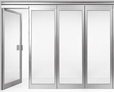
23 PANEL SYSTEM PANEL TYPES In the case of the fully glazed HSW-G / HSW-MR systems, the panels create a continuous, transparent surface without any lateral framing. For a more sophisticated or intricate appearance, single-point fixings (HSW-GP) are also available. HSW-G / HSW-MR / FSW-G / FSW-C/C plus Fully glazed with door rails HSW-GP Fully glazed with single-point fixings This folding system with top and bottom glazing rails coordinates perfectly with the HSW-G variant. The FSW-G operates without a separate stacking area, and instead folds together within the main frontage or partition zone. 22 DORMA
24 HSW-G HSW-R Fully framed HSW-ISO Fully framed with double glazing The all-round framing provided on the individual panels of an HSW-R system not only offers high stability but also an excellent barrier to keep out external influences. The panels can be constructed with laminated or toughened safety glass as required. DORMA 23
25 PANEL SYSTEM PANEL TYPES AND FUNCTIONS Horizontal sliding walls Fully glazed with glazing rails (100 mm) top and bottom Within an HSW-G system, the individual panels can be designed to perform certain special functions. These range from simple sliding panels to integrated doors with a variety of door closers, or special panels for unusual installation situations. And each system can be assembled to suit individual requirements. The standard glass thickness is 10 or 12 mm. Further glass thicknesses on request. Max. panel sizes and weights Single action / double action end panel Non-sliding. Single action panel with floor pivot and TS 92 / TS 73 door closer. Double action panel with floor pivot or BTS floor spring. Sliding panel Fixed when frontage closed. Single action sliding panel Single action sliding panel with TS 92 cam-action door closer, operational when frontage closed. Alternatively with ITS 96 1). Double action sliding panel * With RTS transom door closer, operational when frontage closed. Alternatively with ITS 96 2). Double action sliding panel * With RTS transom door closer, operational when frontage closed. Alternatively with ITS 96 2). Max. system height 4,000 mm 4,000 mm 3,600 mm 3,600 mm 3,600 mm Max. panel width 1,250 mm 1,250 mm 1,250 mm 1) 1,100 mm 1,250 mm 2) 1,100 mm 1,250 mm 2) 1,100 mm Max. panel weight 150 kg 150 kg 100 kg** 100 kg** 100 kg** The individual panels can also be of differing widths. The largest width should not exceed max. 115% of the smallest width. * For these panel types please consider our notes on portal systems on page 101. ** Note: The maximum permissible weight relates to the complete door assembly, including handles. 24 DORMA
26 HSW-G SYSTEM DESIGN Bottom door rail designs All depicted combinations are also available as mirror arrangements End-mounted pin bolt at wall End-mounted pin bolt at wall End-mounted pin bolt at wall Recess for end-mounted slide bolt End-mounted slide bolt Face-mounted slide bolt Deadlock Face-mounted slide bolt 2, ± Irrespective of the function of the individual panels, an HSW-G system comprises the following basic components: 1 Installation-efficient DORMA substructure to accommodate track rail mounting requirements (optional) 2 Track rail for bolting to the substructure. 3 Carrier 4 Suspension assembly and 5 bearing profile for safe and easy sliding of the panels. 6 Top door rail and 7 bottom door rail, both comprising base profiles with clip-on face and side covers. 8 Toughened safety glass (by others). Toughened laminated safety glass on request. Recess for end-mounted slide bolt End-mounted slide bolt 25 8 Recess for end-mounted slide bolt Deadlock 32 Deadlock End-mounted slide bolt Face-mounted slide bolt End-mounted slide bolt Face-mounted slide bolt Face-mounted slide bolt Floor surface Face-mounted slide bolt Deadlock DORMA 25
27 PANEL SYSTEM FIXED PANEL Double action or single action end panel with floor pivot Non-moving and always equipped with a bottom deadbolt with the option of a top bolt or sideaction deadlock. Can be designed as a double action or single action leaf. Double action end panel Assembly types:. Floor pivot with round spindle. BTS 84 for panels up to 100 kg, with optional holdopen at 90 door opening angle. BTS 80 for panels up to 150 kg with adjustable hold-open device Glazing height = Total height 308 mm ± ,5 2, End cover 36,5 27 Pivot bearing door rail insert (for BTS as well) Single action end panel with stop-type covers top and bottom. Assembly types:. Floor pivot with round spindle. As above, but with DORMA TS 73 or TS 92 overhead door closer. BTS 84 for panels up to 100 kg, with optional holdopen at 90 door opening angle. BTS 80 for panels up to 150 kg with adjustable holdopen device Double action end panel with floor spring bottom strap in forged steel Mounting dimensions BTS 84 BTS 80 a b b a d c c d DORMA
28 HSW-G Single action end panel with TS 73 overhead door closer and additional locking device , Single action end panel with TS 92 overhead door closer and additional locking device max , min. panel width 870 mm Additional locking device 7 6 Data and features TS 73 V TS 92 Closing strength/size EN 2 4 EN 2 4 Closing strength, variable via adjusting screw and arm hinge via adjusting screw and arm hinge Closing speed adjustment via valve via valve Non-handed x x Latching speed adjustment via arm via arm Cushioned stay limit adjustment Hold-open adjustment Weight 1.8 kg 1.9 kg Length 233 mm 281 mm Overall depth mm 47 mm Height 60 mm 65 mm DORMA 27
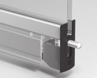
29 PANEL SYSTEM SLIDING PANEL Track roller , ± End cover Stationary when the frontage or partition is closed. Sliding panel The sliding panels are the moving elements. Once in their closed position, they are locked down. The components available for this are provided in the bottom door rail in the form of face-mounted slide bolts, end-mounted slide bolts, end pin bolts or deadlocks. Glazing height = Total height 308 mm Sliding panel 4 Sliding panel End-mounted slide bolt Turn grub screw to adjust locking pin Eccentric bushing Bottom door rail Panel width Base profile with integral functional element (here: face-mounted slide bolt) Base profile with functional element (here: deadlock) 28 DORMA
30 PANEL TYPES HSW-G SINGLE ACTION SLIDING PANEL 75 Track roller ± TS 92 Sliding panel Pivot bearing Single action sliding panel Swing panel with TS 92 camaction door closer for operation as a single action door when the frontage is closed. With DORMA TS 92 cam-action door closer This panel type is installed where doors only need to be opened in one direction. The pivoting sliding panels can be fitted open inwardly or outwardly. In both cases, the cam-action door closer is fixed to the inside face. Glazing height = Total height 308 mm Face-mounted slide bolt Eccentric bushing Standard assembly top: Pivot bearing, TS 92 with slide channel, one locking device bottom: Face-mounted slide bolt as pivot (released for sliding function) and lock Locking device Optional equipment top: Second locking device (for reshuffle bypass) bottom: Optional second facemounted slide bolt instead of deadlock M6 l 7 l 10 max Top pivot DORMA 29
31 PANEL SYSTEM DOUBLE ACTION SLIDING PANEL Max. Sliding panel weight 100 kg Track roller Pivoting panel with RTS transom door closer for operation as a double action door when the frontage is closed. With integral DORMA RTS transom door closer Double action sliding panels with DORMA RTS transom door closers (patented design) are characterised by their exceptional ease of installation and operation; an excellent alternative to the solution with the BTS floor spring because the RTS does not require a large recess in the floor. These panels are generally equipped with a bottom deadlock and top locking device plus a bottom facemounted slide bolt operating as the pivot bearing (released for the sliding function). The standard solution takes the form of the RTS 85 without hold-open, or as a special option, with a 90 hold-open. For these panel types please consider our notes on portal systems on page Glazing height = Total height 312 mm Locking device RTS l 7 M ± Sliding panel RTS 85 RTS insert Double action sliding panel Face-mounted slide bolt Eccentric bushing 73 l 7 max , Top pivot 30 DORMA
32 HSW-G FIXED PANEL Position 90 and 180 opening angle at wall, position 180 opening angle at fixed panel Top centre upper part ± ,5 21 Top centre lower part 100 End cover opening angle Offset pivoting end panel at fixed panel Max. panel weight 100 kg Offset hung end panel Single action panel, non-sliding, operates independently of the rest of the system. The single action door with offset pivoting arm assembly can be swung around 180, so leaving the entire operating zone free. A bottom deadlock secures the closed leaf. Bottom door arm Pivoting end panel views as seen from below 75 Fixed panel fixing arrangement 65 2, ±5 Glazing height = Total height 308 mm Fixed side panel Non-moving side panel, independent of the rest of the system. The fixed side panel is of the same basic design as the sliding panels. And if required, the fixings can be replaced by a carrier system to convert such a panel into a sliding panel Sliding panel 4 Fixed panel End cover End-mounted slide bolt with fixed pin DORMA 31
33 PANEL SYSTEM FOLDING SLIDING PANEL Magnetic door holder Panel hinge Roller carrier Magnetic door holder End-mounted slide bolt and panel hinge ± Magnetic door holders top and bottom Hinged, with lock and slide bolt at the bottom, latching bolts top and bottom for fixing the final folding panel to the slide panel. FSW-C 42 FSW-C plus Max. panel sizes and weights Max. panel width 2 x 1,000 mm Max. system height 3,000 mm Max. panel weight 2 x 70 kg End mounted slide bolt Panel hinge DORMA
34 PANEL TYPES HSW-G SLIDING PANEL WITH ITS Max. panel weight 100 kg 75 Rollercarrier Sliding track ±5 Single action sliding panel with integral door closer ITS 96 Gr. 2 4 This panel variant is used where the door element is required to only open in one direction. Single action sliding panels can be either inward or outward opening. Glazing height = Total height 308 mm Single action sliding panel 4 65 Pivot point Front mounted slide bolt Eccentric bushing Standard equipment pivot at the top, ITS 96 with slide channel, 1 locking device at the bottom in the form of a face-mounted slide bolt (released in sliding mode) and deadbolt lock. M Optional equipment top 2 nd locking device (to facilitate disengaging); bottom: 2 nd facemounted slide bolt instead of deadbolt lock. l 7 max l 7 15 Single action sliding panel inward opening Stop Sliding panel Data and features: ITS 96 Gr. 2 4 Closing strength / size EN 2 4 Max. opening angle ca. 120 Max. panel width 1,100 mm Hold-open variable yes Max. panel height 100 kg Weight 1.3 kg Closing strenght continuously variable Adjusting screw Length 277 mm Closing speed continuously variable Valve Overall depth 32 mm Same design for DIN-L and DIN-R yes Height 42 mm Latching speed continuously variable yes Door closer tested according to EN 1154 yes Cushioned stay limit mechanically variable yes DORMA 33
35 PANEL SYSTEM DOUBLE ACTION SLIDING PANEL WITH INTEGRAL DOOR CLOSER Roller carrier Sliding track Double action sliding panel with integral DORMA door closer Double action sliding panels with DORMA ITS 96 Gr. 2 4 offer exceptional ease of installation and operation, making them a good alternative to the variant with the BTS floors spring particularly as the ITS 96 does not need a large recess in the floor. Being virtually invisible, its presence has no effect on the overall appearance of the partition. These panels come equipped as standard with a bottom deadbolt lock and a locking device at the tope, together with a face-mounted slide bolt as the bottom pivot point (released in the sliding mode). In its standard form, ITS 96 is provided with a 90 hold-open. If you care considering this panel type, please note our advisories relating to portal systems on page M ±5 Glazing height = Total height 308 mm l 7 l max Double action sliding panel Pivot point front mounted slide bolt Eccentric bushing Data and features: ITS 96 Gr. 2 4 Closing strength / size EN 2 4 Max. opening angle ca. 120 Max. panel width 1,100 mm Hold-open variable yes Max. panel height 100 kg Weight 1.3 kg Closing strenght continuously variable Adjusting screw Length 277 mm Closing speed continuously variable Valve Overall depth 32 mm Same design for DIN-L and DIN-R yes Height 42 mm Latching speed continuously variable yes Door closer tested according to EN 1154 yes Cushioned stay limit mechanically variable yes 34 DORMA
36 HSW-G DORMA 35
37 36 DORMA HSW / FSW PANEL SYSTEMS HSW-MR 38-42
38 DORMA 37
39 PANEL SYSTEM TYPES AND FUNCTIONS Horizontal sliding walls Fully glazed with glazing rails (75 mm high) top and bottom. Designed to meet the minimum essential requirements of a shopfront, the HSW-MR constitutes a cost-efficient alternative to the classic HSW-G. The HSW-MR assemblies are available for 10 or 12 mm glass thickness. Double action / single action end panel Non-sliding. Doubel action end panel with floor bearing and top pivot. Optional with floor spring BTS 80 / 84. Or as single action end panel with stop and BTS 80 / 84 or TS 92 / TS 73. Sliding panel Fixed when frontage closed. Sliding panel Fixed when frontage closed. Fixed panel Non-sliding. Fixed side panel with retaining pins at the top and door rail with bottom spacer profile at the bottom. Max. panel sizes and weights Max. system height 3,000 mm 3,000 mm 3,000 mm 3,000 mm Max. panel width 1,250 mm 1,250 mm 1,250 mm 1,250 mm Max. panel weight 100 kg 100 kg 100 kg 100 kg 38 DORMA
40 HSW-MR SYSTEM DESIGN Bottom door rail designs All depicted combinations are also available as mirror arrangements 72 Irrespective of the function of the individual panels, an HSW-MR system comprises the following basic components: End-mounted pin bolt at wall End-mounted pin bolt at wall Recess for end-mounted slide bolt Recess for end-mounted slide bolt Deadlock End-mounted slide bolt Deadlock End-mounted slide bolt Deadlock End-mounted slide bolt ± Installation-efficient DORMA substructure to accommodate track rail mounting requirements (optional). 2 Track rail for bolting to the substructure. 3 Carrier 4 Suspension assembly and 5 bearing profile for safe and easy sliding of the panels. 6 Top door rail and 7 bottom door rail, both comprising base profiles with velcro technique and side covers. 8 Toughened safety glass or toughened laminated safety glass (by others) 10 / 12 mm. DORMA 39
41 HSW / FSW PANEL SYSTEM FIXED PANEL Double action or single action end panel with floor pivot Non-moving and always equipped with a bottom deadbolt with the option of a top bolt or sideaction deadlock. Can be designed as a double action or single action leaf. Total height Glazing height = Total height 265 mm Double action end panel Assembly types:. Floor pivot with round spindle. BTS 80 / 84 for panels up to 100 kg, with optional holdopen at 90 door opening angle 75 7 Single action end panel with stop top or stop-type covers top and bottom. Assembly types:. Floor pivot with round spindle. BTS 80 / 84 for panels up to 100 kg, with optional holdopen at 90 door opening angle Double action end panel with floor spring , The choice of door closer will depend on the installation situation in each case Mounting dimensions BTS 84 BTS 80 a b c b a d c d DORMA
42 HSW-MR SLIDING PANEL Sliding panel Stationary when the frontage or partition is closed. The sliding panels are the moving elements. Once in their closed position, they are locked down. The components available for this are provided in the bottom door rail in the form of end-mounted slide bolts, end pin bolts or deadlocks. Total height 19 Glazing height = Total height 265 mm 7 Bottom door rail Panel width Base profile with integral functional element (here: end-mounted slide bolt) Base profile with functional element (here: deadlock) DORMA 41
43 PANEL SYSTEM FIXED PANEL ± Fixed side panel Non-moving side panel, independent of the rest of the system. The fixed side panel is of the same basic design as the sliding panels. And if required, the fixings can be replaced by a carrier system to convert such a panel into a sliding panel. Glazing height = Total height 265 mm 42 DORMA
44 HSW-MR DORMA 43
45 44 DORMA HSW / FSW PANEL SYSTEMS HSW-GP 46-49
46 DORMA 45
47 PANEL SYSTEM HSW-GP PANELS AND FUNCTIONS Fully glazed sliding walls with point-fixed track roller carriers engaging in standard track rail. The characteristic features of HSW-GP systems are the singlepoint fixings of the glass panels in combination with a conventional track rail profile. The design, featuring a high-grade stainless steel finish and the distinctive flush-mounted or clamping disc attachments, coordinates perfectly with contemporary architecture. Even curved glazing can be securely held by this system. And this can also be combined with curved track rail profiles to produce unique configurations. The standard glass thickness is 10/12 mm. Further glass thicknesses on request. Max. panel sizes and weights Double / single action end panel Non-sliding. With full-length pivot rod and offset pivot. Single action panel with floor pivot, round spindle and stop. Double action panel with floor pivot or BTS floor spring. Sliding panel Fixed when frontage closed. Double / single action end panel Non-sliding. With centre pivot top and bottom. Single action panel with floor pivot, round spindle and stop. Double action panel with floor pivot. Fixed panel Non-sliding. Fixed side panel with retaining pins at the top and fixed panel straps at the bottom. Max. system height 3,000 mm 3,000 mm 3,000 mm 3,000 mm Max. panel width 1,200 mm 1,200 mm 1,200 mm 1,200 mm Max. panel weight 100 kg 100 kg 100 kg 100 kg The position of the track is not adjustable. The width of all panels must be uniform. 46 DORMA
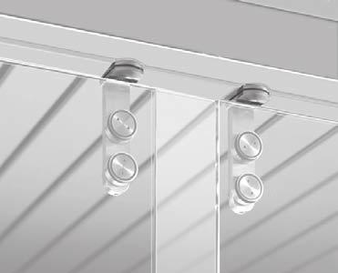
48 HSW-GP SYSTEM DESIGN Sliding panel with bottom end-mounted pin Sliding panel with bottom face-mounted slide bolt The HSW-GP system consists of the following basic components: installation-efficient DORMA substructure to accommodate track rail mounting requirements (optional). 2 track rail for bolting to the substructure. 3 roller, 4 suspension assembly, 5 strap with single-point fixings, 6 toughened safety glass or toughened laminated safety glass (by others), 7 bottom strap with end-mounted pin, 8 bottom strap with face-mounted slide bolt. Inside 11 Inside Glazing height = Total height 126 mm Total height 15,5 8, Glazing height = Total height 126 mm Total height Floor surface 7 7 DORMA 47
49 PANEL SYSTEM TYPES AND GLASS DRILLING REQUIREMENTS Double / single action end panel with pivot rod Glass drilling pattern Glazing width 7 Pivot pin Pivot rod, short type with singlepoint fixings Pull handle with single-point fixings/ Back-to-back pull handles Pivot rod connecting tube Pivot rod, short type with singlepoint fixings Deadlock Bottom bearing bush Length of connecting tube = Glazing height 535 mm 8 Glass bore centres for pull handle/back-to-back pull handles 1560 ± 0, ± 0,3 520 ± 0,3 min. 65 mm Countersunk bores Countersunk bores l 55 for deadlock Glazing height = Total height 126 mm Double / single action end panel Glass drilling pattern Glazing width Strap with singlepoint fixings Glass bore centres for pull handle/back-to-back pull handles Countersunk bores Pull handle/back-toback pull handles Deadlock Pivot strap with floor pivot ± 0, ± 0,3 520 ± 0,3 min. 65 mm 65 Countersunk bores 65 l 55 for deadlock Visible corner notch 55 Glazing height = Total height 126 mm 48 DORMA
50 HSW-GP Sliding panel Fixed panel Glass drilling pattern Glazing width Straps with single-point fixings Straps with single-point fixings Countersunk bores 55 Bottom strap with face-mounted slide bolt Fixed panel strap Glazing height = Total height 126 mm Bottom strap Fixed panel strap Countersunk bores Visible corner notches Glass bores and notches Countersunk bores for single-point fixings for the pull handles and straps l 26 10/12 l 32+0,2 90 Bores for clamping disc single-point fixings l 26 Bores for pull handle pairs l 22 Bores for locks l 55 Visible corner notches, bottom /12 10/12 R10 R10 3-0,2 10/12 Special stop Pivot rods (short type) with singlepoint fixings and connecting tube Pull handle with single-point fixings ± ± 15 Bottom pivot for pivot rods Back-to-back pull handles DORMA 49
51 PANEL SYSTEMS FSW-G DORMA
52 DORMA 51
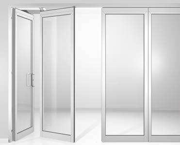
53 PANEL SYSTEM TYPES AND FUNCTIONS FSW folding sliding walls as fully glazed partitions and frontages, with door rails top and bottom, track roller position at the end of every second panel. Folding sliding walls are ideal for a straight-line system configuration. In an FSW-G partition, there are either 2 or 4 interlinked panels (1 base panel and 1 or 3 folding panels). With double assemblies moving counter to each other (bi-parting), therefore, it is possible to create frontages comprising up to 8 FSW panels. As the panels of an FSW system are visually compatible with those of the HSW-G line and both systems use the same track construction, the two can be ideally combined as a single shopfront or transparent partition, with the FSW system mating at its free end with a free HSW single-action or double-action access panel (types 4 + 5). For assembly types see pages Example: assembly with 2 x 2 panels (type 1c) moving counter to each other 1 Track rail 2 Folding panel 3 Folding hinge 4 Roller 5 FSW base panel 6 Top locking device 7 Bottom locking device Base panel with top pivot and bottom floor pivot. Folding panel with carrier and locking device top Folding panel with carrier and locking device top Folding panel with carrier and locking device top Max. panel sizes and weights and bottom. and bottom. and bottom. Max. system height 3,000 mm 3,000 mm 3,000 mm 3,000 mm Max. panel width 1,000 mm 1,000 mm 1,000 mm 1,000 mm Max. panel weight 70 kg 70 kg 70 kg 70 kg The standard glass thickness is 10/12 mm. Further glass thicknesses on request. 52 DORMA
54 FSW-G SYSTEM DESIGN Base panel Folding panel 72 The FSW-G system consists of the following basic components: ± ,5 Floor surface 1 installation-efficient DORMA substructure to accommodate track rail mounting requirements (optional). 2 track rail for bolting to the substructure. 3 top pivot, 4 roller, 5 top locking device, 6 suspension assembly and 7 carrier profile for safe and easy sliding of the panels. 8 folding hinge, 9 top door rail and 10 bottom door rail, both comprising base profiles with clip-on face and side covers. 11 toughened safety glass or toughened laminated safety glass (by others), 12 floor pivot, 13 face-mounted slide bolt ,5 Door rails cut to size 4,5 5 DORMA 53
55 PANEL SYSTEM ASSEMBLY TYPES Type 1 Type 1a 2 panels left, as drawn Type 1b 2 panels right, mirror arrangement Type 1c 4 panels (2 panels left and 2 panels right), bi-parting Type 2 Type 2a 4 panels left, as drawn Type 2b 4 panels right, mirror arrangement Type 2c 8 panels (4 panels left and 4 panels right), bi-parting min. 120 mm Type 3 Type 3a 6 panels as drawn (4 panels left and 2 panels right) Type 3b 6 panels mirror arrangement (2 panels left and 4 panels right) min. 120 mm 54 DORMA
56 FSW-G Type 4 Type 4a 2 panels left and 1 HSW double or single action end panel right (as drawn) Type 4b 2 panels right and 1 HSW double or single action end panel left (mirror arrangement) HSW Single or double action end panel Type 5 Type 5a 4 panels left and 1 double or single action end panel right (as drawn) Type 5b 4 panels right and 1 double or single action end panel left (mirror arrangement) min. 120 mm DORMA 55
57 56 DORMA HSW / FSW PANEL SYSTEMS FSW-C/C-Plus 58-63
58 DORMA 57
59 PANEL SYSTEM TYPES AND FUNCTIONS Folding sliding walls, fully glazed, with door rails top and bottom, track roller position in the panel centre. Large spans can be implemented with the FSW-C. Such a system consists of 1 base panel with up to 6 interlinked folding panels connected to it, plus one final folding panel as the access leaf (or alternatively 1 free singleaction or double-action door panel). Hence the number of panels can range from 3 to 8. Because the track rollers are located at the centre of the folding panels, the base panel has to be of half width (+ pivot offset of 63 mm). For reasons of symmetry, the final folding panel without guide roller is usually also of half-width design. The folding hinges have a small degree of pivot offset, which means the panels take up less room when stacked and also gives added stability to the system. The hinges exhibit a slight pivot offset. This ensures that the folded assembly is particularly compact while at the same time providing for good stability. The standard glass thickness is 10/12 mm. Further glass thicknesses on request. For assembly types see pages Example: assembly type C2 (symmetrical with narrow folding panel) 1 Track rail 2 Final folding panel 3 Folding hinge 4 Locking device 5 Folding panel 6 Base panel 7 Top and bottom pivot bearing 8 Roller Final folding panel access leaf with locking devices top and Folding panel with carrier, locking devices top and bottom. Folding panel with carrier and locking device bottom. Folding panel with carrier and locking device bottom. Base panel with top and bottom pivot bearing and locking device Max. panel sizes and weights bottom. bottom. Max. assembly height 3,000 mm 3,000 mm 3,000 mm 3,000 mm 3,000 mm Max. panel width 1,000 mm 1,000 mm 1,000 mm 1,000 mm 1/2 panel width + 63 mm Max. panel weight 70 kg 70 kg 70 kg 70 kg 58 DORMA
60 FSW-C SYSTEM DESIGN Folding panel with locking bolt Floor surface ±5 75 FSW-C 42 FSW-C plus 72 FSW-C 42 FSW-C plus 72 Latching bolts top and bottom ,5 Latching bolts top and bottom The FSW-C system consists of the following basic components: 1 installation-efficient DORMA substructure to accommodate track rail mounting requirements (optional), 2 track rail for bolting to the substructure, 3 roller, 4 suspension assembly and 5 carrier profile for safe and easy sliding of the panels, 6 top door rail and 7 bottom door rail, both comprising base profiles with clip-on face and side covers, 8 magnetic holder, 9 toughened safety glass or toughened laminated safety glass (by others), 10 bottom latching bolt. Bottom hinge End-mounted slide bolt, bottom Glass panels Facemounted slide bolt DORMA 59
61 PANEL SYSTEM ASSEMBLY TYPES Type C1 1 HSW single action end panel as access leaf (here of narrow design for reasons of symmetry), 1 6 folding panels, 1 base panel (narrow) 1/2 FB /2 FB FB FB FB + 63 FB = Panel width Inside 74 mm between axes Inside between the door rails 42 mm Type C2 Inside 1 final folding panel (here of narrow design for reasons of symmetry), 1 6 folding panels, 1 base panel (narrow) 74 mm between axes Inside between the door rails 42 mm 60 DORMA
62 FSW-C Type C3 1 final folding panel as access leaf, 1 6 folding panels, 1 base panel (narrow) 1/2 FB /2 FB FB FB FB + 63 FB = Panel width Inside 74 mm between axes Inside between the door rails 42 mm Type C3, double (bi-parting) system 74 mm between axes Left: 1 base panel (narrow), 1 6 folding panels, 1 final folding panel as access leaf Right: 1 final folding panel as access leaf, 2 folding panels, 1 base panel (narrow) between the door rails 42 mm DORMA 61
63 PANEL SYSTEM PANEL TYPES, FUNCTIONS, ASSEMBLY TYPES Access with convenience the plus with the FSW-C. Based on the design of the FSW-C, the alternative FSW-C plus offers the added benefit that the connected final folding panel can also function as a fully fledged access leaf when the partition is closed with all the convenience of the DORMA TS 93 G door closer. In this case, the special bottom locking device and the top clamp-mounted stop stabilise the first folding panel, while the top angle stop ensures that the closed final folding panel is in the correct position. The folding hinges connecting the access leaf to the folding panel have a large pivot point offset in order to create room for the door closer and pull handles. All the other folding panels are equipped with a standard folding hinge and roller. Type Cp1 1 final folding panel as access leaf with TS 93 G door closer 1 6 folding panel 1 base panel (narrow) Inside 1/2 FB 4 4 FB FB 1/2 FB + 63 FB = Panel width Inside Dimensions between axes 104 between the door rails 72 between the door rails 42 Type Cp1 double (bi-parting) system 104 Dimensions between axes 72 between the door rails 42 mm between the door rails Inside Left: 1 base panel (narrow) 1 folding panel 1 6 final folding panel as access leaf with TS 93 G door closer Right: 1 final folding panel as access leaf with TS 93 G door closer 1 6 folding panel 1 base panel (narrow) Max. panel sizes and weights. Max. system height 3,000 mm. Max. width of final folding panel and folding panel 1,000 mm. Width of the base panel= half panel width + 63 mm. Max. weight of final folding panel and folding panel 70 kg. Number of panels 3 to 8 62 DORMA
64 FSW-C PLUS Type Cp2 1 final folding panel as access leaf with TS 93 G door closer 1 6 folding panel 1 base panel (narrow) Inside 1/2 FB between axes 104 mm between the door rails 72 mm FB FB FB 1/2 FB FB = Panel width + 63 Inside between the door rails 42 mm 104 mm between axes 72 mm between the door rails 42 mm between the door rails Inside Type Cp2 double (bi-parting) system Left: 1 base panel (narrow) 2 folding panels 1 final folding panel as access leaf with TS 93 G door closer Right: 1 final folding panel as access leaf with TS 93 G door closer 1 6 folding panel 1 base panel (narrow) Data and features TS 93 Closing strength/size EN 2 5 EN 5 7 Closing force, variable via adjusting screw via adjusting screw Closing speed adjustment via valve via valve Non-handed yes yes Latching speed adjustment via valve via valve Cushioned stay limit adjustment Hold-open adjustment Weight 3.5 kg 5.2 kg Length 275 mm 285 mm Overall depth 53 mm 62 mm Height 60 mm 71 mm DORMA 63
65 64 DORMA HSW / FSW PANEL SYSTEMS HSW-R 66-72
66 DORMA 65
67 PANEL SYSTEM TYPES AND FUNCTIONS Horizontal sliding walls, fully framed, for toughened safety glass, laminated safety glass or double glazing. Robust profile frames with top, bottom brush seals and side rubber seals for elevated resistance to mechanical loading and decrease of weathering, heat loss and draughts. Prepared for toughened safety glass, laminated safety glass, double glazing or special glazing; standard fixing profile for 8 to 22 mm, other glazing thicknesses on application. Single / double action end panel Non-sliding. Doubel action end panel with floor bearing and top pivot. Optional with floor spring BTS 80 / 84. Or as single action end panel with stop and BTS 80 / 84 or Sliding panel Fixed when frontage closed. Single action sliding panel With integrated concealed door closer type ITS 96, Size 3 6; operational when frontage closed. Minimal panel width 870 mm. Double action sliding panel * With integrated concealed door closer type ITS 96, Size 3 6; operational when frontage closed. Minimal panel width 870 mm. Max. panel sizes and weights TS 92 / TS 73. Max. system height 3,000 mm 3,000 mm 3,000 mm 3,000 mm Max. panel width 1,100 mm 1,100 mm 1,100 mm 1,100 mm Max. panel weight 100 kg 100 kg 100 kg 100 kg The individual panels can also be of differing widths. The largest width should not exceed max. 115% of the smallest width. * For these panel types please consider our notes on portal systems on page DORMA
68 HSW-R SYSTEM DESIGN 72 Irrespective of the function of the individual panels, an HSW-R system comprises the following components: ± Installation-efficient DORMA substructure to accommodate track rail mounting requirements (optional) 2 Track rail for bolting to the substructure 3 Carrier 4 Suspension assembly 5 Adapter frame 6 Glazing frame profile, horizontal 7 Glazing rail 8 Glazing frame profile, vertical 9 Toughened safety glass, laminated safety glass or sealed double glazing units (by others) 10 Bottom frame profile Floor surface Toughened safety glass version DORMA 67
69 PANEL SYSTEM FIXED PANEL Single action or double action end panel with floor pivot Non-moving and always equipped with bottom deadbolt with the option of a top bolt or side action deadlock. Single action or double action options. Double action end panel Assembly types:. Floor pivot with round spindle. BTS 84 for panels up to 100 kg, with optional holdopen at 90 door opening angle. BTS 80 for panels of kg, provided with hold-open as standard Glazing height = Total height 329 mm ± Pivot bearing Single action end panel with stop plates at the top bolt. Assembly types:. Floor pivot with round spindle. As above, but with DORMA TS 73 or TS 92 overhead door closer. BTS 84 for panels up to 100 kg, with optional holdopen at 90 door opening angle. BTS 80 for panels of kg, provided with hold-open as standard Double action end panel with floor spring BTS 84 BTS Mounting dimensions BTS 80 BTS 84 a b c d b a d c 68 DORMA
70 HSW-R Single action end panel with TS 73 overhead door closer and additional locking device and door stop Single action end panel with TS 92 overhead door closer and additional locking device min. panel width 870 mm Additional locking device M6 Data and features TS 73 V TS 92 Closing strength/size EN 2 4 EN 2 4 Closing strength, variable via adjusting screw and arm hinge Closing speed adjustment via valve via valve via adjusting screw and arm hinge l7 l10 Non-handed x x Latching speed adjustment via arm via arm Cushioned stay limit adjustment Hold-open adjustment Weight 1.8 kg 1.9 kg Length 233 mm 281 mm Overall depth mm 47 mm Height 60 mm 65 mm DORMA 69
71 PANEL SYSTEM SLIDING PANELS AND CONNECTIONS Engaging the panel in the strike plate Sliding panel Sliding panel Fixed when partition is closed. The sliding panels are moving elements. Once in their closed position, they are locked down. The components available for this are provided in the bottom rail in the form of face-mounted floor bolts or deadlocks. Glazing height = Total height 329 mm ± Sliding panel Strike plate l25 67 ±5 48 Engaging the panel in eccentric bushing Sliding panel min. 30 Sliding panel ±2,5 l8 Eccentric bushing l8 l25 Sliding panel to panel connections Panel to wall connection Seal Panel width Glass width = Panel width 75 mm 67 Wall connection profile with brush profile Slinding panel Slinding panel Slinding panel Double action Sliding panel Slinding panel Brush profile Abutment with articulated joint Brush profile Slinding panel Single action Sliding panel Sliding panel / double or single action end panel 70 DORMA
72 HSW-R SLIDING PANEL WITH ITS Single action sliding panel with integrated DORMA ITS 96 concealed door closer, size 3 6 This panel type is used where passdoors only need to be opened in one direction. The single action sliding panel can be configured for either inward or outward opening. Glazing height = = Total height 329 mm ± ,5 Track roller Top pivot Single action Sliding panel Face-mounted floor bolt 8 10 min. 30 Eccentric bushing l25 l8 Standard assembly top: Pivot bearing, ITS 96, size 3 6, one locking device bottom: Face-mounted floor bolt as pivot (released for sliding function) Locking device M Optional equipment top: Second locking device (for reshuffle bypass stacking) bottom: Optional second facemounted floor bolt or deadlock 3,5 l7 l , DORMA 71
73 PANEL SYSTEM SLIDING PANEL WITH ITS Double action sliding panel with integrated DORMA ITS 96 concealed door closer, size 3 6 Double action sliding panels with DORMA ITS 96, size 3 6 door closers are characterised by their exceptional ease of installation and operation. These passdoor panels are generally equipped with a bottom deadlock and top locking device plus a bottom floor bolt operating as the pivot bearing (released for the sliding function). The ITS 96 does not feature a hold-open function as standard. Glazing height = = Total height 329 mm ± min. 30 Single action Sliding panel + 2,5 Track roller Top pivot Face-mounted floor bolt Eccentric bushing l25 l8 For these panel types please consider our notes on portal systems on page 101. Locking device l10 13,5 4 3,5 l7 15 M DORMA
74 HSW-R DORMA 73
75 74 DORMA HSW / FSW PANEL SYSTEMS HSW-ISO 76-82
76 DORMA 75
77 PANEL SYSTEM PANEL TYPES AND FUNCTIONS Panel types These double-glazed panels with their frames of thermal-break profiles (frame material group 2.1) offer outstanding protection against the influences of the weather, effective thermal insulation and comfortable temperatures even close to the frontage surface during seasonal changes and in the winter months. And all these effects are ideally enhanced by laterally arranged, interlocking multiple-lip seals plus automatically extending top and bottom rubber seals that are pressed against the track rail and floor when the frontage is closed. Double glazing thickness mm. Single action door Single action panel, non-sliding, equipped with TS 92/93 door closer (optional) Sliding panel Fixed when frontage closed. Single action sliding panel for door access when frontage closed; with ITS 96 EN 3 6 concealed cam-action door closer, or with TS 92/TS 93 c am-action door Fixed panel Non-sliding side panel with top retaining brackets and bottom rail. Max. panel sizes and weights closers if required. Max. system height 3,000 mm 3,000 mm 3,000 mm 3,000 mm Max. panel width 1,100 mm 1,100 mm 1,100 mm 1,100 mm Max. panel weight 120 kg 120 kg 120 kg 120 kg The individual panels can also be of differing widths. The largest width should not exceed max. 115% of the smallest width. 76 DORMA
78 HSW-ISO SYSTEM DESIGN 72 Irrespective of the function of the individual panels, an HSW-ISO system comprises the following basic components: Installation-efficient DORMA substructure to accommodate track rail mounting requirements (optional) 2 Track rail for bolting to the substructure 3 Carrier 4 Suspension assembly and bearing profile for safe and easy sliding of the panels 5 Glazing rail 6 Sealed double glazing unit (by others). Glass thickness 8 49 mm 7 Automatically extending rubber seal 8 Insulating strips in the thermal-break profile 9 Bottom frame profile ± Floor surface DORMA 77
79 PANEL SYSTEM SINGLE ACTION DOOR WITH WALL CONNECTION Offet hung end panel with wall connection profile Single action panel, non-sliding, operates independently of the rest of the system. The single action door with wall connection arm assembly can be swung round 170, so leaving the entire operating zone free. The closed panel is secured by a mortise centre lock. In order to provisionally determine the glazing area per panel, please apply the following formula: Approx. glazing area per panel = Panel width x total height x 0.78 The precise dimensions of the sealed double glazing units to be ordered should be exclusively taken from the approval drawing released by DORMA-Glas. Glazing height Frame height Panel height inside Total height Inward opening Outside Inside Outward opening Outside Inside 78 DORMA
80 HSW-ISO FIXED PANEL WITH WALL CONNECTION Outside Inside Fixed panel with wall connection profile Fixed panel Non-sliding side panel that decouples from the rest of the system. The fixed panel has the same appearance as the sliding panels. Instead of the automatically extending bottom rubber seal, it features a bottom rail. Glazing height Frame height Panel height inside Total height Outside Inside In order to provisionally determine the glazing area per panel, please apply the following formula: Approx. glazing area per panel = Panel width x total height x The precise dimensions of the sealed double glazing units to be ordered should be exclusively taken from the approval drawing released by DORMA-Glas. Sound protection Measurements performed by the Institute for Window Technology (Institut für Fenstertechnik e.v., Rosenheim), revealed a sound protection value of min. 27 db based on a four-panel installation. Thermal protection The heat transfer coefficient Uw will be calculated according to DIN EN Example value: Panel B 900 x H 2,500, Ug (glass) = 1.1 W/m 2 K, Uf (frame) = 2.6 W/m 2 K, Uw = 1.9 W/m 2 K The values necessary for calculating the U w value are indicated in DIN EN ISO :2006. Data and features TS 92 TS 93 Closing strength/size EN 2-4 EN 2-5 EN 5-7 Closing force, variable via adjusting screw via adjusting screw via adjusting screw Closing speed adjustment via valve via valve via valve Non-handed yes yes yes Latching speed adjustment via valve via valve via valve Cushioned stay limit adjustment Hold-open adjustment Weight 1.9 kg 3.5 kg 5.2 kg Length 281 mm 275 mm 285 mm Overall depth 47 mm 53 mm 62 mm Height 65 mm 60 mm 71 mm DORMA 79
81 PANEL SYSTEM SLIDING PANEL Sliding panel Fixed when the frontage or partition is closed. The sliding panels are the moving elements. Once in their closed position, they are locked down. Face-mounted floor bolts are available as an option for the bottom glazing rail. 6 Glazing height Frame height Panel height inside Total height In order to provisionally determine the glazing area per panel, please apply the following formula: Approx. glazing area per panel = Panel width x total height x 0.78 The precise dimensions of the sealed double glazing units to be ordered should be exclusively taken from the approval drawing released by DORMA-Glas. Horizontal sections of the sliding panels with connection details Sliding panel to wall connection profile Sliding panel to sliding panel Outside Outside Inside Inside 80 DORMA
82 HSW-ISO SLIDING PANEL WITH ITS ITS 96 door closer integrated in the profile (concealed installation) Single action sliding panel with integrated ITS This panel type is installed where doors need to be opened in one direction. The cam-action door closer can be fitted so that the single action panel is either inward or outward opening. Glazing height Frame height Standard assembly top: Pivot bearing, ITS 96, size 3 6 one locking device bottom: Face-mounted slide bolt as pivot (released for sliding function) Optional equipment top: Second locking device (for reshuffle bypass stacking) bottom: Optional second facemounted slide bolt 6 Horizontal section of single action panels, inward or outward opening Function of the top locking device Outward opening Status of locking device for door operation 129 Status of locking device for sliding Panel height outside Total height Inward opening DORMA 81
83 PANEL SYSTEM RESHUFFLE BYPASS CONFIGURATION Stacking in the reshuffle bypass configuration This special stacking arrangement is applied when the panels should be parked in a niche and no single action end panel should be visible in the frontage. Please also see the following illustrations. Sliding panel in bypass travel mode (sliding end panel) Single action sliding panel in bypass travel mode (outward opening only) 82 DORMA
84 HSW-ISO DORMA 83
85 84 DORMA ACCESSORIES Vertical Seals Overview Vertical Sealing Profiles Floor Track 96-97
86 DORMA 85
87 ACCESSORIES RETROFITTABLE PROFILES The following retrofittable profiles are available to provide the necessary lateral sealing so that the horizontal sliding can be made draught-proof for winter operation. 4 Clear plastics profile (not for single/double action end panels or double action sliding panels) for 10 and 12 mm glass 10 (12) Glass joint gasket for mm glass, adhesive, milky transparent 4 86 DORMA
88 VERTICAL SEALS OVERVIEW VERTICAL SEALING PROFILES The vertical sealing profiles provide protection of the exposed lateral glass edges of the HSW panels. In addition, the integral double brush seals ensure excellent draft-proofing. The sealing profiles are individually tailored to the requirements of the bottom glazing rails, so they are already prepared for the locking devices such as floor bolts, end pins and vertically engaging deadlocks. At the top, a degree of extra length is provided to enable precise sealing profile adaptation to the exact panel height once the system has been vertically aligned Vertical Sealing Profile (12) Vertical Sealing Profile 33 2 DORMA 87
89 ACCESSORIES VERTICAL SEALING PROFILES 32.5 End panel Non-sliding, always fitted with a bottom deadlock. With additional top bolt or side-action deadlock as options either as single action or double action end panel. As-delivered condition of the vertical sealing profiles: Cut lengths supplied from factory = Partition height 110 mm. As-delivered length (total height 110 mm) M4 Adapt profile length on site Holes and recesses are pre-machined in the profile for the bottom glazing rail only. Any further machining work required for connection to the top glazing rail has to be performed on site. Bottom drill hole or recess for end-mounted floor bolt machined by DORMA-Glas (12) Installation instructions When fitting the glazing rails, please ensure that the glass protrusion is even over the full length. Prior to profile machining, first hang the panels from the overhead track and then align. 88 DORMA
90 VERTICAL SEALING PROFILES Sliding panels Stationary once frontage closed and secured. Sliding panels are fixed in position when the partition is closed. Face-mounted sliding bolts and deadlocks are available for incorporation in the bottom glazing rail. As-delivered length (total height 110 mm) 32.5 M4 Adapt profile length on site Sliding panel As-delivered condition of the vertical sealing profiles: Cut lengths supplied from factory = Partition height 110 mm. Holes and recesses are pre-machined in the profile for the bottom glazing rail only. Any further machining work required for connection to the top glazing rail has to be performed on site. Bottom drill hole or recess for end-mounted floor bolt machined by DORMA-Glas Installation instructions When fitting the glazing rails, please ensure that the glass protrusion is even over the full length. Prior to profile machining, first hang the panels from the overhead track and then align DORMA 89
91 ACCESSORIES VERTICAL SEALING PROFILES Profile to upper face of brush carrier Sliding panels in segmented configurations Stationary once frontage closed and secured. Sliding panels are fixed in position when the partition is closed. Face-mounted sliding bolts and deadlocks are available for incorporation in the bottom glazing rail. As-delivered length (total height 110 mm) 32,5 Adapt profile length on site Sliding panel As-delivered condition of the vertical sealing profiles: Cut lengths supplied from factory = Partition height 110 mm. Holes and recesses are pre-machined in the profile for the bottom glazing rail only. Any further machining work required for connection to the top glazing rail has to be performed on site. Installation instructions When fitting the glazing rails, please ensure that the glass protrusion is even over the full length. Prior to profile machining, first hang the panels from the overhead track and then align DORMA
92 VERTICAL SEALING PROFILES 33 RTS 85 RTS double action sliding panel Double action sliding panel with RTS transom-concealed door closer in closed frontage. Face-mounted sliding bolts and deadlocks are available for incorporation in the bottom glazing rail. As-delivered condition of the vertical sealing profiles: Cut lengths supplied from factory = Partition height 110 mm. Holes and recesses are pre-machined in the profile for the bottom glazing rail only. Any further machining work required for connection to the top glazing rail has to be performed on site. As-delivered length (total height 110 mm) Adapt profile length on site Bottom drilling and machining work for end-mounted sliding bolt performed by DORMA-Glas GmbH Installation instructions When fitting the glazing rails, please ensure that the glass protrusion is even over the full length. Prior to profile machining, first hang the panels from the overhead track and then align Double action sliding panel with RTS 33 Sliding panel DORMA 91
93 ACCESSORIES VERTICAL SEALING PROFILES Door rail 33 Double action sliding panel with ITS 96 Double action sliding panel with ITS 96 integrated door closer in closed frontage. Face-mounted sliding bolts and deadlocks are available for incorporation in the bottom glazing rail. As-delivered length (total height 110 mm) Adapt profile length on site As-delivered condition of the vertical sealing profiles: Cut lengths supplied from factory = Partition height 110 mm. Holes and recesses are pre-machined in the profile for the bottom glazing rail only. Any further machining work required for connection to the top glazing rail has to be performed on site. Bottom drilling and machining work for end-mounted sliding bolt performed by DORMA-Glas GmbH Installation instructions When fitting the glazing rails, please ensure that the glass protrusion is even over the full length. Prior to profile machining, first hang the panels from the overhead track and then align. 92 DORMA
94 VERTICAL SEALING PROFILES 33 Lock with lever handle and strike box optional l50 57 Folding sliding panel Hinged, with lock and magnetic fixing devices top and bottom for securing the folding panel to the sliding panel ready for transfer As-delivered condition of the vertical sealing profiles: Cut lengths supplied from factory = Partition height 110 mm. OKFF 7 Holes and recesses are pre-machined in the profile for the bottom glazing rail only. Any further machining work required for connection to the top glazing rail has to be performed on site. Installation instructions When fitting the glazing rails, please ensure that the glass protrusion is even over the full length. Prior to profile machining, first hang the panels from the overhead track and then align. DORMA 93
95 ACCESSORIES VERTICAL SEALING PROFILES ,5 ITS 96 single action or double action sliding panels with Universal centre lock and Universal keeper Double action sliding panel with ITS 96 integrated door closer in closed frontage. Face-mounted sliding bolts and deadlocks are available for incorporation in the bottom glazing rail. OKFF As-delivered condition of the vertical sealing profiles: Cut lengths supplied from factory = Partition height 110 mm. Holes and recesses are pre-machined in the profile for the bottom glazing rail only. Any further machining work required for connection to the top glazing rail has to be performed on site. Installation instructions When fitting the glazing rails, please ensure that the glass protrusion is even over the full length. Prior to profile machining, first hang the panels from the overhead track and then align. 94 DORMA
96 VERTICAL SEALING PROFILES Profile machining For end-mounted and facemounted sliding bolts performed by DORMA-Glas GmbH. Vertical sealing profiles with end-mounted slide bolt Preparation of vertical sealing profile for face-mounted sliding bolt and mounting 2 11 Latching pin M4x18 M4x Preparation of vertical sealing profile for face-mounted sliding bolt Vertical sealing profiles with face-mounted slide bolt ,5 105, Tool for preparing the top of vertical sealing profiles Tool for preparing vertical sealing profiles Article number DORMA 95
97 ACCESSORIES FLOOR TRACK FOR SLIDING PANELS Sliding panel A floor track in the form of a stainless steel channel section (U-profile) is also available as an option. This can be used for HSW-G and HSW-R sliding panels irrespective of the partition layout. In special cases and after technical clarification, it may also be used with HSW-GP sliding panels. For this, the endmounted floor bolt usually applied for straight-line partition configurations is replaced by a combination of guide pin and end pin. The guide pin must be vertically below the track roller and is adjustable in the range +/ 10 mm. For abutment to single action/ double action end panels and also in the case of angled configurations, a face-mounted floor bolt is replaced by a bottom deadlock. Glazing height = Total height 308 mm ± Sliding panel 65 Hex head bolt M6 x 35, 10 mm A/F The floor track is available in three designs:. Straight. 90 curve. 135 curve. The individual track sections are abutted and fixed in place by means of a stainless steel connector. In its as-delivered condition, the floor track comes with a welded flange for fixing to the unfinished floor. This can be removed if not required. 90 curve 135 curve Straight 96 DORMA
98 FLOOR TRACK FLOOR TRACK STACKING TRACK DETAIL Floor track Floor track max. length 3000 mm ±1 R1 (19) (10.5) 90 Floor track connector Floor track connector (14.5) 10 R1 R R ±0,3 Floor fixing flange Can be removed if not required 91 1 HSW floor track configuration with a 90 stacking track arrangement HSW floor track configuration with a 135 stacking track arrangement HSW floor track configuration with a parallel stacking track arrangement 214 DORMA 97
99 98 DORMA GENERAL INFORMATION Measuring Up 100 General Information


100 DORMA 99
HSW FSW. Planning Manual for Horizontal Sliding Walls
 HSW FSW Planning Manual for Horizontal Sliding Walls DORMA HSW Horizontal Sliding Walls DORMA HSW Transparent versatility Horizontal sliding walls are used in a wide range of different project types, and
TS 92 TS 91. Cam-action door closers in Contur Design
 TS 92 TS 91 Cam-action door closers in Contur Design DORMA TS 92 DORMA TS 91 Cam-action door closers The universal closers for standard doors tested and approved to EN 1154 As units designed especially
RTS 85. Transom concealed door closer
 RTS 85 Transom concealed door closer Disappears into the frame Ideal for shopfitting. For both double and single action doors. Elegant, versatile, practical and quality assured. The RTS 85 offers a solution
SINGLE-POINT FIXINGS FOR INTERIOR INSTALLATIONS
 SINGLE-POINT FIXINGS FOR INTERIOR INSTALLATIONS SINGLE-POINT FIXINGS FOR INTERIOR INSTALLATIONS MANET CONTENT MANET CONCEPT Sliding door system 6 21 Pivoting door system 22 35 Connection system 36 43
BTS Accessories. Floor Spring Accessories
 BTS Accessories Floor Spring Accessories Floor spring accessories Single action aluminium doors For single action aluminium doors Aluminium door straps 2 For flush-closing single action aluminium doors
MANET. Inspirations and solutions for internal applications.
 MANET Single-poiNT fixings Inspirations and solutions for internal applications. MANET CoNTENT Connecting glass and stainless steel 4 7 Pivoting door system 8 13 Sliding door system 14 21 Connecting system
Cam-action door closers DORMA TS 92 TS 91
 Cam-action door closers DORMA TS 92 TS 91 Cam-action door closers The universal closers for standard doors tested and approved to EN 115 As units designed especially for interior applications, the DORMA
HELM Hardware for Sliding Gates. Sliding hardware
 HELM Hardware for Sliding Gates Sliding hardware HELM Hardware for Sliding Gates Contents General Information General Information Page 3 Hardware for Sliding Gates General Information, HELM 00 - HELM 700
TS 83. Easy-action Door Closer
 TS 83 Easy-action Door Closer DORMA TS 83 Easy-action Door Closer Easy-action door closer with thinking backcheck Easy to fix and even easier to adjust. The door closer for almost every door size and application.
Deubl Alpha door frames
 Deubl Alpha door frames 2 11/04 Deubl Alpha Door frames General information New and super narrow the perfect aluminium door frame for glass assemblies: Please note: Fittings have to be ordered separately.
TS 73 EMF. Hold-open system
 TS 7 EMF Hold-open system TS 7 EMF HOLD-OPEN SYSTEM THE PROVEN SOLUTION FOR CONTROLLED HOLD-OPEN OF FIRE AND SMOKE CHECK DOORS Universal application capability, stable hold-open point and assured quality.
EA patch fittings for offset hung doors in toughened glass assemblies 56. Top centres for wood and steel frames 58. Glass preparation details 60
 EA General information 50 EA patch fittings for offset hung doors, 24 mm frame stop depth EA patch fittings for offset hung doors, various frame stop depths 54 EA patch fittings for offset hung doors in
ts 97 Cam-action door closer in Contur design
 ts 97 Cam-action door closer in Contur design A perfect combination of form and function With its new model TS 97, DORMA is able to offer a very compact surface-mounted cam-action door closer avail able
RTS 85. Transom concealed door closer
 RTS 85 Transom concealed door closer DISAPPEARS INTO THE FRAME Ideal for shopfitting. For both double and single action doors. Elegant, versatile, practical and quality assured. The RTS 85 offers a solution
PATCH FITTINGS. Universal, ARCOS & EA Patch Fittings for Tempered Glass Assemblies
 PATCH FITTINGS Universal, ARCOS & EA Patch Fittings for Tempered Glass Assemblies PATCH FITTINGS FOR TEMPERED GLASS ASSEMBLIES CONTENTS DORMA Patch Fittings Overview 3 Patch Fitting Selection Chart 4 Standard
UNIVERSAL. Glass preparation details. General information, Universal pinch free 24. General information, maximum measurements 8
 UNIVERSAL General information, maximum measurements 8 General information, Universal pinch free 24 Glass preparation details Universal pinch free 38 Type selection 9 Patch fittings Universal 0 Connectors
FSW75 All Glass Folding System
 INTRODUCTION FSW75 FSW75 All Glass Folding System The FSW75 all glass folding system offers clean-lined, transparent solutions with no vertical profiles for retail storefronts, shopping centers, banks,
price list 2013 HSW / FSW / BSW
 price list 013 HSW / FSW / BSW Content General Information HSW stacking arrangements HSW Horizontal Sliding Walls / FSW Folding Sliding Walls BSW Balcony Sliding Walls Delivery, Preparation, Transit,
Conveyors 12. slide strips roller Conveyors roller elements Conveyor rollers Chain Transfer
 Conveyors slide strips roller Conveyors roller elements Conveyor rollers Chain Transfer Application example conveyors Transport solutions and goods provision 1 2 3 4 5 6 7 8 362 9 1 slide strips Low-wear
ts 90 impulse en 3/4 Cam-action door closer
 ts 90 impulse en 3/4 Cam-action door closer TS 90 Impulse Cam-action door closer High-tech for the global market The TS 90 Impulse combines technical superi ority with outstanding value, and unites advanced
Door Closer DORMA TS 72
 Door Closer DORMA TS 72 DORMA TS 72 Door Closer The ideal solution for doors up to 1100 mm wide tested and approved to EN 1154 The DORMA TS 72 is the ideal multi-purpose door closer for all standard door
Technical manual for ordering and installation DORMA MANET. Single-point fixings for interior applications
 Technical manual for ordering and installation DORMA MANET Single-point fixings for interior applications MANET Glass design system DORMA MANET Today s approach to office design tends to be generously
TS 73 EMF. Hold-open system
 TS 73 EMF Hold-open system dormakaba TS 73 EMF The proven solution for controlled holdopen of fire and smoke check doors Universal application capability, stable hold-open point and assured quality. The
Fittings and door rails for toughened glass assemblies
 Fittings and door rails for toughened glass assemblies Universal / RP / EA / TP/TA VISUR / BEYOND / SG Contents PRODUct range 4 5 UNIVERSAl 6 41 RP 42 47 EA 48 60 TP/TA 62 91 visur 92 99 beyond 100 109
Floor Spring Accessories DORMA. BTS Accessories
 Floor Spring Accessories DORMA BTS Accessories Floor spring accessories Single action aluminium doors For single action aluminium doors Aluminium door straps 2 For flush-closing single action aluminium
The RODAN single-point fixing was the recipient of the 2001 Design Award conferred by Industrie Forum Design Hannover.
 RODAN The RODAN System DORMA RODAN Nowadays, single-point fixings and tie arrangements are frequently used in order to minimise the bulk of the support structures required for major glazing systems. As
Sliding and Folding Door Fittings Sliding Stacking Partitions
 Sliding stacking timber partitions Aperto 60/H HAWA Stacking area: Elegantly engineered curves Floor guide: No level differences Stacking at 90º to the side axis Stacking parallel to the side axis Top
H A W A Variotec 150/GV Patents
 Modular hardware system for elegant all-glass sliding walls weighing up to 100 or 150 kg (220 or 330 lbs.) per panel. Description The HAWA-Variotec 150/GV is a hardware system with outstanding running
Floor Springs DORMA BTS 75 V BTS 80 BTS 84
 Floor Springs DORMA BTS 75 V BTS 80 BTS 84 DORMA BTS 75 V DORMA BTS 80 DORMA BTS 84 Floor Springs Quality assurance for DORMA floor springs Quality assured manufacture to DIN ISO 900, EN 900, BS 5750.
WG-38 SERIES. 38mm PITCH LOUVRES. 38mm PITCH LOUVRES
 Gilberts (Blackpool) Ltd reserve the right to alter the specification without notice. For our latest product data please visit www.gilbertsblackpool.com The information contained in this leaflet is correct
Door Closer DORMA TS72 VBC
 Door Closer DORMA TS72 VBC DORMA TS72 VBC Door Closer The ideal solution for doors up to 1100mm wide tested and approved to EN 1154 The DORMA TS72 VBC is the ideal multi-purpose door closer for all standard
DICTATOR RTS Tube Door Closer
 DICTATOR RTS Tube Door Closer The "Invisible" Door Closer The DICTATOR RTS tube door closer is virtually invisible because being built into the door. The joint can only be seen when the door is open. The
Sliding Door Fittings, Roller Shutters
 Sliding Door Fittings, Roller Shutters Contents Sliding Timber Door Fittings Finetta Flatfront Foldfront Mobilus Classic Sliding door system Automatic sliding door system Planomix Planofit Straightening
TS90 IMPULSE. Cam action door closer
 TS90 IMPULSE Cam action door closer DORMA Cam-action door closer High-tech for the global market The DORMA combines technical superiority with outstanding value, and unites advanced design with convenient
UNIVERSAL. products will be phased out by UNIVERSAL. Technical brochure Patch fittings for toughened glass assemblies
 UNIVERSAL products will be phased out by 2017-12-31 UNIVERSAL Technical brochure 2017 Patch fittings for toughened glass assemblies Content UNIVERSAL 6 41 UNIVERSAL Arcos 42 55 Accessories 56 62 UNIVERSAL
Doors & windows. Non-insulated profile systems made from steel and stainless steel
 Doors & windows Non-insulated profile systems made from steel and stainless steel STEEL SYSTEMS NON-INSULATED DOORS & WINDOWS Strong views. Not insulated, but fully functional. Doors and windows symbolise
CONTENTS. Sliding Door Fittings Information. Sliding door fittings from Häfele. Sliding door application for Classic 40-J/80-J/120-J
 Information CONTENTS Sliding door fittings from Häfele...3 Soft and self closing systems from Häfele...4 Sliding door fitting Classic 40-P/80-P/120-P SLIDO... Sliding door fitting Classic 40-P/80-P/120-P
MUTO Comfort for demanding system solutions. MUTO The compact, flexible manual sliding door system
 MUTO Comfort for demanding system solutions. MUTO The compact, flexible manual sliding door system dormakaba MUTO manual sliding door system Contents 04 Greater convenience An overview of the convenience
Clipper Defined. Shelving. Clipper Hi-Performance Shelving Systems. Growth with. Penco Hi-Performance Shelves. Growth with
 Defined Clipper Hi-Performance Systems At the heart of the Clipper System is the ingenious Penco Clipper Clip. It is easily installed, holds the shelf firmly in place, can be repositioned at any time,
Dynamic Elements Linear Slides Mechanical Drive Elements Accessories for Mechanical Drive Elements
 8 Dynamic Elements Mechanical Drive Elements Accessories for Mechanical Drive Elements The Dynamic Elements product group of the MB Building Kit System contains components which enable precise linear movement.
Layout S. 6 DORMA CI-2012 Englisch Stand
 TS 83 Door Closer EASY TO INSTALL AND WITH ADJUSTABLE CLOSING FORCE, BACKCHECK AND DELAYED ACTION Easy to fix and even easier to adjust. The door closer for almost every door size and application. with
multifunctional convenience MUTO the manual sliding door system with self-closing action and concealed locking.
 multifunctional convenience MUTO the manual sliding door system with self-closing action and concealed locking. www.dorma.com/innovation MUTO MANUAL SLIDING DOOR SYSTEM MUTO the compact, flexible allrounder
EA patch fittings for offset hung doors in toughened glass assemblies 56. Top centres for wood and steel frames 58. Glass preparation details 60
 EA General information 50 EA patch fittings for offset hung doors, 24 mm frame stop depth EA patch fittings for offset hung doors, various frame stop depths 54 EA patch fittings for offset hung doors in
Door Closer DORMA TS 72
 Door Closer DORMA TS 72 DORMA TS 72 Door Closer The ideal solution for doors up to 1100mm wide tested and approved to EN 1154 The DORMA TS 72 is the ideal multi-purpose door closer for all standard door
Modern. Security. Doric s range of Door Closers are compact. & Clean design
 Security Doric s range of Door Closers are compact with a tidy design, making them easy to install and ideal for a concealed and efficient appearance. Modern & Clean design 244 www.doric.com.au HYDRAULIC,
Material: Hinge Parts: zinc die, matt chrome plated, or zinc die, matt black. Pin: stainless steel Nut plate: steel, zinc plated
 4-249 Hinge Pr01 180 Small elegant hinge. 180 Opening. Adjustments are possible with respective bores provided. The nut plate can be mounted in different ways, according to the application. zinc die, matt
RIG-I-FLEX 140 SERIES CURTAIN TRACKS
 RIG-I-FLEX 140 SERIES CURTAIN TRACKS Parts Included 140 RIG-I-FLEX CWANA code CORD OPERATED/MOTORIZED WALK-ALONG 140 (240) 140-R (240-R) 141 (241) 141-R (241-R) 142 (242) 142-R (242-R) STRAIGHT CURVED
Demag DH hoist units. The solution to meet special requirements
 Demag DH hoist units The solution to meet special requirements 1 Demag DH hoist units for solutions beyond classic crane applications Synchronised DH hoist units lift and lower a roof segment in a shopping
MANUAL SLIDING DOOR SYSTEMS
 MANUAL SLIDING DOOR SYSTEMS AGILE 50 AGILE 150 / AGILE 150 Syncro AGILE 150 DORMOTION RSP 80 RS 120 / RS 120 Syncro CONTENTS AGILE 50 6 18 AGILE 150 AGILE 150 Syncro 20 41 AGILE 150 DORMOTION 42 59 RSP
FILIGREE TECHNOLOGY - HIGHLY DURABLE B E W E G U N G M I T S Y S T E M
 G E Z E DOOR T E C H N O LO G Y AND GLASS SYSTEMS GEZE SLIDING FIT TING SYSTEMS FILIGREE TECHNOLOGY - HIGHLY DURABLE B E W E G U N G M I T S Y S T E M TABLE OF CONTENTS Introduction: Filigree technology
Profile series I-40. System kit Profile series I-40
 Profile series I-40 System kit Profile series I-40 n n n a n n n R n a R 45 Profile series I-40 Contents 1 Technical data/profile machining F f Page 1 2 Page 1 3 Page 1 5 Page 1 8 Profiles Page 2 2 3000
Contents. Page. 1. Product description. 2. The AXC line of linear axes. 3. AXLT line of linear tables. AXC and AXS product overview...
 SNR Industry Contents Page 3 1. Product description AXC and AXS product overview... 6-8 Dynamic load ratings of the linear motion systems... 9 Compact modules... 10-11 Linear tables... 12 Telescopic axes...
Universal & EA patch fittings
 Universal & EA patch fittings Equia nestotatus enis 2015 Lecest Suntur Orem fuga Equia nestotatus Disciisi nisquissus Nequisi Voloreptatae Consecumque soloribus Iminveria volorum for tempered glass assemblies
Self-Adjusting Clutch (SAC) Technology Special tools / User instructions
 Technology Special tools / User instructions") Self-Adjusting Clutch (SAC) Technology Special tools / User instructions The content of this brochure shall not be legally binding and is for information purposes only. To the extent legally permissible,
Self-Adjusting Clutch (SAC) Technology Special tools / User instructions The content of this brochure shall not be legally binding and is for information purposes only. To the extent legally permissible,
THE IDEAL SOLUTION FOR DOORS UP TO 1100MM WIDE TESTED AND APPROVED TO EN 1154
 Door closer THE IDEAL SOLUTION FOR DOORS UP TO 1100MM WIDE TESTED AND APPROVED TO EN 1154 The is the ideal multi-purpose door closer for all standard door designs and constructions. Without a backplate,
BTS Accessories. Floor Spring Accessories
 BTS Accessories Floor Spring Accessories Floor spring accessories Single action aluminium doors For single action aluminium doors Aluminium door straps 2 For flush-closing single action aluminium doors
Statik und Holzverbindung TWINLOC Statics and connector TWINLOC
 Statik und Holzverbindung TWINLOC Required cross-sections for winter garden constructions (in accordance with the new DIN 1055, valid for German planning and building laws since January 2007) The tables
Conspicuously inconspicuous: Sensys in obsidian black
 Conspicuously inconspicuous: Sensys in obsidian black Perfect camouflage on exclusive materials and dark surfaces As intelligent as nature Good camouflage is worth a lot. Numerous creatures mimic their
Aperto 60/H. Sliding walls without efforts. Hardware system for stackable wooden partitions up to 60 kg (132 lbs.) Description.
 Description.") H A W A Aperto 60/H Patents Sliding walls without efforts. Hardware system for stackable wooden partitions up to 60 kg (1 lbs.) Description The first system on the market purpose-designed for lightweight
H A W A Aperto 60/H Patents Sliding walls without efforts. Hardware system for stackable wooden partitions up to 60 kg (1 lbs.) Description The first system on the market purpose-designed for lightweight
MANET COMPACT Sets. Content Pivoting door 40 Sliding door 44
 MANET COMPACT Sets Content Pivoting door 40 Sliding door 44 MANET COMPACT Sets MANET COMPACT Sets The aesthetic elegance of the MANET COMPACT concept is also available in the form of standardised sets
2: Stylebox Stylebox 15 Overview B 2_ Complete Stylebox 15 Kits B 2_ Stylebox 15 Standard Kit B 2_8
 2.1 Stylebox 15 Overview 2_3 2.1.1 Complete Stylebox 15 Kits 2_7 2.1.2 Stylebox 15 Standard Kit 2_8 2.2 Stylebox 15 Smart 2_10 2.2.1 Width 2_11 2.2.2 Height ezel 2_11 2.2.3 Depth 2_11 2.2.4 Top Cover Panel
DORMA BEYOND. Anti-Pinch Glass Door System
 DORMA BEYOND Anti-Pinch Glass Door System BEYOND ANTI-PINCH GLASS DOOR SYSTEM Bottom pivot point option Short rod on a floor pivot CONTENTS DORMA BEYOND Pinch Free & Easy Operation 3 Short Pivot Rod 4
Aluminium Sliding Door System
 Aluminium Sliding Door System This system focuses on modern, sharp lines which are the result of the small radii achieved in the design of the aluminium sections. It allows designers to create distinctive
Aluminium Productive Fence System 40 PRODUCT CATALOGUE
 11 2017 (e) Aluminium Productive Fence System 40 PRODUCT CATALOGUE solutions by F.EE Elektrotech Engineering Automation Robotik Informatik + Systeme Energietechnik F.EE GmbH In der Seugn 10 and 20 D-92431
Hahn Serie 60 AT. Universal hinge for versatile application. More modern look Improved technology
 Hahn Serie 60 AT Universal hinge for versatile application! More modern look Improved technology 2 4 5 6 7 8 9 2 3 4 5 6 7 8 9 2 Hahn Serie 60 AT For all doors made from metal profile sections NEW! Uniform
Layout S. 6 DORMA CI-2012 Englisch Stand
 TS 73 V Door Closer ts 73 v Door Closer Easy to fit, economical and with adjustable closing force Simple, easy installation, and guaranteed quality. Tested to EN 1154 Specially designed for internal doors,
Easy to install and with adjustable closing force, backcheck and delayed action
 TS 83 Door Closer DORMA TS 83 Easy-action Door Closer Easy to install and with adjustable closing force, backcheck and delayed action Easy to fix and even easier to adjust. The door closer for almost every
C.4.CHRONO TILT AND TURN
 C.4. Contents General characteristics................... Base set n 31111, 31112 and 31113...... Centre locking set n 30140-30........... Selection of rods n 30000-................ page C.4.2 C.4.5 C.4.6
The GK units differ from the LK units in that the springs of the GK units have a spring eye at the front.
 01 09 Installation guidelines Mechanical suspension units GK LK GN0032-0 Mechanical suspension units GK LK The GK units differ from the LK units in that the springs of the GK units have a spring eye at
GEZE WINDOW TECHNOLOGY, NATURAL VENTILATION AND SHEV GEZE OL LINE MANUAL WINDOW CONTROLS FLEXIBLE MODULAR SYSTEMS BEWEGUNG MIT SYSTEM
 GEZE WINDOW TECHNOLOGY, NATURAL VENTILATION AND SHEV FLEXIBLE MODULAR SYSTEMS BEWEGUNG MIT SYSTEM Cover photo and photo on page 2: GEZE GmbH TABLE OF CONTENTS GEZE OL Line Manual Window Control Systems
Compressed Air and Electric Supply System Program C40
 Compressed Air and Electric Supply System Program C40 Table of Contents Overview 4 Product Description...4 System Overview....4 Rail Components 5 General Information...5 Load Diagram....5 Rail Couplers....6
record your global partner for entrance solutions record CURVED Sliding doors for any conceivable radius CURVED
 record your global partner for entrance solutions record CURVED Sliding doors for any conceivable radius CURVED CURVED 2 record your global partner for entrance solutions record CURVED portfolio Doors
MUnDUs premium MUnDUs Comfort
 MUnDUs premium MUnDUs Comfort patch fittings and accessories Table of Contents General information 6 Locks and strike boxes 20 22 Accessories 30 46 Technical information 7 Construction details 23 Safety-related
Junior /GP
 Patents Hardware system with patch suspension for elegant all-glass sliding doors (ESG/VSG) weighing up to 40, 80, 120 and 160 kg (88, 176, 264 and 352 lbs.). Inset profile system HAWA-Adapto 80-120 see
English 1/2015. The Profi le System
 English 1/2015 The Profi le System MayTec System Technology The key to success! Solutions with Innovative Profi le The Profi le System Curved Profi les The Clean-Room System The Telescopic System The Linear
Fire protection. Smoke and fire doors and glazing
 Fire protection Smoke and fire doors and glazing 2 STEEL SYSTEMS FIRE PROTECTION Functional fire protection in its most beautiful form Steel is neither flammable, nor does it suffer any significant loss
In area - A -, a proper seal must be made against the top of the window glass.
 Door window, adjusting Page 1 of 3 Audi > B3 > 1994-1998 Body Exterior, Interior 61 - Convertible top, checking and adjusting Door window, adjusting Sections C-C and D-D. Adjust door window so that window
DOOR CLOSERS. The choreography of security. The safety principle: ECO Newton door closers
 The safety principle: ECO Newton door closers The choreography of security Door hold-open systems are highly complex systems which were developed to separate fire and smoke sections purely mechanically
Spring hangers, spring supports
 Spring hangers, spring supports 2 spring Spring hangers, supports PRODUCT 2 GROUP Spring hangers, spring supports Contents Page Field of application...2.1 Overview of spring hangers and spring supports...2.3
H A W A. Folding Concepta 25. Flush when closed, completely open. Hardware for bi-folding cabinet pocket doors up to 25 kg (55 lbs.) per door.
 per door.") Flush when closed, completely open. Hardware for bi-folding cabinet pocket doors up to 25 kg (55 lbs.) per door. D e s c r i p t i o n Flush cabinet fronts open fully end to end with HAWA-Folding Concepta
Flush when closed, completely open. Hardware for bi-folding cabinet pocket doors up to 25 kg (55 lbs.) per door. D e s c r i p t i o n Flush cabinet fronts open fully end to end with HAWA-Folding Concepta
Hardware Solution for Windows
 Hardware Solution for Windows Turn-Tilt Fittings Style 180 Turn-Tilt Fittings Standard Turn-Tilt Fittings Heavy Duty Dual Turn-Tilt Fitting Opening Restrictor Wilh. Schlechtendahl & Söhne GmbH & Co. KG
MECHANICS. Aluminium profiles Linear guides Drive elements Linear units Rotational units
 Aluminium profiles...2-2 Linear guides...2-18 Drive elements...2-44 Linear units...2-52 Rotational units...2-94 Aluminium profiles Aluminium profiles PP profiles Panel profiles PP PP 100 PP 1 PP 200 Overview
SKY TRACK SYSTEM _ Intro
 SKY TRACK SYSTEM _ Intro 82 lighting Ideal for all photo and video studios where the floor needs to be kept totally clear of power cables and lighting stands, the Sky Track System permits rapid manoeuvre
 Who We Are? 1. Wood, Steel & Aluminum Hardware Accessories International Standards EN Standard 500,000 Cycles ANSI Standard Durability 1,000,000 Cycles UL Standard 100,000 Cycles EN Standards more
ROSTA MOTORBASES ROSTA. Self-Tensioning Motor Mount for Belt Drives. without slippage self-adjusting maintenance-free
 MOTORBASES Self-Tensioning Motor Mount for Belt Drives without slippage self-adjusting maintenance-free Technology Tensioning Motorbase Type MB for Belt Drives The elastic tensioning motorbase type MB,
ABOUT KJN ALUMINIUM PROFILES
 P R O D U C T C ATA L O G U E ABOUT KJN ALUMINIUM PROFILES Our range of Aluminum Profile is available in a large range of sizes starting with 20 x 20 through to 100 x 200 making it suitable to use in all
BESTEEL 170 SERIES CURTAIN TRACKS
 BESTEEL 170 SERIES CURTAIN TRACKS BL = Black Finish 2XX Series Track Systems have a black finish. Parts Included 170 (270) 170 BESTEEL CWANA code CORD OPERATED/MOTORIZED 171 (271) 171-R (271-R) 260 172
Construction 1 (1 set) Construction 2 (1 set) Construction 3 (1 set) Construction 4 (1 set)
 Construction 2 (1 set) Construction 3 (1 set) Construction 4 (1 set)") MANET COMPACT Sets MANET COMPACT Sets The aesthetic elegance of the MANET COMPACT concept is also available in the form of standardised sets for simple, fast planning of the more popular system types with
MANET COMPACT Sets MANET COMPACT Sets The aesthetic elegance of the MANET COMPACT concept is also available in the form of standardised sets for simple, fast planning of the more popular system types with
RE / STAR Tolerance Rings STAR Ball Knobs, Knob and Lever Type Handles
 RE 2 970/.99 STAR Tolerance Rings STAR Ball Knobs, Knob and Lever Type Handles STAR Tolerance Rings Product Overview Tolerance rings are made of hard, embossed spring steel strip and belong to the class
The ideal solution for doors up to 1100 mm wide tested and approved to EN 1154
 TS 72 Door Closer DORMA TS 72 Door Closer The ideal solution for doors up to 1100 mm wide tested and approved to EN 1154 The DORMA TS 72 is the ideal multi-purpose door closer for all standard door designs
Sliding and Folding Door Fittings Louvre Door Fittings
 Sliding louvre door fitting Frontslide 60/A Ceiling and top wall mounting Basic option Option 1 For sliding louvre doors made of wood, metal or aluminium Guide with zero clearance Space saving Sliding
Concealed cam-action door closer system DORMA ITS 96
 Concealed cam-action door closer system DORMA ITS 96 DORMA ITS 96 Concealed cam-action door closer system Uncompromising technical sophistication The DORMA ITS 96 has ushered in a new era in door closer
Demag DH hoist units. The solution to meet special requirements
 Demag DH hoist units The solution to meet special requirements Demag DH hoist units for solutions beyond classic crane applications Demag DH hoist units are not only designed for conventional lifting operations
Hardware Solution for Windows
 Hardware Solution for Windows Turn-Tilt Fittings Style 180 Turn-Tilt Fittings Standard Turn-Tilt Fittings Heavy Duty Dual Turn-Tilt Fitting Opening Restrictor Handle controlled opening arrester Wilh. Schlechtendahl
Large variety small footprint. METHOS Refrigerated Multidecks
 Large variety small footprint METHOS Refrigerated Multidecks Grand scale presentation Methos makes the best of all floor space You can utilise all corners of your market with Methos refrigerated multidecks.
ED 100, ED 250 ESR. Mounting instructions
 Mounting instructions These instructions may only be used in conjunction with the mounting instructions for the ED 100/ED 250 (WN 057698-45532). Especially the safety instructions on page 3 of the ED 100/ED
Industrial and Stainless Steel Track and Hardware Pg 53. Straight Sliding Industrial wood. Door Hardware metal
 Contents Introduction to P C Henderson Pg 2 Commercial Straight Sliding Systems Pg 3 Husky Husky Pacer Pacer Flexirol Commercial Folding Systems Pg 4 Husky Pacer Centerfold Pacer Endfold Pacer Endfold
Söll GlideLoc Aluminium Ladders
 Söll GlideLoc Aluminium Ladders Vertical fall protection system Certified according to EN 353-1:2002 and CNB/P/11.073 7 Söll GlideLoc Aluminium ladders Y-spar Profile 52 x 51 mm With connector Mounting
BI-FOLDING DOORS ECOLINE HIGHLINE
 SOLARLUX "EASY CLEAN" REMOVABLE HINGE PIN Easy cleaning even with high floor-to-ceiling dimensions New integral locking technology with error device Captive hinge pin which cannot drop out accidentally
BI-FOLDING DOORS ECOLINE HIGHLINE
 BI-FOLDING DOORS BI-FOLDING DOORS RUNNER ASSEMBLY Stainless steel runner assembly with double-row deep-groove ball bearings Ease of operation, smooth running and quiet Optimum load transfer Wear-free and