30GTN,GTR. Air-Cooled Reciprocating Liquid Chillers with ComfortLink Controls 50/60 Hz Nominal Capacities: 50 to 410 Tons 179 to 1445 kw
|
|
|
- Cameron George
- 6 years ago
- Views:
Transcription


1 GTN,GTR AirCooled Reciprocating Liquid Chillers with ComfortLink Controls /0 Hz Nominal Capacities: to 410 Tons 179 to 1445
, which ranks the 0th in Fortune Top in 011 and has its operations in aerospace and building systems")


2 Carrier China Carrier Corporation is a subsidiary of the United Technologies Corp. (UTC), which ranks the 0th in Fortune Top in 011 and has its operations in aerospace and building systems industries all over the world. From the time the founder Dr. Carrier invented the first system of modern air conditioning in 190, Carrier has been the world leader in the air conditioning industry with its products and system solutions supplied to numerous famous buildings, and up to now, the network of distribution cover more than 170 countries all over the world. In 011, Carrier ranked top in the HVAC industry field with its sales revenue of US $1 billion. In China, there are Carrier factories which have more than employees. As the worldclass factory, Carrier has a number of technically advanced production lines, manufacturing commercial and residential chillers, compressors and airside products. A wide range of products are able to meet diversified requirements of different customers. The global R&D center located in Shanghai has the capability of developing several major projects in the same time, with many advanced technical patents awarded to support Carrier stay most competitive in terms of technology advantage in the HVAC industry. In 1998, Time magazine named Dr. Carrier one of its 0 most influential builders and titans of the 0 th century.


3 Product Data GTN,GTR AirCooled Reciprocating Liquid Chillers with ComfortLink Controls /0 Hz Nominal Capacities: to 410 Tons 179 to 1445 Features/Benefits ComfortLink control Your link to a world of simple and easy to use aircooled chillers that offer outstanding performance and value. The GTN,GTR liquid chillers employ more than the latest advanced microprocessor controls, they utilize an expandable platform that grows as your needs change. From standalone operation to remotely monitored and operated multichiller plants, ComfortLink controls can keep you plugged in. ComfortLink controls are fully communicating, and are cable ready for connection to a Carrier Comfort Network (CCN). Occupancy scheduling, temperature and pressure readouts, and the ComfortLink scrolling marquee clear language display compliment the standard features, linking you to a world of carefree comfort. The GTN,GTR chillers are built on the legendary performance of the Carrier model G Flotronic chiller and share many of the same timeproven features and technologies providing easy operation, quick installation and startups that save you money! Superior temperature control equals potential for greater productivity Whether in the classroom, on the production floor, or in the office, ComfortLink controls can help you to adapt to changing weather and business conditions. Accurate temperature control provided by the Carrier ComfortLink system helps to maintain higher levels of indoor air quality, thermal comfort, and productivity space. While many aircooled chillers use only leaving fluid temperature control, the GTN,GTR chillers utilize leaving fluid temperature control with a standard entering fluid temperature compensation.
4 This Carrier exclusive provides smart control and intelligentmachine capacity staging. Unlike many chillers, Carrier model GTN,GTR chillers do not require constant fluid flow. The ability to operate with variable flow also allows building owners to realize even greater overall system energy savings in the chilled water pumping system of up to 85%, and not just at the chiller Energy management made easy While GTN,GTR chillers have many standard features such as network communications capability and temperature reset based on return fluid temperature, they can also expand as needs change. Supply temperature reset based on outside air or space temperature is as easy as adding a thermistor. The Energy Management option can allow you to take advantage of changing utility rate structures with easy to use load shedding, demand limiting and temperature reset capabilities. Reset triggered via 4 to 0 ma signal makes integrating from an existing building management system simple. The ComfortLink platform can be expanded further with the Service Option which has all of the features of the Energy Management option, along with an additional handheld ComfortLink Navigator display, remote service connection port. While providing additional information in a clear language format, the Navigator display can be plugged into the unit at either the control panel or at the remote service port, allowing the service technician to operate the unit from where the maintenance or service work is being performed, thereby minimizing downtime to ensure the system is ready for operation in the shortest amount of time. Both the Energy Management and Service Options can be factorysupplied or can be added in the field at a later date as needs change. Full and part load efficiency advantage The GTN,GTR chillers with ComfortLink control offer outstanding efficiencies (EER [Energy Efficiency Ratio], COP [coefficient of performance], and IPLV [integrated part load value]) in both full (up to 10.0 EER) and part load operation (IPLVs up to 14.7). Increased part load efficiency is provided by dual independent refrigeration circuits, suction cutoff unloading, and return fluid temperature compensation. The fully integrated ComfortLink control system maintains efficient control over the compressors, unloaders, expansion valves, and condenser fans to optimize performance as conditions change. The Carrier exclusive longstroke electronic expansion valve (EXV) operates at reduced condensing pressures, thereby allowing the control to operate the fans down to lower outdoor temperatures. By utilizing valve position information, the control maintains the highest possible evaporator pressure and minimizes the excessive superheat that conventional thermal expansion valve (TXV) systems require. Wider operating ranges equal increased efficiencies and lower installed costs. Building design flexibility Design and consulting engineers will appreciate the broad selection of sizes and wide operating range offered by the GTN,GTR chillers. With builtin dual chiller control, imaginative large tonnage systems can be easily engineered and controlled with smaller, easier to handle modules. Modular design allows engineers to consider side by side, offset, or angled placement to fit the awkward spaces that the architect sometimes leaves for mechanical systems. Or, in t h e c a s e o f p l a n n e d e x p a n s i o n, additional cooling can be brought online and controlled from the same system. In some places facility managers may find that the cash flow provided by building up large air cooled multi chiller plants can easily offset any efficiency losses when compared to large water cooled centrifugal type chilled water plants. Quality and reliability To assure long life and quality performance, every chiller (both and 0Hz) is factory run tested. Individual components are also tested at many levels to assure that only the Table of contents best parts make it into GTN,GTR chillers. Long life and reliability are also a function of design. While some manufacturers like to talk about moving parts, Carrier s engineers recognized the potential dangers to chiller systems caused by problems in the power distribution system. Low voltage and phase imbalances are but a few of the conditions that can hurt the compressor s motor. Model G chillers were one of the first to offer ground current sensing to prevent compressor motor burnout that would contaminate the system and potentially threaten the life of future replacement compressors. The 0E semihermetic compressors are built for performance and have proven themselves in commercial refrigeration equipment worldwide. With tens of thousands of chillers operating in all corners of the world, endusers count on the reliability of Carrier G chillers. The Carrier Yileng plant is an ISO 9001 registered facility as are many of Carrier s other component and assembly plants throughout the world. Features Simple and easy to use ComfortLink communicating controls. Wide operating envelope from 18 to 5 C (0 to 15 F). Accurate temperature control with return fluid compensation. Value added features builtin; dual chiller control, reset from return. Superior full and partload efficiency. Precise multiplestep capacity. Low noise operation (quieter than many screw chillers). Dual independent refrigerant circuits. Factory run tested. Wide range of sizes available. History of proven performance and reliability. Page Features/Benefits Model Number Nomenclature Physical Data FactoryInstalled Options Base Unit Dimensions Application Data Selection Procedure ,4 Performance Data Electrical Data Controls Typical Piping and Wiring ,70 Guide Specifications
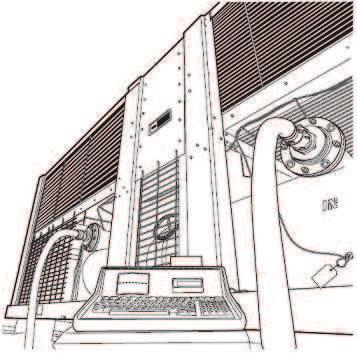
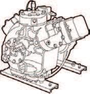


5 Features/Benefits (cont) 0E COMPRESSOR PARTLOAD EFFICIENCY 8% GAIN ELECTRONIC EXPANSION VALVE (EXV) SCROLLING MARQUEE DISPLAY FACTORY SERVICE TEST
6 Model Number Nomenclature GT Aircooled Liquid Chiller Compressor Start N Across Theline Start with ComfortLink TM Controls R PartWind Start with ComfortLink Controls Unit Sizes* Module Designation (40 unit sizes only)* A B Convenience Group Options Marquee display E Energy management board/ Marquee display U Navigator, energy management option, service port option LEGEND EXV Electronic Expansion Valve * Refer to unit sizes and modular combinations below. GT N 1 E C 9 4 Options NOTE: contact your Carrier representative for details on available factoryinstalled options Packaging Standard (top & bottom skid,coil protection and bag) Optional coil protecion & skid 4 Optional full crate Optional code # plus security grilles 7 Optional code # plus security grilles 8 Optional code #4 plus security grilles 9 Flying Bird packaging 0 Optional code #9 plus security grilles Unit design revision VPhHz 5 08/0 9 80/4 Condenser Coil Options Copper Tube, Aluminium Fins C Copper Tube, Copper Fins G Copper Tube, Precoated Aluminium Fins(Gold fin) B Copper Tube, Postcoated Aluminium Fins (Blygold PoluAL) UNIT SIZES AND MODULAR COMBINATIONS UNIT MODEL GTN, GTR * 0Hz units / Hz units NOMINAL TONS SECTION A UNIT GTN, GTR SECTION B UNIT GTN, GTR /170 *
7 GTN,GTR UNIT SIZE SYSTEM MODULES APPROX OPERATING WEIGHT (kg) CuAl CuCu REFRIGERANT TYPE R Charge, Total/Over Clear Glass (kg) Ckt A 1.8/54./. 1.7/.8 5.4/.8 5.4/ / /9.1 Ckt B 7./54 4.5/. 1./.8 5.4/.8 5.4/ / /9.1 COMPRESSORS Reciprocating, SemiHermetic Speed (r/s) 9. 0E* (Qty) Ckt A (Qty) Ckt B (1) 5 (1) 75 (1) 75 (1) 99 (1) 99 (1) 99 (1), (1) 75 (1) 99 (1), (1) 5 () 5 (1) 5, (1) 75 (1) 5, (1) 75 (1) 5, (1) 99 (1) 5, (1) 75 Oil Charge (Compressor/L) /., 5/9.0, 75/9.0, 99/9.0 No. Capacity Control Steps Capacity (%) Ckt A Ckt B Minimum Capacity Step (%) CONDENSER FANS Propeller, Direct Drive Standard Fan Speed (r/s) 19.0 No. Blades...Dia. (mm) No. Fans... (each) Total Airflow 1,045 5,540 4,08,898,898 5,84 5,84 High Static Fan Speed (r/s) 9.0 No. Blades...Dia. (mm) No. Fans... (each) Total Airflow 18,87 8, 8, 8, 8, 7,7 7,7 CONDENSER COILS 9.5 mm OD, Vertical and Horizontal, Plate Fin, Enhanced Copper Tubing Fins/m. No. Rows (Ckt A or B) Face Area, Ckt A and B Total (sq m) Max Working Pressure Refrigerant (kpa) 10 COOLER One... Direct Expansion, Shell and Tube Weight (empty, kg) No. Refrigerant Circuits Net Water Volume, includes nozzles (L) Max Working Pressure Refrigerant Side (kpa) 191 Max Working Pressure Fluid Side (kpa) 08 FLUID CONNECTIONS (in.) Victaulic Type Inlet and Outlet Drain (NPT) /4 0Hz Physical Data LEGEND CuAl Copper Tubing Aluminum Fins Condenser Coil CuCu Copper Tubing Copper Fins Condenser Coil OD Outside Diameter *0E compressors have 4 cylinders; all others have. NOTE: Facing the compressors, Circuit A is on the right and Circuit B is on the left. 5
8 0 Hz (cont) GTN,GTR UNIT SIZE SYSTEM MODULES A B Total APPROX OPERATING WEIGHT (kg) CuAl CuCu REFRIGERANT TYPE R Charge, Total/Over Clear Glass (kg) Ckt A Ckt B 0.5/1.7 7./1.7 5./.9 5.0/.9 9.5/0.5 7./ /1. 78./1. 8.4/ / /.9 5.0/.9 5.4/.8 5.4/.8 / / COMPRESSORS Reciprocating, SemiHermetic Speed (r/s) 9. 0E* (Qty) Ckt A (Qty) Ckt B (1) 75, (1) 99 (1) 75, (1) 99 () 5 () 99 () 75 () 75 (1) 5, (1) 75, (1) 99 (1) 5, (1) 75, (1) 99 () 5, (1) 75 (1) 75, () 99 () 5 () 99 (1), (1) 75 (1) 99 / / Oil Charge (Compressor/L) /., 5/9.0, 75/9.0, 99/9.0 No. Capacity Control Steps Capacity (%) Ckt A 5 Ckt B 44 Minimum Capacity Step (%) CONDENSER FANS Propeller, Direct Drive Standard Fan Speed (r/s) No. Blades...Dia. (mm) No. Fans... (each) Total Airflow High Static Fan Speed (r/s) No. Blades...Dia. (mm) No. Fans... (each) Total Airflow , , , , , , , , , , , , , , , ,5 CONDENSER COILS 9.5 mm OD, Vertical and Horizontal, Plate Fin, Enhanced Copper Tubing Fins/m No. Rows (Ckt A or B) Face Area, Ckt A and B Total (sq m) Max Working Pressure Refrigerant (kpa) COOLER One...Direct One Per Expansion, Shell Expansion, Shell and Tube Module...Direct and Tube Weight (empty, kg) No. Refrigerant Circuits 4 Net Water Volume, includes nozzles (L) Max Working Pressure Refrigerant Side kpa) Max Working Pressure Fluid Side (kpa) FLUID CONNECTIONS (in.) Inlet and Outlet Drain (NPT) LEGEND CuAl Copper Tubing Aluminum Fins Condenser Coil CuCu Copper Tubing Copper Fins Condenser Coil OD Outside Diameter *0E compressors have 4 cylinders; all others have. NOTE: Facing the compressors, Circuit A is on the right and Circuit B is on the left. /4 Victaulic Type 4.8 Physical Data (cont)
9 0 Hz (cont) GTN,GTR UNIT SIZE SYSTEM MODULES A B Total A B Total A B Total APPROX OPERATING WEIGHT (kg) CuAl ,047 CuCu ,057 REFRIGERANT TYPE R Charge, Total/Over Clear Glass (kg) Ckt A Ckt B 5.0/.9 5.0/.9 5.4/.8 5.4/.8 / / 5.0/.9 5.0/ / /9.0 / / 9.5/0.5 7./ / /9.1 / / COMPRESSORS Reciprocating, SemiHermetic Speed (r/s) 9. 0E* (Qty) Ckt A (Qty) Ckt B () 5 () 99 (1) 5, (1) () 5 () 5 () 99 (1) 5, (1) 75 (1) 5, (1) 75 () 75 () 75 (1) 5, (1) 75 (1) 5, (1) 75 Oil Charge (Compressor/L) /., 5/9.0, 75/9.0, 99/9.0 No. Capacity Control Steps Capacity (%) Ckt A 47 Ckt B 5 Minimum Capacity Step (%) CONDENSER FANS Standard Propeller, Direct Drive Fan Speed (r/s) No. Blades...Dia. (mm) No. Fans... (each) Total Airflow High Static Fan Speed (r/s) No. Blades...Dia. (mm) No. Fans... (each) Total Airflow CONDENSER COILS Fins/m No. Rows (Ckt A or B) Face Area, Ckt A and B Total (sq m) Max Working Pressure Refrigerant (kpa) COOLER Weight (empty, kg) No. Refrigerant Circuits Net Water Volume, includes nozzles (L) Max Working Pressure Refrigerant Side (kpa) Max Working Pressure Fluid Side (kpa) FLUID CONNECTIONS (in.) , , , , , , , , , , , , , , mm OD, Vertical and Horizontal, Plate Fin, Enhanced Copper Tubing One Per Module...Direct.1 10 Expansion, Victaulic Type.5 Shell and Tube Inlet and Outlet Drain (NPT) /4 /4 /4 /4 /4 /4 LEGEND CuAl Copper Tubing Aluminum Fins Condenser Coil CuCu Copper Tubing Copper Fins Condenser Coil OD Outside Diameter *0E compressors have 4 cylinders; all others have. NOTE: Facing the compressors, Circuit A is on the right and Circuit B is on the left , , , , Physical Data (cont) 7
10 8 0 Hz (cont) GTN,GTR UNIT SIZE 90 SYSTEM MODULES A B Total A B Total A B Total APPROX OPERATING WEIGHT (kg) CuAl , , , CuCu , , ,4 REFRIGERANT TYPE R Charge, Total/Over Clear Glass (kg) Ckt A Ckt B COMPRESSORS 80.9/1. 78./ / /9.1 / / Reciprocating, SemiHermetic Speed (r/s) 9. 0E* (Qty) Ckt A (Qty) Ckt B (1) 5, (1) 75, (1) 99 (1) 5, (1) 75, (1) 99 (1) 5, (1) 99 (1) 5, (1) 75 () 5, (1) 75 (1) 75, () 99 (1) 5, (1) 99 (1) 5, (1) 75 () 75 () 75 () 75 () 75 Oil Charge (Compressor/L) 5/9.0, 75/9.0, 99/9.0 No. Capacity Control Steps Capacity (%) Ckt A Ckt B 4 4 Minimum Capacity Step (%) CONDENSER FANS Standard Fan Speed (r/s) No. Blades...Dia. (mm) No. Fans... (each) Total Airflow High Static Fan Speed (r/s) No. Blades...Dia. (mm) No. Fans... (each) Total Airflow CONDENSER COILS Fins/m No. Rows (Ckt A or B) Face Area, Ckt A and B Total (sq m) Max Working Pressure Refrigerant (kpa) COOLER Weight (empty, kg) No. Refrigerant Circuits Net Water Volume, includes nozzles (L) Max Working Pressure Refrigerant Side (kpa) Max Working Pressure Fluid Side (kpa) FLUID CONNECTIONS (in.) Inlet and Outlet Drain (NPT) , , / , , / , ,80 8.4/ / / /9.1 Propeller, Direct Drive , , , ,7 / / , , mm OD, Vertical and Horizontal, Plate Fin, Enhanced Copper Tubing One Per Module...Direct Expansion, Shell and Tube Victaulic Type / / /0.5 7./ , , /4 9.5/0.5 7./ , , /4 / / , , Physical Data (cont) LEGEND CuAl Copper Tubing Aluminum Fins Condenser Coil CuCu Copper Tubing Copper Fins Condenser Coil OD Outside Diameter *0E compressors have 4 cylinders; all others have. NOTE: Facing the compressors, Circuit A is on the right and Circuit B is on the left.
11 0 Hz (cont) GTN,GTR UNIT SIZE SYSTEM MODULES A B Total A B Total A B Total APPROX OPERATING WEIGHT (kg) CuAl ,5 081 CuCu , REFRIGERANT TYPE R Charge, Total/Over Clear Glass (kg) Ckt A 80.9/ /1. / 8.4/18. Ckt B 78./1. 78./1. / 84.1/ /1. 78./1. COMPRESSORS Reciprocating, SemiHermetic Speed (r/s) 9. 0E* (Qty) Ckt A (Qty) Ckt B (1) 5, (1) 75, (1) 99 (1) 5, (1) 75, (1) 99 (1) 5, (1) 75, (1) 99 (1) 5, (1) 75, (1) 99 () 5, (1) 75 (1) 75, () 99 (1) 5, (1) 75, (1) 99 (1) 5, (1) 75, (1) 99 11,84 1,4 / / / /18. () 5, (1) 75 (1) 75, () / /18. () 5, (1) 75 (1) 75, () 99 Oil Charge (Compressor/L) 5/9.0, 75/9.0, 99/9.0 No. Capacity Control Steps Capacity (%) Ckt A Ckt B Minimum Capacity Step (%) CONDENSER FANS Standard Propeller, Direct Drive Fan Speed (r/s) No. Blades...Dia. (mm) No. Fans... (each) Total Airflow High Static Fan Speed (r/s) No. Blades...Dia. (mm) No. Fans... (each) Total Airflow CONDENSER COILS Fins/m No. Rows (Ckt A or B) Face Area, Ckt A and B Total (sq m) Max Working Pressure Refrigerant (kpa) COOLER Weight (empty, kg) No. Refrigerant Circuits Net Water Volume, includes nozzles (L) Max Working Pressure Refrigerant Side (kpa) Max Working Pressure Fluid Side (kpa) FLUID CONNECTIONS (in.) Inlet and Outlet Drain (NPT) , , /4 LEGEND CuAl Copper Tubing Aluminum Fins Condenser Coil CuCu Copper Tubing Copper Fins Condenser Coil OD Outside Diameter *0E compressors have 4 cylinders; all others have. NOTE: Facing the compressors, Circuit A is on the right and Circuit B is on the left , , / , , , , , , , ,0 9.5 mm OD, Vertical and Horizontal, Plate Fin, Enhanced Copper Tubing One Per Module...Direct Victaulic Type / Expansion, / Shell and Tube , , / , , /4 1,1 1,544 / / , , Physical Data (cont) 9
12 10 Hz GTN,GTR UNIT SIZE SYSTEM MODULES APPROX OPERATING WEIGHT (kg) CuAl CuCu REFRIGERANT TYPE R Charge, Total/Over Clear Glass (kg) Ckt A 1.8/5.4./../.8 5.4/.8 5.4/ / /9.1 Ckt B 7./ /. 1./.8 5.4/.8 5.4/ / /9.1 COMPRESSORS Reciprocating, SemiHermetic Speed (r/s) 4. 0E* (Qty) Ckt A (Qty) Ckt B (1) 75 (1) 99 (1) 99 (1) 99 (1) 5, (1) 5 (1) 99 (1) 5, (1) 99 (1) 99 (1) 5, (1) 99 (1) 5, (1) 75 Oil Charge (Compressor/L) /., 5/9.0, 75/9.0, 99/9.0 (1) 5, (1) 99 (1) 5, (1) 99 No. Capacity Control Steps Capacity (%) Ckt A Ckt B Minimum Capacity Step (%) CONDENSER FANS Propeller, Direct Drive Standard Fan Speed (r/s).8 No. Blades...Dia. (mm)...7 No. Fans... (each) Total Airflow 1,045 5,540 4,08,898,898 5,84 5,84 High Static Fan Speed (r/s) 4.1 No. Blades...Dia. (mm) No. Fans... (each) Total Airflow 18,87 8, 8, 8, 8, 7,7 7,7 CONDENSER COILS 9.5 mm OD, Vertical and Horizontal, Plate Fin, Enhanced Copper Tubing Fins/m. No. Rows (Ckt A or B) Face Area, Ckt A and B Total (sq m) Max Working Pressure Refrigerant (kpa) 10 COOLER One... Direct Expansion, Shell and Tube Weight (empty, kg) No. Refrigerant Circuits Net Water Volume, includes nozzles (L) Max Working Pressure Refrigerant Side (kpa) 191 Max Working Pressure Fluid Side (kpa) 08 FLUID CONNECTIONS (in.) Victaulic Type Inlet and Outlet Drain (NPT) /4 LEGEND CuAl Copper Tubing Aluminum Fins Condenser Coil CuCu Copper Tubing Copper Fins Condenser Coil OD Outside Diameter *0E compressors have 4 cylinders; all others have. NOTE: Facing the compressors, Circuit A is on the right and Circuit B is on the left. () 99 () 99 Physical Data (cont)
13 Hz (cont) GTN,GTR UNIT SIZE SYSTEM MODULES A B Total APPROX OPERATING WEIGHT (kg) CuAl CuCu REFRIGERANT TYPE R Charge, Total/Over Clear Glass (kg) Ckt A Ckt B COMPRESSORS 0.5/1.7./ /.9 5.0/.9 9.5/0.5 7./ /1. 78./1. 8.4/ /18. Reciprocating, SemiHermetic Speed (r/s) 4. 0E* (Qty) Ckt A (Qty) Ckt B (1) 5, () 75 () 99 () 99 () 99 () 75, (1) 99 (1) 75, () 99 () 99 () 99 () 5, () 99 () /.9 /.9 () 99 () /.8 5.4/.8 (1) 5, (1) 99 (1) 99 Oil Charge (Compressor/L) 5/9.0, 75/9.0, 99/9.0 No. Capacity Control Steps Capacity (%) Ckt A Ckt B Minimum Capacity Step (%) CONDENSER FANS Standard Propeller, Direct Drive Fan Speed (r/s) No. Blades...Dia. (mm) No. Fans... (each) Total Airflow High Static Fan Speed (r/s) No. Blades...Dia. (mm) No. Fans... (each) Total Airflow CONDENSER COILS Fins/m No. Rows (Ckt A or B) Face Area, Ckt A and B Total (sq m) Max Working Pressure Refrigerant (kpa) , , , , , , , , , , , , mm OD, Vertical and Horizontal, Plate Fin, Enhanced Copper Tubing , , COOLER One...Direct Expansion, Shell and Tube One Per Module...Direct Expansion, Shell and Tube Weight (empty, kg) No. Refrigerant Circuits Net Water Volume, includes nozzles (L) Max Working Pressure Refrigerant Side (kpa) Max Working Pressure Fluid Side (kpa) FLUID CONNECTIONS (in.) Victaulic Type Inlet and Outlet 4 Drain (NPT) /4 LEGEND CuAl Copper Tubing Aluminum Fins Condenser Coil CuCu Copper Tubing Copper Fins Condenser Coil OD Outside Diameter *0E compressors have 4 cylinders; all others have. NOTE: Facing the compressors, Circuit A is on the right and Circuit B is on the left / / / / , ,5.8 Physical Data (cont) 11
14 1 Hz (cont) GTN,GTR UNIT SIZE SYSTEM MODULES A B Total A B Total A B Total APPROX OPERATING WEIGHT (kg) CuAl ,11 CuCu ,19 REFRIGERANT TYPE R Charge, Total/Over Clear Glass (kg) Ckt A Ckt B 5.0/.9 /.9 5.4/.8 5.4/.8 / / 5.0/.9 / / /9.1 / / 9.5/0.5 7./ / /9.1 / / COMPRESSORS Reciprocating, SemiHermetic Speed (r/s) 4. 0E* (Qty) Ckt A (Qty) Ckt B () 99 () 99 (1) 5, (1) 99 (1) 5, (1) 75 () 99 () 99 (1) 5, (1) 99 (1) 5, (1) 99 () 75, (1) 99 (1) 75, () 99 (1) 5, (1) 99 (1) 5, (1) 99 Oil Charge (Compressor/L) 5/9.0, 75/9.0, 99/9.0 No. Capacity Control Steps Capacity (%) Ckt A Ckt B Minimum Capacity Step (%) CONDENSER FANS Standard Propeller, Direct Drive Fan Speed (r/s) No. Blades...Dia. (mm) No. Fans... (each) Total Airflow High Static Fan Speed (r/s) No. Blades...Dia. (mm) No. Fans... (each) Total Airflow CONDENSER COILS Fins/m No. Rows (Ckt A or B) Face Area, Ckt A and B Total (sq m) Max Working Pressure Refrigerant (kpa) COOLER Weight (empty, kg) No. Refrigerant Circuits Net Water Volume, includes nozzles (L) Max Working Pressure Refrigerant Side (kpa) Max Working Pressure Fluid Side (kpa) FLUID CONNECTIONS (in.) Inlet and Outlet Drain (NPT) , , / , , /4 LEGEND CuAl Copper Tubing Aluminum Fins Condenser Coil CuCu Copper Tubing Copper Fins Condenser Coil OD Outside Diameter *0E compressors have 4 cylinders; all others have. NOTE: Facing the compressors, Circuit A is on the right and Circuit B is on the left , , , , , , , , , , mm OD, Vertical and Horizontal, Plate Fin, Enhanced Copper Tubing One Per /4 Module...Direct.1 10 Expansion, Victaulic Type 5 /4.5 Shell and Tube / , , / , , Physical Data (cont)
15 Hz (cont) GTN,GTR UNIT SIZE 90 SYSTEM MODULES A B Total A B Total A B Total APPROX OPERATING WEIGHT (kg) CuAl , ,40 CuCu , , ,558 REFRIGERANT TYPE R Charge, Total/Over Clear Glass (kg) Ckt A Ckt B 80.9/1. 78./ / /9.1 / / 8.4/ / / /9.1 / / 9.5/0.5 7./ /0.5 7./0.5 / / COMPRESSORS Reciprocating, SemiHermetic Speed (r/s) 4. 0E* (Qty) Ckt A (Qty) Ckt B () 99 () 99 () 99 () 99 () 5, () 99 () 99 () 99 () 99 () 75, (1) 99 (1) 75, () 99 () 75, (1) 99 (1) 75, () 99 Oil Charge (Compressor/L) 5/9.0, 75/9.0, 99/9.0 No. Capacity Control Steps Capacity (%) Ckt A Ckt B Minimum Capacity Step (%) CONDENSER FANS Standard Propeller, Direct Drive Fan Speed (r/s) No. Blades...Dia. (mm) No. Fans... (each) Total Airflow High Static Fan Speed (r/s) No. Blades...Dia. (mm) No. Fans... (each) Total Airflow CONDENSER COILS Fins/m No. Rows (Ckt A or B) Face Area, Ckt A and B Total (sq m) Max Working Pressure Refrigerant (kpa) , , , , , , , , , , , , , , mm OD, Vertical and Horizontal, Plate Fin, Enhanced Copper Tubing COOLER One Per Module...Direct Expansion, Shell and Tube Weight (empty, kg) No. Refrigerant Circuits Net Water Volume, includes nozzles (L) Max Working Pressure Refrigerant Side (kpa) Max Working Pressure Fluid Side (kpa) FLUID CONNECTIONS (in.) Victaulic Type , ,190 Inlet and Outlet 5 5 Drain (NPT) /4 /4 /4 /4 /4 /4 LEGEND CuAl Copper Tubing Aluminum Fins Condenser Coil CuCu Copper Tubing Copper Fins Condenser Coil OD Outside Diameter *0E compressors have 4 cylinders; all others have. NOTE: Facing the compressors, Circuit A is on the right and Circuit B is on the left , , Physical Data (cont) 1
16 14 LEGEND CuAl Copper Tubing Aluminum Fins Condenser Coil CuCu Copper Tubing Copper Fins Condenser Coil OD Outside Diameter *0E compressors have 4 cylinders; all others have. NOTE: Facing the compressors, Circuit A is on the right and Circuit B is on the left. Hz (cont) GTN,GTR UNIT SIZE SYSTEM MODULES A B Total A B Total A B Total APPROX OPERATING WEIGHT (kg) CuAl , ,0 1,1 CuCu , , ,94 REFRIGERANT TYPE R Charge, Total/Over Clear Glass (kg) Ckt A Ckt B 80.9/1. 78./ /1. 7./1. / / 8.4/ / /1. 78./1. / / 8.4/ / / /18. / / COMPRESSORS Reciprocating, SemiHermetic Speed (r/s) 4. 0E* (Qty) Ckt A (Qty) Ckt B () 99 () 99 () 75, (1) 99 (1) 75, () 99 () 5, () 99 () 99 () 99 () 99 () 5, () 99 () 99 () 5, () 99 () 99 Oil Charge (Compressor/L) 5/9.0, 75/9.0, 99/9.0 No. Capacity Control Steps Capacity (%) Ckt A Ckt B Minimum Capacity Step (%) CONDENSER FANS Standard Propeller, Direct Drive Fan Speed (r/s) No. Blades...Dia. (mm) No. Fans... (each) Total Airflow High Static Fan Speed (r/s) No. Blades...Dia. (mm) No. Fans... (each) Total Airflow CONDENSER COILS Fins/m No. Rows (Ckt A or B) Face Area, Ckt A and B Total (sq m) Max Working Pressure Refrigerant (kpa) COOLER Weight (empty, kg) No. Refrigerant Circuits Net Water Volume, includes nozzles (L) Max Working Pressure Refrigerant Side (kpa) Max Working Pressure Fluid Side (kpa) FLUID CONNECTIONS (in.) , , , , , , , , , , , , , , 9.5 mm OD, Vertical and Horizontal, Plate Fin, Enhanced Copper Tubing One Per Module...Direct Expansion, Victaulic Type 49.9 Shell and Tube , , Inlet and Outlet Drain (NPT) /4 /4 /4 /4 /4 / , , Physical Data (cont)
17 Factoryinstalled options heater helps protect the cooler to 0 F ( 9 C). NOTE: For ambient temperatures below F (0 C), inhibited glycol antifreeze solutions are recommended to prevent freezeup in the event of power failure. Sound reduction option consists of specially designed system of fans and acoustic enclosures for reducing sound levels without compromising chiller performance. For Hz units, this option uses lownoise AeroAcoustic (Flying Bird) fans and taller discharge stacks. (Additional packaging is required. See Price Pages for further details.) Partwind (PW) start generally is not required where multiple 0E compressors are installed. The starting current is usually lower than a larger compressor using PW start. However, a partwind start option is available (denoted by a R in the fifth position of the unit model number) for all sizes. For 110, A40A, and B40B sizes, disconnect on the center panel on the cooler side of the chiller. Highstatic fans allow the GTN,GTR units to be used in applications with an external static pressure of up to 0.4 in. wg ( kpa) (external to the chiller) at nominal condenser airflow. Condenser coil options Several options are available to match coil construction to the site conditions for the best durability. See page 7 for additional details or contact your Carrier representative for further information.

18


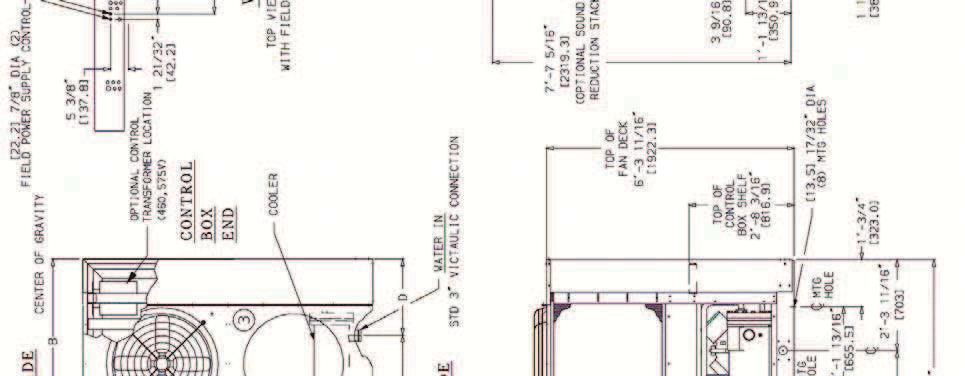
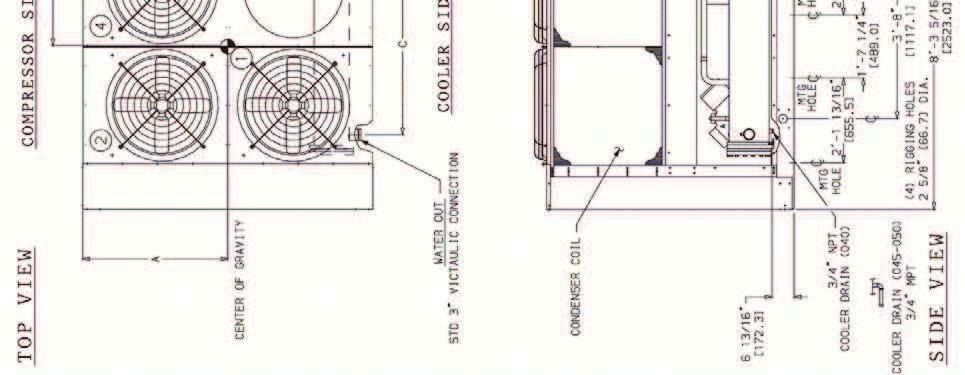
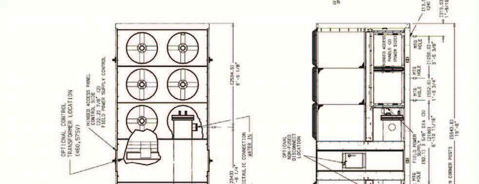
19 E DENOTES COPPER FIN/COPPER TUBING CONDENSER COIL VOLTAGE 08/ /4 FIELD POWER SUPPLY CONNECTIONS UNIT GTN, GTR Hz DIAMETER in. mm /.5 5 / /.5 5 / / /8 9.0 QTY Base unit dimensions GTN,GTR00,070 17


20 Base unit dimensions GTN,GTR /.0 7 / / 18


21 Base unit dimensions GTN,GTR /.0 7 / / 19


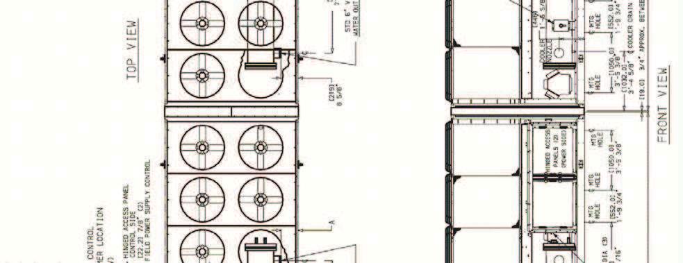
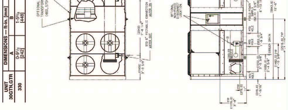
22 Base unit dimensions GTN,GTR, /.0 7 / / 0


23 Base unit dimensions GTN,GTR / / /4 1


24 Base unit dimensions GTN,GTR / / /4

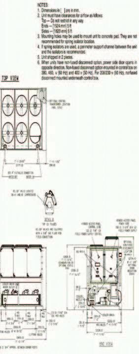
25 Base unit dimensions GTN,GTR, / / /

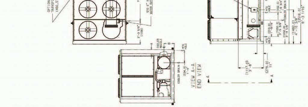

26 Base unit dimensions GTN,GTR55, /.0 7 / / 4
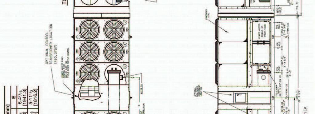
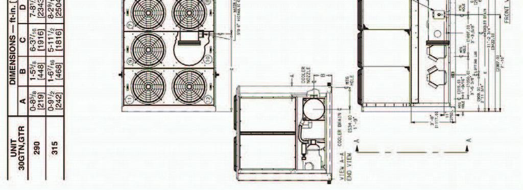

27 Base unit dimensions GTN,GTR90, /.0 7 / / 5
28 Base unit dimensions GTN,GTR.0 7 / /


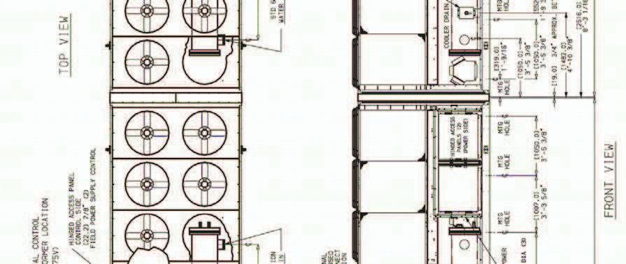
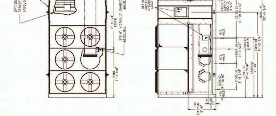
29 Base unit dimensions GTN,GTR0 (Hz).0 7 / / 7
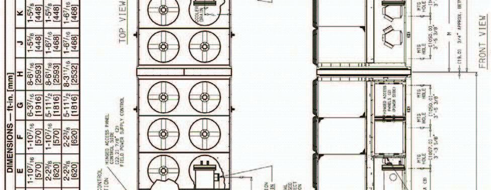
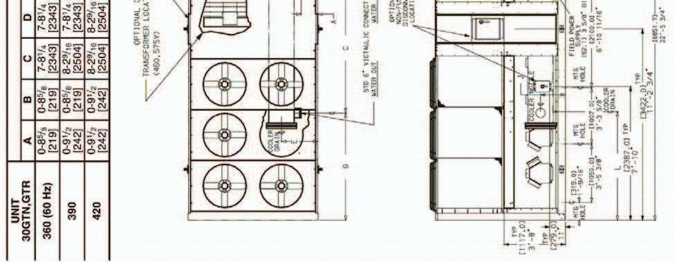
30 Base unit dimensions GTN,GTR0 (0Hz), 90, /.0 7 / 8
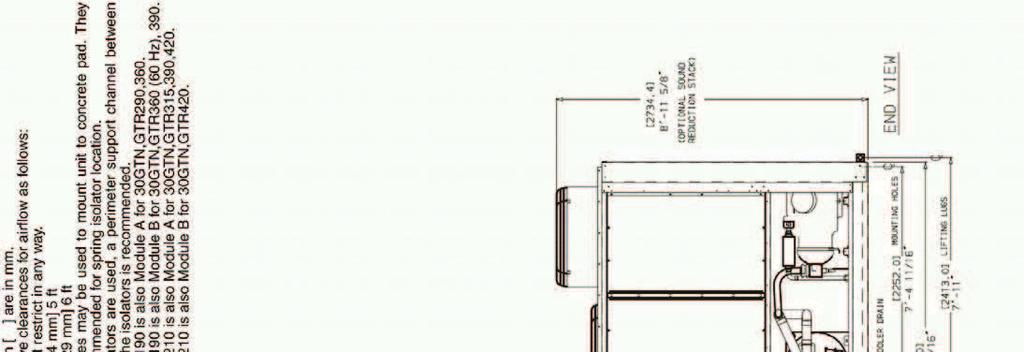
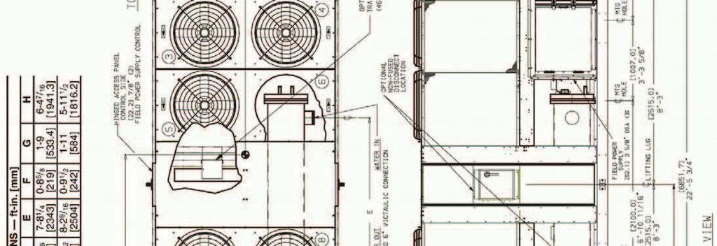
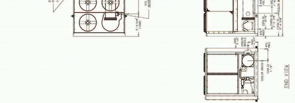
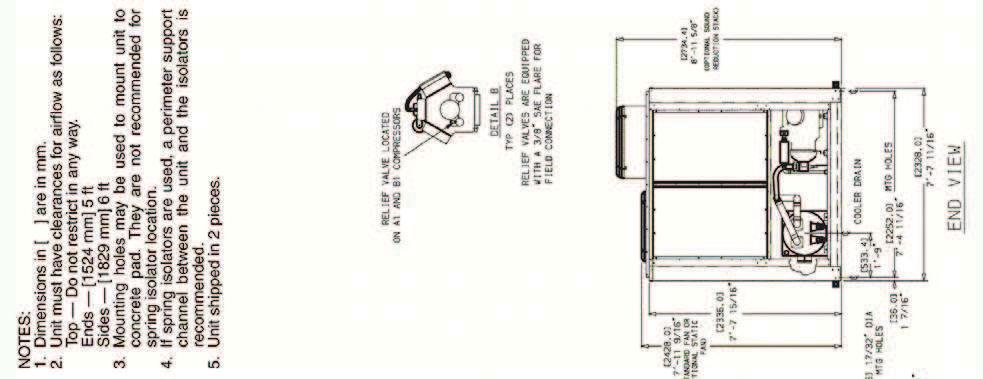
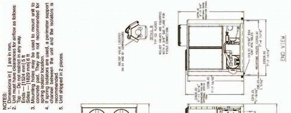
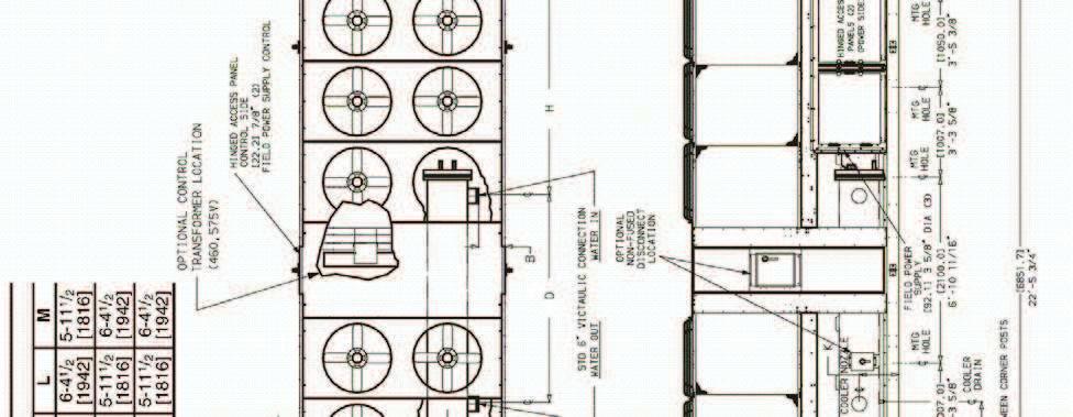
31 Base unit dimensions Mounting weights (approximate) SIZES * D C CONTROL BOX A B UNIT SIZE GTN,GTR CONDENSER COIL CAL CC CAL CC CAL CC CAL CC CAL CC CAL CC CAL CC A B lb C D A B kg C D LEGEND CAL Copper Tubing, Aluminum Fins CC Copper Tubing, Copper Fins * Points A, B, C, and D are located in the corners of the unit. See pages 10 for dimensions Contact your local Carrier representative for more information on postcoated and pre coated aluminum fins. NOTE: If spring isolators are used, a perimeter support channel between the unit and the isolators is recommended. 9
32 Base unit dimensions Mounting weights (approximate) SIZES 1 10 D 11.9 (89) 4. (107) C B 77.9 (1979) SIZES (888) SIZES A COOLER SIDE 91.7 (8) B COMPRESSORS A COMPRESSORS E F G H UNIT SIZE GTN,GTR COND COIL* A B C D lb E F G H A B C D kg E F G H 1 CAL CC CAL CC CAL CC CAL CC CAL CC LEGEND CAL Copper Tubing, Aluminum Fins CC Copper Tubing, Copper Fins * Contact your local Carrier representative for more information on postcoated and precoated aluminum fins. NOTES: 1. Dimensions in ( ) are in millimeters.. If spring isolators are used, a perimeter support channel between the unit and the isolators is recommended.
33 Base unit dimensions Mounting weights (approximate) SIZES (1979) A70A, A/B, 0B (Hz) 11.7 (888) 0A, 0B (0Hz), 90A/B, 40A/B 11.9 (89) 4. (107) CONTROL BOX (BB) POWER BOX (A40A, B40B) B COMPRESSORS UNIT MODULE A OR B CONTROL BOX (A40A, B40B) COOLDER SIDE A COMPRESSORS 91.7 (8) 0Hz UNITS UNIT SIZE GTN, GTR CONDENSER COIL A B C D KG E F G H A,45A,55A B 45B 55B,70B 70A,A/B 90A,0A/B,90B 90B,B A,90A,40A/B CAL CC CAL CC CAL CC CAL CC CAL CC CAL CC CAL CC CAL CC LEGEND CAL Copper Tubing Aluminum Fins CC Copper Tubing Copper Fins NOTES: 1. Dimensions in ( ) are in millimeters.. If spring isolators are used, a perimeter support channel between the unit and the isolators is recommended.. For AD and HE dimensions on BB modules, see pages 180. RIGGING CENTER OF GRAVITY 0Hz UNITS UNIT SIZE GTN,GTR A,45A, 55A in. mm in. B mm in. 45B mm 55B,70B in. mm 70A,A/B in. mm 90A,0A/B, 90B in. mm 90B,B in. mm A,90A, 40A/B in. mm X Dimension 11 1 / /8 14 / / / / /8 444 Y Dimension ½ / / /1 11 ½ 18 ½ 18 5 /1 1 5 /
34 Base unit dimensions Mounting weights (approximate) SIZES (1979) A70A, A/B, 0B (Hz) 11.7 (888) 0A, 0B (0Hz), 90A/B, 40A/B 11.9 (89) 4. (107) CONTROL BOX (BB) POWER BOX (A40A, B40B) B COMPRESSORS UNIT MODULE A OR B CONTROL BOX (A40A, B40B) COOLDER SIDE A COMPRESSORS 91.7 (8) Hz UNITS UNIT SIZE GTN, GTR CONDENSER COIL A B C D KG E F G H A,45A,55A B 45B 55B,70B 70A,A/B 0B 90A,0A,90B 90B,B A,90A,40A/B CAL CC CAL CC CAL CC CAL CC CAL CC CAL CC CAL CC CAL CC LEGEND CAL Copper Tubing Aluminum Fins CC Copper Tubing Copper Fins NOTES: 1. Dimensions in ( ) are in millimeters.. If spring isolators are used, a perimeter support channel between the unit and the isolators is recommended.. For AD and HE dimensions on BB modules, see pages 180. RIGGING CENTER OF GRAVITY Hz UNITS UNIT SIZE GTN,GTR A,45A, 55A in. mm in. B mm in. 45B mm 55B,70B in. mm 70A,A/B in. mm 90A,0A/B, 90B in. mm 90B,B in. mm A,90A, 40A/B in. mm X Dimension 11 1 / /8 14 / / / / /8 444 Y Dimension ½ / / /1 11 ½ 18 ½ 18 5 /1 1 5 /8 185
35 Application Data Leveling Unit Unit must be level within 1/8in. per ft when installed to ensure proper oil return to the compressors. While most outdoor locations are suitable for GTN, GTR units, the roof is a common site that presents a problem if roof has been pitched to aid in water removal. To assure proper oil return, be sure that unit is level, particularly in its major lengthwise dimension, as compressor oil return piping runs in that direction. It should be determined prior to installation if any special treatment is required to assure a level installation. fluid temperature 1. Maximum leaving chilled fluid temperature (LCWT) for unit is 70 F (1 C). Unit can start and pull down with up to 95 F (5 C) enteringfluid temperature due to MOP (maximum operating pressure) feature of the TXV. For sustained operation, it is recommended that enteringfluid temperature not exceed 85 F (9.4 C).. Minimum LCWT for standard unit is 40 F (. C). It is permissible to use a standard microprocessorcontrolled ComfortLink chiller with leavingfluid temperatures in the range of 4 to 9.9 F (1 to.8 C) only if a protective brine solution (0% antifreeze solution, or greater) is used. (See Controls and Troubleshooting literature for further information.) Leavingfluid temperature reset The Energy Management Module (EMM) is required for 4 to 0 ma reset of LCWT in constant fluid systems. Reset by return fluid, outdoorair temperature, or space temperature does not require this option. Reset reduces compressor power usage at part load when design LCWT is not necessary. Humidity control should be considered since higher coil temperatures resulting from reset will reduce latent heat capacity. Three reset options are offered, based on the following: Returnfluid temperature Increases LCWT temperature set point as return (or entering) fluid temperature decreases (indicating load decrease). Option may be used in any application where return fluid provides accurate load indication. Limitation of return fluid reset is that LCWT may only be reset to value of design return fluid temperature. Outdoorair temperature Increases LCWT as outdoor ambient temperature decreases (indicating load decrease). This reset should be applied only where outdoor ambient temperature is an accurate indication of load. An accessory thermistor is required. Space temperature Increases LCWT as space temperature decreases (indicating load decrease). This reset should be applied only where space temperature is an accurate indication of load. An accessory thermistoris required. For details on applying a reset option, refer to unit Controls and Troubleshooting literature. Obtain ordering part numbers for reset option from current price pages or contact your local Carrier representative. flow range Ratings and performance data in this publication are for a cooling temperature rise of 10 F ( C), and are suitable for a range from 5 to 0 F (.8 to 11.1 C) temperature rise without adjustment. The ComfortLink chillers may be operated using a different temperature range, provided flow limits are not exceeded. For minimum flow rates, see Minimum Fluid s and Minimum Loop Volume table. High flow rate is limited by pressure drop that can be tolerated. If another temperature range is used, apply LCWT correction as given in Selection Procedure example on page 4. UNIT SIZE UNIT SIZE MINIMUM COOLER FLUID FLOW RATES AND MINIMUM LOOP VOLUME UNIT SIZES 010 MINIMUM COOLER FLOW RATE Gpm L/s MINIMUM COOLER FLOW RATES AND MINIMUM LOOP VOLUME UNIT SIZES 40 MINIMUM COOLER FLOW RATE Module A Gpm L/s Module B Gpm L/s LEGEND ARI Air Conditioning and Refrigeration Institute N Liters per V Gallons per ton MINIMUM LOOP VOLUME Gal L MINIMUM LOOP VOLUME Gallons NOTES: 1. Minimum flow based on 1.0 fps (0. m/s) velocity in cooler without special cooler baffling... Minimum Loop Volumes: Gallons = V x ARI (tons) Liters = N x ARI APPLICATION Normal Air Conditioning Process Type Cooling Low Ambient Unit Operation V to 10 to 10 Liters N.5.5 to to 10.8
36 Application Data (cont) Minimum cooler flow (maximum cooler tempera ture rise) The minimum cooler flow for standard units is shown in Minimum Fluid s and Minimum Loop Volume tables. When gpm required is lower (or rise higher), follow recommendations below: a) Multiple smaller chillers may be applied in series, each providing a portion of the design temperature rise. b) fluid may be recirculated to raise flow rate. However, mixed temperature entering cooler must be maintained a minimum of at least 5 F (.8 C) above the LCWT. c) Special cooler baffling is required to allow minimum flow rate to be reduced. Fluid loop volume The volume in circulation must equal or exceed gal. per nominal ton (.5 L per ) of cooling for temperature stability and accuracy in normal airconditioning applications. (For example, a GTN10 would require 0 gal. [ L].) In process cooling applications, or for operation at ambient temperature below F (0 C) with low loading conditions, there should be from to 10 gal. per ton (.5 to 10.8 L per ). To achieve this volume, it is often necessary to install a tank in the loop. Tank should be baffled to ensure there is no stratification and that water (or brine) entering tank is adequately mixed with liquid in the tank. NOTE: Tank installation is shown below. NOTE: Recirculation flow is shown below. Maximum cooler flow The maximum cooler flow (> 5 gpm/ton or < 5 F rise [> 0.09 L/s or <.7 C rise]) results in practical maximum pressure drop through cooler. 1. Return fluid may bypass the cooler to keep pressure drop through cooler within acceptable limits. This permits a higher T with lower fluid flow through cooler and mixing after the cooler.. Special cooler baffling to permit a cooler flow rate increase of 10% is available by special order. NOTE: Bypass flow is shown below. Variable cooler flow rates Variable rates may be applied to standard chiller. Unit will, however, attempt to maintain a constant leaving chilled fluid temperature. In such cases, minimum flow must be in excess of minimum flow given in Minimum Fluid s and Minimum Loop Volume table, and flow rate must change in steps of less than 10% per minute. Apply gal. per ton (.5 L per ) water loop volume minimum if flow rate changes more rapidly. fouling factor The fouling factor used to calculate tabulated ratings was ft hr F/ Btu ( m C/W). As fouling factor is increased, unit capacity decreases and compressor power increases. Standard ratings should be corrected using following multipliers: FOULING FACTOR English (ft² hr F/Btu) SI (m² C/W) CAPACITY MULTIPLIER COMPRESSOR POWER MULTIPLIER protection Protection against low ambient freezeup is required for unit operation in areas that experience temperatures below F (0 C). Protection should be in the form of inhibited ethylene glycol or other suitable brine. Even though unit cooler is equipped with insulation and an electric heater that helps prevent freezeup, it does not protect fluid piping external to unit or if there is a power failure. Use only antifreeze solutions approved for heat exchanger duty. Use of automotivetype antifreezes is not recommended because of the fouling that can occur once their relatively shortlived inhibitor breaks down. Draining cooler and outdoor piping is recommended if system is not to be used during freezing weather conditions. 4
37 Application Data (cont) Condenser Altitude correction factors Correction factors must be applied to standard ratings at altitudes above 000 ft (10 m) using the following multipliers: ALTITUDE ft m CAPACITY MULTIPLIER COMPRESSOR POWER MULTIPLIER Condenser airflow Airflow restrictions on units with standard fans will affect the unit capacity, condenser head pressure, and compressor power input. Correction factors to be applied for external static restrictions up to 0. in. wg ( Pa) are as follows: EXTERNAL STATIC In. wg Pa CAPACITY MULTIPLIER COMPRESSOR POWER MULTIPLIER High static fan options These should be used to prevent a reduction in airflow to the conditioned space whenever an application requires external ductwork which will raise the job static requirements. High ambient temperature High outdoor ambient chiller startup and operation (fully loaded) is possible for standard GTN,GTR chillers at ambient temperatures up to 15 F (5 C) at nominal voltage. In some cases, where return water temperature is expected to exceed 0 F (.5 C), an accessory kit may be required. Antifreeze solution Inhibited ethylene glycol or other suitable corrosionresistant antifreeze solution must be field supplied and installed in all units for unit operation below F (0 C). Solution must be added to fluid loop to protect loop down to F (8 C) below minimum operating ambient temperature. Concentration should be based on expected minimum temperature and either Burst or Freeze protection levels. Provide sufficient volume in the chilled fluid loop At least gal per ton (.5 L per ) of refrigeration is the recommended minimum for a moderate system load. Freeze versus burst protection If chiller operation is not required during winter/off season, lower glycol concentrations based on burst protection criteria may be considered. Often use of burst protection results in lower fluid costs and has less impact on chiller cooler capacity and flow rate. Consult glycol fluid manufacturers for burst protection recommendations and fluid specifications. example. Correction factors can be derived from curves in the Inhibited Ethylene Glycol Performance chart at right. Additional performance information on this and other fluids is available in Carrier s Electronic Catalog (ECAT) software program. Slush and Burst concentration may also be considered for winter shutdown protection and unit operation is not required. Example: English Where a 5 F outdoor temperature is anticipated, determine concentration of inhibited ethylene glycol to protect system to 10 F ambient temperature at zero flow. Enter the solution crystallization point curve (at right) at 10 F; read that 40% concentration of inhibited ethylene glycol is required to prevent crystals from forming in solution. Consider the GTN110 unit from the Selection Procedure example on page 4 (refer to correction curves at 40% solution). Correct unit capacity On the capacity correction curve in chart on page, read Corrected capacity = 0.95 x determined capacity = 0.95 x 11. = tons Correct cooler water flow On the cooler flow correction curve on page, read 1.. Chilled water flow (at corrected capacity) = = 4 x corrected cap. In tons temperature rise F 4 x = 18.4 U.S. gpm U.S. gpm Chilled water flow (40% solution) = 1. x 18.4 = 10.9 U.S. gpm Correct cooler pressure drop On cooler pressure drop correction curve on page, read 1.. On cooler pressure drop curve on page 49, for 10.9 gpm, read pressure drop = 8.1 ft water gage. The pressure drop for 40% solution = 1. x 8.1 = 10.8 ft water. Correct compressor power input On power correction curve below, read 0.97 correction factor at 40% ethylene glycol concentration. Power input from Selection Procedure example = 1.1. Corrected power input = 0.97 x 1.1 = 1. = Capacity correction (antifreeze) Inhibited ethylene glycol (or other suitable brine) should be used in installations where subfreezing temperatures are expected. Unit performance data must be corrected for the addition of inhibited ethylene glycol as shown in following 5

38 Application Data (cont) Chilled water flow (40% solution) = 1. x 11.1 = 1.8 L/s Correct cooler pressure drop On cooler pressure drop correction curve on this page, read 1.. On cooler pressure drop curve on page 8, for 1.8 L/s, read pressure drop of 4 kpa. The pressure drop for 40% solution = 1. x 4 = 1.9 kpa. Correct compressor power input On the power correction curve on this page, read 0.97 correction factor at 40% ethylene glycol concentration. Power input from Selection Procedure example = 1.. Corrected power input = 0.97 x 1. = Oversizing chillers Oversizing chillers by more than % at design conditions must be avoided as the system operating efficiency is adversely affected (resulting in greater or excessive electrical demand). When future expansion of equipment is anticipated, install a single chiller to meet present load requirements and add a second chiller to meet the additional load demand. It is also recommended that smaller chillers be installed where operation at minimum load is critical. The operation of a smaller chiller loaded to a greater percentage over minimum is preferred to operating a single chiller at or near its minimum recommended value. Hot gas bypass should not be used as a means to allow oversizing chillers. Hot gas bypass should be given consideration where substantial operating time is anticipated below the minimum unloading step. Example: Determine concentration of inhibited ethylene glycol to protect the system to C ambient temperature at zero flow. Enter the solution crystallization point curve above, at C, read 40% concentration inhibited ethylene glycol is required to prevent crystals from forming in solution. Consider GTN110 unit selected from the Selection Procedure example (refer to correction curves at 40% solution). Correct unit capacity On glycol performance capacity correction curve above, read Corrected capacity = 0.95 x determined capacity = 0.95 x 79.7 = 0.7 Correct chilled water flow On cooler flow correction curve above, read 1.. Chilled water flow (at corrected capacity) = 0.9 x corr. Cap in temperature rise C = L/S Multiple chillers Where chiller capacities greater than 10 tons (740 ) are required, or where standby capability is desired, chillers may be installed in parallel. Units should be of equal size to ensure balanced fluid flows. Where a large temperature drop (> 5 F [1.9 C]) is desired, chillers may be installed series. Fluid temperature sensors need not be moved for multiple chiller operation. A 10 ft ( m) separation is required between units for airflow, and a ft (1.8 m) distance is required from units to obstructions. See Multiple Unit Separation figure below. Unit software is capable of controlling two units as a single plant. Refer to Controls, StartUp, Operation, Service, and Troubleshooting guide for further details. = 0.9 x = 11.1 L/s
39 Application Data (cont) Electrical/utility interests Energy management Use of energy management practices can significantly reduce operating costs, especially during offpeak modes of operation. Demand limiting and temperature reset are techniques for accomplishing efficient energy management. See Demand Limiting (also called load shedding) section below and LeavingFluid Temperature Reset section on page for further details. Demand limiting (also called load shedding) When a utility s demand for electricity exceeds a certain level, loads are shed to keep electricity demand below a prescribed maximum level. Typically, this happens on hot days when air conditioning is most needed. The Energy Management Module (EMM) can be added to accomplish this reduction. Demand may be limited on unit by resetting fluid temperature, or by unloading the chiller to a given predetermined percentage of the load. Demand limit may also be driven by an external 4 to 0 ma signal. These features require a signal from an intelligent central control. Do not cycle demand limiter for less than 10 minutes on and 5 minutes off. Duty cycling cycles electrical loads at regular intervals regardless of need. This reduces the electrical operating costs of building by fooling demand indicating devices. Duty cycling of compressors or fans is not recommended since motor winding and bearing life suffer from constant cycling. Remote onoff control Remote onoff control may be applied by hardwired connection (see Controls and Troubleshooting literature) or by connection to a Carrier Comfort Network (CCN). Partwind start This is not generally required on GTN,GTR chillers due to use of multiple compressors allowing smaller electrical load increments, but is available if required. Maximum instantaneous current flow (see ICF in Electrical Data table on pages 5758) should be used in determining need. Strainers It is recommended that a strainer with a minimum of 0 mesh be installed in the cooler fluid inlet line, just ahead of and as close as possible to the cooler. Condenser coil protection (EnviroShield ) Precoated aluminumfin coils have a durable epoxy and polyurethane coating applied to the fin prior to the finstamping process to provide protection in mildly corrosive coastal environments. This economical option provides substantial corrosion protection beyond the standard uncoated coil construction. Postcoated aluminumfin coils have a Blygold Polual coating (Aluminum hydroxide 5~ microns thickness) uniformly applied to all coil surface Coated coils shall withstaed 0hour salt spray in accordance with ASTM (USA) B117 and may be used to provide protection in heavy coastal environments. Copperfin coils provide increased corrosion resistance in moderate coastal environments where industrial air pollution is not present. All copper coils eliminate bimetallic construction to eliminate the potential for galvanic corrosion. Application in industrial environments is not recommended due to potential attack from sulfur, sulfur oxide, nitrogen oxides, carbon and several other industrial airborne contaminants. In moderate seacoast environments, copperfin coils have extended life compared to standard or precoated aluminumfin coils. CONDENSER COIL OPTION RECOMMENDATIONS COPPERTUBE COILS Standard ENVIRONMENT Mild Coastal Heavy Coastal AL Fins (Standard coils) X CU Fins X AL Fins, Precoated X AL Fins, Postcoated X LEGEND AL CU Aluminium Copper 7
40 Application Data (cont) COOLER FLUID PRESSURE DROP CURVES (GTN, GTR0110) NOTE: Ft of water =.1 x change in psig. 8
41 Application Data (cont) COOLER FLUID PRESSURE DROP CURVES (GTN,GTR110) NOTE: Ft of water =.1 x change in psig. 9
42 Application Data (cont) COOLER FLUID PRESSURE DROP CURVES (GTN,GTRB,45B,55B,90B,B) NOTE: Ft of water =.1 x change in psig. 40
43 Application Data (cont) COOLER FLUID PRESSURE DROP CURVES (cont) GTN,GTRA40A, 70B, B40B NOTE: Ft of water =.1 x change in psig. 41
44 Selection procedure (0Hz) (with GTN110 example) NOTE: The Carrier electronic catalogue provides quick, easy computer selection of Carrier chiller. The catalogue is available from your local Carrier representative. I Determine unit size and operating conditions required to provide specified capacity at given conditions: Capacity required Leaving chilled water temperature (LCWT) C water temperature rise C Condenser entering air temperature (CEAT) C Loop volume L Ratings are based on C rise and are suitable for a temperature rise range from.8 C to 11.1 C without adjustment. In this case, however, greater accuracy is desired. IV Calculate corrected cooler water flow V Water flow = = 0.9 x corr cap. In temperature rise C 0.9 x Calculate cooler pressure drop. Enter cooler pressure drop curve (page 49) at corrected flow rate (11. L/s) and read, for GTN110, a pressure drop of 1.9 kpa. = = L/s 11. L/s II Correct LCWT for 7.8 C cooler water temperature rise. VI Check loop volume and cooler water flow rate. Enter LCWT correction curve (page 4) at 7.8 C and read a correction of 0.14 C. Corrected LCWT is, therefore, =.1 C. III Determine capacity, unit size, and power input. Minimum loop volume, from application data, is 1 L for GTN110. Therefore, given volume of 1 L is satisfactory. Minimum water flow rate, from application data, is 4. L/s for GTN110. rate of 11. L/s is well above minimum required. Enter Cooling Capacities table at given CEAT and LCWT 5 C and C, respectively. Read down capacity column until the capacity nearest to but higher than specified required capacity is reached. In this case, 7. is delivered by a GTN110. Interpolate between F and 7 F to find the determined capacity and power input at corrected LCWT (.1 C). Values are: Capacity Power input
45 Selection procedure LCWT CORRECTION Above C, ADD correction to design LCWT. Below C. SUBSTRACT LCWT Leaving Chilled Water Temperature Performance Data STANDARD RATINGS 0Hz UNIT GTN,GTR CAPACITY Tons COMPRESSOR POWER INPUT FAN POWER COOLER WATER PRESSURE DROP Ft water kpa EER COP IPLV See note on page 44. 4
46 Performance data (cont) STANDARD RATINGS Hz UNIT GTN,GTR CAPACITY Tons COMPRESSOR POWER INPUT FAN POWER COOLER WATER PRESSURE DROP Ft water kpa EER COP IPLV LEGEND COP Coefficient of Performance (Capacity [] Power []) EER Energy Efficiency Ratio (Capacity [Btuh] Power [W]) IPLV Integrated PartLoad Value NOTES: 1. Standard rating conditions are as follows: Conditions: Leaving water temperature: 44 F (.7 C) Entering water temperature: 54 F (1. C) Fouling Factor: hr x sq ft x F/Btu ( m x C/W) Condenser Conditions: Entering Air Temperature: 95 F (5 C). IPLV is a single number partload efficiency value calculated from the system fullload efficiency values and corrected for a typical building airconditioning application.. All data in this table is rated in accordance with the Packaged Chiller Selection Program (ECat) Version 1.0. Part Load Efficiency Data Carrier s reciprocating chiller selection program may be used to determine part load performance of Carrier chillers. This program has the ability to calculate part load performance based on the userspecified load line at either userspecified percent capacity or the actual capacity step. Contact your local Carrier representative for details. 44
47 Performance data (cont) , A, 90A, 40A/B 190, 90A, 0A/B, 90B 170, 70A, A/B 0, A55A 1 110, 90B, B, 55B, 70B 090, 45B 080, B GTN,GTR UNIT SIZE CAPACITY STEPS PART LOAD DATA, 0Hz UNITS PERCENT DISPLACEMENT SEQUENCE A (Standard Unit) , A, 90A, 40A/B 190, 90A, 0A/B, 90B 170, 70A, A/B 0, A 55A 1 110, 90B, B, 55B, 70B 090, 45B 080, B GTN,GTR UNIT SIZE CAPACITY STEPS PERCENT DISPLACEMENT SEQUENCE B (Standard Unit) NOTE: These capacity control steps may vary due to lag compressor sequencing. 45
48 PART LOAD DATA, Hz UNITS PERCENT DISPLACEMENT SEQUENCE A (Standard Unit) PERCENT DISPLACEMENT SEQUENCE B (Standard Unit) , A, 90A, 40A/B 190, 90A, 0A, 90B 170, 70A, A/B, 0B 0, A55A 1 110, 90B, B, 55B, 70B 090, 45B 080, B GTN,GTR UNIT SIZE CAPACITY STEPS , A, 90A, 40A/B 190, 90A, 0A, 90B 170, 70A, A/B, 0B 0, A55A 1 110, 90B, B, 55B, 70B 090, 45B 080, B GTN,GTR UNIT SIZE CAPACITY STEPS 4 Performance data (cont) NOTE: These capacity control steps may vary due to lag compressor sequencing.
49 PART LOAD DATA, 0Hz UNITS PERCENT DISPLACEMENT SEQUENCE A (With Accessory Unloading) PERCENT DISPLACEMENT SEQUENCE B (With Accessory Unloading) Performance data (cont) , A, 90A, 40A/B 190, 90A, 0A/B, 90B 170, 70A, A/B 0, A55A 1 110, 90B, B, 55B, 70B 090, 45B 080, B GTN,GTR UNIT SIZE CAPACITY STEPS , A, 90A, 40A/B 190, 90A, 0A/B, 90B 170, 70A, A/B 0, A55A 1 110, 90B, B, 55B, 70B 090, 45B 080, B GTN,GTR UNIT SIZE CAPACITY STEPS NOTE: These capacity control steps may vary due to lag compressor sequencing. 47
50 PART LOAD DATA, Hz UNITS PERCENT DISPLACEMENT SEQUENCE A (With Accessory Unloading) PERCENT DISPLACEMENT SEQUENCE B (With Accessory Unloading) Performance data (cont) NOTE: These capacity control steps may vary due to lag compressor sequencing , A, 90A, 40A/B 190, 90A, 0A, 90B 170, 70A, A/B, 0B 0, A 55A 1 110, 90B, B, 55B, 70B 090, 45B 080, B GTN,GTR UNIT SIZE CAPACITY STEPS , A, 90A, 40A/B 190, 90A, 0A, 90B 170, 70A, A/B, 0B 0, A55A 1 110, 90B, B, 55B, 70B 090, 45B 080, B GTN,GTR UNIT SIZE CAPACITY STEPS
51 COOLING CAPACITIES 0Hz Performance data (cont) 49 See legend and notes on page CONDENSER ENTERINGAIR TEMPERATURE (C) UNIT SIZE GTN,GTR LCWT (C)
52 Performance data (cont) COOLING CAPACITIES 0Hz CONDENSER ENTERINGAIR TEMPERATURE (C) LCWT (C) UNIT SIZE GTN,GTR LEGEND Cooling Capacity ( of Refrigeration) Compressor Power LCWT Leaving Chilled Water Temperature NOTES: 1. All ratings are based on: a. A cooler water temperature rise of C. When greater accuracy is desired, correct design LCWT, before entering rating tables, by reference to the LCWT correction curve. b. A fouling factor of in the cooler. c. R refrigerant.. When a corrected LCWT is used, cooler pressure drop must also be corrected for the new LWCT: a. Enter rating table for corrected LCWT. By interpolation, determine corrected capacity and power input to compressor at its rated voltage. b. Calculate corrected flow rate through the cooler: = 0.9 x capacity in = L/S temperature rise C c. On Pressure Drop chart, on pages 841, enter cooler pressure drop curve at corrected flow rate and read pressure drop.. When cooler water temperature rise is less than C, high flow rate will normally be accompanied by an excessive pressure drop. In such cases, contact your Carrier representative for special selection of a cooler with wider baffle spacing.
53 COOLING CAPACITIES 0Hz (cont) CONDENSER ENTERINGAIR TEMPERATURE (C) UNIT SIZE GTN,GTR LCWT (C) Performance data (cont) 51 See legend and notes on page 5.
54 Performance data (cont) COOLING CAPACITIES 0Hz (cont) CONDENSER ENTERINGAIR TEMPERATURE (C) LCWT (C) UNIT SIZE GTN,GTR LEGEND Cooling Capacity ( of Refrigeration) Compressor Power LCWT Leaving Chilled Water Temperature NOTES: 1. All ratings are based on: a. A cooler water temperature rise of C. When greater accuracy is desired, correct design LCWT, before entering rating tables, by reference to the LCWT correction curve. b. A fouling factor of in the cooler. c. R refrigerant.. When a corrected LCWT is used, cooler pressure drop must also be corrected for the new LWCT: a. Enter rating table for corrected LCWT. By interpolation, determine corrected capacity and power input to compressor at its rated voltage. b. Calculate corrected flow rate through the cooler: = 0.9 x capacity in = L/S temperature rise C c. On Pressure Drop chart, on pages 841, enter cooler pressure drop curve at corrected flow rate and read pressure drop.. When cooler water temperature rise is less than C, high flow rate will normally be accompanied by an excessive pressure drop. In such cases, contact your Carrier representative for special selection of a cooler with wider baffle spacing. 5
55 COOLING CAPACITIES Hz Performance data (cont) 5 See legend and notes on page CONDENSER ENTERINGAIR TEMPERATURE (C) UNIT SIZE GTN,GTR LCWT (C)
56 Performance data (cont) COOLING CAPACITIES Hz (cont) CONDENSER ENTERINGAIR TEMPERATURE (C) LCWT (C) 7 UNIT SIZE GTN,GTR LEGEND Cooling Capacity ( of Refrigeration) Compressor Power LCWT Leaving Chilled Water Temperature NOTES: 1. All ratings are based on: a. A cooler water temperature rise of C. When greater accuracy is desired, correct design LCWT, before entering rating tables, by reference to the LCWT correction curve. b. A fouling factor of in the cooler. c. R refrigerant.. When a corrected LCWT is used, cooler pressure drop must also be corrected for the new LWCT: a. Enter rating table for corrected LCWT. By interpolation, determine corrected capacity and power input to compressor at its rated voltage. b. Calculate corrected flow rate through the cooler: = 0.9 x capacity in = L/S temperature rise C c. On Pressure Drop chart, on pages 841, enter cooler pressure drop curve at corrected flow rate and read pressure drop.. When cooler water temperature rise is less than C, high flow rate will normally be accompanied by an excessive pressure drop. In such cases, contact your Carrier representative for special selection of a cooler with wider baffle spacing. 54
57 COOLING CAPACITIES Hz (cont) Performance data (cont) CONDENSER ENTERINGAIR TEMPERATURE (C) UNIT SIZE GTN,GTR LCWT (C) See legend and notes on page 5.
58 Performance data (cont) LCWT (C) 1 1 UNIT SIZE GTN,GTR LEGEND Cooling Capacity ( of Refrigeration) Compressor Power LCWT Leaving Chilled Water Temperature COOLING CAPACITIES Hz (cont) NOTES: 1. All ratings are based on: a. A cooler water temperature rise of C. When greater accuracy is desired, correct design LCWT, before entering rating tables, by reference to the LCWT correction curve. b. A fouling factor of in the cooler. c. R refrigerant.. When a corrected LCWT is used, cooler pressure drop must also be corrected for the new LWCT: a. Enter rating table for corrected LCWT. By interpolation, determine corrected capacity and power input to compressor at its rated voltage. 5 CONDENSER ENTERINGAIR TEMPERATURE (C) b. Calculate corrected flow rate through the cooler: = 0.9 x capacity in = L/S temperature rise C c. On Pressure Drop chart, on pages 841, enter cooler pressure drop curve at corrected flow rate and read pressure drop.. When cooler water temperature rise is less than C, high flow rate will normally be accompanied by an excessive pressure drop. In such cases, contact your Carrier representative for special selection of a cooler with wider baffle spacing. 5
59 UNIT ELECTRICAL DATA GTN,GTR0070 Electrical Data Max Min PW XL PW XL PW XL PW XL PW XL PW XL PW XL PW XL Max Min / / / / / /0 0 MCA and MOCP Supplied VHz (Single Ph) Rec Fuse Size ICF MOCP MCA Rec Fuse Size ICF MOCP MCA Supplied VHz ( Ph) CONTROL CIRCUIT HIGH STATIC CONDENSER FAN STANDARD CONDENSER FAN UNIT VOLTAGE UNIT GTN, GTR See legend and notes on page UNIT ELECTRICAL DATA GTN,GTR080B / / / / / / / / / /4 B / /4 90B / /4 70B / /4 55B / /4 45B / /4 B / / / / / / / /4 080 PW XL PW XL PW XL PW XL PW XL PW XL PW XL PW XL Max Min MCA and MOCP VHz (Single Ph) Rec Fuse Size ICF MOCP MCA Rec Fuse Size ICF MOCP MCA Supplied VHz ( Ph) CONTROL CIRCUIT HIGHSTATIC CONDENSER FAN STANDARD CONDENSER FAN UNIT VOLTAGE UNIT GTN, GTR
60 UNIT ELECTRICAL DATA GTN,GTR1040B Electrical Data (cont) / /4 0B / A / / B / / A / / B / / /4 0A / /4 B / /4 A / /4 A / /4 90A / /4 70A / /4 55A / /4 45A / /4 A / /4 10 PW XL PW XL PW XL PW XL PW XL PW XL PW XL PW XL Max Min MCA and MOCP VHz (Single Ph) Rec Fuse Size ICF MOCP MCA Rec Fuse Size ICF MOCP MCA Supplied VHz ( Ph) CONTROL CIRCUIT HIGHSTATIC CONDENSER FAN STANDARD CONDENSER FAN UNIT VOLTAGE UNIT GTN, GTR 58 See legend and notes on page 59.
61 Electrical Data (cont) LEGEND LEGEND AND NOTES FOR UNIT ELECTRICAL DATA FLA ICF LRA MCA MOCP PW Full Load Amps (Fan Motors) Maximum Instantaneous Current during starting (the point in the starting sequence where the sum of the LRA for the starting compressor, plus the total RLA for all running compressors, plus the total FLA for all running fan motors is maximum) Locked Rotor Amps Minimum Circuit Amps (for wire sizing) Maximum Overcurrent Protective Device Amps Part Wind Start Rec Fuse Recommended dualelement fuse amps: 0% of largest Size compressor RLA plus % of sum of remaining compressor RLAs. Size up to the next larger fuse size. RLA XL d Load Amps (Compressors) AcrosstheLine Start * Units are suitable for use on electrical systems where voltage supplied to the unit terminals is not below or above the listed minimum and maximum limits. Maximum allowable phase imbalance is: voltage, %; amps 10%. NOTES: 1. All units/modules have single point primary power connection. (Each unit/module requires its own power supply.) Main power must be supplied from a fieldsupplied disconnect.. The unit control circuit power (1 v, singlephase for 08/, 40v units; v, singlephase for all other voltages) must be supplied from a separate source through a fieldsupplied disconnect. The control circuit transformer accessory may be applied to power from primary unit power.. Crankcase and cooler heaters are wired into the control circuit so they are always operable as long as the control circuit power supply disconnect is on, even if any safety device is open, and the unit ON/ OFF switch is in the OFF position. 4. Units have the following power wiring terminal blocks and parallel conductors: UNIT SIZE GTN,GTR 0 to to 110 B to B 1 to 10, A to A A/B to 40A/B VOLTAGE 08/ /4 08/ /4 08/ /4 TERMINAL BLOCKS PARALLEL CONDUCTORS 5. Maximum incoming wire size for each terminal block is kcmil.. Power draw control circuits include both crankcase heaters and cooler heaters (where used). Each compressor has a crankcase heater which draws 180 watts of power. Units ordered with cooler heater option have (0), 4 (00, 070), or 8 (08040) cooler heaters, 10 watts each. 9 59
62 / /0 Max Min VPhHz VPhHz MCA and MOCP CONTROL POWER UNIT POWER CONTROL CIRCUIT COMPRESSOR /0 80/4 090PW /0 80/4 XL /0 80/4 PW /0 80/4 070PW /0 80/4 080XL /0 80/4 080PW /0 80/4 090XL /0 80/4 070XL /0 80/4 00PW /0 80/4 00XL /0 80/4 0PW /0 80/4 0XL LRA RLA LRA RLA LRA RLA LRA RLA LRA RLA LRA RLA LRA RLA B B B1 A4 A A A1 COMPRESSOR NUMBERS NOMINAL VOLTAGE VPhHz UNIT SIZE GTN,GTR 0 See legend and notes on page 59. Electrical Data (cont)
63 COMPRESSOR (cont) Electrical Data (cont) /0 80/4 APW /0 80/4 45AXL /0 80/4 45APW /0 80/4 10PW /0 80/4 AXL /0 80/4 0PW /0 80/4 170XL /0 80/4 170PW /0 80/4 190XL /0 80/4 190PW /0 80/4 10XL /0 80/4 0XL /0 80/4 1PW /0 80/4 1XL /0 80/4 110PW /0 80/4 110XL LRA RLA LRA RLA LRA RLA LRA RLA LRA RLA LRA RLA LRA RLA B B B1 A4 A A A1 COMPRESSOR NUMBERS NOMINAL VOLTAGE VPhHz UNIT SIZE GTN,GTR See legend and notes on page 59. 1
64 COMPRESSOR (cont) Electrical Data (cont) /0 80/4 55APW /0 80/4 40APW /0 80/4 40AXL /0 80/4 90APW /0 80/4 90AXL /0 80/4 0APW /0 80/4 0AXL /0 80/4 APW /0 80/4 AXL /0 80/4 APW /0 80/4 AXL /0 80/4 90APW /0 80/4 90AXL /0 80/4 70APW /0 80/4 70AXL /0 80/4 55AXL LRA RLA LRA RLA LRA RLA LRA RLA LRA RLA LRA RLA LRA RLA B B B1 A4 A A A1 COMPRESSOR NUMBERS NOMINAL VOLTAGE VPhHz UNIT SIZE GTN,GTR See legend and notes on page 59.
65 COMPRESSOR (cont) Electrical Data (cont) See legend and notes on page /0 80/4 90BPW /0 80/4 90BXL /0 80/4 70BPW /0 80/4 70BXL /0 80/4 55BPW /0 80/4 55BXL /0 80/4 45BPW /0 80/4 45BXL /0 80/4 BPW /0 80/4 BXL LRA RLA LRA RLA LRA RLA LRA RLA LRA RLA LRA RLA LRA RLA B B B1 A4 A A A1 COMPRESSOR NUMBERS NOMINAL VOLTAGE VPhHz UNIT SIZE GTN,GTR
66 COMPRESSOR (cont) Electrical Data (cont) See legend and notes on page / BPW /0 80/ BXL /0 80/ BPW /0 80/ BXL / / BPW /0 80/ BXL / / BPW /0 80/ BXL /0 LRA RLA LRA RLA LRA RLA LRA RLA LRA RLA LRA RLA LRA RLA B B B1 A4 A A A1 COMPRESSOR NUMBERS NOMINAL VOLTAGE VPhHz UNIT SIZE GTN,GTR 4
67 Electrical Data (cont) UNIT SIZE GTN,GTR ,090, B,45B,110, 55B,70B, 90B,B 1170 A70A, A/B,0B ( Hz) 190,10, 90A,A, 0A/B (0 Hz), 0A ( Hz), 90A/B,40A/B NOMINAL VOLTAGE (VPhHz) 08/0 80/4 08/0 80/4 08/0 80/4 08/0 80/4 08/0 80/4 08/0 80/4 08/0 80/4 See legend and notes on page 59. CONDENSER FAN DATA STANDARD CONDENSER FAN Total (Quantity) (Quantity) FLA (ea) ().7, () 5.5 ()., ().8 (4).9 (4).5 (4).7, () 5.5 (4)., ().8 ().9 ().5 (4).7, () 5.5 (4)., ().8 ().9 ().5 (4)., () 5.5 (4)., ().8 ().9 ().4 ()., () 5.5 ()., ().8 (8).9 (8).4 ()., (4) 5.5 ()., (4).8 (10).9 (10).4 (8)., (4) 5.5 (8)., (4).8 (1).9 (1).4 HIGH STATIC CONDENSER FANS Total (Quantity) FLA (ea)
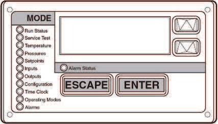
68 Controls Microprocessor The ComfortLink microprocessor controls overall unit operation. Its central executive routine controls a number of processes simultaneously. These include internal timers, reading inputs, analog to digital conversions, fan control, display control, diagnostic control, output relay control, demand limit, capacity control, head pressure control, and temperature reset. Some processes are updated almost continuously, others every to seconds, and some every seconds. The microprocessor routine is started by switching the Emergency ONOFF circuit breaker switch (switch ) to ON position. When the unit receives a call for cooling (either from the internal control or CCN network command), the unit stages up in capacity to maintain the cooler fluid set point. The first compressor starts 11/ to minutes after the call for cooling. The lead circuit can be specifically designated or randomly selected by the controls, depending on how the unit is field configured. A field configuration is also available to determine if the unit should stage up both circuits equally or load one circuit completely before bringing on the other. The ComfortLink microprocessor controls the capacity of the chiller by cycling compressors on and off at a rate to satisfy actual dynamic load conditions. The control maintains leavingfluid temperature set point shown on scrolling marquee display board through intelligent cycling of compressors. Accuracy depends on loop volume, loop flow rate, load, outdoorair temperature, number of stages, and particular stage being cycled off. No adjustment for cooling range or cooler flow rate is required, because the control automatically compensates for cooling range by measuring both returnfluid temperature and leavingfluid temperature. This is referred to as leavingfluid temperature control with returnfluid temperature compensation. The basic logic for determining when to add or remove a stage is a time band integration of deviation from set point plus rate of change of leavingfluid temperature. When leavingfluid temperature is close to set point and slowly moving closer, logic prevents addition of another stage. If leavingfluid temperature is less than 4 F (1.1 C) for water, or F (. C) below the set point for brine units, the unit is shut off until the fluid temperature goes to 4 F (1.1 C) or to F (. C) above the set point to protect against freezing. If 1 F per minute (0. C per minute) pulldown control has been selected (factory setting), no additional steps of capacity are added as long as difference between leavingfluid temperature and set point is greater than 4 F (. C) and rate of change in leavingfluid temperature is less than 1 F per minute (0. C per minute). If it has been less than 90 seconds since the last capacity change, compressors will continue to run unless a safety device trips. This prevents rapid cycling and also helps return oil during short on periods. Lead/lag operation can be configured to balance compressor operating hours when set to automatic. When lead/lag operation is configured to automatic, a compressor wear factor is used to determine which circuit to start first by utilizing a combination of actual run hours and number of starts. Lag compressors in a circuit would also be started to maintain even wear factors. Either circuit can be set to always lead, if desired. The control also performs other special functions when turning on or off. When a circuit is to be turned off, EXV is closed first, and compressor is run until conditions are met to terminate pumpoutto remove refrigerant that was in the cooler. At startup, if a circuit has not run in the last minutes, circuit is run to remove any refrigerant that has migrated to the cooler. The oil pressure switch is bypassed for minutes during startup and for 1 minute during normal operation. Thermistors Eight thermistors are used for temperaturesensing inputs to microprocessor. (A ninth [T9] and/or tenth [T10] may be used as a remote temperature sensor for optional LCWT reset.) T1 leaving chilled fluid temperature T entering fluid (return) temperature T Saturated condensing temperature Circuit A T4 Saturated condensing temperature Circuit B T5 saturation temperature Circuit A T saturation temperature Circuit B T7 Return gas temperature entering compressor cylinder Circuit A T8 Return gas temperature entering compressor cylinder Circuit B T9 Outdoor air temperature sensor (accessory) T10 Remote space temperature sensor (accessory) The microprocessor uses these temperatures to control capacity, fan cycling, and EXV operation. Electronic expansion valve (EXV) To control flow of refrigerant for different operating conditions, EXV piston moves up and down over slot orifices through which refrigerant flows to modulate size of opening. Piston is moved by a stepper motor through 1 discrete steps. The piston is repositioned by the microprocessor every seconds as required. The EXV is used to control superheat in compressor. The difference between thermistors (compressor return gas temperature minus cooler saturation temperature) is used to determine superheat. The EXV is controlled to maintain superheat entering pistons at approximately 9 F (1.1 C), which results in slightly superheated refrigerant leaving cooler. The electronic control provides for a prepurge and pumpout cycle each time the lead compressor in a circuit is started or stopped. These pumpout cycles minimize amount of excess refrigerant that can go to compressor on startup and cause oil dilution (which would result in eventual bearing wear). The microprocessor software is programmed so that EXV functions as an MOP (maximum operating pressure) valve, limiting the suction temperatures to 55 F (1.8 C). This makes it possible to start unit at high fluid temperatures, up to 95 F (5 C), without overloading compressor. Another feature that is factory set (can be reconfigured in the field) limits rate of pulldown to 1 F (0. C) per minute, thereby reducing the demand on startup.
69 Controls (cont) Accessory controls Demand can be further limited by keeping a selected number of compressors from turning on by utilizing demand limit control (the Energy Management Module is required for this function). This FIOP/accessory interfaces with microprocessor to control unit so that chiller s demand does not exceed its setting. It is activated from an external switch. The standard ComfortLink control is programmed to accept various accessory temperature reset options (based on returnfluid temperature, outdoorair temperature, or space temperature), that reset the LCWT. An accessory thermistor (T9 or T10) is required if outdoorair temperature or space temperature reset is selected. The Energy Management Module (EMM) is only required for temperature reset that is initiated by a 4 to 0 ma signal. Ground current protection The and 070 ( Hz) sizes have ground current protection that shuts off compressor(s) if a to amp ground current is sensed by a toroid around the compressor power leads. GTN,GTR ComfortLink controls with Scrolling Marquee display module A standard fourdigit alphanumeric display shows all of the ComfortLink control codes (with expandable clear language), plus set points, time of day, temperatures, pressures, and superheat. Additional information can be displayed all at once with the Navigator display. Control sequence Off cycle During unit off cycle, crankcase heater is energized. If ambient temperature is below F ( C), cooler heaters (if equipped) are also energized. Electronic expansion valves are closed. Startup After control circuit switches on, prestart process takes place, then microprocessor checks itself and waits for temperature to stabilize. First circuit to start may be A or B (automatic lead/lag feature). The controlled pulldown feature limits compressor loading on startup to reduce demand on startup and unnecessary compressor usage. The microprocessor limits supplyfluid temperature decrease (startup only) to 1 F (0. C) per minute. Capacity control On first call for cooling, microprocessor starts initial compressor and fan stage on lead circuit. The EXV remains closed, permitting a pumpouton startup. After pumpout, the valves open and, if necessary, additional outdoor fans are energized. Crankcase heaters are deenergizedwhen a compressor is started. As additional cooling is required, lag circuit starts. If further cooling is needed, compressors are added, alternating between lead and lag circuits. Speed at which capacity is added or decreased is controlled by temperature deviation from set point and rate of temperature change of chilled fluid. As less cooling is required, circuits shut down (or unload) in an order that balances each circuit s compressor run time (depending upon configuration). When no further cooling is called for (in each compressor circuit), EXV closes and compressor and fans continue to run while pumping down cooler. Control features Lowtemperature override This feature prevents LCWT from overshooting the set point and possibly causing a nuisance tripout by the freeze protection. Hightemperature override This feature allows chiller to add capacity quickly during rapid load variations. Demand limit If applied, limits the total power draw of unit to selected point by controlling number of operational compressors during periods of peak electrical demand. The Energy Management Module is required for either stage or 4 to 0 ma demand limit. Temperature reset If applied, microprocessor compares either return fluid, space temperature, or outdoorair temperature with the accessory board settings, and adjusts LCWT appropriately. The Energy Management Module can also be added for 4 to 0 ma reset. Electronic expansion valve and condenserfan control The EXV opens and closes on signal from microprocessor to maintain an approximate 9 F (1 C) refrigerant superheat entering the compressor cylinders. (The compressor motor increases the refrigerant superheat from the approximate 5 F [ C] leaving the cooler to that entering the cylinders.) Condenser fans (operated by microprocessor) run to as low an ambient as possible to maintain a minimum EXV pressure differential. Abnormal conditions All control safeties in chiller operate through compressor protection board or control relay and microprocessor. Highpressure switch directly shuts down compressor(s) through compressor protection board or control relay. For other safeties, microprocessor makes appropriate decision to shut down a compressor due to a safety trip or bad sensor reading and displays appropriate failure code on the display. Chiller holds in safety mode until reset. It then reverts to normal control when unit is reset. Oil pressure safety Safety cuts out if pressure differential is below minimum (accessory on sizes 0070). Safety is bypassed on startup for minutes. Lossofcharge safety Safety cuts out if system pressure drops below minimum. Highpressure cutout Switch shuts down compressors if compressor discharge pressure increases to 4 psig (918 kpa). Ground current safety Safety opens on sensing a currenttoground in compressor windings in excess of.5 amps. Compressor anticycling This feature limits compressor cycling. Loss of flow protection Additional protection is provided by temperature differences between entering and leaving fluid temperature sensors if cooler temperature drops to 4 F (1.1 C). Proof of flow switches are recommended. Sensor failures Failures are detected by the microprocessor. 7
70 Controls (cont) Diagnostics Microprocessor may be put through service test (see Controls, StartUp, Operation, Service and Troubleshooting literature) without additional equipment or tools. Service test confirms microprocessor is functional, informs observer through display the condition of each sensor and switch in chiller, and allows observer to check for proper operation of fans and compressor(s). Default settings To facilitate quick startups, all GTN,GTR chillers with ComfortLink controls are preconfigured with a default setting that assumes standalone operation supplying 44 F (.7 C) chilled water. Configuration setting will be based on any options or accessories included with the unit at the time of manufacturing. Date and time and will need reconfiguring based on location and local time zone. If operation based on occupancy scheduling is desired, this will also need to be set during installation. 8
71 Typical piping and wiring GTN010 9
72 Typical piping and wiring GTN40 NOTES: 1. Chiller must be installed level to maintain proper compressor oil return.. Wiring and piping shown are general pointsofconnection guides only and are not intended for a specific installation. Wiring and piping shown are for a quick overview of system and are not in accordance with recognized standards.. All wiring must comply with applicable local and national codes. 4. All piping must follow standard piping techniques. Refer to Carrier System Design Manual or appropriate ASHRAE (American Society of Heating, Refrigeration, and Air Conditioning Engineers) handbook for details. 5. See Application Data section on page 44 for minimum system fluid volume. This may require the addition of a holding tank to ensure adequate volume. 70
73 Guide specifications HVAC Guide Specifications Reciprocating AirCooled Liquid Chiller Size Range: to 410 Tons (179 to 1445 ) Nominal Carrier Model Number: GTN, GTR Part 1 General 1.01 SYSTEM DESCRIPTION Easytouse, microprocessorcontrolled aircooled liquid chiller utilizing reciprocating compressors and longstroke electronic expansion valves. 1.0 QUALITY ASSURANCE A. Unit shall be rated in accordance with ARI Standard 5/59098 (U.S.A.). B. Unit construction shall be designed to conform to ASHRAE latest revision safety standard and ASME (U.S.A.) applicable codes. C. Unit shall be manufactured in a facility registered to ISO 9001:008(International Standards Organization) manufacturing quality standard. D. Unit operation shall be fully tested at the factory. 1.0 DELIVERY, STORAGE, AND HANDLING A. Unit shall be stored and handled per unit manufacturer s recommendations. B. Unit controls shall be capable of withstanding 0 F ( C) storage temperature in the control compartment for an indefinite period of time. Part Products.01 EQUIPMENT A. General: Factoryassembled, single piece, aircooled liquid chiller. Contained within the unit cabinet shall be all factory wiring, piping, controls, refrigerant charge (R) and special features required prior to field startup. B. Unit Cabinet: 1. Frame shall be of heavygage galvanized steel members.. Cabinet shall be galvanized steel casing with a prepainted finish.. Cabinet shall be capable of withstanding hour salt spray test in accordance with the ASTM B117 standard. C. Fans: Condenser fans shall be directdriven propeller type discharging air vertically upward and shall be equipped with the following features: 1. Permanently lubricated bearings.. Steel wire safety guards coated with PVC.. Statically and dynamically balanced fan blades. D. Compressors: 1. Reciprocating semihermetic type only.. Each equipped with an automatically reversible oil pump, operating oil charge, suction and discharge shutoff valves, and an inserttype factorysized crankcase heater to control oil dilution.. Each mounted on spring vibration isolators with an isolation efficiency of no less than 95%. 4. Speed shall not exceed 17 rpm (9. r/s). 5. Cycles per hour per compressor shall not exceed E. : 1. Shellandtube type with removable heads.. Tubes shall be internally enhanced seamlesscopper type rolled into tube sheets.. Equipped with victaulictype fluid connections. 4. Shell shall be insulated with 1in. (5mm) PVC foam (closedcell) with a maximum K factor of Design shall incorporate independent directexpansion refrigerant circuits.. shall be tested and stamped in accordance with ASME Code for a refrigerant working side pressure of 78 psig (191 kpa). shall have a maximum fluidside pressure of psig (08 kpa). F. Condenser: 1. Coil shall be aircooled with integral subcooler, constructed of aluminum fins mechanically bonded to seamless copper tubes which are then cleaned, dehydrated, and sealed.. Aircooled condenser coils shall be leak tested at 0 psig (104 kpa) and pressure tested at psig (10 kpa). G. Refrigeration Components: Refrigerant circuit components shall include hot gas muffler, high side pressure switch, liquid line shutoff valves, suction and discharge shutoff valves, filter drier, moistureindicating sight glass, stepper motor actuated electronic expansion valve (EXV), and complete operating charge of refrigerant R and compressor oil. H. Controls, Safeties, and Diagnostics: 1. Controls: a. Unit controls shall include the following minimum components: 1) Microprocessor. ) Power and control circuit terminal blocks. ) ON/OFF control switch. 4) Replaceable solidstate relay panel. 5) Clear language, expandable, alphanumeric diagnostic display/set point panel. ) Thermistor installed to measure saturated condensing temperature, cooler saturation temperature, compressor return gas temperature, and cooler entering and leaving fluid temperatures. b. Unit controls shall be capable of performing the following functions: 1) Automatic circuit lead/lag (accessory required for 00, 070 sizes). ) Pump out at beginning and end of every circuit cycle. 71
74 Guide specifications ) Capacity control based on leaving chilled fluid temperature and compensated by rate of change of returnfluid temperature. 4) Limiting of the chilled fluid temperature pull down rate at startup to 1 F (0.5 C) per minute to prevent excessive demand spikes (charges) at startup. 5) Sevenday time schedule. ) Leaving chilled fluid temperature reset from return fluid, outdoor air temperature, space temperature, or 4 to 0 ma input. 7) Demand limit control with stage control (0 to % each) or through 4 to 0 ma input (0 to %).. Safeties: a. Unit shall be equipped with thermistors and all necessary components in conjunction with the control system to provide the unit with the following protections: 1) Loss of refrigerant charge protection. ) Low fluid flow detection. ) Low chilled fluid temperature protection. 4) Low and high superheat protection. 5) Low control voltage (to unit) protection. ) High pressure switch. 7) Low oil pressure protection for each compressor circuit (sizes 08040). 8) Ground current compressor protection (sizes and 070, Hz). b. Compressors shall be equipped with the following manualreset type protections: 1) Pressure overload. ) Electrical overload through the use of definitepurpose contactors and calibrated, ambient compensated, magnetic trip circuit breakers. Circuit breakers shall open all phases in the event of an overload in any one phase (singlephasing condition). c. Fan motors shall have inherent overcurrent protection.. Diagnostics: a. The diagnostic display module shall be capable of indicating the safety lockout condition by displaying a code for which an explanation may be scrolled at the display. Information included for display shall be: 1) Compressor lockout. ) Loss of charge. ) Low fluid flow. 4) Low oil pressure. 5) freeze protection. ) High or low suction superheat. 7) Thermistor malfunction. 8) Entering and leaving fluid temperature. 9) Evaporator and condenser pressure. 10) Electronic expansion valve positions. 11) All set points. 1) Time of day. b. Display module, in conjunction with the microprocessor, must also be capable of displaying the output (results) of a service test. Service test shall verify operation of every switch, thermistor, fan, and compressor before chiller is started. I. Operating Characteristics: 1. Unit shall be capable of starting and running fully loaded at outdoor ambient temperatures from 0 F to 15 F (18 to 5 C), without special controls.. Unit shall be capable of starting up with 95 F (5 C) entering fluid temperature to the cooler.. Multistep cooling capacity control shall be accomplished through the use of unloaders and compressor staging. 4. Two refrigerant circuits shall be provided to protect against loss of total capacity. 5. Unit shall have automatic lead/lag feature to automatically alternate the lead circuit to ensure even compressor wear. J. Motors: 1. Compressor motors shall be cooled by suction gas passing around motor windings.. Condenser fan motors shall be phase type with permanently lubricated bearings and Class F insulation.. Fan motors are totally enclosed, airover (TEAO) type in accordance with IP55 ( Hz only). K. Electrical Requirements: 1. Unit primary electrical power supply (phase) shall be connected to a single location.. Unit control power (singlephase) shall be connected to a separate entry point.. Unit shall be shipped with factory control and power wiring installed. L. Special Features: Certain standard features are not applicable when the features designated by * are specified. For assistance in amending the specifications, your local Carrier Sales Office should be contacted. * 1. Heater: Optional factoryinstalled heater shall protect cooler to 0 F (9 C). *. Optional Condenser Coil Materials: a. PreCoated Aluminum Fin Coils (Gold fin): Shall have epoxy and polyurethane pretreated aluminum fins (gold fin). b. CopperFin Coils: Shall be constructed of copper fins mechanically bonded to copper tubes. All copper construction shall provide protection in moderate coastal applications. c. PostCoated Aluminum Fin Coils (Blygold PoluAL): Shall have a Blygold PoluAL coating (Aluminum hydroxide, 5 microns thickness) uniformly applied to all coil surface. Coated coil shall withstand,000hour salt spray in accordance 7
75 Guide specifications with ASTM (U.S.A.) B117. *. Security Condenser Grilles: A set of metal grilles complete with support retainers and fasteners shall be provided for the protection of the condensing coils, compressors, and cooler. * 4. Part Wind Start: Shall be factory installed to reduce compressor inrush current. 5. Switch: A chilled fluid flow switch shall be fieldinstalled for low fluid flow detection.. Ground current compressor protection: Protection shall be standard with sizes and 070 ( Hz), accessory with all other sizes. 7. Pressure Gages: Unit shall be fieldequipped with suction and discharge pressure gages with manual shutoff valves. 8. Oil Pressure Switch: Unit shall be equipped with an oil pressure safety switch to protect compressor against loss of lubrication (accessory for sizes 00, 070 [0 Hz]; standard on sizes 070 [ Hz] and 08040). * 9. Low Noise Fans: Special condenser fans, motors shall be factory installed allowing fans operate under low noise condition. * 10. High Static Fans: Special condenser fans, motors, and mounts shall be factory installed allowing fans to generate 0.4 in. wg (0.10 kpa) static pressure external to the chiller at nominal condenser airflow (cfm). 11. Compressor Expansion Board: Shall include accessory compressor expansion board for use with multiple compressor unit. * 1. Energy Management Module: Shall be factory or fieldinstalled and capable of 4 to 0 ma leaving fluid temperature reset, cooling set point reset, 4 to 0 ma demand limit, and step demand limit. * 1. Service Option: Shall be factoryinstalled and include Energy Management Module, remote service connection port and handheld expanded display module. * 14. Aluminum Cladding shall be insulated with aluminum cladding as an option. Aluminum cladding can protect cooler insulation against ageing by sunshine and improve esthetic image. *. IP54 Protection Control box is improved in accordance with IP54 protection. 7

76 The Manufacturer reserves the right to change any produt specifications without prior notices Version: Supersede: EFfective Date: CAT_GTN_E105_01 TGTN1100 May, 01
Product Data. Features/Benefits. 30GTN,GTR Air-Cooled Reciprocating Liquid Chillers with ComfortLink controls 50/60 Hz
 Product Data Air-Cooled Reciprocating Liquid Chillers with ComfortLink controls 50/60 Hz Nominal Capacities: 36 to 410 Tons 127 to 1445 Features/Benefits ComfortLink control Your link to a world of simple
Product Data. Features/Benefits. 30GUN,GUR Air-Cooled Reciprocating Liquid Chillers (HFC-134a) with ComfortLink Controls 50/60 Hz
 with ComfortLink Controls 50/60 Hz") Product Data 30GUN,GUR Air-Cooled Reciprocating Liquid Chillers (HFC-134a) with ComfortLink Controls 50/60 Hz Nominal Capacities: 25 to 280 Tons 88 to 985 kw Features/Benefits ComfortLink control Your
Product Data 30GUN,GUR Air-Cooled Reciprocating Liquid Chillers (HFC-134a) with ComfortLink Controls 50/60 Hz Nominal Capacities: 25 to 280 Tons 88 to 985 kw Features/Benefits ComfortLink control Your
Product Data. Features/Benefits
 Product Data 30,,HW Reciprocating Liquid Chillers with COMFORTLINK Controls 50/60 Hz Nominal acities: 30HW 15 to 40 Tons (53 to 141 ) 30 40 to 60 Tons (141 to 210 ) 30 50 and 60 Tons (176 and 210 ) 30,S
Product Data. Features/Benefits. 30GXN,R ECOLOGIC Air-Cooled Chiller with ComfortLink Controls 50/60 Hz. 80 to 450 Tons (267 to 1511 kw)
") Product Data 30GXN,R080-450 ECOLOGIC Air-Cooled Chiller with ComfortLink Controls 50/60 Hz 80 to 450 Tons (267 to 1511 kw) ECOLOGIC 30GXN,R air-cooled chillers are designed from the ground up to meet the
Product Data 30GXN,R080-450 ECOLOGIC Air-Cooled Chiller with ComfortLink Controls 50/60 Hz 80 to 450 Tons (267 to 1511 kw) ECOLOGIC 30GXN,R air-cooled chillers are designed from the ground up to meet the
Co m f o r t Li n k N A V I G A T O R F F
 TIME EWT LWT SETP Co m f o r t Li n k N A V I G A T O R 1 2.58 5 4. 6 F 4 4. 1 F 4 4. 0 F M O D E Alarm Status Run Status Service Test Temperatures Pressures Setpoints Inputs Outputs Configuration Time
Product Data. Features/Benefits. 30HXA HXC Condenserless and Fluid-Cooled Chillers 50/60 Hz. 75 to 265 Tons (264 to 931 kw)
") TIME EWT LWT SETP ComfortLink N A V I G A T O R 12.58 54.6 F 44.1 F 44.0 F M O D E Alarm Status Run Status Service Test Temperatures Pressures Setpoints s Outputs Configuration Time Clock Operating Modes
TIME EWT LWT SETP ComfortLink N A V I G A T O R 12.58 54.6 F 44.1 F 44.0 F M O D E Alarm Status Run Status Service Test Temperatures Pressures Setpoints s Outputs Configuration Time Clock Operating Modes
AIR COOLED CHILLERS WATER COOLED CHILLERS
 AIR COOLED CHILLERS WATER COOLED CHILLERS STANDARD UNIT SPECIFICATIONS OF COMMERCIAL AIR COOLED CHILLERS General Description & Assembly Air Cooled Chillers are commercial packaged systems complete with
Product Data. Features/Benefits 50JS SINGLE-PACKAGED HEAT PUMP 50 HZ UNITS 7 TO 18 KW (2 TO 5 NOMINAL TONS)
") SINGLE-PACKAGED HEAT PUMP 50 HZ UNITS 7 TO 18 KW (2 TO 5 NOMINAL TONS) Product Data UNIT (50 Hz) Single-packaged Heat Pump for Residential and Light Commercial applications. Features/Benefits One-piece
SINGLE-PACKAGED HEAT PUMP 50 HZ UNITS 7 TO 18 KW (2 TO 5 NOMINAL TONS) Product Data UNIT (50 Hz) Single-packaged Heat Pump for Residential and Light Commercial applications. Features/Benefits One-piece
CAS. Product Specifications. COMMERCIAL SPLIT SYSTEMS CONDENSING UNITS R 410A, 6 to 20 TONS BUILT TO LAST, EASY TO INSTALL AND SERVICE
 COMMERCIAL SPLIT SYSTEMS CONDENSING UNITS R 410A, 6 to 20 TONS BUILT TO LAST, EASY TO INSTALL AND SERVICE Single stage cooling capacity control on all 0 241 models Two stage cooling capacity control on
APPENDIX A. Mechanical Equipment Sheets: York Chiller Marley Cooling Towers Calmac IceBank Storage Tanks Low Temp Air Cooling Coils
 APPENDIX A Mechanical Equipment Sheets: York Chiller Marley Cooling Towers Calmac IceBank Storage Tanks Low Temp Air Cooling Coils FORM 201.24-EG3 (1201) YCWS WATER COOLED LIQUID CHILLER HFC-407C 89 TONS
BAC / BHC Product Specifications
 COMMERCIAL AIR HANDLERS (3 PHASE) 6 to 20 TON / Product Specifications REFRIGERATION CIRCUIT Standard factory-installed thermostatic expansion valves (TXVs) on units; units include TXVs and check valves
Air-Cooled Screw Compressor Chiller
 Installation, Operation and Maintenance Manual IOMM ALS Group: Chiller Part Number: 070774401 Date: February 1998 Supersedes: IM 548-3 Air-Cooled Screw Compressor Chiller ALS 070A through 425A 60 Hertz
VLH 504 to Air-to-Water Reverse Cycle Heat Pumps. 126 to 294 kw. 133 to 307 kw
 Air-to-Water Reverse Cycle Heat Pumps VLH 504 to 1204 126 to 294 kw 133 to 307 kw Technical Brochure TM VLH-N.3GB Date : June 2005 Supersedes : TM VLH-N.2GB/07.04 Specifications Advantages Range extension
Product Catalog. NQ Series. Portable and Remote Air-Cooled Condenser Chillers 4 to 43 Tons
 Product Catalog NQ Series Portable and Remote Air-Cooled Condenser Chillers 4 to 43 Tons Page Intentionally Blank Contents Standard Features...1 Available Options...3 Oversized Pumps... 3 High Flow Unit
SeasonPak Packaged Air-Cooled Water Chiller
 Installation Manual IM 676 Group: Chiller Part Number: 594920Y Date: July 1996 Supersedes: None SeasonPak Packaged Air-Cooled Water Chiller Models ALR 032E Through 185E 1996 McQuay International Table
Air-Cooled Liquid Chiller with integrated hydraulic module
 Air-Cooled Liquid Chiller with integrated hydraulic module Cooling only: CGAN 200-250 - 300-400 - 450-490 - 500-600 - 700-800 - 900-925 Reversible: CXAN 200-250 - 300-400 - 450-490 - 500-600 - 700-800
Installation Instructions
 GEMINI SELECT 38APS025-065, 38APD025-130 Air-Cooled Condensing Units with PURON Refrigerant (R-410A) 50/60 Hz Installation Instructions CONTENTS Page SAFETY CONSIDERATIONS...................... 1 INSTALLATION................................
R-22, 13 SEER 60 Hertz
 TECHNICAL GUIDE R-22, 13 SEER 60 Hertz Description These UPG packaged cooling/heating air conditioners are designed for outdoor installation. Only utility and duct connections are required at the point
Product Data. 40RUA 18.3 to 59.2 kw Direct Expansion Packaged Air---Handling Units 50 Hz
 18.3 to 59.2 kw Direct Expansion Packaged Air---Handling Units 50 Hz Product Data 07 --- 12 C09035 Carrier s versatile packaged air-handling units satisfy design requirements with: S Multi-position design
Product Data. Features/Benefits
 Product Data GEMINI SELECT 3APS5-5, 3APD5-13 Commercial Air-Cooled Condensing Units with PURON Refrigerant (R-A) / Hz 5 to 13 Nominal Tons ( to 57 Nominal ) A3-797 - UNIT a3-79 5 UNIT WITH LOW SOUND OPTION
BAC / BHC SERIES 6 to 20 Ton Air Handlers
 / SERIES 6 to 20 Ton Air Handlers COMMERCIAL SPLIT SYSTEM AIR HANDLER FEATURES CONSTRUCTION Die-formed galvanizedsteel casingsprovide durabilityand structuralintegrity. HIGH STATIC DESIGN High static design
BAC / BHC SERIES 6 to 20 Ton Air Handlers
 / SERIES 6 to 20 Ton Air Handlers COMMERCIAL SPLIT SYSTEM AIR HANDLER FEATURES CONSTRUCTION Die-formed galvanizedsteel casingsprovide durabilityand structuralintegrity. HIGH STATIC DESIGN High static design
SLH 1202 to Air-to-Water Reverse Cycle Heat Pumps. With Screw Compressors. 261 to 775 kw. 287 to 853 kw
 Air-to-Water Reverse Cycle Heat Pumps SLH 1202 to 3804 With Screw Compressors 261 to 775 kw 287 to 853 kw Technical Brochure TM SLH-A.2GB Date : November 2004 Supersedes : TM SLH-A.1GB/05.04 Design Features
Product Data PH3Z 13 SEER SINGLE -PACKAGED HEAT PUMP SYSTEM WITH R -22 REFRIGERANT SINGLE AND THREE PHASE 2-5 NOMINAL TONS ( )
") 13 SEER SINGLE -PACKAGED HEAT PUMP SYSTEM WITH R -22 REFRIGERANT SINGLE AND THREE PHASE 2-5 NOMINAL TONS (024-0) Product Data Fig. 1 - Unit 664B Single -Packaged Heat Pump Units with: S easy installation
13 SEER SINGLE -PACKAGED HEAT PUMP SYSTEM WITH R -22 REFRIGERANT SINGLE AND THREE PHASE 2-5 NOMINAL TONS (024-0) Product Data Fig. 1 - Unit 664B Single -Packaged Heat Pump Units with: S easy installation
Product Data. Features/Benefits. OMNIZONE 50XCR06-24 Remote Air-Cooled Indoor Self-Contained Systems with PURON Refrigerant (R-410A)
") Product Data OMNIZONE 50XCR06-24 Remote Air-Cooled Indoor Self-Contained Systems with PURON Refrigerant (R-410A) 5 to 20 Nominal Tons The 50XCR single-package remote aircooled units offer: Compact, durable,
Product Data OMNIZONE 50XCR06-24 Remote Air-Cooled Indoor Self-Contained Systems with PURON Refrigerant (R-410A) 5 to 20 Nominal Tons The 50XCR single-package remote aircooled units offer: Compact, durable,
Product Data. Features/Benefits. 42BH System Fan Coil. 800 to 4000 Cfm
 Product Data 42BH System Fan Coil 800 to 4000 Cfm Satisfy All Your Design Requirements with Carrier s Versatile 42BH Fan Coil Unit A selection of 6 sizes covers capacities from 800 to 4000 cfm Choice of
Product Data. Features/Benefits
 Product Data GEMINI SELECT 38APS025-065, 38APD025-1 Commercial Air-Cooled Condensing Units with PURON Refrigerant (R-410A) /60 Hz 25 to 1 Nominal Tons (88 to 7 Nominal ) A38-7097 0-060 UNIT a38-7096 025
TECHNICAL GUIDE R-410A, 13 SEER LATITUDE SERIES 60 Hertz
 TECHNICAL GUIDE R-410A, 13 SEER LATITUDE SERIES 60 Hertz Description These York Latitude packaged cooling/heating air conditioners are designed for outdoor installation. Only utility and duct connections
Air Cooled Water Chillers. CLS 182 to to 150 kw. Technical Brochure TM CLS-W.3GB Date : October 2004 Supersedes : TM CLS-W.2GB/07.
 Air Cooled Water Chillers CLS 182 to 602 41 to 150 kw Technical Brochure TM CLS-W.3GB Date : October 2004 Supersedes : TM CLS-W.2GB/07.04 R Specifications General characteristics The CLS air cooled water
SINGLE PACKAGE HEAT PUMPS
 SINGLE PACKAGE HEAT PUMPS HPP024 THRU 060 2 THRU 5 NOMINAL TONS 13 SEER FACTORY MOUNTED TXV DESCRIPTION These packaged heat pumps are designed for outdoor installation. Only utility and duct connections
Installation Instructions
 GEMINI SELECT 38APS025-050,38APD025-100 Air-Cooled Condensing Units with PURON Refrigerant (R-410A) 50/60 Hz Installation Instructions CONTENTS Page SAFETY CONSIDERATIONS...................... 1 INSTALLATION................................
Chiller. AQL/AQH 40 to 75. Air Cooled Water Chillers Cooling Only and Heat Pump Engineering Data Manual to 77.2 kw to 75.
 Chiller AQL/ to 75 Air Cooled Water Chillers Only and Heat Pump Engineering Data Manual.0 to 75.8 kw 39.9 to 77.2 kw Outstanding Strength Points R410A Refrigerant. New simpler refrigerant circuit layout.
Product Catalog TSE Series Scroll Central Chillers
 Product Catalog TSE Series Scroll Central Chillers Contents Features...1 Available Options...3 Hot Gas Bypass Valve... 3 Rotary Non-Fused Disconnect Switch... 3 Integral Reservoir and Pumping System...
Product Catalog TSE Series Scroll Central Chillers
 Product Catalog TSE Series Scroll Central Chillers Contents Features...1 Hot Gas Bypass Valve... 2 Rotary Non-Fused Disconnect Switch... 2 Integral Reservoir and Pumping System... 3 Remote Condenser Coil
RTAA Packaged Air Cooled Helical Rotary Liquid Chiller High Ambient (50 & 60 Hz) 125 to 400 Tons
 125 to 400 Tons") RTAA 213-434 Packaged Air Cooled Helical Rotary Liquid Chiller High Ambient (50 & 60 Hz) 125 to 400 Tons C20 CA 603 E Packaged Air Cooled Helical Rotary Liquid Chiller for High Ambient RTAA 213-434 (50
RTAA 213-434 Packaged Air Cooled Helical Rotary Liquid Chiller High Ambient (50 & 60 Hz) 125 to 400 Tons C20 CA 603 E Packaged Air Cooled Helical Rotary Liquid Chiller for High Ambient RTAA 213-434 (50
PROJECT MANUAL GUIDE SPECIFICATIONS FOR: PFANNENBERG SERIES EB COMPACT PACKAGED CHILLERS PART 1 GENERAL
 PROJECT MANUAL GUIDE SPECIFICATIONS FOR: PFANNENBERG SERIES EB COMPACT PACKAGED CHILLERS PART 1 GENERAL 1.1 SUMMARY A. Packaged Chillers offer a self-contained means of producing cooling liquid primarily
ASHRAE 90.1 COMPLIANT PACKAGED ROOFTOP ELECTRIC COOLING UNITS, R 410A, TONS 3 Phase, 50 Hz. BUILT TO LAST, EASY TO INSTALL AND SERVICE
 RAS Product Specifications ASHRAE 90.1 COMPLIANT PACKAGED ROOFTOP ELECTRIC COOLING UNITS, R 410A, 14 20 TONS 3 Phase, 50 Hz. BUILT TO LAST, EASY TO INSTALL AND SERVICE One piece, high efficiency electric
technical sales guide - 60Hz Ducted Split Units HIGH AMBIENT OPERATION 52 UPTO
 technical sales guide - 60Hz Taurus R Ducted Split Units UPTO HIGH AMBIENT OPERATION 52 O C Page CONTENTS Nomenclature.. 2 Description. 3 Features.. 3 Product Data. 4 Condensing Unit Cooling Performance
30GX AIR-COOLED LIQUID CHILLER
 30GX-4SB 30GX080-265 AIR-COOLED LIQUID CHILLER PERFORMANCE DATA FIELD WIRING DIAGRAM 1997 Carrier Corporation Syracuse, New York 13221 Form 30GX-4SB Supersedes 30GX-3SB Printed in U.S.A. 12-97 Catalog
SUBMITTAL COVER SHEET
 SUBMITTAL COVER SHEET PROJECT NAME LOCATION ARCHITECT ENGINEER CONTRACTOR SUBMITTED BY DATE UNIT SUMMARY Quantity Unit Designation Model No. Total Cooling Sensible Cooling Air Ent. Evaporator Air Lvg.
Residential Packaged Geothermal Heat Pump
 ENGIneering Design Guide Residential Packaged Geothermal Heat Pump HP Series 1 1 /2 to 5 Tons Heat Controller, Inc. 1900 Wellworth Ave. Jackson, MI 49203 (517)787-2100 www.heatcontroller.com Engineering
PACKAGED LIQUID CHILLER 6. HUMIDIFIER SECTIONS. C Member. Liquid Chiller. nowlc And noalc Series
 6. HUMIDIFIER SECTIONS Liquid Chiller nowlc And noalc Series C Member 1 Features and Benefits OMRAN cold generator reciprocating Liquid chiller are designed and built to provide reliable,efficient performance
DIRECT EXPANSION COMMERCIAL PACKAGED AIR HANDLING UNITS, 6 25 TONS
 Product Specifications DIRECT EXPANSION COMMERCIAL PACKAGED AIR HANDLING UNITS, 6 25 TONS BUILT TO LAST, EASY TO INSTALL AND SERVICE Multi position design for horizontal or vertical installation without
AIR COOLED WATER CHILLERS. Air Cooled Water Chillers. MALC 040 thru MALC TR thru 490 TR 88 kw thru 1725 kw. R-134a
 AIR COOLED CHILLERS Air Cooled Water Chillers MALC 040 thru MALC 740 25 TR thru 490 TR 88 kw thru 1725 kw R14a 1 AIR COOLED CHILLERS COMPONENTS 2 COMPRESSOR CUTAWAY VIEW AIR COOLED CHILLERS FEATURES/BENEFITS
38AUM Air Cooled Condensing Units 50Hz
 38AUM Air Cooled Condensing Units 50Hz Quality Assurance Certificate Reg. No: 04 100 950420 Product Data Catalog Subject to change without notice Manufacturer s Name: Saudi Airconditioning Manufacturing
RCD Air Cooled Condensing Unit (50/60 Hz)
") Environment friendly Easy to access components More efficient air cooled condenser coils Easy to install and maintain The Saudi Factory for Air Conditioning Units RCD Air Cooled Condensing Unit (50/60
Environment friendly Easy to access components More efficient air cooled condenser coils Easy to install and maintain The Saudi Factory for Air Conditioning Units RCD Air Cooled Condensing Unit (50/60
TSA6. Product Specifications. SmartComfort TXC 5600
 ENVIRONMENTALLY SOUND REFRIGERANT TSA6 SmartComfort TXC 5600 Product Specifications 16 SEER SINGLE STAGE AIR CONDITIONER WITH OBSERVER COMMUNICATING CONTROL SYSTEM 1½ THRU 5 TONS SPLIT SYSTEM 208 / 230
Product Data. Features/Benefits. Omnizone 50XCA06-14 Air-Cooled Indoor Self-Contained Systems with Puron Refrigerant (R-410A) 5 to 12 Nominal Tons
 5 to 12 Nominal Tons") Product Data Omnizone 50XCA06-14 Air-Cooled Indoor Self-Contained Systems with Puron Refrigerant (R-410A) 5 to 1 Nominal Tons The 50XCA single-package cooling units with integral air-cooled condensers
Product Data Omnizone 50XCA06-14 Air-Cooled Indoor Self-Contained Systems with Puron Refrigerant (R-410A) 5 to 1 Nominal Tons The 50XCA single-package cooling units with integral air-cooled condensers
PERFORMANCE DATA TYPICAL FIELD WIRING CERTIFIED DIMENSION PRINTS CERTIFIED ROOF CURB DIMENSION PRINTS
 50FP-1SB 50FP034, 038, 044, 048, 054, 064, 074 SINGLE-PACKAGE COOLING UNITS CONSTANT/VARIABLE VOLUME PRODUCT INTEGRATED CONTROLS CARRIER COMFORT NETWORK COMPATIBLE FACTORY-INSTALLED OPTIONAL ELECTRIC HEAT
Product Data PH13NAZ. DUCTED HEAT PUMP Sizes 018 To To 5 Nominal Tons INDUSTRY LEADING FEATURES / BENEFITS
 DUCTED HEAT PUMP Sizes 018 To 060 1.5 To 5 Nominal Tons Product Data A08379 INDUSTRY LEADING FEATURES / BENEFITS Energy Efficiency S Sound S Levels as low as 71 dba Design Features S New aesthetics S Small
Package Air Conditioners
 MODEL: RACA14 Package Air Conditioners FORM NO. SSC-969 REV. 1 Sure Comfort RACA14 Package Air Conditioners RACA14 14 SEER Nominal Sizes 2-5 Tons [7.0-17.6 kw] Proper sizing and installation of equipment
SUBMITTAL COVER SHEET
 SUBMITTAL COVER SHEET PROJECT NAME LOCATION ARCHITECT ENGINEER CONTRACTOR SUBMITTED BY DATE UNIT SUMMARY Quantity Unit Designation Model No. Total Cooling Sensible Cooling Air Ent. Evaporator Air Lvg.
III. Roof Mount AC Mobile Climate Control 19 MCC Reference Manual 2014
 III. Roof Mount AC Mobile Climate Control 19 MCC Reference Manual 2014 III.1. Large Roof Mount PN: 89-3037 Roof Mount Unit Eco 136 Parallel roof mount Air-conditioning and ventilation systems The Eco 136
Product Data. Features/Benefits. 38HDL Cooling Only Condensing Unit. 1 1 / 2 to 5 Nominal Tons
 Product Data 38HDL018-060 Cooling Only Condensing Unit 1 1 / 2 to 5 Nominal Tons The 38HDL energy-efficient condensing unit incorporates innovative technology to provide reliable cooling performance. Built
D M S 760 C01 A A 1 1
 CONTENTS Description Features Options Available Selection Method Product Data Cooling Performance Data (85 F Ambient Cooling Performance Data (95 F Ambient) Cooling Performance Data (105 F Ambient)..............................
SUNLINE 2000 SPLIT-SYSTEM AIR-COOLED CONDENSING UNITS 50 AND 60 HZ DESCRIPTION FEATURES
 (791) SPLIT-SYSTEM AIR-COOLED CONDENSING UNITS 50 AND 60 HZ H1CE180 & 240 15 AND 20 NOMINAL TONS (60 HZ) 13 AND 17-1/2 NOMINAL TONS (50 HZ) SUNLINE 2000 DESCRIPTION These Sunline 2000 units are completely
TECHNICAL GUIDE DESCRIPTION MODELS: D4HH 024 THRU 180 HORIZONTAL FEATURES SINGLE PACKAGE AIR CONDITIONERS HORIZONTAL INDOOR & CONDENSER AIR FLOW
 DESCRIPTION TECHNICAL GUIDE SINGLE PACKAGE AIR CONDITIONERS HORIZONTAL INDOOR & CONDENSER AIR FLOW MODELS: D4HH 024 THRU 180 York horizontal ductable air conditioning packages offer a complete line of
Installation Instructions
 Gemini Select 38APS025-065, 38APD025-130 Air-Cooled Condensing Units with Puron Refrigerant (R-410A) 50/60 Hz Installation Instructions CONTENTS Page SAFETY CONSIDERATIONS...................... 1 STORAGE
AQVSL/AQVSH STAR 85 to 140
 Chiller QVSL/ STR 85 to 140 ir Cooled Water Chillers Cooling Only and Heat Pump Engineering Data Manual 82 to 157 kw 83 to 168 kw Outstanding Strength Points Units with R410 refrigerant (it will be the
Q6SP Series Rev A TECHNICAL SPECIFICATIONS. FEATURES and BENEFITS. 7.5 and 10 Ton Packaged Electric Heat Pump Units with R-410A 11.
 TECHNICAL SPECIFICATIONS Q6SP Series Rev A 7.5 and 10 Ton Packaged Electric Heat Pump Units with R-410A 11.0 EER Commercial Systems Meet or Exceed ASHRAE 90.1-2010 These 7½ and 10 ton units are designed
EFFICIENCY 17 SEER TWO STAGE AIR CONDITIONER WITH OBSERVER
 ENVIRONMENTALLY SOUND REFRIGERANT HCA7 QuietComfort DXT+ Product Specifications HIGH EFFICIENCY 17 SEER TWO STAGE AIR CONDITIONER WITH OBSERVER COMMUNICATING CONTROL SYSTEM 2 THRU 5 TONS SPLIT SYSTEM 208/230
CAS. Product Specifications
 CAS Product Specifications COMMERCIAL SPLIT SYSTEMS CONDENSING UNITS R 410A, 6 to 20 TONS BUILT TO LAST, EASY TO INSTALL AND SERVICE Single stage cooling capacity control on all 0 to 241 models Two stage
YCWL WATER-COOLED SCROLL LIQUID CHILLER
 FORM 201.26-EG1 (1007) YCWL WATER-COOLED SCROLL LIQUID CHILLER 50 THROUGH 150 TONS 175kW THROUGH 530 kw 60Hz STYLE A TABLE OF CONTENTS FORM 150.26-EG1 (507)... 1 Introduction... 3 Specification... 4 Microprocessor
TECHNICAL GUIDE GENERAL SPECIFICATIONS COMMERCIAL SPLIT-SYSTEM COOLING UNITS FOUR PIPE SYSTEM OUTDOOR UNIT:
 036-21323-001-B-0202 GENERAL SPECIFICATIONS OUTDOOR UNIT: Two independent refrigerant circuits Inherently protected fan motors Two independent scroll compressors V-Coil Design Exterior service port connections
Installation, Start-Up and Service Instructions
 Installation, Start-Up and Service Instructions 48AJ,AK,AW,AY020-060 with Reciprocating Compressor 48EJ,EK,EW,EY024-068 Single Package Rooftop Units Electric Cooling/Gas Heating CONTENTS Page SAFETY CONSIDERATIONS......................
FC SERIES FLUID COOLERS THE LEADER IN THE INDUSTRY FOR ALL YOUR HVAC NEEDS. Replacement Coils Heat Exchangers Fan Coils
 FC SERIES FLUID COOLERS THE LEADER IN THE INDUSTRY FOR ALL YOUR HVAC NEEDS. Replacement Coils Heat Exchangers Fan Coils Phone: 484-498-8660 Fax: 484-631-0558 www.capitalcoil.com sales@capitalcoil.com FAN
30GX AIR-COOLED LIQUID CHILLER
 30GX-5SB 30GX080-265 AIR-COOLED LIQUID CHILLER PERFORMANCE DATA FIELD WIRING DIAGRAM 1998 Carrier Corporation Syracuse, New York 13221 Form 30GX-5SB Supersedes 30GX-4SB Printed in U.S.A. 5-98 Catalog No.
R4A5. Product Specifications EFFICIENT 14 SEER/ EER AIR CONDITIONER ENVIRONMENTALLY SOUND R 410A REFRIGERANT
 ENVIRONMENTALLY SOUND REFRIGERANT R4A5 Product Specifications EFFICIENT 14 SEER/11.7 12.2 EER AIR CONDITIONER ENVIRONMENTALLY SOUND R 410A REFRIGERANT 1 1/2 THRU 5 TONS SPLIT SYSTEM 208/230 Volt, 1 phase,
SCROLL - AIR COOLED PACKAGED & SPLIT SYSTEM ICE CHILLERS
 SCROLL - AIR COOLED PACKAGED & SPLIT SYSTEM ICE CHILLERS 1 to 40 Nominal Tons Rev-01 TABLE OF CONTENTS Page: Description 3 4 5 6 7 8 9 10 11 12 13 14 15 16 17 18 19 20 Product Nomenclature Air Cooled Chiller
N4A6. Product Specifications
 ENVIRONMENTALLY SOUND REFRIGERANT N4A6 Product Specifications EFFICIENT UP TO 16.5 SEER/12.2 13.0 EER AIR CONDITIONER ENVIRONMENTALLY SOUND R 410A REFRIGERANT 1 1/2 THRU 5 TONS SPLIT SYSTEM 208/2 Volt,
Product Data. Features/Benefits. WEATHERMASTER 36S Water Control Induction Air Terminals to cfm (1770 to 8900 Btuh)
") Product Data WEATHERMASTER 36S Water Control Induction Air Terminals 19.4 to 131.9 cfm (1770 to 8900 Btuh) Induction air terminals offer: Heating and cooling operation 2-pipe or 4-pipe system options Automatic
Product Data WEATHERMASTER 36S Water Control Induction Air Terminals 19.4 to 131.9 cfm (1770 to 8900 Btuh) Induction air terminals offer: Heating and cooling operation 2-pipe or 4-pipe system options Automatic
TSTAT0201CW (Sold Separately) Qualifying models only. Max. Fuse or Breaker
 Qualifying models only. Max. Fuse or Breaker") HVA9 Product Specifications HIGH EFFICIENCY UP TO 19 SEER VARIABLE SPEED AIR CONDITIONER WITH OBSERVER COMMUNICATING CONTROL SYSTEM 2 THRU 5 TONS SPLIT SYSTEM 208 230 Volt, 1 phase, 60 Hz REFRIGERATION
HVA9 Product Specifications HIGH EFFICIENCY UP TO 19 SEER VARIABLE SPEED AIR CONDITIONER WITH OBSERVER COMMUNICATING CONTROL SYSTEM 2 THRU 5 TONS SPLIT SYSTEM 208 230 Volt, 1 phase, 60 Hz REFRIGERATION
ËÕߪ Õ» ç åé. 50BY/BL Series. Single-Package Cooling Units 90, ,500 BTUH. World's No.1 Air Conditioning Expert
 ËÕߪ Õ» ç åé BY/BL Series Single-Package Cooling Units 90,000-895,0 BTUH World's No.1 Air Conditioning Expert www.carrier.co.th BY/BL Series Features Commercial or Industrial Applications Single- or Multiple-Unit
VLS (Cooling Only) VLH (Heat Pump Version) VLR (Total Heat Recovery Version)
 VLH (Heat Pump Version) VLR (Total Heat Recovery Version)") R u Air Cooled Water Chillers VLS (Cooling Only) VLH (Heat Pump Version) VLR (Total Heat Recovery Version) Models 524 to 1204 137 to 308 kw 150 to 336 kw Engineering Data Manual EDM VL410-W.2GB Date :
R u Air Cooled Water Chillers VLS (Cooling Only) VLH (Heat Pump Version) VLR (Total Heat Recovery Version) Models 524 to 1204 137 to 308 kw 150 to 336 kw Engineering Data Manual EDM VL410-W.2GB Date :
CAS. Product Specifications
 CAS Product Specifications COMMERCIAL SPLIT SYSTEMS CONDENSING UNITS R 410A, 6 to 20 TONS BUILT TO LAST, EASY TO INSTALL AND SERVICE Single stage cooling capacity control on all 0 to 150 models Terminal
(Thin) (Ultrathin) Suspended Air-handling Unit
 (Ultrathin) Suspended Air-handling Unit") (Thin) (Ultrathin) Suspended Air-handling Carrier China Headquartered in Farmington, Connecticut, USA, Carrier Corporation is the world's largest provider of heating, air conditioning and refrigeration
(Thin) (Ultrathin) Suspended Air-handling Carrier China Headquartered in Farmington, Connecticut, USA, Carrier Corporation is the world's largest provider of heating, air conditioning and refrigeration
Conquest air-cooled chillers and heat pumps
 Conquest air-cooled chillers and heat pumps Scroll compressor Model / 42-160 kw CG-PRC026A-E4 Introduction Trane is a leader in the air-cooled chillers marketplace, thanks to excellence in design and manufacturing.
SPLIT SYSTEM COOLING 2, 3, 4 & 5 TON ALLEGIANCE 16 MODELS 4A7A6024,036,048 & 060B American Standard Inc. All Rights Reserved
 SPLIT SYSTEM COOLING 2, 3, 4 & 5 TON ALLEGIANCE 16 MODELS 4A7A6024,036,048 & 060B 2005 American Standard Inc. All Rights Reserved PUB. NO. 12-1200-02 March 2005 Features and Benefits Duration staged scroll
ACS Screw Water Chiller R-134a
 ACS Screw Water Chiller R-134a 45-430 TR 158-1512 kw COMMERCIAL AND INDUSTRIAL AIR COOLED SCREW CHILLER 50 Hz For more technical information please visit Table of Contents INTRODUCTION NOMENCLATURE OUT
CSA6. Product Specifications. SoftSound SXC 2600
 16 SEER SINGLE STAGE AIR CONDITIONER WITH OBSERVERr COMMUNICATING CONTROL SYSTEM 1½ THRU 5 TONS SPLIT SYSTEM 208 / 2 Volt, 1- phase, 60 Hz REFRIGERATION CIRCUIT S Copeland Scroll compressors on all models
Installation, Start-Up and Service Instructions
 Installation, Start-Up and Service Instructions CONTENTS Page SAFETY CONSIDERATIONS.....................1,2 INSTALLATION................................ 2-31 Step 1 Complete Pre-Installation Checks.........................................
Product Data. 40RUA/40RUS 6to30TonDirectExpansion 7.5to30TonChilledWater Packaged Air- Handling Units FEATURES/BENEFITS
 / 6toTonDirectExpansion 7.5toTonChilledWater Packaged Air- Handling Units Product Data 40RU07-40RU - C09035 C09036 Carrier s versatile packaged air-handling units satisfy design requirements with: S Multi-
AIR-COOLED SCROLL CHILLERS STYLE E
 FORM 150.67-EG1 (1206) AIR-COOLED SCROLL CHILLERS STYLE E Dual Circuit single circuit R-410a YCAL0019 YCAL0066 50 and 60Hz 15 65 TON 53 218 kw Table of Contents Introduction...3 Specification...4 Options
Low Air Process Room. Chiller Series. EPC - High & Medium Temperature Application Capacity: 2.2kW to 19.2kW
 G4 Low Air Process Room Chiller Series EPC - High & Medium Temperature Application Capacity: 2.2kW to 19.2kW DEPC - High & Medium Temperature Application Dual Air Throw Capacity: 4.4kW to 38.4kW Low Noise
SPLIT SYSTEM COOLING 2½, 3, 4 & 5 TON ALLEGIANCE 18 MODELS 2A7A8030, 036, 048 & 060B American Standard Inc. All Rights Reserved
 SPLIT SYSTEM COOLING 2½, 3, 4 & 5 TON ALLEGIANCE 18 MODELS 2A7A8030, 036, 048 & 060B 2005 American Standard Inc. All Rights Reserved PUB. NO. 12-1194-02 February 2005 Features and Benefits Two Duration
PACKAGE AIR CONDITIONERS
 PACKAGE AIR CONDITIONERS FORM NO. S22-92 REV. 2 Supersedes Form No. S22-92 Rev. RLNA- SUPER HIGH EFFICIENCY SERIES NOMINAL SIZES -5 TONS [0.6-7.6 kw] *Unit shown with optional louver panels installed..0
Contents. Carrier China
 42CE Fan Coil Unit Carrier China Headquartered in Farmington, Connecticut, USA, Carrier Corporation is the world's largest provider of heating, air conditioning and refrigeration solutions, with operations
N2AE - 50 Hz PRODUCT SPECIFICATIONS
 ISO 9001:2000 REGISTERED N2AE - 50 Hz PRODUCT SPECIFICATIONS 50 Hz AIR CONDITIONING CONDENSING UNIT 230 Volt, 1-phase, 50 Hz in 1½, 2, 2½, 3, 4 tons 400 Volt, 3-phase, 50 Hz in 3, 3½, 4, 5 tons REFRIGERATION
Appendix A. Cooling Coil
 Appendix A COILS FOR RUN-AROUND HEAT RECOVERY SYSTEM Cooling Coil Model number D--B45 Coil Information Tag Exhaust Wint Actual airflow Quantity System type 1 Chilled Water Entering dry bulb Entering wet
MODEL YCWL WATER-COOLED SCROLL LIQUID CHILLER STYLE A
 MODEL YCWL WATER-COOLED SCROLL LIQUID CHILLER STYLE A 50 200 TONS 175kW 700 kw 60Hz Nomenclature YCWL 0084 S E 46 X A A UNIT TYPE YORK Water Cooled Scroll Compressor MODEL # 0056 0300 0064 0301 0074 0345
Product Data. Features/Benefits. 38AK AKS with 40RM Commercial Air-Cooled Split Systems 50 Hz
 Product Data 38AK007-012 38AKS008-044 with 007-034 Commercial Air-Cooled Split Systems 50 Hz Nominal: 19.0 to 127.0 kw (5.3 to 35.8 Tons) 38AKS013-024 38AK007,008,012 38AKS008,009,012 Features/Benefits
ODYSSEY Product Catalogue Light Commercial Split System 5-20 Tons TTA/TTH/TWE Models 50 Hz
 ODYSSEY Product Catalogue Light Commercial Split System 5-20 Tons TTA/TTH/TWE Models 50 Hz Condensing Models TTK 060 KD TTA 075 RD TTA 100 RD TTA 120 RD TTA 150 RD TTA 180 RD TTA 200 RD TTA 240 RD Air
Landmark Rooftop Packaged Units
 Landmark Rooftop Packaged Units Engineered for superior performance and reliability Exclusively distributed by AUS - 13 23 50 www.lennoxaus.com.au NZ - 0800 653 330 www.lennoxnz.co.nz 1 Landmark Rooftop
PH120. Rooftop Packaged. R410a Refrigerant PERFORMANCE DATA OUTDOOR COIL ENTERING TEMPERATURE 0 C
 PH120 R410a Refrigerant Rooftop Packaged INDOOR COIL ENTERING AIR TEMP 0 c DB WB 21 23 25 27 29 31 PERFORMANCE DATA OUTDOOR COIL ENTERING TEMPERATURE 0 C 30 35 40 45 Cap Cap Cap Cap 17 115.3 70.7 11.5
Table of Contents. 1. Model Designation And Unit Models Guide Specifications Technical Data Performance Data 10
 Table of Contents Page No. 1. Model Designation And Unit Models 1 2. Features 2 3. Guide Specifications 4 4. Standard Unit Components 5 5. Technical Data 6 6. Performance Data 10 7. Electrical Data 19
DIRECT-DRIVE BLOWER FAN COIL AIR CONDITIONER ENGINEERING GUIDE
 DIRECT-DRIVE BLOWER FAN COIL AIR CONDITIONER ENGINEERING GUIDE Model: YSHW-DD 00784VIP Introduction YORK DIRECT DRIVE FAN COIL UNITS The YORK Fan Coil Unit is designed for many exposed and concealed applications.
Tranquility Water-To-Water (TMW) Series
 Series") Tranquility Water-To-Water (TMW) Series Submittal Data Model TMW036-340 60Hz - HFC-410A *LC402* LC402 Rev.: November 18, 2016 Table of Contents TMW Water-To-Water Series Unit Feature 3 Selection Procedure
Tranquility Water-To-Water (TMW) Series Submittal Data Model TMW036-340 60Hz - HFC-410A *LC402* LC402 Rev.: November 18, 2016 Table of Contents TMW Water-To-Water Series Unit Feature 3 Selection Procedure
Operating Net Capacity BTU/h. Input BTU/h Efficiency. lbs (kg) PGR524040KGP* 23, ,000/26, /8 x 47 x 31-7/16
 PGR524040KGP* 23, ,000/26, /8 x 47 x 31-7/16") SOUND REFRIGERANT ENVIRONMENTALLY Product Specifications UP to 16 SEER, UP to 12.5 EER, PACKAGE GAS / ELECTRIC, 2 to 5 TONS 208/230 Volt, 1 phase, 60 Hz 208/230 Volt, 3 phase, 60 Hz REFRIGERATION CIRCUIT
SOUND REFRIGERANT ENVIRONMENTALLY Product Specifications UP to 16 SEER, UP to 12.5 EER, PACKAGE GAS / ELECTRIC, 2 to 5 TONS 208/230 Volt, 1 phase, 60 Hz 208/230 Volt, 3 phase, 60 Hz REFRIGERATION CIRCUIT
Chiller. SWS/SWR 1602 to Water Cooled Chillers Cooling Only and Condenserless Versions Engineering Data Manual.
 Chiller SWS/SWR 1602 to 4802 Water Cooled Chillers Only and Condenserless Versions Engineering Data Manual 272 to 1118 kw Specifications General The SWS water cooled screw chillers are equipped with high
NXA6. Product Specifications HIGH EFFICIENCY 16 SEER AIR CONDITIONER
 ENVIRONMENTALLY SOUND REFRIGERANT NXA6 Performance Series Product Specifications HIGH EFFICIENCY 16 SEER AIR CONDITIONER ENVIRONMENTALLY SOUND R 410A REFRIGERANT 1½ THRU 5 TONS SPLIT SYSTEM 208 / 230 Volt,