Engineering Design Guide
|
|
|
- Alexis Carpenter
- 5 years ago
- Views:
Transcription


1 PP-RCT Plumbing and HVAC Piping Systems Engineering Design Guide Pipe Fittings Valves
2
3 ASAHITEC ENGINEERING DESIGN GUIDE, INC. Lawrence, Massachusetts
4 Disclaimer Asahi/America, Inc. provides this guide to assist engineers in the design of systems, installers in the installation and owners in the operation. This guide is designed to provide the best possible recommendations known at the time of printing. Each and every type of piping system is different and no one recommendation can cover all conditions. This guide is made available to assist in the design and installation, but in no way should be construed as a written recommendation on any system. Each system should be individually designed and installed based on the responsibility and decisions of the purchaser. This guide is not a substitute for contacting Asahi/America for specific recommendations on a system. In addition, Asahi/America is not responsible for items not appearing in the guide or recommendations that may have changed after the printing of this guide. It is recommended in each case to consult Asahi/America for specific recommendations on each system. Copyright 2019 Asahi/America, Inc. All rights reserved. Printed in USA.

5 ABOUT THE COMPANY Asahi/America pioneered the market for thermoplastic valves in the United States and Latin America during a time when there was no viable alternative to metal for piping systems. Asahi/America began by promoting valves from a company known as Asahi Yukizai Corporation, and piping through AGRU GmbH in Austria and Bӓnninger Kunststoff-Produkte GmbH in Germany. Through distributor and end user education and acceptance, the use of thermoplastics has grown. Asahi/America now manufactures and distributes a full selection of corrosion resistant thermoplastic fluid flow solutions including valves, actuators, single, double, and triple wall piping systems, wet process solutions and specialty components through a network of over 600 distributors throughout the US and Latin America. Asahi/America is a diversified ISO9001:2018 certified manufacturer and supplier of corrosion resistant fluid flow products. Headquartered in Lawrence, Massachusetts, where we operate a 200,000-square-foot manufacturing and warehouse facility, Asahi/America supports all of our products with a comprehensive selection of in-depth technical documents and product catalogs. To access any of Asahi/America s technical documentation, testing information, or product catalogs, visit the company s web site at or contact Customer Service at What makes Asahi/America special is our ability to provide solutions for corrosive or high purity fluid handling systems individualized to meet virtually any customer s need. The Asahi/America technical staff is able to provide superior knowledge of products, applications and installations. Asahi/America is poised to support your next project with the assistance of our large distribution network.
6 A Introduction and Material Properties Plastics in Fluid Handling PP-RCT at a Glance B C D E F AP G Engineering and Design Criteria System Operating Characteristics Pipe Support and Thermal Expansion Thermodynamic Factors Installation Appendices Glossary Introduction Material Properties Chart SDR Design Basics Operating Parameters Precautionary Note Chemical Resistance Request Form Flow Dynamics Support Spacing Charts Pipe Support Thermal Expansion and Contraction Expansion Charts and Calculator /Loss Charts R-Values Insulation Thermal Conductivity Transport and Storage Installation and Welding Pressure Testing Warranty Flow Rate, Velocity and Head Loss Head Loss Charts Pressure Loss vs Flow Charts Velocity/Head Loss vs Flow Charts Equivalent Length of Fittings Chart Insulation Charts Long Specification Certifications & Approvals Soil Load Charts/Pull Force Glossary
7 Section A INTRODUCTION Contents Plastics in Fluid Handling....A-2 PP-RCT at a Glance....A-3 Rev B A-1
8 A INTRODUCTION Plastics in Fluid Handling Plastic piping systems are offered in a wide assortment of materials and sizes. Each material has unique and specific mechanical properties. These diverse properties allow plastic to become the preferred system for many applications that range from the transport of aggressive chemicals to the distribution of ultra pure water. Because each material has its own unique properties, understanding them becomes vital to the successful design, installation and operation of a system. Asahi/America is proud to present this design guide to assist design engineers and system installers with the proper engineering, layout and installation of plastic systems. Asahi/America is a pioneer in the manufacture and distribution of plastic systems in the United States. Since the 1970s, we have dedicated ourselves to assisting our customers in achieving the maximum benefits plastic systems offer. Designing a system made of thermoplastic materials differs considerably from that of metallic materials. No one understands this as well as Asahi/America s sales and technical staff. Our trained staff is available to assist with all aspects of plastic piping systems. The information contained herein is designed to minimize the efforts of engineers, designers, contractors, and research professionals in sizing and selecting all aspects of fluid systems. The Plastic Benefit For pipe, fittings and valves, thermoplastic materials offer superior corrosion resistance, light weight, simple installation, and the potential for cost saving. Corrosion Resistance Plastics are non-conductive and are therefore immune to galvanic or electrolytic erosion. Because plastics are corrosion resistant, pipe can be buried in acidic, alkaline, wet or dry soils without requiring a protective coating. In addition, cathodic protection devices are not required. Chemical Compatibility Impervious to many chemicals, thermoplastics are gaining an ever increasing acceptance and preference in a large variety of applications. Additionally, the variety of materials available allow a wide range of chemical solutions to be handled successfully with plastic piping. Thermal Conductance All plastic piping materials have low thermal conductance properties. This feature results in more uniform temperatures when transporting fluids in plastic PLASTICS IN FLUID HANDLING than in metal piping. Low thermal conductivity of the plastic piping wall may eliminate or greatly reduce the need for pipe insulation to control sweating. Low Friction Loss Because the interior surface of plastic piping is generally very smooth, less power may be required to transmit fluids compared to other piping systems. Furthermore, the excellent corrosion resistance of plastics means that the low friction loss characteristic will not change over time. Long-term Performance Due to the relative chemical inertness and the minimal effects of internal and external corrosion, there is very little change in plastic piping s physical characteristics over time. Examinations of pipe samples taken from some systems have shown no measurable degradation after decades of use. In most cases, Asahi/America pipe systems are designed for 50 years of service. Light Weight Many plastic piping systems are about one-sixth the weight of steel piping. This lends to lower costs in many ways: lower freight charges, less manpower, simpler hoisting and rigging equipment, etc. This characteristic has allowed unique, cost-effective installation procedures in several applications. Variety of Joining Methods Asahitec has several different joining methods. The following list incorporates some of the most common: Socket fusion Electrofusion Butt fusion Flanges The various joining methods allow plastic piping to be easily adapted to most field conditions. Nontoxic Plastic piping systems have been approved for potable water applications, and certain systems are recognized by the FDA as appropriate material to be in contact with food stuff. As evidence, all plastic potable water piping materials and products are tested and listed for compliance to NSF/ANSI Standard 61. All ASTM and AWWA standards for plastic pressure piping that could be used for potable water contain a provision whereby the regulatory authority or user can require product A-2 Rev B
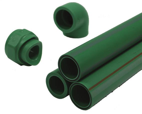
9 PP-RCT AT A GLANCE that has been tested and found to be in conformance with NSF/ANSI Standard 61 Drinking Water System Components Health Effects. When plastic pipe or fittings are NSF/ANSI Standard 14 listed, and have the NSF-pw (potable water) mark, they also meet the NSF/ ANSI Standard 61 requirements. The NSF-pw mark certifies to installers, users, and regulators that the product meets the requirements of NSF/ANSI Standard 14 for performance and the NSF/ANSI Standard 61 for health effects. Biological Resistance To date, there are no documented reports of any fungi, bacteria, or termite attacks on any plastic piping system. In fact, because of its inertness, plastic piping is the preferred material in deionized and other high purity water applications. Abrasion Resistance Certain plastic piping materials provide excellent service in handling slurries such as fly ash, bottom ash, and other abrasive solutions. The material toughness and the smooth inner bore of plastic piping make it ideal for applications where abrasion resistance is needed. Low Maintenance A properly designed and installed plastic piping system requires very little maintenance because there is no rust, pitting, or scaling to contend with. The interior and exterior piping surfaces are not subject to galvanic corrosion or electrolysis. In buried applications, the plastic piping is not generally affected by chemically aggressive soil. PP-RCT PP-RCT is an advancement in polypropylene polymers and has a wide range of benefits for commercial plumbing systems. It has a more complex crystalline structure that provides greater pressure capabilities at higher temperatures than conventional PP materials. When utilized in a piping system, these enhanced mechanical properties make it suitable for higher temperature applications such as boiler and hot water systems. They also create lighter and thinner piping while maintaining the necessary system pressure ratings. PP-RCT can also be extruded in a multilayer pipe with a Fibercore middle layer. This core reduces the impact of thermal expansion on the piping system. INTRODUCTION Features and Benefits Good resistance to chemicals Weather-resistant Excellent processing capability Asahitec Socket fusion mm (1/2-5 ) Molded butt fusion from mm (6 20 ) NSF/ANSI 61/14 certified for potable water applications ASTM F2389 Molded fittings up to 20 Provides full pressure rating over fabricated fittings Cost effective vs fabricated fittings Save space with a smaller footprint Wide range of valves Ball, butterfly, diaphragm and more Complemented with reliable actuation packages Applications Potable Water Commercial Hot Water HVAC Hot Water and Chilled Water Hydronics Buried and Above Ground Water Pipes Sports Stadiums and Arenas Commercial Buildings Residential Buildings Institutional Buildings Schools and Universities Government Buildings Hospitals Hotels and Apartments A Rev B A-3

10 A INTRODUCTION PP-RCT vs Steel Pipe Weight Steel pipe weight is approximately 3.5 times greater than PP-RCT pipe. Large and complex PP-RCT spools can be welded in the shop to minimize field welds, and still be manageable to install. Less weight equates to more economical shipping and handling costs. PP-RCT requires less labor and equipment to install, thus it is a less expensive and safer system to install. PP-RCT reduces the need for heavy duty hangers and supports. Joining Steel pipes require a welding rod and open flame or arc to create the weld. PP-RCT welds require no welding rod the welds are homogeneous. There are no heat affected zones in thermoplastic fusion. PP-RCT welds require no special post-treatment such as passivation. PP-RCT butt and socket fusion welds are as strong or stronger than the pipe. PP-RCT welds require less labor to produce a proper weld. Asahitec fusion welding training provided by authorized personnel, on site or in a classroom setting. Fusion welding generates no weld slag or noxious fumes. Flow/Rates and Head Loss The H-W flow factor for PP-RCT pipes is higher than that of steel. PP-RCT AT A GLANCE energy costs over time and reduces the life expectancy of the system. Corrosion of metallic pipes can adversely affect the taste and quality of the water and increase health concerns. Asahitec Fibercore Technology Both Climatec and Watertec pipes are manufactured with patented Fibercore technology. Fibercore (PP-F) pipes consist of three co-extruded layers that make one homogeneous pipe. The middle layer consists of mixed short fiberglass strands and PP-RCT, which is isolated by solid layers of PP-RCT on the inside and outside to create an Asahitec pipe. The middle Fibercore layer reduces the expansion and contraction by up to 75 percent. This can reduce the installation cost by minimizing expansion loops and quantity of supports required in above ground systems. While the fittings do not have Fibercore, fittings weld directly to all of Asahi s PP-RCT fittings and valves. Inner Layer Solid PP-RCT Outer Layer Solid PP-RCT Figure A-1. Fibercore Middle Layer Fiberglass/ PP-RCT matrix Corrosion PP-RCT pipes for water applications do not corrode like steel pipe can. Corroding metallic pipes can introduce particles into the water system thus adversely effecting other system components such as pumps, valves, faucets and radiators. Corrosion of metallic pipes creates higher operating A-4 Rev B
11 PP-RCT AT A GLANCE Certifications, Approvals and Standards ISO Plastic piping systems for hot and cold water installations Polypropylene (PP) ASTM F2389 Standard Specification for Pressure-rated Polypropylene Piping Systems Referenced by: IPC, IMC, UPC, and UMC ASTM F2023 Standard Test Method for Evaluating the Oxidative Resistance of Crosslinked Polyethylene (PEX) Pipe, Tubing and Systems to Hot Chlorinated Water CSA B Polypropylene (PP-R) Pipe and Fittings for Pressure Applications DIN 8077 Polypropylene (PP) Dimensions DIN 8078 Polypropylene (PP) pipes General quality requirements and testing NSF/ANSI 61 Drinking Water System Components Health Effects NSF/ANSI 14 Plastic Piping System Components and Related Material Installation Requirement Standards AMSE/ ANSI B31 Pressure Piping Code (B31.1, B31.3, B31.9) DVS 2207 Welding of Thermoplastic Materials DVS 2008 Welding Machines and Devices for Thermoplastics LEED Credit Leadership in Energy and Environmental Design (LEED) is changing the way we think about how buildings are constructed, maintained and operated. Our new PP-RCT piping systems fall in line with LEED s guidelines and are considered environmentally friendly, as well as energy efficient. An Asahitec system is one of the most environmentally friendly and cost-effective piping systems. Polypropylene is inherently not susceptible to corrosion, scaling and abrasion, which gives Asahitec a projected operating life of 100 years in some cases. With a superior internal smoothness and higher velocity limits when compared to other piping systems, PP-RCT pipes will have a greater flow. This gives you a reduction in the overall power consumption of your pumps. This savings will directly lower a building s operating cost and its environmental INTRODUCTION impact. Through these characteristics, an Asahitec piping system can be implemented in a variety of building systems while contributing to multiple LEED credits. It can contribute to the Energy and Atmosphere credit by switching to a more efficient hydronic system compared to a forced air system. Extra credits can be earned when a solar collector or geothermal systems are added. The Indoor Environmental Quality credit coupled with a hydronic system can simplify the number of sensors needed at delivery points in a forced air system, while being able to provide thermal comfort to individual occupants or multi-occupant spaces without discomforting drafts. Asahitec can contribute to the Sustainable Sites credit through rainwater collection systems and recycled water systems. Being chemically inert, Asahitec is resistant to almost all acids, alkalies and organic solvents, and being freeze tolerant it makes the perfect pipe for direct burial in an application like this. Short Specification Plumbing (hot and cold water) and HVAC piping systems shall be polypropylene pipe and fittings made of PP- RCT resin and certified by NSF International to 14-pw potable water. Material shall comply with NSF/ANSI 61 covering health effects requirements when tested at temperatures up to and including commercial hot water (180 F). Product shall be certified to the Universal Plumbing and Mechanical Codes UPC and UMC, ASTM F 2389 and 2023 or CSA B Pipe shall be extruded with Fibercore middle layer technology to limit thermal expansion. Pipe shall be identified by green color with grey stripes and/or one red stripe. Fittings shall be molded only in green color; socket fusion style in sizes 1/2 5 and butt fusion style in sizes SDR ratings may span 7.4, 9, 11 and 17 sizes, depending upon system pressure/temperature requirements. All pipe and fittings shall be Asahitec, Climatec or Watertec as corresponding to required SDR sizing, available from Asahi/America, Inc. of Lawrence, Massachusetts. A Rev B A-5
12 Page left blank intentionally A A-6 Rev B
13 Section B ENGINEERING AND DESIGN CRITERIA Contents Introduction... B-2 Material Properties Chart... B-2 SDR Design Basis... B-3 Operating Parameters... B-4 Precautionary Note... B-5 Chemical Resistance Request... B-6 Rev B B-1
14 MATERIALS ENGINEERING & DESIGN CRITERIA Introduction B This section of the guide is to assist in the engineering and theory of a thermoplastic pipe system. Asahi/America provides the theory and the data on the design within this section. When designing a pipe system, all of the topics in this section should be considered. The complexity of your system will dictate how detailed the engineering needs to be. For safety reasons, it is important to consider all topics. While thermoplastics provide many advantages in terms of weight, cleanliness, ease of joining, corrosion resistance, and long life, they do require different considerations than metal pipe and valves. Like any product on the market, thermoplastic has its advantages and its limitations. Use the engineering data in this design guide for optimal results in a thermoplastic piping system. Familiarize yourself with the following material properties of PP-RCT. Note the significant difference in Fibercore s coefficient of expansion. Property Standard Unit PP-RCT Fibercore Specific density at 23 C ISO 1183 g/cm MFR 190/5 ISO 1133 g/10min MFR 230/ Mechanical Properties MFI range ISO1872/ T003 - Tensile stress at yield ISO 527 MPa 25 - Elongation at break ISO 527 % >300 - Flexural strength (3.5% flexural stress) ISO 178 MPa 23 - Modulus of elasticity ISO 527 MPa Thermal Properties Linear coefficient of thermal expansion DIN K-1 x Thermal conductivity at 20 C DIN W/(m x K) Specific heat at 20 C - kj/kg K Specific volume resistance VDE 0303 OHM cm - - Specific surface resistance VDE 0303 OHM > Electrical Properties Relative dielectric constant at 1 MHz DIN Physiologically non-toxic EEC 90/128 - Yes - FDA - - Yes - UV stabilized - - No - Color - - RAL Table B1. PP-RCT/PP-F Material Properties Design Basis Inside Diameter and Wall Thickness The ID of a pipe can be based on various standards. The two common standards for determining the ID or wall thickness of a pipe are a schedule rating and a standard dimensional ratio (SDR). Normally, metal pipes and PVC pipes are sized according to schedule ratings. A common schedule rating for PVC is Schedule 40 or 80. The higher the number, the higher the pressure rating. In schedule systems, no matter what the material, the wall thickness will always be the same for the nominal diameter. For example, a Schedule 40 PVC pipe will have the same wall thickness as a Schedule 40 PVDF or PP pipe. The pressure ratings will be significantly different based on diameter of pipe and the material mechanical properties. Schedule ratings offer the convenience of tradition and dimensional consistency. However, it is not a practical rating system for plastic pipe with various material properties. The conclusion is that schedule ratings ignore material properties and, in many cases, waste excess material and cost just to meet the required wall thickness of the standard. B-2 Rev B

15 ENGINEERING & DESIGN CRITERIA MATERIALS A more precise system in use is the standard dimensional ratio (SDR). This is a ratio between the OD of the pipe and the wall thickness. SDR is simply the outside diameter of the pipe divided by the wall thickness. All polypropylene pipes supplied by Asahi/America are produced according to ISO 4065 standards, which outline a universal wall thickness table. The SDR system allows for the same pressure ratings for all pipes within that SDR. From the standard, the following equation for determining wall thickness is derived.. SDR = OD/s, OD = Outside diameter (mm), s = wall thickness (mm) The SDR class, operating temperature, and service life of the pipe are factors in determining the hoop stress of the pipe under a given set of conditions. Using Figure B1, we can input this value into Equation B1 to find the max operating pressure for a given temperature and expected life span. B P max = 20*σ_v (B1) (SDR-1)*C min P max = Max Operating Pressure (bar) σ v = Reference Strength (N/(mm 2 ) (also referred to as hoop stress) SDR = Standard Dimensional Ratio C min = Minimum Safety Factor Figure B1. Creep curves for expected strength of PP-RCT The reference strength is a composite graph called a creep curve. This graph is based off of experimental and mathematical formulas. Above is the creep curve (ISO : 2013) for PP-RCT. The Y axis is the hoop stress in N/mm 2. The X1 axis is the time to failure in hours. The X2 axis is the time to failure in years. Rev B B-3
16 MATERIALS ENGINEERING & DESIGN CRITERIA B. ( F) Operating Years PP-RCT (psig) Table B2. PP-RCT Operating Parameters *Safety factor of 1.25 used per inch to 99 For temperatures below 68 F (20 C) and down to 23 F (-5 C), the pressure chart for 68 F (20 C) can be used. Limiting impacts and vibrations to the pipe becomes significantly more important as the temperature and wall thickness of the pipe decrease. PP-RCT s creep curve (DIN-8078) has a low-end temperature of 50 F (10 C). However, through experience and testing we have extended uninsulated Asahitec s low temperature limit down to 23 F (-5 C). Please contact Asahi/America s engineering department for design considerations when the application is outside of the pressure/temperature chart. It is important to verify that the material is suitable for use and that the piping system will be capable of withstanding the chemicals under the concurrent pressure and temperature and other loads under which it will operate. Chemical resistance is dependent on a number of specific factors that include more than the concentration of the B-4 chemicals and the temperatures that will be handled. Other factors include, but are not limited to, the concurrent temperature, pressure, and other internal and external loads imposed on the system. The duration of application (i.e. continuous vs intermittent), steady vs cyclic loading, consideration of other chemicals that may be mixed together with the chemical under question, and the design codes to which the system is being implemented (e.g. ANSI/ASME). While these charts may serve as a general guideline for the determination of resistance, it is recommended to contact the factory for further guidance for any chemical application of Asahitec. The final determination will be the responsibility of the engineer in charge of the project or other representative of the owner. Asahitec has a high temperature resistance making it suitable for a wider range of applications. PP is generally suitable up to a maximum temperature of 203 F, while high density polyethylene (HDPE) is rated to a maximum operating temperature of 140 F. HDPE (class and resin dependent) is a ductile material, which makes it preferable for lower temperature applications. Asahi/America has a very detailed corrosion resistance database available for these specific products, which includes over 600 corrosive solutions at a variety of concentrations and operating temperatures. Asahi/ America maintains databases of all its chemical projects. Chemical verifications conducted by resin manufacturers are also kept on file for reference. When using water treatment control additives, consult Asahi/America for a written recommendation on the specific application. To receive a documented recommendation, submit the chemical concentration, temperature and operating pressure to Asahi/America engineering department. A Chemical Resistance Check Request form is included on the next page. Rev B
17 ENGINEERING & DESIGN CRITERIA MATERIALS Precautionary Note: Mixed use applications in recirculating domestic hot water systems may contain copper components that are used in hot water heaters, distribution headers, plumbing connections, and other equipment. Careful design is important and proper installation in accordance to the Copper Development Association - CDA Publication A /16 The Copper Tube Handbook, will eliminate conditions that could cause copper erosion and corrosion, which can have negative effects on thermoplastic piping systems. Further information can be found in the Plastic Pipe Institute s Technical Note- TN57; PPI TN-57/2018: Proper Integration of Copper Tubing and Components with PP-R Piping Materials for Plumbing Applications Note: Hydronic and other hot water heating systems are typically not affected by copper erosion due to the lower flow velocities, lower dissolved oxygen, and oxidant levels. The presence of oxidants and oxygen in extreme hot water is typically found only in domestic (potable) water applications. B Rev B B-5
18 MATERIALS ENGINEERING & DESIGN CRITERIA CHEMICAL RESISTANCE CHECK REQUEST FORM PIPING SYSTEMS Attention: Engineered Products Division Requester s Information B Company Name: Address: Phone: Fax: Contact Name: Project Information End User Name: Project Name: Contact: Address: Phone: Chemical Information Chemical(s) and Concentration: Operating erature: Operating Pressure: Flow Rates: UV Exposure: Comments: (Please note any other information that may assist in material selection) Figure B2. Chemical Resistance Check Request Form B-6 Rev B
19 Section C SYSTEM OPERATING CHARACTERISTICS Contents Fluid Dynamics... C-2 C-1
20 C FLUID DYNAMICS Fluid Dynamics Sizing a thermoplastic piping system is not much different than a metal piping system. Systems transporting compressible fluids and non-compressible fluids are sized very differently and have different concerns. Asahitec piping is specifically designed for hot and cold water applications, so only non-compressible fluid flow will be summarized. Pipe diameter is a critical factor in properly designing the Asahitec pipe system. It is generally recommended that the flow velocity in Asahitec piping systems not exceed 8 fps for clean water. This promotes efficient pumping, control of noise generation, and dampens the effects of water hammer on the piping system. Pump suction piping velocity is usually recommended to be less than 5 fps. Higher velocities are also possible, contact Asahi/America engineering for assistance. Once pipe sizes have been determined for the system, the following equations can be used to determine the system pressure drop and to select pump motor horsepower. When determining frictional pressure loss across a system, it is recommended that a 20percent safety factor be used to account for fitting pressure drop elimination, non-smooth welds and manufacturing tolerances. Darcy Method h f = Friction loss from flow in the pipe/fittings (ft) L = Length of pipe and/or equivalent length of pipe fitting (ft) D = Inside diameter of pipe (ft) V = Average flow velocity within pipe (ft/s) g = , gravitational constant (ft/s 2 ) f = Friction factor The Darcy-Weisbach equation can be used to determine the friction loss for Asahitec piping systems. It can be used to determine the system's friction loss across pipe, fittings, and valves. All the variables in the Darcy equation can be easily acquired, but for the friction factor one must first calculate the Reynolds number. The Reynolds number is dimensionless and is used to determine if the flow is laminar or turbulent. RE = (Vd/v) Re = Reynold number d i = Inside diameter of pipe (inch) V = velocity (ft/s) g = (ft/s 2 ) v = kinematic viscosity (centistokes) The Reynolds number allows the friction factor to be determined. Depending on how large or small the Reynolds number will determine which equation should be used to calculate the friction factor. For Reynolds numbers <2000, the flow condition is considered to be a laminar flow condition. For a laminar flow condition use the following equation to calculate the friction factor. For Reynolds numbers >4000, the flow condition is considered to be a turbulent flow condition. For turbulent flow conditions the Colebrook equation is used to calculate the friction factor. Colebrook Equation FLOW VELOCITY A Moody Diagram can be used to determine the friction factor as well. It can be used to determine the friction factor in laminar flow conditions, transitional flow conditions, or turbulent flow conditions. To use the Moody Diagram, first calculate the Reynolds number and a relative roughness number. Use these numbers with a Moody Diagram to determine the friction factor. An equation for relative roughness is shown below. є = E-05, Absolute roughness of polypropylene pipe (ft) C-2
21 FRICTION LOSS FLUID DYNAMICS Friction Head Loss Across Pipe Measure the developed length of pipe (the length of pipe in the system containing the same pipe diameter and same average flow velocity). Insert this length along with the average flow velocity and pipe diameter into the Darcy- Weisbach equation to calculate the frictional head loss of the pipe. Where L= L (developed length). =SG Hv= Friction Head Loss Across a Fitting Head loss in fittings is frequently expressed as the equivalent length of pipe that is added to the straight run of pipe. This approach has sufficient accuracy for many applications. A table for equivalent length of pipe is in the Appendix (Figure AP-24). Select the fitting's equivalent pipe length from the fitting table and use this length in the Darcy-Weisbach equation to determine the frictional head loss across the fitting. Where Le=L (fitting equivalent length). hv = head loss through valves (ft) P is in psi and Q is in GPM Hazen-Williams Method The Hazen-Williams equation is applicable to water pipes under conditions of full turbulent flow. It provides a sound conservative design basis for plastic pipe sizing. The variables for the equation are: D = Inside diameter of pipe (inch) Q = Volumetric pipe flow (gpm) C = Flow coefficient Hf = Friction head (ft of water/100 ft of pipe) C If the pipe and fitting have identical sizes and flow, the equivalent length of the fitting and the developed length of the pipe can be summed together as a combined equivalent length, which can be used to determine the frictional head loss across the combined length of pipe. Where L= L (developed length) + L (fitting equivalent length). ht=hp+hf C = 150 for polypropylene pipe C = 100 for carbon steel (standard design factor) To determine the pressure loss in psi/100 ft of pipe = Asahi/America has already calculated the pressure drop in our pipe systems at most flow rates using the Hazen-Williams method. These tables are in the appendix starting at Table AP-3. Frictional Head Loss Across a Valve The flow coefficient or Cv of a valve is defined as the number of gallons of water at 60 F that flows through the valve creating a pressure drop of 1 psi across the valve. To determine the pressure drop across the valve, insert the density of the chemical flowing through the valve, the volumetric flow rate, and the manufacturer's flow coefficient. SG = specific gravity (density of the fluid/density of water at 68ºF. C-3
22 Page left blank intentionally C C-4
23 Section D PIPE SUPPORT AND THERMAL EXPANSION Contents Support Spacing....D-2 Pipe Supports...D-3 Thermal Expansion & Contraction... D-5 Expansion Charts & Calculator.... D-6 D-1
24 SUPPORT Support Spanning for Asahitec Pipe Types SUPPORT SPACING The permissible support distances of thermoplastic pipes are determined by the SDR of the pipe and the operating temperature of the media. A thicker walled pipe and a lower temperature system will both contribute to a longer support spacing distance, while thin walled pipes and high operating temperatures will result in shorter hanger spacing. Below are the maximum hanger spacing distances for Asahitec pipe. This includes loose point (LP) guides and locating point or fixed point (FP) supports. Thermal growth needs to be evaluated to determine LP and FP supports location. See details in this section below. Note that the hanger distances will differ if the pipe has Fibercore. D If the system is exposed to thermal cycling the placement of hangers, guides (LP), and anchors (FP) is critical. In these cases, the hanger locations should be identified by the system engineer and laid out to allow for expansion and contraction of the pipe over its life of operation. Support spacing for SDR-7.4 Solid Wall (inches) Support Spacing for Fibercore Table (inches) Support spacing for SDR-11 Solid Wall (inches) D-2 Size 68 F 86 F 104 F 122 F 140 F 158 F 176 F 1/ / / / / Table D1. PP-RCT Support Spacing Size 68 F 86 F 104 F 122 F 140 F 1/ / / / / Table D2. PP-RCT Support Spacing Size SDR 68 F 86 F 104 F 122 F 140 F 158 F 176 F 1/2" /4" " /4" 1-1/2" 2" 2-1/2" 3" 4" 5" 6" 8" 10" 12" 14" 16" 18" 20" Table D3. Support Spacing for Fibercore Pipe

25 PIPE SUPPORTS SUPPORT Pipe Support Types for Asahitec When selecting hangers for a system, it is important to avoid using a hanger that will place a pinpoint load on the pipe when tightened. For example, a U-bolt hanger is not recommended for thermoplastic piping. If metal clamps are specified for the project, they should be inspected for rough edges that could damage the pipe. Ideally, if a metal clamp is being used, an elastomeric material should be used in between the pipe and the clamp. Figure D-2. Recommended clamp If a clamp will be used as an anchor and it will be exposed to high end loads, a more heavy duty clamp may be required, as well as a special anchoring setup. In these cases, it is advised to either consult a mechanical engineer with experience in pipe stress analysis or receive detailed recommendations from the clamp manufacturer. D Figure D-1. NOT RECOMMENDED U-bolt on PP-RCT Hangers that secure the pipe 360 degrees around the pipe are preferred. It is recommended to use plastic pipe clips that hold the circumference of the pipe and prevent pinpoint stress. Pipe clips should be used as secure supports and guides only. Do not tighten down hard on the wall of the pipe as the pipe must be able to move through the support. Continuous support may also be used. Metal clamps that contact the pipe are not recommended. To handle expansion and contraction, a restrained system that limits the movement of the pipe is preferred over the use of loops and offsets. Restraint fittings should be used to protect fittings from excessive movement and to reduce the amount of movement between restraints. D-3
26 SUPPORT PIPE SUPPORTS D Figure D-3. Typical plastic piping supports D-4

27 EXPANSION AND CONTRACTION Thermal Expansion and Contraction Based on operating criteria, thermal expansion must be considered. For systems maintained at consistent temperatures, compensation for thermal effects may not be required. It is, however, important to review all aspects such as the operating environment. Is it outdoors where it will be exposed to changing weather? Is the system spiked with a high temperature cleaning solution? Will the system run at a significantly higher temperature than the installation temperature? The occurrence of any thermal change in a plastic system will cause the material to expand or contract. As an example of the effect, Asahitec solid wall will grow roughly one inch for every 100 linear feet and 10 degrees F ΔT, while Fibercore will grow less than a 1/4 under the same conditions. Thermoplastic systems can be used in hot applications and applications where the temperature is cyclical, but they require analysis of the thermal expansion effects. In most cases, the use of expansion loops, offsets and proper hanging techniques are all that is required to ensure a proper design. SUPPORT For expansion calculation tools, please visit our website at: Below is an example from the online calculator. D Hot media also reduces the rigidity of thermoplastic piping, which, in turn, decreases the support spacing between pipe hangers. In smaller dimensions, it is recommended to use continuous support made of some type of channel or split plastic pipe. Finally, the use of hangers as guides and anchors becomes important. As the design proceeds, certain hangers should be used as guides to allow the pipe to move back and forth in line, while other anchoring locations should be used to direct the expansion into the compensating device. The anchors and hangers should be designed to withstand the end load generated by the thermal expansion. Figure D-4 is an example of an anchor type restraint fitting that is available from Asahi/America. The change in length that the pipe will experience dictates how long the bending arms are and where to anchor them. Figure D-5. Expansion Calculator Example Figure D-4. Restraint fitting D-5
28 SUPPORT EXPANSION D Figure D-6. Alternate Support for Thermal Growth Burial Practices for Asahitec Piping Similar to pipe clips and supports, when burying Asahitec, it should be protected from point loads like rocks in the ground. The most common solution is to dig an extra wide trench and backfill it with sand to protect the pipe against any point loads. If an application requires Asahitec piping to be buried, please contact Asahi/ America for recommend burial practices. If Asahitec piping is being buried for freeze protection or other design requirements, please contact Asahi/America. Figure D-7. Typical Plastic Pipe Preparation D-6
29 Section E THERMODYNAMIC FACTORS Contents and Loss...E-2 R-Values....E-2 Insulation....E-3 Thermal Conductivity....E-3 E-1
30 THERMODYNAMIC FACTORS HEAT GAIN/LOSS HEAT GAIN & HEAT LOSS Thermal insulation is installed on most piping systems that operate outside of ambient conditions. It not only saves energy and money for the owner, but it protects workers, attenuates noise, and protects against freezing. The following calculations will provide you with information on how to determine the most cost effective solution when deciding on how to insulate a piping system. Conduction happens through both the pipe and the insulation, and since they have different thermal conductivities, they need to be calculated separately. The conduction of the fluid and the pipe is denoted by = inside film coefficient (BTU/hr-ft 2 -F), while the convection on the outside surface is = outside convective film coefficient (BTU/hr-ft 2 -F). E Piping insulation s main use is to limit heat loss from the fluid in a hot system, or limit the heat gain of the fluid in a chilled system. flows in the direction of the temperature gradient and does so by conduction, convection or radiation. The equation below is for conductive heat transfer through a flat slab. q = heat loss or heat gain (BTU/hr) k = thermal conductivity (BTU-in/hr-ft 2 -F) A = area (ft 2 ) x = thickness (inches) This simple equation when applied to pipes, changes slightly due to the thickness not being flat. In this case the cylindrical geometry is mathematically shown by the equivalent thickness, as shown in the denominator of the below equation. R-Values Bare Asahitec pipe material is considered to have excellent insulation characteristics with its low thermal conductivity value. Competing metal pipe such as copper, steel, and stainless steel are all considered poor insulators. Comparing the heat loss/gain charts of bare Asahitec pipe to the heat loss/gain chart of metal pipe it is easy to see the thermal advantages which Asahitec pipe provides. With a 50 F temperature difference across the pipe, the heat loss/gain of the metal pipe is much greater than that of Asahitec. There are two terms used to describe the heat loss within a pipe, K-Factor and R-Value. The K-Factor is also known as thermal conductivity. The thermal conductivity of a material is based on the number of BTUs per hour that pass through a one-inch-thick by one-square-foot section of material, with a 1 F temperature difference between the two surfaces. The lower the K-Factor, the more suitable the material is for insulation. r 1 = radius of inner surface (in.) r 2 = radius of outer surface (in.) K-Factor Material (BTU/hr-ft- F) Pipe Insulation PP-RCT Steel 31 Copper 227 Table E1. PP-RCT K-Factor E-2
31 INSULATION THERMODYNAMIC FACTORS R-Value is a measure of the ability of a material to retard heat flow rather than transmit heat. The higher the R-Value, the better the insulator. For cylindrical pipe geometry equivalent thickness, use the equation shown below to determine the equivalent thickness since the outer surface area of insulation is proportionately greater than the inner surface area. The equivalent thickness is the insulation thickness of a flat surface which would equal the heat flux at the outer surface, of a cylindrical geometry. The relationship between R-Value and K-Factor for pipe insulation is in the equation shown below. Table E-2 displays the R-Values for Asahitec pipe at 68 F. Insulation There is a definite thermal efficiency advantage associated with using Asahitec pipe to that of using metallic. The charts in the appendix display both the heat gain and loss in different conditions, as well as with or without insulation. When calculating the thermal gain/ loss, the radiation and inner pipe heat film resistance is usually not included. Keep in mind that local codes will usually dictate the insulation thickness depending on the type of system and operating temperature of the system. E Calculated/Determined Values R Pipe = Thermal resistance of pipe wall (hr ft F/BTU) To convert BTU/hr-ft-F to BTU-inch/hr-ft 2- F multiply by 12 in/ft Size SDR 7.4 SDR 9 SDR 11 SDR 17 1/2" (20mm) /4" (25mm) " (32mm) /4" (40mm) /2" (50mm) " (63mm) /2" (75mm) " (90mm) " (110mm) " (125mm) " (160mm) " (200mm) " (250mm) " (315mm) " (355mm) " (400mm) " (450mm) " (500mm) R Ins = Thermal resistance of pipe insulation (hr ft F/BTU) R O = Thermal resistance of outer air (hr F/BTU) R Total = Total thermal resistance of pipe and pipe insulation (hr ft F/BTU) Table E2. PP-RCT R-Values E-3
32 Page left blank intentionally E E-4
33 Section F INSTALLATION Contents Socket Welding.... F-2 Butt Welding... F-6 Saddle Welding.... F-7 Electrofusion Welding.... F-7 Testing...F-9 F-1

34 F INSTALLATION The following information is a reference guide for welding and installation methods. Please refer to the appropriate DVS standards and welding tool O&M manuals for complete instructions. Transportation and Storage Prevent impacts to the pipe ends. Prevent excessive loads. Prevent improper stacking. A solid flat and level base for the pipes must be provided in order to avoid deformation of the pipes while in transport or storage. If the pipes are stacked to excessive heights, it can lead to ovalization or bowing of the pipes. Asahitec pipes may be stored outside at any temperature if protected from UV light. It is preferable to store pipes inside whenever possible. The pipes are shipped in black protective polyethylene bags. However, the protective bags may become ripped or torn during shipping and sections of the pipe may become exposed. When storing outside, the pipes should be inspected to ensure that they are thoroughly covered and protected from the effects of UV light. Maximum outdoor storage time is 30 days if removed from the factory-supplied UVprotective bags, or for portions of pipe that are exposed due to rips or tears in the bags. Outdoor Installation UV radiation has an effect on polymeric plastic products. Protect pipes against weathering and UV radiation to prevent damage. In applications where the installed pipe will be exposed to UV radiation (such as rooftop or other outdoor applications), it is recommended that standard Asahitec piping be provided with UV protection. The piping can be protected by a number of methods including priming with plastic primer spray and painting. The piping can also be protected by use of protective tapes or covered with insulation or insulation jacketing. At temperatures below 32 F (0 C), the piping has less ductility and it is more susceptible to damage by impact (especially against pipe ends), excessive loads, crushing or bending. Handle pipes with care at low temperatures. Socket Welding Overview SOCKET WELDING The Asahitec system is joined by socket fusion. Use Type A heater bushings in conjunction with a suitable hand-held heater plate or socket fusion bench tool. After the correct welding temperature has been reached, the joining can proceed. The pipe and fitting faucet diameters, as well as the respective heated bush diameters, are matched to build up the necessary pressure during the joining process. Asahitec pipe does not need to be scraped before socket welding. The pipe may be beveled for easier insertion, especially on larger diameters. Push the pipe and fitting quickly and axially up to the stop of the mandrel and the marked insertion depth respectively and keep them fast without twisting. The heating of the joint faces is done according to the table in Table F2 (page F-4). At the end of the heating period pull the pipe and the fitting from the heating element of the suitable polywelder and join them immediately axially aligned and without twisting. Mind the correct insertion depth (Table F1, page F-3). Do not expose the welded joint to mechanical stress before the expiration of the cooling period (see Table 2, page F-4). Figure F-1. Measure and cut pipe with suitable pipe cutters to the correct length. Pipe must be squared 90 degrees. F-2


35 SOCKET WELDING Size Pipe Depth (In.) 20 1/ / / / / Table F1. PP-RCT Insertion Depth INSTALLATION Figure F-4. Join fitting and pipe in the axial direction. During joining do not twist the pipe or fitting. Figures F-A, F-B, and F-C show the three welding process stages. A - Welding preparation B - soak C - Welded joint F Figure F-A. Figure F-2. Mark the weld insertion depth on the pipe. Figure F-B. Figure F-3. Push the pipe end and the fitting onto the heating element of the hand socket welder in the axial direction. pipe and fitting simultaneously. The pipe and the fitting are to be removed from the hand socket welder. Figure F-C. F-3
 4 2 6 4 8 6 10 8 1. Fusion temperature is 500 ± 15 F (260 ± 10 C) 2.")
 please contact Asahi/ America for new values.")

36 F INSTALLATION Size Pipe Soak Time (Sec) 20 1/ / / / / Changeover (Sec) Table F2. Standard values for socket fusion Notes: Cooling (Min) Fusion temperature is 500 ± 15 F (260 ± 10 C) 2. Use Asahitec depth gauge for marking correct insertion depth. 3. These values are for room temperature of 68 F (20 C). If room temperature is <41 F (5 C) please contact Asahi/ America for new values. SOCKET WELDING Pipes are measured and cut with suitable pipe cutters to the required length. Cutting should be perpendicular to the pipe axis. Figure F-6. Place and adjust the fitting in the clamping jaw and adjust the stop to hold the fitting. Figure F-7. Lay the pipe axially to the fitting and position it so that it is situated flush to the fitting. Figure F-5. Benchtop Socket Welding Machine Set the heating element in the holder. Mount the suitable welding tools (bushing and mandrel) and install the clamping jaws. F-4


37 SOCKET WELDING INSTALLATION Welding: Switch on the socket welding machine. The temperature control lamp goes off after reaching the operating temperature (500 F). erature tolerance ± 15 F. The first welding should take place within five minutes after the welding temperature has been reached. Split apart the machine slides and close down the heating element. Slowly move the machine slides by turning the hand wheel. Align the heating element so that the pipe and the fitting fit properly into the welding tools. Clean pipe and fitting with 99% isopropyl alcohol. Move the slides with steady forward motion until the stop has been reached. The heating timer of the joint surfaces starts only after the stop has been reached. After completion of the heating time the slides will be split and the heating unit must be brought into a rest position as fast as possible. Move the machine slides with the hand wheel with a steady forward motion up to the stroke end so that the precise jointing depth between the pipe and the fitting is reached. The welded joint may be removed from the clamping jaws only after cooling down. Unscrew the clamping jaw with the handle lock and take off the welded unit. Figure F-10. Move the machine slides with the handle lock and remove the heating element. After the warming time, weld the pipe and the fitting. F Figure F-8. Move the machine slides with the handle lock to set the heating element into the center between pipe and fitting. Figure F-11. Move the machine slides up to the stoke end. Figure F-9. Move the machine slides with the handle lock, warm up the pipe and the fitting in the welding tools. F-5

. Figure F-13.")


38 INSTALLATION BUTT WELDING Butt Welding Figure F-12. Trench Butt Welding Machine Preparation Cut the pipes with a suitable sawing machine to the required length. F Figure F-14. During butt welding with heating elements, the areas to be joined are heated up to the welding temperature and brought together by prescribed pressure after the heat element has been removed. ing temperature 410 F (±18 F). Figure F-13. The spigots of the fittings have to be planed with a planing tool. Ensure that the spigots of the fittings are always planed before every weld. Welding Procedure: During butt welding, the areas to be joined are pushed into the heating element at a specified force until the specified bead height is reached. Continue heating up to the welding temperature with reduced pressure (14.5 ±1.5psi) for a prescribed time then, after removing the heating element, join the pieces with merging pressure. Please see welding tool O&M manual for specific welding parameters. Figure F-15. Check to see that a uniform double bead has been formed and rolled over; this indicates a successful welding. F-6
.")


. Figure F-17.")
39 SADDLE WELDING Saddle Welding INSTALLATION Additional extension of existing pipe systems: Direct connection of existing pipe to a utility line. Alternative to T-pieces. Welding Preparations: up the heating unit to 500 F. Check the preset temperature prior to the welding process. erature tolerance (±15 F). The welding elements must be clean and should be cleaned prior to every welding process. Figure F-18. Push the connecting piece of the welding saddle quickly into the heated bore hole. Push the fitting for about 15 seconds onto the pipe. After a cooling time of about 10 minutes the fused joint can be operated under pressure. The appropriate branch connections will be assembled through socket fusion welding or by using female or male adapters with the welding saddle. Electrofusion Welding F Figure F-16. To drill through the pipe wall, an electric drill and correctly sized drill big, supplied by Asahi/America, are required. Figure F-19. Cut the PP-RCT pipe ends rectangularly to the pipe axis with a suitable pipe cutter. Remove in chips the outer surface oxide layer with a suitable scraper and purify with non-fuzzing, absorbent paper and purifying agent (e.g. alcohol). Figure F-17. Insert the male tool bushing into the drilled hole while pushing the fitting spigot into the female tool bushing. The heating time for all dimensions is about 30 seconds. Both pieces of pipe must be supported and restrained against movement or external forces. If the pipe is out of round (especially important on larger sizes), a suitable rounding tool will need to be used. F-7
, we recommend using a peeling tool similar to the one shown above for removing the outside oxide layer. Clean the joint surfaces with a purifying agent (e.g. alcohol) and mark the bushing depth.")


40 INSTALLATION ELECTROFUSION F Figure F-17. Remove the outside oxide layer using a scraper. For dimensions larger than 3 (90mm), we recommend using a peeling tool similar to the one shown above for removing the outside oxide layer. Clean the joint surfaces with a purifying agent (e.g. alcohol) and mark the bushing depth. Mounting of the Electrofusion Welding Sockets. Mark the socket depth on the pipe. After finishing all preparatory work, take the electrofusion socket out of its packaging - do not touch the inner surfaces of the socket - then push the socket slowly onto the pipe to the marked position. Figure F-19. Align the pipes and the electrofusion socket by using an aligning tool. Figure F-20. Plug the cables in to the terminals of the electrofusion coupling. Connecting the Socket Cord Figure F-18. Push in the electrofusion socket up to the marked position on the pipe. F-8 Repair Work with the Electrofusion Welding Socket. Remove the defective pipe by cutting a rectangular section of at least three to four times the socket length to its axis. Fit the new pipe piece into the gap and prepare the ends of the old pipe and new pipe piece as previously described. Unpack two electrofusion sockets and push them completely over the two ends of the new pipe piece. Now fit in the new pipe piece and move the sockets to the marks on the old pipe. Position the electrofusion welding sockets in a way offering the easiest connection of the cord plugs to the contact leads. Having checked that the required generator voltage is available, switch on the device and plug the cords into the terminals. The electrofusion machine automatically calculates and controls the required welding time and shows the welding indicators after completion. The welding indicator does not indicate the weld quality. Its value may differ depending on the slot width between the electrofusion welding socket and the pipe.


41 TESTING INSTALLATION All parameters of electrofusion are contained in the bar code and show welding time, working voltage and cooling time. Figure F-21. The welding data can be seen on the bar code label of the socket. The data can also be read by the bar code scanner of the electrofusion machine. F Figure F-22. Start the welding device from the switch. Cooling Time Observe the required cooling time. F-9
42 F INSTALLATION Pressure Testing STATEMENT OF USE The following information is intended to provide a general overview of pressure testing requirements for Asahitec PP-RCT piping systems. A pressure test must be performed, documented and submitted to Asahi/America, Inc. in order to receive the available extended warranty. The customer, contractor and design firm should agree upon pressure test criteria applicable to their pipeline and follow all local codes or governing agencies. SAFETY Pneumatic or gas pressure tests are not recommended above 5psi Pressure tests should be conducted between 50 F and 90 F Before pressure testing, all welded joints must be completely cooled down (one hour after the last welding process) If leaks are found in welds during the pressure test, the system should be depressurized and drained prior to fixing APPARATUS & EQUIPMENT Equipment used to isolate sections shall be rated equal or higher than test pressure to be applied Air release devices should be located at every high point Follow local jurisdictions for supply and disposal of the water test media Pressure regulators and gauges must be utilized in order to ensure accuracy and safety Pressure gauges should have accuracy better than 1% of full scale PROCEDURE SETUP It may be necessary to flush the system to remove any debris from installation PRELIMINARY STATIC TEST (required) 30 minutes TESTING Fill the system with water at a rate that does not exceed the capacity of the high point vents to release air Apply incremental pressure to achieve test requirement of 1.5 times the operating pressure or 150psi, whichever is higher, using a centrifugal pump. Do not exceed the lowest pressure rated component in the system or remove the low pressure rated items during system pressure test Apply pressure at the following guide rates: Up through 5 (125mm) at 3% per minute (150psi test pressure = 4.5psi/min) 6 (160mm) through 14 (355mm) at 1% per minute (150psi test pressure = 1.5psi/min) 16 (400mm) and larger at 0.5% per minute (150psi test pressure = 0.75psi/min) The pipe system will expand during initial pressurization, which will result in pressure loss. If pressure loss is less than 10psi, continue to next test If pressure drops more than 10psi in 30 minutes, stop and repeat the primary static test Continued failure indicates leaks exist. Locate the leak and repair the system PRIMARY STATIC TEST (required) 120 minutes Repressurize the system to the test pressure and monitor for 120 minutes Pressure loss of more than 5psi is considered a failure PRIMARY CYCLICAL TEST (required) Release the system pressure to 0psi Repressurize to test pressure and hold for two minutes. No pressure drop is allowed Reduce pressure to 15psi and hold for two minutes. No pressure drop is allowed If no pressure drop is witnessed, release the pressure to 0psi and repeat three more times with final intervals of five minutes If more than 0.5psi pressure drop occurs, restart from the primary static test INITIAL TEST <5psi Air Test (recommended) five minutes Conducting an initial test with compressed air will identify any joints that are not fully fused or threads that are not fully tightened prior to introducing water to the system Ability to retain 5psi for five minutes will indicate that no connections remain loose and to continue F-10 with the fluid test

43 TESTING Process Flow Diagram INSTALLATION F Figure F-23. Process Flow Diagram F-11
44 INSTALLATION Example: System Pressure During Test TESTING F Figure F-24. System Pressure Test F-12 Figure F-25. System Pressure Test
45 APPENDIX Section C CHARTS Contents Dimensions and Flow Rate Charts SDR AP-2 SDR 9... AP-5 SDR AP-8 SDR AP-12 Equivalent Loss Fitting Chart... AP-15 Loss Charts... AP-16 Charts... AP-17 Specifications... AP-27 Standards and Listings... AP-31 Soil Load Chart... AP-32 AP-1
46 APPENDIX PRESSURE RATING SDR 7.4 Nominal Diameter d s d1 Weight (in) (in) (in) (lb/ft) 1/2" /4" " /4" /2" " /2" " " " SDR 7.4 Table AP-1. Dimensions 1/2" - 5" SDR 7.4 AP Limiting impacts and vibrations to the pipe becomes significantly more important as the temperature and wall thickness of the pipe decrease. PP-RCT s creep curve (DIN 8078) has a low-end temperature of 10 C (50 F). However, through experience and testing we have extended uninsulated Asahitec s low temperature limit down to -5 C (23 F). Please contact Asahi/America s engineering department for design considerations when the application is outside of the pressure/temperature chart. AP-2
47 PRESSURE RATING APPENDIX SDR 7.4 1/2" 3/4" 1" 1-1/4" 1-1/2" Flow 20 mm 25 mm 32 mm 40 mm 50 mm Rate (gpm) V P V P V P V P V P V=Velocity (ft/s 2 ) P=Pressure Loss (ft of head/100ft) Table AP-2. Flow Rate 1/2" - 1-1/2" SDR 7.4 AP AP-3
48 APPENDIX PRESSURE RATING AP SDR 7.4 2" 2-1/2" 3" 4" 5" Flow Rate (gpm) 63 mm 75 mm 90 mm 110 mm 125 mm V P V P V P V P V P AP-4 V=Velocity (ft/s 2 ) P=Pressure Loss (ft of head/100ft) Table AP-3. Flow Rate 2" - 5" SDR 7.4
49 PRESSURE RATING SDR 9 APPENDIX SDR 9 Nominal Diameter d s d1 Weight (in) (in) (in) (lb/ft) 1/2" /4" " /4" /2" " /2" " " " Table AP-4. Dimensions 1/2" - 5" SDR 9 Limiting impacts and vibrations to the pipe becomes significantly more important as the temperature and wall thickness of the pipe decrease. PP-RCT s creep curve (DIN 8078) has a low-end temperature of 10 C (50 F). However, through experience and testing we have extended uninsulated Asahitec s low temperature limit down to -5 C (23 F). Please contact Asahi/America s engineering department for design considerations when the application is outside of the pressure/temperature chart. AP AP-5
50 APPENDIX PRESSURE RATING AP AP-6 SDR 9 1/2" 3/4" 1" 1-1/4" 1-1/2" Flow Rate 20 mm 25 mm 32 mm 40 mm 50 mm (gpm) V P V P V P V P V P V=Velocity (ft/s 2 ) P=Pressure Loss (ft of head/100ft) Table AP-5. Flow Rate 1/2" - 1-1/2" SDR 9
51 PRESSURE RATING APPENDIX SDR 9 2" 2-1/2" 3" 4" 5" Flow Rate 63 mm 75 mm 90 mm 110 mm 125 mm (gpm) V P V P V P V P V P V=Velocity (ft/s 2 ) P=Pressure Loss (ft of head/100ft) Table AP-6. Flow Rate 2"- 5" SDR 9 AP AP-7
52 APPENDIX PRESSURE RATING SDR 11 AP SDR 11 Nominal d s d1 Weight Diameter (in) (in) (in) (lb/ft) 1" /4" /2" " /2" " " " " " " " " " " " Table AP-7. Dimensions 1" - 20" SDR 11 Limiting impacts and vibrations to the pipe becomes significantly more important as the temperature and wall thickness of the pipe decrease. PP-RCT s creep curve (DIN 8078) has a low-end temperature of 10 C (50 F). However, through experience and testing we have extended uninsulated Asahitec s low temperature limit down to -5 C (23 F). Please contact Asahi/America s engineering department for design considerations when the application is outside of the pressure/temperature chart. AP-8
53 PRESSURE RATING APPENDIX SDR 11 1" 1-1/4" 1-1/2" 2" 2-1/2" Flow Rate 32 mm 40 mm 50 mm 63 mm 75 mm (gpm) V P V P V P V P V P V=Velocity (ft/s 2 ) P=Pressure Loss (ft of head/100ft) Table AP-8. Flow Rate 1" - 2-1/2" SDR 11 AP AP-9
54 APPENDIX PRESSURE RATING AP SDR 11 3" 4" 5" 6" 8" Flow Rate 90 mm 110 mm 125 mm 160 mm 200 mm (gpm) V P V P V P V P V P V=Velocity (ft/s 2 ) P=Pressure Loss (ft of head/100ft) Table AP-9. Flow Rate 3"- 8" SDR 11 AP-10
55 PRESSURE RATING APPENDIX SDR 11 10" 12" 14" 16" 18" Flow Rate 250 mm 315 mm 355 mm 400 mm 450 mm (gpm) V P V P V P V P V P ** PLEASE CONSULT FACTORY FOR 20" AND 24" DATA V=Velocity (ft/s 2 ) P=Pressure Loss (ft of head/100ft) Table AP-10. Flow Rate 10" - 18" SDR 11 AP-11 AP

 has a low-end temperature of 10 C (50 F). However, through experience and testing we have extended uninsulated Asahitec s low temperature limit down to -5 C (23 F).")
56 APPENDIX PRESSURE RATING SDR 17 SDR 17 Nominal Diameter d s d1 Weight (in) (in) (in) (lb/ft) 6" " " " " " " " AP Table AP-11. Dimensions 6" - 20" SDR 17 Limiting impacts and vibrations to the pipe becomes significantly more important as the temperature and wall thickness of the pipe decrease. PP-RCT s creep curve (DIN 8078) has a low-end temperature of 10 C (50 F). However, through experience and testing we have extended uninsulated Asahitec s low temperature limit down to -5 C (23 F). Please contact Asahi/America s engineering department for design considerations when the application is outside of the pressure/temperature chart. AP-12
57 PRESSURE RATING APPENDIX SDR 17 6" 8" 10" 12" 14" Flow Rate 160 mm 200 mm 250 mm 315 mm 355 mm (gpm) V P V P V P V P V P V=Velocity (ft/s 2 ) P=Pressure Loss (ft of head/100ft) Table AP-12. Flow Rate 6" - 14" SDR 17 AP-13 AP
58 APPENDIX PRESSURE RATING AP SDR 17 16" 18" 20" Flow Rate 400 mm 450 mm 500 mm (gpm) V P V P V P ** PLEASE CONSULT FACTORY FOR 20" AND 24" DATA V=Velocity (ft/s 2 ) P=Pressure Loss (ft of head/100ft) AP-14 Table AP-12. Flow Rate 16" - 20" SDR 17
59 EQUIVALENT LOSS APPENDIX Equivalent Loss in Fitting Chart Table AP-14. Equivalent Lengths for Asahitec Fittings (friction loss in equivalent length of pipe) Size Nominal 90 Elbow 45 Elbow Tee Concentric Reduction=D 2 /D 1 * Concentric Reduction=D 1 /D 2 ** 1/4 1/2 3/4 1/4 1/2 3/4 1/2" /4" " /4" /2" " /2" " " " " " " " " " " " *D2 = larger diameter portion, which is shown in size column **D1 = smaller diameter portion, which is shown in size column AP AP-15
60 APPENDIX HEAT GAIN Table AP-14. Asahitec PP-RCT Pipe Loss in Watts per Linear Foot AP n.i.t Nominal Diameter of Pipe in Inches ΔT n.i.t. = nominal insulation thickness of foamed elastomer in inches; ΔT = temperature difference between cold fluid and desired maintenance in F; body of table is in watts per linear foot of pipe. Values are for moving air at 20 mph velocity, assuming no outer cladding. AP-16
61 HEAT GAIN Table AP-15. Values for Asahitec PP-RCT in Still Air Conditions Nominal Insulation Thickness (inches) Fluid (F) Fluid = temperature of the chilled water (F). Pipe Size = 0.5", O.D. = 0.79" Pipe Size = 0.75", O.D. = 0.98" Pipe Size = 1", O.D. = 1.26" Ambient erature (F) Ambient erature (F) Ambient erature (F) APPENDIX AP-17
62 Table AP-15. Values for Asahitec PP-RCT in Still Air Conditions (Continued) Nominal Insulation Thickness (inches) Fluid (F) Pipe Size = 1.25", O.D. = 1.58" Pipe Size = 1.50", O.D. = 1.97" Pipe Size = 2", O.D. = 2.48" Ambient erature (F) Ambient erature (F) Ambient erature (F) so Fluid = temperature of the chilled water (F). AP-18 APPENDIX HEAT GAIN
63 HEAT GAIN Table AP-15. Values for Asahitec PP-RCT in Still Air Conditions Nominal Insulation Thickness (inches) Fluid (F) APPENDIX Pipe Size = 3.0", O.D. = 3.54" Pipe Size = 4.0", O.D. = 4.33" Pipe Size = 6.0", O.D. = 6.29" Ambient erature (F) Ambient erature (F) Ambient erature (F) so I Fluid = temperature of the chilled water (F). AP-19
64 Table AP-15. Values for Asahitec PP-RCT in Still Air Conditions (Continued) Nominal Insulation Thickness (inches) Fluid (F) Pipe Size = 8", O.D. = 7.87" Pipe Size = 10", O.D. = 9.84" Pipe Size = 12", O.D. = 12.4" Ambient erature (F) Ambient erature (F) Ambient erature (F) Fluid = temperature of the chilled water (F). AP-20 APPENDIX HEAT GAIN
65 HEAT GAIN Table AP-15. Values for Asahitec PP-RCT in Still Air Conditions (Continued) Nominal Insulation Thickness (inches) Fluid (F) Pipe Size = 14", O.D. = 13.98" Pipe Size = 16", O.D. = 15.75" Pipe Size = 18", O.D. = 17.72" Ambient erature (F) Ambient erature (F) Ambient erature (F) Fluid = temperature of the chilled water (F). APPENDIX AP-21
66 APPENDIX Table AP-16. Values for Asahitec PP-RCT in Moving Air Conditions HEAT GAIN Nominal Insulation Thickness (inches) Fluid (F) Pipe Size = 0.5", O.D. = 0.79" Pipe Size = 0.75", O.D. = 0.98" Pipe Size = 1", O.D. = 1.26 Ambient erature (F) Ambient erature (F) Ambient erature (F) Fluid = temperature of the chilled water (F). AP-22
67 HEAT GAIN Table AP-16. Values for Asahitec PP-RCT in Moving Air Conditions (Continued) Nominal Insulation Thickness (inches) Fluid (F) Pipe Size = 1.25", O.D. = 1.58" Pipe Size = 1.50", O.D. = 1.97" Pipe Size = 2", O.D. = 2.48" Ambient erature (F) Ambient erature (F) Ambient erature (F) Fluid = temperature of the chilled water (F). APPENDIX AP-23
68 Table AP-16. Values for Asahitec PP-RCT in Moving Air Conditions (Continued) Nominal Insulation Thickness (inches) Fluid (F) Pipe Size = 3.0", O.D. = 3.54" Pipe Size = 4.0", O.D. = 4.33" Pipe Size = 6.0", O.D. = 6.29" Ambient erature (F) Ambient erature (F) Ambient erature (F) Fluid = temperature of the chilled water (F). AP-24 APPENDIX HEAT GAIN
69 HEAT GAIN Table AP-16. Values for Asahitec PP-RCT in Moving Air Conditions (Continued) Pipe Size = 8", O.D. = 7.87" Pipe Size = 10", O.D. = 9.84" Pipe Size = 12", O.D. = 12.4" Nominal Insulation Thickness (inches) Fluid (F) Ambient erature (F) Ambient erature (F) Ambient erature (F) Fluid = temperature of the chilled water (F). APPENDIX AP-25
70 APPENDIX Table AP-16. Values for Asahitec PP-RCT in Moving Air Conditions (Continued) HEAT GAIN Nominal Insulation Thickness (inches) Fluid (F) Pipe Size = 14", O.D. = 13.98" Pipe Size = 16", O.D. = 15.75" Pipe Size = 18", O.D. = 17.72" Ambient erature (F) Ambient erature (F) Ambient erature (F) Fluid = temperature of the chilled water (F). AP-26
71 SPECIFICATIONS APPENDIX Specifications DOMESTIC WATER AND HVAC SYSTEM PIPING SUBMITTALS GENERAL SUMMARY This section includes piping, fittings, valves and specialties within the scope of the project; for potable cold, hot, and hydronic hot and cold water piping systems. Execute work and provide materials and equipment as shown on the drawings and as specified or indicated in this section of the specifications. All work associated with this section shall be completely coordinated with work of all other trades. Provide a complete and fully functional system. REFERENCE DOCUMENTS ASTM F412 17a Standard Terminology Relating to Plastic Piping Systems ASTM F a Standard Specification for Pressure-rated Polypropylene (PP) Piping Systems NSF/ANSI 14 Plastic Piping System Components and Related Materials ISO 4065 Thermoplastic Pipes Universal Wall Thickness Table ISO 9080 Plastics Piping and Ducting Systems Determination of the Long-Term Hydrostatic Strength of Thermoplastics Materials in Pipe Form by Extrapolation ISO Plastics piping systems for hot and cold water installations Polypropylene (PP) Parts 1-4 ISO 4427 Plastics piping systems PE pipes and fittings for water supply Part 3: Fittings IPC 2012 International Plumbing Code DVS-2017 Technical Codes on Plastics Joining Technologies DEFINITIONS Definitions of terms used herein shall have the meaning set forth by ASTM F , ASTM F , and local plumbing codes. Each product to be used shall be identified by the manufacturer and product number on the material list. QUALITY ASSURANCE The manufacturer s product complies with the universal wall thickness tables of ISO 4065, long term hydrostatic strength shall be determined by ISO 9080 standard extrapolation method, and ISO Material shall be certified to NSF-14 and ASTM F2389. NSF International shall have the product listed on www. nsf.org. Special engineered products shall be marked appropriately according NSF-14. PRODUCTS PIPE AND PIPING PRODUCTS Pipe shall be manufactured from a PP-RCT resin meeting the short-term properties and long-term strength requirements of ASTM F2389. The pipe shall contain no rework or recycled materials except that generated in the manufacturer s own plant from resin of the same specification from the same raw material. All pipes shall be made in an extrusion process. Domestic hot water shall contain a fiberglass reinforced middle layer (Fibercore ) to restrict thermal expansion. All pipes shall comply with the rated pressure requirements of ASTM F2389. All pipes shall be certified to NSF-14 and ASTM F2389. Pipe shall be solid wall Climatec or Watertec, and be provided by Asahi/America. Piping specifications and ordering information are available at FITTINGS Fittings shall be manufactured from a PP-RCT resin meeting the short-term and long-term strength requirements of ASTM F2389. The fittings shall contain no rework or recycled materials except that generated in the manufacturer s own plant from resin of the same specification from the same raw material. All fittings shall be injection molded, except where a molded fitting is unavailable. All fittings shall be certified to ASTM F2389 and NSF-14. AP-27 AP
72 AP Fittings of nominal size 5 (125mm) and below shall be of the socket fusion type and have an SDR equal or less than that of the connecting pipe. Fittings nominal sizes 6 (160mm) and above shall be of the butt fusion type and shall be injection molded, except where a molded fitting is unavailable. Fabricated fittings, made from pipes, are to have a pressure derating in accordance to ISO Segmented bends - For pipe cut angles less than or equal to 7.5 have a derating factor of 1.0. Pipe cut angles greater than 7.5 and less than or equal to 15 have a derating factor of 0.8. No pipe cut angle shall be greater than 15. Segmented tees pressure rating shall be derated by half. WARRANTY Asahi/ America shall warrant pipe and fittings for 10 years to be free of defects in materials or manufacturing. Warranty shall cover labor and material costs of repairing or replacing the defective material. Warranty shall be in effect upon the submission of a valid pressure/leak test to Asahi/America. Visit to acquire the latest warranty. VALVES APPENDIX Ball valves, sizes 1/2 4, shall be of true union design with two-way blocking capability. All O-rings shall be EPDM with PTFE seats that shall have an elastomeric backing cushion of the same material as the valve seals. The stem shall have double O-rings and be of blowout-proof design. The valve handle shall double as carrier removal and/or tightening tool. ISO mounting pad shall be integrally molded to valve body for actuation. PP conforming to ASTM D4101 Cell Classification PP0210B For all sizes, pressure rating of 150psi at 70 F. Must carry a three year guarantee, as manufactured by Asahi/ America. All solid thermoplastic butterfly valves sizes 1-1/2 through 14 shall be of the Type-57P lined body design and bubble-tight seal (meeting or exceeding class VI as defined by American National Standard Institute) with only the liner and disc as wetted parts. The lever handle (size 1-1/2-8 ) shall have a molded provision for a padlock. Gear operators shall be worm gear design, self-locking Plasgear. The spherical disc design for higher Cv values shall be of solid, abrasion resistant plastic. Liner shall be molded and formed around the body, functioning as gasket seals with convex ring design on each side of the valve for lower bolt tightening torque and valve body shall have molded body stops and seat relief area to prevent over tightening of mating flanges. Stem shall be of 316 stainless steel, nonwetted, having engagement over the full length of the disc and be locked into valve body by PP stem retainer. Valves shall have a molded ISO bolt pattern on top flange for actuator mount. PP conforming to ASTM D4101 Cell Classification PP0210B Valves shall be rated to 150psi at 70º F, sizes 1-1/2 through 10 and 100psi for sizes 12 and 14. Butterfly valves shall be wafer style, as manufactured by Asahi/America. Valves shall be manufactured in accordance with the manufacturer s specifications and shall comply with the performance requirements of ASTM F 2389 or CSA B The valves shall contain no rework or recycled thermoplastic materials except that generated in the manufacturer's own plant from resin of the same specification from the same raw material. SMOKE AND FIRE RATINGS Where indicated on the drawings that a plenumrate piping system is required; the pipe wrap and/or insulation shall meet the requirements of ASTM E84 or UL 723. The assembly shall have a flame spread classification of less than 25 and smoke development rating of less than 50. UV PROTECTION If piping will be exposed to direct UV light for more than 30 days, it shall be indicated on the drawings and the necessary measures shall be taken. A UV-resistant coating shall be applied or an alternative UV-protection method employed to protect the pipe. Asahi/America recommends a heavy duty, water-based, elastomeric acrylic coating that has a high elasticity (200 percent or greater) to accommodate for the pipes growth and movement, without cracking the paint. INSULATION SPECIFICATIONS Insulation shall be fibrous glass insulation. A factoryapplied fire retardant vapor barrier jacket with a K Factor meeting or exceeding the latest International Energy Conservation Code. AP-28
73 SPECIFICATIONS Insulation shall be listed and labeled as having a flame spread index of not more than 25 and a smokedevelopment index of not more than 50 when tested in accordance with ASTM E84 or UL 723. Apply insulation after systems have passed testing and the pressure test has been submitted. Remove all foreign matter on pipes and install insulation onto properly cleaned surfaces. Leaks in vapor barrier or voids in the insulation are not acceptable. EXECUTION PIPING SYSTEMS All drawings (diagrams, plans, and schematics) indicate the general location and arrangement of the piping system. Deviations from the drawings are prohibited, unless the engineer approves and issues a new layout on a coordination drawing. APPENDIX sunlight. At temperatures lower than 32 F, pipes are less flexible and more prone to breakage, therefore, extra care must be taken to prevent impacts, excessive loads, crushing or bending. Do not install piping or fittings before they have finished cooling or if they have been damaged. Remove all damaged products from the job site immediately. FUSION WELDING OF JOINTS All joint preparation, setting and alignment, fusion process, cooling times and working pressure shall be in accordance to ASTM F 2389 and the manufacturer s specifications 5 nominal (125mm) and below shall be joined using socket fusion, while pipe and fittings of sizes 6 nominal (160mm) and greater shall be joined using butt fusion. Pipe joining equipment shall be limited to Asahi/ America s recommendations. Installers shall be trained and certified to install the pipe, and do so with the appropriate tools, without any deviation from the manufacturer s recommendations. Contact Asahi/America for certifiable training. Underground piping shall be installed per manufacturer s instructions and ASTM D2774. Aboveground piping shall be installed per manufacturer s instructions and ASTM F2389. The installed system is to be free of sags and bends unless indicated otherwise by a slope. Install piping at right angles or parallel to building walls. Diagonal runs are prohibited unless specifically indicated. DELIVERY AND STORAGE The product shall be delivered in the manufacturer s original packaging. Inspect the delivered goods and verify that it is a complete delivery. Ensure that all goods are free of defects and are capable to deliver a fully functional system. Promptly notify Asahi/America, within a week of delivery, if there is a situation that adversely affects the installation. Storage of the product shall be in accordance with Asahi/America s instructions. All pipes shall be supported appropriately. All products shall be kept from extreme temperature swings and be kept out of direct PIPING INSTALLATIONS Installation of hangers supports, guides and anchors shall comply with the applicable plumbing code or as recommended by Asahi/America. Support vertical piping at each floor penetration as specified in the applicable plumbing code, using the appropriate riser clamps as recommended by Asahi/ America. Seismic-restraint devices must comply with local code for Vibration and Seismic Controls for Plumbing Piping and Equipment. Pipe hangers, supports, and installation shall comply with local code for Hangers and Supports for Plumbing Piping and Equipment. Bare metal shall not have direct contact with the piping system. Provide clamps and supports that are rubber coated or lined. Ensure that there aren t any sharp surfaces that could potentially damage any part of the piping system. Provide expansion loops, offsets, guides or other approved expansion and contraction components to absorb all of the stresses the system could experience between anchor points. Refer to com for the latest instructions and calculations. AP AP-29
74 APPENDIX Improvised pipe support systems are not allowed. All piping support materials shall be new and shall be installed as the manufacturer dictates. Do not over tighten clamps as this can cause pipe deformation and stress cracking. SPECIFICATIONS The piping system shall not have direct contact with the building structure. Necessary measures must be taken to isolate any potential contact. Fire stopping shall meet ASTM E 814 or ULC S115. Where the pipe passes through a fire stop, the pipe insulation or fire resistive coatings shall be removed and shall meet all other requirements set forth by the firestop manufacturer. Pipes shall be protected from heat generation of pumps that are larger than 7.5 HP. A temperature relief valve shall be installed and shall be set to 185 F if there is a chance that the pump will operate with no flow. AP tracing must be suitable for use with plastic piping and be self-regulating. The surface temperature of the pipes and fittings shall not exceed 158 F. INSPECTION AND CLEANING Inspection, cleaning, and testing shall be carried out while the piping system is still fully accessible. The entire piping system shall be flushed with cold water after the installation is complete. The system shall be inspected and tested in accordance with Asahi/ America s recommendations and shall also meet the requirements of all authorities having jurisdiction. TESTING Upon completion of the installation, inspection and cleaning, the piping system shall be tested according to Asahi/ America s recommendation. A hydrostatic pressure test of 1.5 times the design pressure or 150 psi, whichever is higher shall be conducted. Any leaks that are found will be repaired at the expense of the contractor. The section that failed shall be removed appropriately and replaced with new parts. Visit for the latest forms and test procedures. AP-30
75 STANDARDS APPENDIX Standard NSF/ANSI-61 ASAHITEC STANDARDS & LISTINGS Title Drinking Water System Components - Health Effects International Standards NSF/ANSI-14 ISO DIN EN ISO 9001 DIN 8077 IPC 2009 Sec. 605 IMC 2009 Ch.12 IRC 2009 Ch. 21 & 26 Plastics Piping System Components and Related Material Plastic Piping systems for hot and cold water installations Polypropylene Quality Management Systems Polypropylene (PP) - Dimensions International Plumbing Code International Mechanical Code International Residential Code UMC 2009 Ch. 12 Uniform Mechanical Code UPC Ch. 6 Uniform Plumbing Code CSA B Polypropylene (PP-R) Pipe and Fittings for Pressure Applications American Standards ASTM F2389 ASTM F2023 ASME B31.3 Standard Specification for Pressure-rated Polypropylene Piping Systems Standard Test Method for Evaluating the Oxidative Resistance of Crosslinked Polyethylene (PEX) Pipe, Tubing and Systems to Hot Chlorinated Water1 Process Piping Guide AP ASME B31.9 Working Pressure and erature Limits State Regulations California - CPC 2013 California - CMC 2013 City of Los Angeles Massachusetts IMO Part 2 State of Wisconsin California Plumbing Code California Mechanical Code Approval Approval Approval Table AP-17. Standards and Listings AP-31
76 APPENDIX SOIL LOAD SOIL LOAD CHART Size Soil Modulus (E') 200 psi 400 psi 700 psi 1000 psi 2" /2" " " " " " " " " " Table AP-17. Soil Load AP AP-32
77 Glossary GLOSSARY Section C Contents Glossary...G1 - G7 *The following definitions are from ASTM F412 - Standard Terminology Relating to Plastic Piping Systems G-1
78 G GLOSSARY GLOSSARY Aging (1) The effect on materials of exposure to an environment for an interval of time. (2) The process of exposing materials to an environment for an interval of time. Allowable Stress The maximum force per unit area that may be safely applied to a pipe. Antioxidant Compounding ingredient used to retard deterioration caused by oxidation. Bead-up Cycle Part of the fusion procedure that insures complete contact between the heater surfaces and the pipe ends by applying pressure such as fusion joining pressure to force the pipe ends against the heater surfaces. Beveled Pipe A pipe with an end chamfered to mate or adjust to another surface or to assist in assembly. Blister An imperfection, a rounded elevation of the surface of a plastic, with boundaries that may be more or less sharply defined, somewhat resembling in shape a blister on the human skin. Brittle Failure A pipe failure mode which exhibits no visible (to the naked eye) permanent material deformation (stretching, elongation, or necking down) in the area of the break. Burst Strength The internal pressure required to cause a pipe or fitting to fail. Chalking In plastics, a powdery residue on the surface of a material resulting from degradation or migration of an ingredient, or both. Chamfered Pipe A pipe with a conical surface (angle) made by cutting off the edge around the outside diameter on the end of a pipe. Coextrusion A process whereby two or more heated or unheated plastic material streams forced through one or more shaping orifice(s) become one continuously formed piece. Collapse (1) Inadvertent densification of cellular material during manufacture resulting from breakdown of cell structure; (2) The buckling of the inner liner of composite piping; (3 ) The buckling or flattening of a plastic rehabilitation liner; (4) The buckling or crushing of a plastic pipe from external forces, such as earth loads or external hydrostatic load. Compatible (1) A condition wherein components of a plastic piping system or different specific plastic materials, or both, can be joined together for satisfactory joints. (2) In relation to elastomeric seal joints, a condition wherein the elastomer does not adversely affect the pertinent properties of the plastic pipe or fittings, or both, when the sealing gasket is in intimate contact with the plastic for a prolonged period. Composite Pipe Pipe consisting of two or more different materials arranged with specific functional purpose to serve as pipe. Compound A mixture of a polymer with other ingredients such as fillers, stabilizers, catalysts, processing aids, lubricants, modifiers, pigments, or curing agents. Contamination The presence of a substance not intentionally incorporated in a product. Cool Time at Fusion Pressure The minimum duration that fusion pressure is maintained while the joined pipe faces drop in temperature and solidify. G-2
79 GLOSSARY Crack Any narrow opening or fissure in the surface that is visible to the naked eye. Crater A small, shallow surface imperfection. Crazing Apparent fine cracks at or under the surface of a plastic. Creep The time-dependent part of strain resulting from stress, that is dimensional change caused by the application of load over and above the elastic deformation and with respect to time. Cure To change the properties of a polymeric system into a more stable, usable condition by the use of heat, radiation, or reaction with chemical additives. Deadload The static load imposed on the top of the pipe. Deburred Pipe A pipe with the sharp edge and/or cutting remnants removed from the pipe end ID or OD edges Degradation A deleterious change in chemical structure, physical properties, or appearance of a plastic. Drag Pressure The fusion machine s hydraulic pressure required to overcome the static and dynamic resistance to motion of the movable carriage. Ductile Failure A pipe failure mode which exhibits material deformation (stretching, elongation, or necking down) in the area of the break. Environmental Stress Cracking The development of cracks in a material that is subjected to stress or strain in the presence of specific chemicals. Extrusion A process in which heated or unheated plastic is forced through a shaping orifice (a die) in one continuously formed shape as film, sheet, rod, or tubing. Fabricating The manufacture of plastic products from molded parts, rods, tubes, sheeting, extrusions, or other forms by appropriate operations such as punching, cutting, drilling, and tapping including fastening plastic parts together or to other parts by mechanical devices, adhesives, heat sealing, or other means. Filler A relatively inert material added to a plastic to modify its strength, permanence, working properties, or other qualities or to lower costs. Fish-eye Small globular mass that has not blended completely into the surrounding material. Fitting A piping component used to join or terminate sections of pipe or to provide changes of direction or branching in a pipe system. Fusion Cycle The pressure / time sequence, at a defined heater surface temperature for the fusion procedure, beginning with the bead-up cycle and ending when the cooling time is complete. Frosting A light-scattering surface resembling fine crystals. Fungi Resistance The ability of plastic pipe to withstand fungi growth or their metabolic products, or both, under normal conditions of service or laboratory tests simulating such conditions. G G-3
80 G Fuse GLOSSARY (1) To convert plastic powder or pellets into a homogeneous mass through heat and pressure; (2) To make a plastic piping joint by heat and pressure. Fusion Machine Operator A trained person qualified to perform fusion joining of plastic pipes and/or fittings based on a fusion procedure. Fusion Pressure For machines with hydraulic pressure capability, this is a calculated number determined by adding the theoretical fusion pressure (psi) and the drag pressure (psi). Fusion Procedure A written document that provides detailed steps for performing fusion joining that has been qualified by testing. Glass transition The reversible change in an amorphous polymer or in amorphous regions of a partially crystalline polymer from (or to) a viscous or rubbery condition to (or from) a hard and relatively brittle one. Glass Transition erature The approximate midpoint of the temperature range over which the glass transition takes place. Gray Water The waste water of a system that may be a combination of the liquid and water-carried wastes except human wastes. Mark Extremely shallow depression or groove in the surface of a plastic visible because of a sharply defined rim or a roughened surface. Soak Cycle The period of time in the fusion procedure during which heat is allowed to penetrate into the piping component ends causing them to soften. er erature The temperature on the surface of the heater where the ends of the piping components make contact. Homopolymer A polymer resulting from polymerization involving a single monomer. Hoop Stress The tensile stress in the wall of the piping product in the circumferential direction due to internal hydrostatic pressure Hydrostatic Design Basis One of a series of established stress values specified in Test Method D2837 for a plastic compound obtained by categorizing the long-term hydrostatic strength determined in accordance with Test Method D2837. Hydrostatic Design Stress The estimated maximum tensile stress the material is capable of withstanding continuously with a high degree of certainty that failure of the pipe will not occur. This stress is circumferential when internal hydrostatic water pressure is applied. Injection Molding The process of forming a material by forcing it, in a fluid state and under pressure, through a runner system (sprue, runner, gate(s)) into the cavity of a closed mold. Interfacial Pressure The amount of force per square inch of pipe end surface area required for heat fusion joining. Joint The location at which two pieces of pipe or a pipe and a fitting are connected together. Joint, butt-fused A joint in which the prepared ends of the joint components are heated and then placed in contact to form the joint. Joint, flanged A mechanical joint using pipe flanges, a gasket, and bolts. Joint, heat fused A joint made using heat and pressure only. Joint, mechanical A connection between piping components employing physical force to develop a seal or produce alignment. G-4
81 GLOSSARY Joint, saddle-fused A joint in which the curved base of the saddle fitting and a corresponding area of the pipe surface are heated and then placed together to form the joint. Joint, socket-fused A joint in which the joining surfaces of the components are heated, and the joint is made by inserting one component into the other. Joint, threaded A mechanical joint that utilizes threaded pipe and fittings. Melt Index The flow rate of material when measured in accordance with Test Method D1238. Minimum Required Pressure One of a series of established pressure values for a plastic piping component (multilayer pipe, fitting, valve, and so forth) obtained by categorizing the long-term hydrostatic pressure strength in accordance with ISO Minimum Required Strength One of a series of established stress values for a plastic compound obtained by categorizing the long-term hydrostatic strength determined by hydrostatic testing in accordance with ISO Multilayer Pipe A pipe constructed of multiple layers that are bonded to each other and in which at least 60% of the wall thickness consists of polymeric material(s). Necking The localized reduction in cross section which may occur in a material under tensile stress. Non-pressure Pipe Pipe designed for gravity-conveyed medium which must resist only intermittent static pressures and does not have a pressure rating. Out-of-roundness The allowed difference between the maximum measured diameter and the minimum measured diameter (stated as an absolute deviation). to stress or strain in the presence of specific chemicals. Ovality Overall Length The total length of the individual pipeline system, section, or fitting prior to installation. Pipe Spigot Portion of a pipe or fitting which fits into a bell or socket of a preceding pipe or fitting. Pit An imperfection, a small crater in the surface of the plastic, with its width approximately the same order of magnitude as its depth. Plastic A material that contains as an essential ingredient one or more organic polymeric substances of large molecular weight, is solid in its finished state, and, at some stage in its manufacture or processing into finished articles, can be shaped by flow. Plasticizer A substance incorporated in a material to increase its workability, flexibility, or distensibility. Plastic Pipe A hollow cylinder of a plastic material in which the wall thicknesses are usually small when compared to the diameter and in which the inside and outside walls are essentially concentric. Polymer A substance consisting of molecules characterized by the repetition (neglecting ends, branch junctions, and other minor irregularities). G G-5
82 GLOSSARY G Pressure Design Basis One of a series of established pressure values for a plastic piping component (multilayer pipe, fitting, valve) obtained by categorizing the long-term hydrostatic pressure strength (LTHPS) determined in accordance with an industry test method that uses linear regression analysis. Pressure Pipe One of a series of established pressure values for a plastic piping component (multilayer pipe, fitting, valve) obtained by categorizing the long-term hydrostatic pressure strength (LTHPS) determined in accordance with an industry test method that uses linear regression analysis. Pressure Rating (PR) The estimated maximum water pressure the pipe is capable of withstanding continuously with a high degree of certainty that failure of the pipe will not occur. Primer An organic solvent or a blend of solvents, which enhances adhesion, applied to plastic pipe and fittings prior to application of solvent cement. Quick Burst Pressure An internal pressure test designed to produce failure of a piping component over a relatively short period of time, usually measured in seconds. Quick Burst Strength The hoop stress resulting from the quick burst pressure. Quick Burst Test An internal pressure test designed to produce failure of a piping component over a relatively short period of time, usually measured in seconds. Reinforced Plastic A plastic with high strength fillers embedded in the composition, resulting in some mechanical properties superior to those of the base resin. Reprocessed Plastic A thermoplastic prepared from usually melt processed scrap or reject parts by a plastics processor, or from non-standard or non-uniform virgin material. Resin A solid or pseudosolid organic material, often of high molecular weight, which exhibits a tendency to flow when subjected to stress, usually has a softening or melting range, and usually fractures conchoidally. Rework Plastic A plastic from a manufacturer s own production that has been reground or pelletized for reuse by that same manufacturer. Schedule A pipe size system (outside diameters and wall thicknesses) originated by the iron pipe industry. Service Factor A factor which is used to reduce a strength value to obtain an engineering design stress. The factor may vary depending on the service conditions, the hazard, the length of service desired, and the properties of the pipe. Shrink Mark An imperfection, a depression in the surface of a molded material where it has retracted from the mold. Skin A relatively dense layer at the surface of a cellular polymeric material. Socket The portion of a jointing system that is designed to accept a plain-end pipe or spigot-end pipe. Socket end The end portion of a piping component which is designed to accept a plain-end piping component or spigot end piping component. Specifying Agency The individual engineer, firm, or political subdivision charged with and having responsibility for the design of a facility, product, equipment, or material requirements. Specimen A piece or portion of a sample used to make a test. G-6
83 GLOSSARY Stabilizer An ingredient added to a plastic to retard possible degradation. Standard Dimension Ratio (SDR) The average specified diameter of a pipe or tubing divided by the minimum specified wall thickness. Strain The change per unit of length in a linear dimension of a body, that accompanies a stress. Strength The stress required to break, rupture, or cause a failure. Stress Relaxation The decrease in stress, at constant strain, with time. Theoretical Fusion Pressure For hydraulic fusion machines, this is a calculated number determined by taking the pipe end cross-section area and multiplying it by the interfacial pressure and dividing by the total effective piston area of the fusion machine. Thermoplastic a plastic that repeatedly can be softened by heating and hardened by cooling through a temperature range characteristic of the plastic, and that in the softened state can be shaped by flow into articles by molding or extrusion. Thermoset A plastic that, after having been cured by heat or other means, is substantially infusible and insoluble. Thermosetting Capable of being changed into a substantially infusible or insoluble product when cured by heat or other means. Toe-in A small reduction of the outside diameter at the cut end of a length of thermoplastic pipe. Virgin Plastic A plastic material in the form of pellets, granules, powder, floc, or liquid that has not been subjected to use or processing other than that required for its initial manufacture. Viscosity The property of resistance to flow exhibited within the body of a material. Void (1) In a solid plastic, an unfilled space of such size that it scatters radiant energy such as light. (2) A cavity unintentionally formed in a cellular material and substantially larger than the characteristic individual cells. Vulcanization An irreversible process during which a rubber compound, through a change in its chemical structure (for example, cross-linking), becomes less plastic and more resistant to swelling by organic liquids and elastic properties are conferred, improved, or extended over a greater range of temperature Water Service The pipe from the water main or other source of water supply to the building or other point of use or distribution Weld-mark A visible weld line. G G-7
84 Page left blank intentionally G G-8
85
 282-7244 Fax: 800-787-6861 www.asahi-america.")
86 Tel: ; Direct Sales: East (800) Central (800) West (800) Fax:
PP-RCT Plumbing and HVAC Piping Systems
 PP-RCT Plumbing and HVAC Piping Systems Pipe Fittings Valves 9-2016 Efficient Sustainable Green Technology Asahi/America, in partnership with Bänninger of Germany, introduces - Asahitec PP-RCT piping systems
PP-RCT Plumbing and HVAC Piping Systems
 PP-RCT Plumbing and HVAC Piping Systems Pipe Fittings Valves 9-2016 Efficient Sustainable Green Technology Asahi/America, in partnership with Bänninger of Germany, presents Asahitec PP-RCT piping systems
COOLSAFE Pre-Insulated PE Piping System
 COOLSAFE Pre-Insulated PE Piping System Pipe Fittings Valves Installation COOLSAFE PE piping system provides a cost effective way for installing insulated piping for a broad range of industries. Pipe and
MATERIALS. Polypropylene
 68509.verB_1_3.P1.fh 4/17/07 12:15 PM Page 1 THERMOPLASTIC INDUSTRIAL PIPING SYSTEMS Asahi/America thermoplastic piping systems are designed for tough industrial applications. With our partner Agru of
GF Piping Systems. Stress Less. Pipe and Valve Support System Finally, just for plastic pipe. Patents issued and pending
 GF Piping Systems Stress Less Pipe and Valve Support System Finally, just for plastic pipe Patents issued and pending Problem Improper piping system support can result in premature Traditional piping supports
BLUE ULTRA Pipe & Tubing contains no regrind resin in its manufacture
 BLUE ULTRA is extruded using current state of the art 100% pure PE4710 virgin resin with decades of successful history - no extra wall thickness is required to retain its extreme level of UV protection
h Technical Product Data FW Pressure Pipe Systems
 h Technical Product Data FW Pressure Pipe Systems E Engineering GmbH All rights reserved. Publication: 10/2012 All rights reserved. No part of this document may be reproduced or utilized in any form or
introduction FE Series Butterfly Valves Product Data Sheet
 Product Data Sheet introduction < STANDARDS > ASTM D1784 IPEX FE Series Butterfly Valves incorporate many features of our industrial FK valve, yet the all PVC construction and EPDM liner make this valve
introduction FK Series Butterfly Valves Product Data Sheet
 Product Data Sheet introduction < STANDARDS > ASTM D4101-86 ASTM D1784 ASTM D3222 IPEX FK Series Butterfly Valves offer superior strength and chemical resistance in highly corrosive environments and process
Air Handling Piping Systems
 Air Handling Piping Systems ProVent - Compressed Air System - PP Vent Duct System www.asahi-america.com Table of Contents Table of Contents Product Specification... Page 350 SOCKET PIPE AND FITTINGS Pipe,
POLYETHYLENE High Density
 POLYETHYLENE High Density PE-3408/PE-3608 ENGINEERED FOR WATER AND MINING PIPING SYSTEMS PLASTIC MANUFACTURES SINCE 1953 POLYTUBES HIGH MOLECULAR WEIGHT (HMW) High Density Polyethylene Pipe for General
Engineering & Design Data
 PVC & CPVC Corrosion Resistant Industrial Pressure Pipe Engineering & Design Data Engineering & Design Data Hydraulic Shock Hydraulic shock is the term used to describe the momentary pressure rise in a
VALSIR SUPPLY SYSTEMS MIXAL
 TECHNICAL DATA SHEET VALSIR SUPPLY SYSTEMS MIXAL The product Mixal is an extremely flexible multilayer pipe and is therefore ideal for the creation of floor, wall and ceiling radiant heating and cooling
iglidur G The General Purpose Bearing: most popular iglidur material worldwide
 Standards Wide Range from Stock polymer bearings G The General Purpose Bearing: most popular material worldwide from page 51 J The Fast and Slow Motion Specialist: used in long-life applications, also
Submittal Data. Fiberglass Bondstrand 3000A Pipe
 Submittal Data Fiberglass Bondstrand 3000A Pipe Uses and Applications Cooling water General service piping Jet fuel piping Mild chemicals Municipal waste Potable water Power plant, steel mill and industrial
PIPINGSOLUTIONS, INC.
 Piping Stress Analysis Where do I start? The following information will take you step-by-step through the logic of the data collection effort that should occur prior to beginning to model a piping system
Style 234 Restrained Flexible Single-Gasket Coupling. System No. Submitted By Spec Sect Para Location Date Approved Date
 Victaulic Bolted Split-Sleeve Products (VBSP) Style 234 carbon steel couplings (formerly Depend-O-Lok Air/FluidMaster) are single-arch couplings that are commonly used in buried or exposed steel pipe applications
VT Series 3-Way Ball Valves Product Data Sheet. Valve Availability. Size Range: 1/2" through 2" EPDM or Viton (FPM)
") Product Data Sheet < SANDARDS > introduction ASM D1784 ASM D4101-86 ASM D2466 ASM D2467 ASM D2464 ASM F1498 IPEX can be used for flow diverting, mixing, or on/off isolation. hey will replace a ee + 2 valve
Product Data Sheet < SANDARDS > introduction ASM D1784 ASM D4101-86 ASM D2466 ASM D2467 ASM D2464 ASM F1498 IPEX can be used for flow diverting, mixing, or on/off isolation. hey will replace a ee + 2 valve
innerduct Innerduct INNERDUCT tidbit
 innerduct Innerduct Innerduct is manufactured from High Density Polyethylene in accordance with the specifications of ASTM F-2160 and/or NEMA TC 7. Other dimensional requirements may be acceptable upon
introduction RV Series Sediment Strainers Product Data Sheet
 Product Data Sheet introduction < STANDARDS > ASTM D1784 ASTM D4101-86 ASTM D2466 ASTM D2467 ASTM F439 ASTM D2464 ASTM F1498 ASTM F437 IPEX RV Sediment Strainers protect critical pipeline components by
Ø mm. SYSTEM KAN-therm. High quality for reasonable price TECHNOLOGIA SUKCESU ISO 9001
 Ø 16 110 mm SYSTEM KAN-therm PP High quality for reasonable price TECHNOLOGIA SUKCESU ISO 9001 Contents 3 KAN-therm PP System The material... 102 Sanitary systems installation... 102 Pipes... 103 Thermal
PVC SCHEDULE 40 FITTINGS
 PVC SCHEDULE 40 FITTINGS Performance Engineered & Tested 40-2-0604 SPEARS Schedule 40 PVC fitting designs combine years of proven experience with computer generated stress analysis to yield the optimum
Innerlynx Type UL Fire Rated 3Hour Fire Stop ADVANCE PRODUCTS & SYSTEMS, INC. ISO-9001 CERTIFIED COMPANY - FM
 Innerlynx Type UL Fire Rated 3Hour Fire Stop ADVANCE PRODUCTS & SYSTEMS, INC. ISO-9001 CERTIFIED COMPANY - FM53705 www.apsonline.com Why choose Innerlynx? offer 21 different sizes for all pipe diameters
A New High Temperature Pressure Rated HDPE Pipe Resin Expands the Capability of Polyethylene Pipe
 A New High Temperature Pressure Rated HDPE Pipe Resin Expands the Capability of Polyethylene Pipe Dane Chang, PhD The Dow Chemical Company Freeport, Texas USA Carl Baker, PE The Dow Chemical Company Freeport,
SC Swing Check Valves Product Data Sheet. Valve Availability. Body Material: Size Range: 3" through 8" Pressure: 100 psi (3") 70 psi (4" to 8")
 70 psi (4 to 8)") Product Data Sheet introduction < STANDARDS > ASTM D1784 IPEX SC Swing Check Valves combine superior flow rate with maximum versatility. Stainless wetted parts and hardware, a top entry design, and integral
Product Data Sheet introduction < STANDARDS > ASTM D1784 IPEX SC Swing Check Valves combine superior flow rate with maximum versatility. Stainless wetted parts and hardware, a top entry design, and integral
Lineseal Butterfly Valves 150B, 250B, & 350B Class; Sizes 3-48
 Lineseal Butterfly Valves 0B, 0B, & 0B Class; Sizes -8 Mueller Lineseal Butterfly Valves Sizes -8 Performance is key. Designed specifically for the waterworks industry, Lineseal butterfly valves offer
SCOPE OF WORK WASTEWATER TREATMENT PLANT THE WORLD LEADER IN PIPE JOINING SOLUTIONS
 SCOPE OF WORK WASTEWATER TREATMENT PLANT THE WORLD LEADER IN PIPE JOINING SOLUTIONS THE VICTAULIC DIFFERENCE HOUSING GROOVE GASKET BOLT/NUT GROOVE GROOVED PIPE JOINING TECHNOLOGY How does it work? The
SAFE USE AND HANDLING OF HOSES AND FLEXIBLE CONNECTIONS IN THE SOLVENTS INDUSTRY
 GUIDANCE NOTE No. 60 SAFE USE AND HANDLING OF HOSES AND FLEXIBLE CONNECTIONS IN THE SOLVENTS INDUSTRY 1. Introduction The Solvents Industry Association has issued this Guidance Note because of the specific
Submittal Data. Fiberglass Bondstrand 2000 Pipe pe
 Submittal Data Fiberglass Bondstrand 2000 Pipe pe Uses and Applications Chilled Water Chilled Hot Water Domestic Hot Water Condensate (Hot Water) return General service piping Jet fuel piping Mild chemicals
introduction VR Piston Check Valves Product Data Sheet
 Product Data Sheet introduction < STANDARDS > ASTM D1784 ASTM D2466 ASTM D2467 ASTM D2464 ASTM F1498 The IPEX VR Piston Check Valve is an ideal solution for process back-flow prevention. These valves feature
TKD Series 3-Way Ball Valves Product Data Sheet
 Product Data Sheet < SANDARDS > ASM D1784 ASM D2466 ASM D2467 ASM D2464 ASM F1498 introduction IPEX KD Series 3-Way Ball Valves can be used for flow diverting, mixing, or on/off isolation. hey will replace
PE-HDXc pipes (physically cross-linked polyethylene pipes)
") pipes (physically cross-linked polyethylene pipes) Applications: Domestic drinking water installations, radiator connections and surface regulation Special properties high chemical resistance (according
pipes (physically cross-linked polyethylene pipes) Applications: Domestic drinking water installations, radiator connections and surface regulation Special properties high chemical resistance (according
DURAPLATE. Advanced composite panels for diverse applications.
 DURAPLATE Advanced composite panels for diverse applications. Advanced Composite Technology for Next-Level Product Performance Unmatched Durability, Increased Strength And Improved Appearance DuraPlate,
Article on Sheath materials, Thermowells, Fittings, and Terminations
 Article on Sheath materials, Thermowells, Fittings, and Terminations 1. INTRODUCTION Temperature sensor element for laboratory and industrial use should normally be protected by some form of sheath or
Road Tunnel Fire Protection. with Alvenius Piping Systems
 Road Tunnel Fire Protection with Alvenius Piping Systems EN 2 Alvenius piping systems where top safety is paramount Alvenius supplies reliable and safe steel piping for fire protection in road tunnels.
PVC Pressure Piping Systems for Water Transmission
 PVC Pressure Piping Systems for Water Transmission MUNICIPAL SYSTEMS PVC PRESSURE PIPING SYSTEM MANUFACTURED TO AWWA & CSA STANDARDS IPEX Centurion 14" 60" (350mm 1,500mm), AWWA C905 and CSA Standards
4 pole insulated conductor rails UNILIFT-ULA 35A, 50A, 80A, 100A
 2 Table of contents General information... 4 Elements of the conductor rail supply line... 4 Innovative connection method... 5 Technical properties... 6 Construction of the line section... 6 Line section...
PIPE FREEZE PROTECTION AND FLOW MAINTENANCE XL-TRACE SYSTEM
 PIPE FREEZE PROTECTION AND FLOW MAINTENANCE XL-TRACE SYSTEM This step-by-step design guide provides the tools necessary to design a Raychem XL-Trace pipe freeze protection or flow maintenance system. For
EXPANSION JOINT SELECTION GUIDE
 EXPANSION JOINT SELECTION GUIDE The proper selection and application of an expansion joint is the determining factor in its operation and life. Improper selection and application will lead to problems
RAUFUSION PP-R PLUMBING SYSTEM. Safer. Smarter. More Convenient
 RAUFUSION PP-R PLUMBING SYSTEM Safer. Smarter. More Convenient SAFER Engineered for your safety and well being Safety is critical when choosing a suitable plumbing system. REHAU RAUFUSION consists of a
Air Powered Double Diaphragm Pumps. Polypropylene Pumps. Made In Japan
 Air Powered Double Diaphragm Pumps 2016 Polypropylene Pumps Made In Japan Presenting YTS Double Diaphragm Pumps Made In Japan Non-Lubricated Design High Flow Rates Efficient Air Consumption Easy & Fast
Bondstrand 5000/5000C Product Data (Severely Corrosive Industrial Service and Oxidizing Acids)
") Bondstrand 5000/5000C Product Data (Severely Corrosive Industrial Service and Oxidizing Acids) Uses and Applications Acid drains Bleach processing Chemical process piping Chlorinated water Chlorine Corrosive
Bondstrand 5000/5000C Product Data (Severely Corrosive Industrial Service and Oxidizing Acids) Uses and Applications Acid drains Bleach processing Chemical process piping Chlorinated water Chlorine Corrosive
FK Series Butterfly Valves Product Data Sheet
 < STANDARDS > ASTM D4101-86 ASTM D1784 ASTM D3222 IPEX FK Series Butterfly Valves offer superior strength and chemical resistance in highly corrosive environments and process flow conditions. The special
All-Fiberglass. Cooling Towers. The. HFC Series. High Performance & Quality with Maximum Durability CLOSED CIRCUIT FLUID COOLER
 The All-Fiberglass Cooling Towers High Performance & Quality with Maximum Durability HFC Series CLOSED CIRCUIT FLUID COOLER THERMAL PERFORMANCE CERTIFIED BY THE COOLING TECHNOLOGY INSTITUTE Leader in All-Fiberglass
WL115 WL Plastics PE4710 Water Pipe
 WL115 WL Plastics PE4710 Water Pipe WL Plastics PE4710 Pressure Water Pipe WL Plastics WL Plastics is dedicated to the principle that customers should have the best in quality and service. WL Plastics
ENGINEERING THEORY AND DESIGN CONSIDERATIONS
 Section ENGINEERING THEORY AND DESIGN ONSIDERATIONS ontents Introduction........................-2 Design Basis........................-2 Fluid Dynamics......................-4 Non-ompressible Fluids......................-4
Applications. residential. light commercial. pressure boosting
 Applications residential light commercial Easier to install than steel, and over time, much tougher to beat. pressure boosting Our WM-Series offers features and benefits steel tanks just can t match. From
SOLAR HEATING SYSTEM
 SECTION 13600 SOLAR HEATING SYSTEM PART 1 GENERAL 1.01 SUMMARY A. Related Sections: 1. 07600 - Flashing and Sheet Metal. 2. 07900 - Joint Sealers. 3. 15260 - Thermal Insulation (Plumbing). 4. 15410 - Piping
Power-Limiting Cables
 Power-Limiting Cables This section provides general design guidelines for power-limiting heat-tracing systems installed on insulated metal pipes. For other applications or design assistance, contact your
VENT SILENCER PRODUCT GUIDE
 VENT SILENCER Copyright 200 by PULSCO Incorporated. All rights reserved. Reproduction without permission is prohibited. PRODUCT GUIDE PULSCO VENT SILENCER TABLE OF CONTENTS DESCRIPTION PAGE PULSCO VENT
CASING SPACERS DESIGNED FOR WATER, SEWER, OIL & GAS
 CASING SPACERS DESIGNED FOR WATER TER,, SEWER,, OIL & GAS The BWM Company P.O. Box 1 Forest City, North Carolina 2803 Phone: 828.27.030 Toll Free 8 5 SPACER Fax: 828.25.59 www.bwmcompany.com BWM will provide
h Technical Product Data CC Pressure Pipe Systems
 h Technical Product Data CC Pressure Pipe Systems Amiblu Holding GmbH All rights reserved. Publication: 09/2018 This version replaces all previous versions. For all current data please visit our website
PVC PRESSURE PIPE SYSTEMS AS/NZS 4441, 4765, 1477 Potable water, non-potable water pressure applications
 PVC PRESSURE PIPE SYSTEMS AS/NZS 4441, 4765, 1477 Potable water, non-potable water pressure applications JAN 2017 1 CONTENTS MATERIAL & DESIGN 3 PVC-O PRESSURE PIPE SERIES 2 5 PVC-M PRESSURE PIPE SERIES
UNIJOINT is a company of. UNIJOINT Eurocoup Flange Adaptors & Couplings
 UNIJOINT is a company of UNIJOINT Eurocoup Flange Adaptors & Couplings UNIJOINT For Challenging Pipe Connections UNIJOINT, established in 1992 in the Netherlands, is a company with a vast experience in
PIP REEE003 Guidelines for General Purpose Non-Lubricated Flexible Couplings
 September 2016 Machinery PIP REEE003 Guidelines for General Purpose Non-Lubricated Flexible Couplings PURPOSE AND USE OF PROCESS INDUSTRY PRACTICES In an effort to minimize the cost of process industry
introduction < STANDARDS >
 Product Data Sheet introduction < STANDARDS > ASTM D1784 ASTM D2466 ASTM D2467 ASTM F439 ASTM D2464 ASTM F437 ASTM F1498 IPEX EasyFit SXE Ball Check Valves represent the latest innovation in thermoplastic
FLANGE. Flanges used for
 FLANGE FLANGE Flanges with rating class designations 150, 300, 400, 600, 900, 1500, and 2500 in sizes NPS 1 2 through NPS 24 ASME B16.5: Pipe Flanges and Flanged Fittings (NPS 24 ) ASME B16.47: NPS 26
Bonstrand PSX L3, PSX L3C, PSX JF and PSX JFC Polysiloxane-phenolic Fire-resistant Fiberglass Pipe and Fittings
 Bonstrand PSX L3, PSX L3C, PSX JF and PSX JFC Polysiloxane-phenolic Fire-resistant Fiberglass Pipe and Fittings For offshore platforms, marine and onshore service Description Bondstrand PSX JF and PSX
Design Stress = 8 Mpa
 hdpe Pipes HdPE Pipes Muna Noor Manufacturing & Trading LLC is a pioneer in the manufacture of plastic pipe systems in Oman. Today s modern polyethylene resins are highly engineered for rigorous applications
Low wear on all shafts: The Marathon Runner iglidur W300
 iglidur Low wear on all shafts: The Marathon Runner iglidur Over 400 sizes available from stock For especially long service life Low coefficient of friction Extremely high wear resistance Also suitable
Aim higher. Soil & Waste System
 Aim higher Soil & Waste System Driven by durability FACT Trend towards prefabrication In most countries the labour costs are becoming an increasing part of the total installed cost of a project. To keep
iglidur G The General Purpose Bearing
 iglidur The eneral Purpose Bearing Most popular iglidur material worldwide. iglidur bearings cover an extremely wide range of different requirements they are truly all round. Typical applications cover
introduction < STANDARDS >
 Product Data Sheet introduction < STANDARDS > ASTM D1784 ASTM D2464 ASTM F437 ASTM F1498 IPEX VA Air Release Valves are of a unique design, controlled by media and not pressure. Intended for use with tanks,
Introduction. What is Powercore? Powercore Welding Rod is an " Electro-fusion System" used for joining all types of thermoplastic parts together.
 Introduction What is Powercore? Powercore Welding Rod is an " Electro-fusion System" used for joining all types of thermoplastic parts together. Powercore Welding Rod, is a flexible thermoplastic rod approximately
USER MANUAL RHF SERIES
 Hukseflux Thermal Sensors USER MANUAL RHF SERIES Ring heat flux sensors Copyright by Hukseflux manual v1824 www.hukseflux.com info@hukseflux.com Warning statements Follow the installation instructions
PE100 Polyethylene pipes and fittings systems
 PE100 Polyethylene pipes and fittings systems Polyethylene (PE) pipes have been produced in New Zealand and Australia since the mid 1950 s. The first Australian Standard for polyethylene pipe was released
Compression Fittings & Valves. Make the connection
 Compression Fittings & Valves Make the connection Make the Connection with Compression Fittings, Valves, and Municipal Stops Make the connection with Philmac fittings. The versatile Philmac fitting system
Revision 4 May 23, 2018
 Kalsi Seals Handbook Chapter C16 Plastic lined Kalsi Seals Revision 4 May 23, 2018 Individual chapters of the Kalsi Seals Handbook are periodically updated. To determine if a newer revision of this chapter
 Section 4 ASTM Ecoflex Thermal Single Submittal Information Revision H: Dec. 20, 2010 Project Information Job Name: Location: Engineer: Contractor: Manufacturer s Representative: Technical Data Part No.
Precision is Central.
 Precision is Central. As experts in pipe joining solutions, we know precision is vital to every fitting and how they are fused. We offer the most complete range of conventional fusion fittings, injection
Benteler Distribution. Steel tube solutions for hydraulic and pneumatic applications
 Benteler Distribution Steel tube solutions for hydraulic and pneumatic applications Benteler Distribution Customized steel tube solutions for challenging requirements Benteler Distribution is an internationally
The applicable material specifications for ductile iron and rubber gaskets apply:
 72 COUPLINGS - Grinnell Copper Grooved System is designed for joining copper tube size components 2" to 8" (54,0mm to 206,4mm) type K, L, M and DWV. All couplings and fittings are rated for working pressures
FITTINGS AND FABRICATIONS DESIGNED AND ENGINEERED HIGH DENSITY POLYETHYLENE PIPE
 Effective May 24, 2002 Cancels all previous publications U.S. Price $12.95 FITTINGS AND FABRICATIONS DESIGNED AND ENGINEERED FOR HIGH DENSITY POLYETHYLENE PIPE JCM Industries, Inc. P.O. Box 1220 Nash,
For MIS Procedure and charts for designing the hydraulics and associated pumping power of closed loop GSHP systems under MCS.
 For MIS 3005 Procedure and charts for designing the hydraulics and associated pumping power of closed loop GSHP systems under MCS Geo En er gy This document was developed and written on behalf of MCS by
Wolf Kunststoff ZEDEX ZX-530 A5D Polymer Alloy
 Wolf Kunststoff ZEDEX ZX-530 A5D Polymer Alloy Category : Polymer, Thermoplastic Material Notes: Main Characteristics: Low Creep; Low moisture absorption; Flame retardant; Low impurity ions; Good machinability;
RE / STAR Tolerance Rings STAR Ball Knobs, Knob and Lever Type Handles
 RE 2 970/.99 STAR Tolerance Rings STAR Ball Knobs, Knob and Lever Type Handles STAR Tolerance Rings Product Overview Tolerance rings are made of hard, embossed spring steel strip and belong to the class
Expansion Joint. Ball Joint Flexible Joint
 Ball Joint Flexible Joint 255 Selection Ball Joint Selection Flexible Joint Selection 0.98 1.0 2.0 274 274 276 276 275 275 EB-1J EB-2J ES-10 ES-11 EB-11 EB-12 Type Bellows Sleeve Max. Pressure (MPa) 10
TKD Series 3-Way Automated Ball Valves Product Data Sheet. Body Material: PVC Size Range: 1/2" through 2"
 Product Data Sheet introduction < STANDARDS > ASTM D1784 ASTM D2464 ASTM D2466 ASTM D2467 ASTM F1498 IPEX TKD Series 3-Way Automated Ball Valves can be used for flow diverting, mixing, or on/off isolation.
+GF+ CLASS 267. Factory Mutual Approved. HDPE Pipe & Pipe Fittings GEORG FISCHER PIPING SYSTEMS centralplastics.
 Factory Mutual Approved CLASS 26 HDPE Pipe & Pipe Fittings CENTRAL PLASTICS 8.499.692 Table Of Contents 18-1 Design-Flow HDPE IPS HDPE Pipe (Iron Pipe ) 4-24 18-2 PE 368 HDPE Physical Properties - FM 18-3
Flexible Heaters. Silicone Rubber Heaters
 Rugged, yet thin, lightweight and flexible the use of Watlow silicone rubber heaters is limited only by the imagination. With these heaters, heat can be put where it is needed. In the application process
Plastic bearings that revolve around your needs.
 NON-CORROSIVE n NON-MAGNETIC n LIGHTWEIGHT Plastic bearings that revolve around your needs. FROM MAGNUS MOBILITY SYSTEMS ISO 9001-2008 Certified Plastic bearings that revolve around your needs We go to
To ensure proper installation, digital pictures with contact information to before startup.
 Check List for Optimal Filter Performance? There should be no back-pressure on the flush line. A 1 valve should have a 2 waste line, and 2 valve should have a 3 waste line. Do not use rubber hosing or
Familiarize yourself with the pressure loss phenomenon. The Discussion of this exercise covers the following point:
 Exercise 3-2 Pressure Loss EXERCISE OBJECTIVE Familiarize yourself with the pressure loss phenomenon. DISCUSSION OUTLINE The Discussion of this exercise covers the following point: Pressure loss Major
Low friction, low wear: The Fast and Slow Motion Specialist iglidur J
 Low friction, low wear: The Fast and Slow Motion Specialist iglidur Over 250 sizes available from stock Low wear against different shaft materials Low coefficients of friction running dry Vibration dampening
Compression Fittings & Valves. Make the connection
 Compression Fittings & Valves Make the connection Make the Connection with Compression Fittings, Valves, and Municipal Stops Make the connection with Philmac fittings. The versatile Philmac fitting system
large diameter ElectroFusion fittings & tools for large diameter pipes
 large diameter ElectroFusion fittings & tools for large diameter pipes Page 2 Couplers for Large Diameter Pipes Couplers PN10 and PN16 Why use Large Diameter ElectroFusion Couplers Narrow trenches and
Ford Fabricated Steel Products
 Ford Fabricated Steel Products Section N2 12/2000 The Ford Meter Box Co., Inc. 775 Manchester Avenue, P.O. Box 443, Wabash, Indiana, USA 46992-0443 Telephone: 219/563-3171 FAX: 1-800-826-3487 Overseas
Proweld Equipment Owner & Maintenance Manual Miniplast (Widos Shop 4)
") Proweld Equipment Owner & Maintenance Manual Miniplast (Widos Shop 4) 35 Green Street, PO Box 653, Malden, MA 02148 Tel: (781) 321-5409 - Fax (781) 321-4421 - Toll Free: (800) 343-3618 www.asahi-america.com
Proweld Equipment Owner & Maintenance Manual Miniplast (Widos Shop 4) 35 Green Street, PO Box 653, Malden, MA 02148 Tel: (781) 321-5409 - Fax (781) 321-4421 - Toll Free: (800) 343-3618 www.asahi-america.com
Series 3400 Fiberglass Epoxy Pipe Systems using Key-Lock mechanical joint or Taper/Taper adhesive joint
 Series 3400 Fiberglass Epoxy Pipe Systems using Key-Lock mechanical joint or Taper/Taper adhesive joint Uses and applications Performance Saltwater and seawater lines Brackish water lines Fire protection
ARMYLOR PTFE BELLOWS & COMPENSATORS
 ARMYLOR PTFE BELLOWS & COMPENSATORS CONTENT MERSEN ANTICORROSION EQUIPMENT p.2 RANGE OF BELLOWS & COMPENSATORS p.3 REFERENCES p.4 TECHNICAL SPECIFICATIONS p.5-6 BELLOW FLANGES p.7 COMPENSATOR FLANGES p.8
SECTION GENERAL-DUTY VALVES FOR PLUMBING PIPING
 SECTION 220523 GENERAL-DUTY VALVES FOR PLUMBING PIPING PART 1 - GENERAL 1.1 SUMMARY A. General: Refer to General and Special Condition Specifications in Division 01 for all required submissions of this
ASAHIPUR. High Purity Piping Systems. Purad PolyPure PP-Pure Purflon Frank Regulators SP Series Welding Equipment
 ASAHIPUR High Purity Piping Systems Purad PolyPure PP-Pure Purflon Frank Regulators SP Series Welding Equipment High Purity and Wet Process Solutions Asahi/America offers the most advanced high purity
iglidur J The Fast and Slow Motion Specialist
 iglidur The Fast and Slow Motion Specialist Used in long-life applications, also with soft shafts. The iglidur plain bearings are designed for the lowest coefficients of friction while running dry and
36486_HVAC-Catalog_r1.pdf 1 1/12/17 11:57 AM HVAC CATALOG
 HVAC CATALOG About Us Griswold Controls pioneered Automatic flow limiting control with the introduction of its stainless steel flow cartridge in 1960. Over 55 years later, our innovation, quality and reliability
About Us Our Mission Table of Contents 04 Automatic Flow Limiting Valves 06 Manual Balance Valves 08 2-Way & 3-Way Actuated Ball Valves
 HVAC CATALOG About Us Griswold Controls pioneered Automatic flow limiting control with the introduction of its stainless steel flow cartridge in 1960. Over 55 years later, our innovation, quality and reliability
Sealon Adhesive PTFE Gasket Tape. Technical Data Sheet
 Page 1 of 6 is a versatile, easy to use sealing tape that lets you make your own gaskets in an instant. It s made from expanded PTFE which makes it very easy to shape and allows it to compress with only
Bridge Overhang Brackets
 Bridge C49, C49D, C49S and C49JR Bridge Dayton Superior offers the bridge contractor four different Horizontal Length versions of the C49 Bridge Bracket, which allows for maximum adjustability to meet
TRANSLATION (OR LINEAR)
") 5) Load Bearing Mechanisms Load bearing mechanisms are the structural backbone of any linear / rotary motion system, and are a critical consideration. This section will introduce most of the more common
5) Load Bearing Mechanisms Load bearing mechanisms are the structural backbone of any linear / rotary motion system, and are a critical consideration. This section will introduce most of the more common
Depth of Bury Tables 9B-5. A. General. B. Rigid Pipe Assumptions. Design Manual Chapter 9 - Utilities 9B - Trench Design
 Design Manual Chapter 9 - Utilities 9B - Trench Design 9B-5 Depth of Bury Tables A. General The depth of bury tables on the following pages are based upon the design methodology from the various pipe material
UV-RESISTANT MADE IN GERMANY THE SAFEST MOST RELIABLE CHOICE FOR EXPOSED POTABLE WATER APPLICATIONS POLO-INFO POLO-UV PP-R WATER PIPING SYSTEM
 POLO-INFO PP-R WATER PIPING SYSTEM THE SAFEST MOST RELIABLE CHOICE FOR EXPOSED POTABLE WATER APPLICATIONS is the worldwide first audited UV-resistant PP-R system consisting of pipe and fitting, which can