Regional Draft TECHNICAL REGULATIONS ( F3 REGIONAL) 2018 FORMULA 3
|
|
|
- Jemimah Henry
- 5 years ago
- Views:
Transcription
1 2018 FORMULA 3 SUMMARY ARTICLE 1 : DEFINITIONS 1.1 Formula 3 car 1.2 Automobile 1.3 Land vehicle 1.4 Bodywork 1.5 Wheel 1.6 Complete wheel 1.7 Automobile make 1.8 Event 1.9 Weight 1.10 Engine cubic capacity 1.11 Pressure charging 1.12 Intake system 1.13 Main structure 1.14 Sprung suspension 1.15 Active suspension 1.16 Cockpit 1.17 Survival cell 1.18 Composite structure 1.19 Telemetry 1.20 Semi-automatic gearbox 1.21 Cockpit padding 1.22 Electronically controlled 1.23 Open and closed sections Regional Draft TECHNICAL REGULATIONS ( F3 REGIONAL) ARTICLE 2 : REGULATIONS 2.1 Role of the FIA 2.2 Publication date for amendments 2.3 Permanent compliance with the regulations 2.4 Measurements 2.5 Technical passport 2.6 Eligible cars 2.7 Changes to car design ARTICLE 3 : BODYWORK AND DIMENSIONS 3.1 Defintions 3.2 Overall dimensions 3.3 Front wing 3.4 Front bodywork 3.5 Rear bodywork 3.6 Rear wing and rear impact structure 3.7 Floor and diffuser 3.8 Aerodynamic influence 3.9 Bodywork flexibility 3.10 Bodywork construction
2 ARTICLE 4 : WEIGHT 4.1 Minimum weight 4.2 Ballast 4.3 Adding during the race ARTICLE 5 : ENGINE 5.1 Engine homologation 5.2 General engine specification 5.3 Main engine and intake system dimensions 5.4 Engine Control Unit 5.5 Engine rev limiter ARTICLE 6 : PIPING AND FUEL TANKS 6.1 Fuel tanks 6.2 Fittings and piping 6.3 Crushable structure 6.4 Tank fillers 6.5 Refuelling ARTICLE 7 : OIL AND COOLING SYSTEMS 7.1 Location of oil tanks 7.2 Longitudinal location of oil system 7.3 Catch tank 7.4 Transversal location of oil system 7.5 Oil replenishment 7.6 Cooling fluids ARTICLE 8 : ELECTRICAL SYSTEMS 8.1 Starter 8.2 Starting the engine 8.3 Car battery 8.4 Accident data recorders 8.5 Data logger, sensors, dashboard and/or steering wheel display 8.6 Electrical system connection interfaces 8.7 Throttle fail safe 8.8 Medical warning system 8.9 Marhsalling System / FCY / VSC Interface ARTICLE 9 : TRANSMISSION TO THE WHEELS 9.1 Four wheel drive 9.2 Type of gearbox 9.3 Reverse gear 9.4 Traction control 9.5 Driveshafts 9.6 Semi-automatic gear change system 9.7 Clutch disengagement 2018
3 ARTICLE 10 : SUSPENSIOIN AND STEERING 10.1 General 10.2 Active suspension 10.3 Chromium plating 10.4 Suspension members 10.5 Suspension dampers 10.6 Sprung suspension 10.7 Springs 10.8 Suspension uprights 10.9 Wheel bearings Steering ARTICLE 11 : BRAKES 11.1 Separate circuits 11.2 Brake discs 11.3 Brake calipers 11.4 Liquid cooling 11.5 Brake pressure modulation ARTICLE 12 : WHEELS AND TYRES 12.1 Location 12.2 Wheel material 12.3 Dimensions and weights 12.4 Maximum number of wheels 12.5 Wheel retention 12.6 Pressure control valves 12.7 Aerodynamic influence ARTICLE 13 : COCKPIT 13.1 Cockpit opening 13.2 Steering wheel 13.3 Internal cross section 13.4 Position of the driver s feet 13.5 Clutch, brake and throttle pedal ARTICLE 14 : SAFETY EQUIPMENT 14.1 Fire extinguishers 14.2 Master switch 14.3 Rear view mirrors 14.4 Safety belts 14.5 Rear light 14.6 Cockpit padding 14.7 Seat, seat fixing and removal 14.8 Head and neck supports 14.9 Towing device ARTICLE 15 : CAR CONSTRUCTION 15.1 Materials used for car construction 15.2 Roll structures 15.3 Structure behind the driver 15.4 Survival cell specifications 15.5 Survival cell safety requirements
4 ARTICLE 16 : IMPACT TESTING 16.1 Conditions applicable to all impact tests 16.2 Frontal test Frontal test Side test 16.5 Rear test 16.3 Steering column test ARTICLE 17 : ROLL STRUCTURE TESTING 17.1 Conditions applicable to both roll structure tests 17.2 Principal roll structure test 17.3 Secondary roll structure test ARTICLE 18 : STATIC LOAD TESTING 18.1 Conditions applicable to all static load tests 18.2 Survival cell side tests 18.3 Fuel tank floor test 18.4 Cockpit floor test 18.5 Cockpit rim test 18.6 Nose push off test 18.7 Side intrusion test 18.8 Rear impact structure push off test 18.9 Side impact structure push off tests Frontal anti-intrusion panel test Seatbelt anchorage points ARTICLE 19 : FUEL 19.1 Fuel 19.2 Air ARTICLE 20 : FINAL TEXT APPENDIX 1 : DRAWINGS APPENDIX 2 : COMMON CONNECTION INTERFACE APPENDIX 3 : APPROVAL OF SAFETY STRUCTURES
5 ARTICLE 1 : DEFINITIONS 1.1 Formula 3 car : Automobile designed solely for speed races on circuits or closed courses. 1.2 Automobile : Land vehicle running on at least four non aligned complete wheels, of which at least two are for steering and at least two for propulsion. 1.3 Land vehicle : A locomotive device propelled by its own means, moving by constantly taking real support on the earth's surface, of which the propulsion and steering are under the control of a driver aboard the vehicle. 1.4 Bodywork : All entirely sprung parts of the car in contact with the external air stream, except cameras, camera housings, the secondary roll structure and associated fixings and fairings and the parts definitely associated with the mechanical functioning of the engine, transmission and running gear. Airboxes and radiators are considered to be part of the bodywork. 1.5 Wheel : Flange and rim. Complete wheel: Flange, rim and tyre. 1.6 Complete wheel : Wheel and inflated tyre. The complete wheel is considered part of the suspension system. 1.7 Automobile make : In the case of Formula racing cars, an automobile make is a complete car. When the car manufacturer fits an engine which it does not manufacture, the car shall be considered a hybrid and the name of the engine manufacturer shall be associated with that of the car manufacturer. The name of the car manufacturer must always precede that of the engine manufacturer. Should a hybrid car win a Championship Title, Cup or Trophy, this will be awarded to the manufacturer of the car. 1.8 Event : An event shall consist of official practice and the race. 1.9 Weight : Is the weight of the car with the driver, wearing his complete racing apparel, at all times during the event Engine cubic capacity : The volume swept in the cylinders of the engine by the movement of the pistons. This volume shall be expressed in cubic centimetres. In calculating engine cubic capacity, the number shall be Pressure charging : Increasing the weight of the charge of the fuel/air mixture in the combustion chamber (over the weight induced by normal atmospheric pressure, ram effect and dynamic effects in the intake and/or exhaust system) by any means whatsoever. The injection of fuel under pressure is not considered to be supercharging Intake system : All the elements between the cylinder head and the external side of the air restrictor.
6 1.13 Main structure : The fully sprung structure of the vehicle to which the suspension and/or spring loads are transmitted, extending longitudinally from the foremost front suspension on the chassis to the rearmost one at the rear Sprung suspension : The means whereby all complete wheels are suspended from the body/chassis unit by a spring medium Active suspension : Any system which allows control of any part of the suspension or of the trim height when the car is moving Cockpit : The volume which accommodates the driver Survival cell : A continuous closed structure containing all fuel tanks and the cockpit Composite structure : Non-homogeneous materials which have a cross-section comprising either two skins bonded to each side of a core material or an assembly of plies which form one laminate Telemetry : The transmission of data between a moving car and anyone connected with the entry of that car Semi-automatic gearbox : One which, when the driver calls for a gear change, takes over the control of one or more of the engine, clutch and gear selectors momentarily to enable the gear to be engaged Cockpit padding : Non-structural parts placed within the cockpit for the sole purpose of improving driver comfort and safety. All such material must be quickly removable without the use of tools Electronically controlled : Any command system or process that utilises semi-conductor or thermionic technology Open and closed sections : A section will be considered closed if it is fully complete within the dimensioned boundary to which it is referenced, if it is not it will be considered open.
7 ARTICLE 2 : REGULATIONS 2.1 Role of the FIA : The following technical regulations for Formula 3 cars are issued by the FIA. 2.2 Publication date for amendments : Each year in December at the latest, the FIA will publish all changes made to these regulations. All such changes will take effect on the second 1st January following their publication. Changes made for safety reasons may come into force without notice. 2.3 Permanent compliance with regulations : Automobiles must comply with these regulations in their entirety at all times during an event. 2.4 Measurements : All measurements must be made while the car is stationary on a flat horizontal surface. 2.5 Technical passport and FIA chassis test report : All competitors must be in possession of a technical passport for their car which will be issued by the relevant ASN and must accompany the car at all times. Furthermore, all competitors must be in possession of an FIA chassis test report (see Appendix 2 to the Formula 3 Technical Regulations) for their car which the relevant rolling chassis manufacturer must provide together with each survival cell. No car will be permitted to take part in an event unless the passport and the FIA chassis test report are available for inspection at initial scrutineering. 2.6 Eligible cars: Only cars homologated as FIA Formula 3 cars are eligible in an event. 2.7 Changes to car design : General The complete car is divided into three types of part. Type 1: These parts must be supplied by the manufacturer and used exactly as supplied. Repairs may be carried out only by the manufacturer. Type 2: These parts are Type 1 parts with specific restrictions. Only the modifications indicated in the homologation may be carried out. Repairs are allowed only in the range described in the homologation. Type 3: These parts are unrestricted, provided that they are used as designed by the manufacturer and do not fulfil any additional function. The above-mentioned parts classification and the user manual form part of the homologation, both documents will be supplied by the respective manufacturer. The adding of colour or thin adhesive film up to a thickness of 0.5 mm is not considered as a modification, provided that the colour or film fulfils only an optical function Standard mounting parts Standard mounting parts, such as screws, nuts, bolts, washers and lock washers, are considered as Type 3 parts unless specifically mentioned in the homologation. They may be replaced with equivalent or superior standard parts. The thread type, size, length and pitch must remain the same. The use of locking wire is permitted. Any type of standard mounting part which has an influence on the car set-up is considered as a Type 1 part unless specifically mentioned in the homologation. Only Type 3 washers may be removed. Washers may be added only for facilitating and improving mechanical installation. They may influence the set-up of the car only when specifically mentioned in the homologation Protections Heat protections, mechanical protections (such as abrasion protection or tape) and protections for driver comfort may be added, provided that their sole function is the protection of the relevant element and unless specifically mentioned in the homologation Bodywork The modification of bodywork parts and bodywork supports is allowed only to ensure proper installation despite manufacturing tolerances Quick couplings The use of quick couplings for brake, clutch and fuel lines is allowed, provided that FIAapproved dry couplings are used.
8 ARTICLE 3 : BODYWORK AND DIMENSIONS 3.1 Definitions Wheel centre line : The centre line of any wheel shall be deemed to be half way between two straight edges, perpendicular to the surface on which the car is standing, placed against opposite sides of the complete wheel at the centre of the tyre tread Height measurements : All height measurements will be taken normal to and from the reference plane defined in Article Distances All measurements relative to wheel centre lines, car centre plane and survival cell planes (referring to Drawing 5) will be taken parallel to the reference plane defined in Article Overall dimensions Height No part of the bodywork may be higher than 960mm above the reference plane Width The overall width of the car including complete wheels shall not exceed 1850mm, with the steered wheels in the straight ahead position. Bodywork width between the front and the rear wheel centre lines must not exceed 1500mm. Bodywork width behind the rear wheel centre line must not exceed 1000mm Overhangs : No part of the car may be more than 840mm behind the rear wheel centre line or more than 1150mm in front of the front wheel centre line. No part of the bodywork more than 200mm from the car centre plane may be more than 1000mm in front of the front wheel centre line Wheelbase and track : Wheelbase : 2800mm-3000mm. Minimum track : 1200mm. 3.3 Front wing Overall dimensions All bodywork situated forward of the front wheel centre line must be no less than 40mm above the reference plane. All bodywork situated forward of the front wheel centre line and more than 300mm from the centre line of the car, must be within the volume defined be the following planes: - Two planes parallel to, 50mm and 340mm above the reference plane; - Two planes parallel to C-C and 430mm and 1000mm forward of the front wheel centre line; - A plane parallel to and 675mm from the car centre plane Exlusion zone No bodywork is allowed inside a volume formed by the reference plane, two longitudinal planes which run normal to the reference plane and 250mm parallel to the car centre plane either side and two planes which run normal to the reference plane and parallel to and 430mm and 1150mm forward of the front wheel centre line, except for the following components : a) Homologated frontal impact absorbing structure. b) Homologated front wing hangers. c) Homologated front wing hanger covers. d) Mandatory central section of the homologated front wing main plane (as per homologation drawing). Spacers or shims between the front wing hangers and the front wing main plane or the frontal impact absorbing structure are allowed for the sole purpose to bring the front wing to its legal position, within the limits defined in the homologation of the chassis Mandatory central section Except for the homologated front wing hangers and front wing hanger covers, any vertical section taken parallel to the car centre plane through bodywork located more than 430mm forward of the front wheel centre line, less than 250mm from the car centre plane, and less than 130mm above the reference plane must only contain a single section, which :
9 - conforms to the profile defined by the coordinates specified in Drawing 6 (with the exception of local changes of section where the homologated front wing hangers attaches) with a manufacturing tolerance of +/-0.500mm. - has its chord line at an angle of 1.0 and a tolerance +/-0.5 to the reference plane and the forward part of the profile facing upwards (referring to Drawing 6). - remains nominally at the same height above the reference plane over the entire width of the relevant section Front Wing Main Plane With the exception of the lateral extremities (the front wing end plates) and the fixation points (inserts / holes) for the homologated front wing hangers (including spacers or shims between the hangers and the main plane) and for additional front wing flaps, the front wing main plane must be a single, smooth, rigid, continuous element without any slots, gaps, attachments or dividers in order that only one single continuous section may be contained within any cross section taken parallel to the car centre plane and normal to the reference plane. Other than with spacers or shims between the front wing hangers and the front wing main plane, within the limits defined in the homologation of the chassis, the attachment of the front 2018 wing main plane to the frontal impact absorbing structure may not provide any other possibility to alter the position of the front wing main plane in any direction. Spacers or shims are allowed for the sole purpose to bring the front wing assembly to its legal position Endplates The lateral extremities of any bodywork forward of the front wheels must fit in the volume formed by planes running 660mm and 675mm parallel to the car centre plane and normal to the reference plane, 430mm and 1000mm forward and parallel to the front wheel centre line and normal to the reference plane and 50mm and 340mm above and parallel to the reference plane. The front wing end plates must be a flat plate orientated vertically to the reference plane and parallel to the car centre plane. The lateral extremities must incorporate a flat, rectangular and vertical surface, parallel to the car centre plane with a minimum length of 300 mm and a minimum height of 150 mm, which is visible form the side of the car. The lateral extremities of the front wing assembly (the front wing end plates) must directly attached to the homologated front wing main plane (meaning no other parts are allowed between the homologated front wing main plane and the front wing end plate). In order to prevent tyre damage to other cars, the lateral extremities of any bodywork forward of the front wheels must be at least 10mm thick (being the minimum distance when measured normal to the surface in any direction) all extrimeties must have a minimum radius of 5mm. Screw heads and washers for the sole purpose of attaching the end plates to the wing will be ignored when assessing whether the car is in compliance with Article Additional Front Wing Flaps Additional front wing flaps forward of the front wheel centre line, attached to the front wing main plane, are permitted in a box either side of the car centre plane formed by the following planes: - Two planes parallel to and 250mm and 665mm from the car centre plane; - Two planes 430mm and 800mm forward of the front wheel centre line and parallel to C-C; - Two planes parallel to and 50mm and 340mm above the reference plane; - A plane normal to the car centre plane defined by a point 650mm forward of the front wheel centre line and 340 above the reference plane and a point 800mm forward of the front wheel centre line and 200mm above the reference plane. Optional L-shape gurneys maybe attached within the above mentioned box. The gurney has to be straight with max. 15mm in height and 250mm in length.
10 3.4 Front bodywork Nose and chassis maximum height Referring to the planes defined in Article 15: In side view, no bodywork, except for the front wing endplates as defined in Article 3.3.5, antennas and a transparent windscreen, may extend above the following lines: - A horizontal line from a point 1150mm forward of the front wheel centre line to a point on D-D and 200mm above the reference plane - A diagonal line from a point on D-D and 200m above the reference plane and a point on A-A and 580mm above the reference plane - A diagonal line from a point on A-A and 580mm above the reference plane and a point on the front wheel centre line and 610mm above the reference plane - A diagonal line from a point on the front wheel centre line and 610mm above the reference plane to a point on B-B and 635mm above the reference plane Exclusion volume under the nose and chassis In side view, there must be no bodywork in the area formed by two vertical planes, one 430mm forward of and one 400mm behind the front wheel centre line and one horizontal plane 140 mm above the reference plane Exclusion volume around the front wheels With the exception of the rear view mirrors, in plan view, there must be no bodywork in the area enclosed by the intersection of the following lines: a) A longitudinal line parallel to and 925mm from the car centre plane. b) A transverse line 430mm forward of the front wheel centre plane. c) A digaonal line from a point 430mm forward of the front wheel centre plane and 200mm from the car centre plane to a point 625mm forward of C-C and 320mm from the car centre plane. d) A diagonal line running rearwards and outwards, from a point 625mm forward of the plane C-C and 320mm from the car centre plane, at an angle of 75 to the car centre plane. This does not apply to any parts of the rear view mirrors (including their supports), which are visible in the described area, provided each of these areas does not exceed 9000mm² when projected to a plane above the car which is parallel to the reference plane. The rear view mirror supports must have a circular cross section Except for the front wing assembly defined by Article 3.3, the attachment of the frontal impactabsorbing structure, the cockpit rim edge, the inside of the cockpit and a transparent windscreen, any vertical cross section normal or parallel to the car centre plane of any bodywork visible from above, between B-B and D-D, which is less than 250 mm from the car centre plane, may only have a continuous shape with a minimum radius of 15 mm Except for the rollover structures, the cockpit rim edge, the inside of the cockpit, the windscreen and the attachment of the frontal impact-absorbing structure, any intersection of any bodywork more than 60mm above the reference plane lying between 430 mm forward of the front wheel centre line and 600 mm forward of C-C which is visible from above or beneath the car, with a lateral or longitudinal vertical plane should form one continuous line, with a minimum radius of 10 mm which is visible from above and beneath the car respectively. 3.5 Rear bodywork Space for engine and intake system: The car must be designed such that an engine and intake system, bellhouse + gearbox with the maximum defined by the template given in Drawing 11 may be fitted. Once the relevant bodywork surfaces are defined in accordance with present Technical Regulations, if necessary for the installation of engine, bellhouse or gearbox, it must be possible to add local extensions to the defined bodywork Space for exhaust system: The sidepods must be designed such that an exhaust system including a cylindrical muffler with a diameter of 150 mm and a length of 500 mm may be fitted on either side of the car Engine cover a) With the exception of the opening described in 15.2.X, when viewed from the side, the car must have bodywork in the area bounded by the following five lines:
11 one vertical 30mm behind C-C, one horizontal 400mm above the reference plane, one horizontal 940mm above the reference plane, one vertical 100mm behind the rear wheel centre line and one diagonal which intersects the 940mm horizontal at a point 150mm behind C-C and the 100mm vertical at a point 630mm above the reference plane. With exception of the local extensions mentioned in Article 3.5.1, any bodywork within this area must be arranged symmetrically about the car centre plane and, when measured 200mm vertically below the diagonal boundary line, must have minimum widths of 150mm and 50mm respectively at points lying 150mm behind C-C and 100mm behind the rear wheel centre line. This bodywork must lie on or outside the boundary defined by a linear taper between these minimum widths. b) Bodywork lying vertically above the upper boundary as defined in a) may be no wider than 125mm and must be arranged symmetrically about the car centre plane. c) When viewed from the side, no bodywork forward of a point 100mm behind the rear wheel centre line may lie above a line parallel to the diagonal boundary defined in a) and intersecting the rear wheel centre line 690mm above the reference plane. d) Bodywork more than 250mm above the reference plane, lying between the rear wheel centre line and 150mm behind the rear wheel centre line, may be no more than 200mm from the car centre plane Sidepods height and width a) Other than the rear view mirrors (and engine airboxes, intake manifold shrouds joining directly the engine airbox with the bodywork), no bodywork situated between the front and the rear wheel centre line, which is more than 550mm above the reference plane, may be more than 350mm from the car centre plane. b) In plan view, there must be no bodywork forward of the rear wheel centre line and more than 250mm above the referece plane, which is outside of a diagonal line running forward and outwards, from a point on the rear wheel centre line and 450mm from the car centre plane at an angle of 17 to the car centre plane Side impact structures The impact absorbing structures defined by Article must be fully enclosed by bodywork, such that no part of the impact structure is in contact with the external air flow. When cut by a longitudinal vertical plane, the bodywork enclosing these impact structures must not form closed sections in the region between 300mm and 875mm forward of the plane C-C Sidepods leading edge No part of the area enclosed by the intersection of the following lines, on a plane 450mm above and parallel to the reference plane, may be visible from directly above the car: a) A longitudinal line parallel to and 580mm from the car centre plane. b) A longitudinal line parallel to and 320mm from the car centre plane. c) A diagonal line running rearwards and outwards, from a point 600mm forward of the plane C-C and 320mm from the car centre plane, at an angle of 75 to the car centre plane. d) A diagonal line running rearwards and outwards, from a point 400mm forward of the plane C-C and 320mm from the car centre plane, at an angle of 75 to the car centre plane Engine cooling ducts : The area of the air ducts used for cooling the engine must exceed 90,000mm² in total. This will be measured to a projection onto a plane vertical to the reference plane and normal to the car centre plane and must be maintained up to the radiator surface. Further any intersection taken normal to the car centre plane and vertical to the reference plane must from a continuous line up to the radiator. All air entering the ducts must pass through an intercooler (if applicable), an oil cooler, a water radiator or an air duct fitted for the sole purpose of cooling a specific car component. Devices for the sole purpose of connecting the floor to the chassis and to protect the radiators are allowed within the radiator duct and may pass through the bodywork. The devices and passages through the bodywork must have a circular cross section with a diameter no greater than 5 mm and 7 mm respectively or a rectangular cross section of 25 mm x 2 mm and 30 mm x 5 mm respectively.
12 3.5.8 Bodywork shape (R75 rule) Any vertical cross section of bodywork parallel to the plane C-C situated in the volumes defined below must form one tangent continuous curve on its external surface. This tangent continuous curve may not contain any radius less than 75mm: a) The volume between the rear wheel centre line and 300mm rearward of the plane C-C, which is more than 25mm from the car centre plane and more than 600mm above the reference plane. b) The volume between 50mm and 600mm forward of the rear wheel centre, which is more than 390mm from the car centre plane and more than 250mm above the reference plane. c) The volume between 600mm forward of the rear wheel centre line and 200mm forward of the plane C-C, which is more than 390 mm from the car centre plane and more than 100mm above the reference plane. d) The volume between 350mm and 200mm forward of the plane C-C, which is more than 390 mm from the car centre plane and above a diagonal line define by a point 350mm forward of C-C and 250 mm above the reference plane and a point 200mm forward of C-C and 100 mm above the reference plane. The surfaces lying within these volumes, which are situated more than 200mm forward of the rear wheel centre line, must not contain any apertures (other than those permitted by Article 3.5.9) or contain any vertical surfaces which lie parallel to the plane C-C Apertures Once the relevant bodywork surfaces are defined in accordance with Article 3.5.8, apertures may be added for the following purposes only : a) A single aperture either side of the car centre plane for the purpose of the exhaust exit. The bodywork edge of this aperture may have a maximum distance of 10mm to any point lying on the circumference of the exhaust pipe. b) Rectangular apertures either side of the car centre plane for the purpose of allowing suspension members and driveshafts to protrude through the bodywork. No such aperture may have an area greater than 5,000mm² when projected onto the surface itself. No point of such an aperture may be more than 100mm from any other point on the aperture. 3.6 Rear wing and rear impact structure Height No part of the bodywork behind the rear wheel centre line may be more than 800mm above the reference plane. Except for the rear light and the rear impact sturcutre required in Article , no bodywork which is more than 500mm behind the rear wheel centre line may be less then 250mm above the reference plane Rear wing profiles No bodywork behind a point lying 150mm behind the rear wheel centre line may incorporate more than three aerofoil sections. The bodywork above a horizontal plane 525mm above the reference plane must incorporate two aerofoil sections, conforming to the dimensions given in Drawing 7 and 9 repsectively. The bodywork underneath a horizontal plane 525mm above the reference plane must incorporate one aerofoil section, conforming to the dimensions given in Drawing 8. Each of the dimensions given must remain nominally at the same height above the reference plane over the entire width of the relevant aerofoil section. No holes, apertures or slots are permitted in any of these aerofoil sections. No trim tabs may be added to any of these aerofoil sections. However a central support must be fitted between the two upper rear wing elements. This support must : a) Fully enclose each complete section such that its inner profiles match that of each section. b) Be made from aluminum based alloy. c) Have a minimum thickness of 2mm, a maximum thickness of 10mm. d) Be rigidly fixed to both rear wing elements on the car centre plane. e) Not allow any displacement (except normal to car centre plane) of one rear wing element relative to the other one. A tolerance of +/-1.0mm will be permitted on any stated dimension Endplates
13 a) In side view, the projected area of any bodywork lying between 250mm and 800mm above the reference plane and between a point 150mm behind the rear wheel centre line and a point 810mm behind it and more than 400mm from the car centre plane must be greater than mm². b) In side view, no bodywork rearward of a point 150mm behind the rear wheel centre line, and between 200mm and 500mm from the car centre plane, may be situated vertically above a diagonal line which has the forward point 250mm above the reference plane and 150 behind the rear wheel centre line and the rearward point 800mm above the reference plane and 410mm rearward of the rear wheel centre line. c) In side view, no bodywork rearward of a point 150mm behind the rear wheel centre line, and between 200mm and 500mm from the car centre plane, may be situated rearward of a diagonal line which has the forward point 250mm above the reference plane and 550mm rearward of the rear wheel centre line and the rearward point 800mm above the reference plane and 810mm rearward of the rear wheel centre line. d) The rear wing endplates must be a flat plate. Holes, apertures or slots are permitted only for the fixation and adjustment of the aerofoil sections mentioned in Article No part of the rear wing enplates may be less than 490mm from the car centre plane. 3.7 Floor and diffuser Compliance with this Article must be demonstrated with all unsprung parts of the car removed Step and reference planes All sprung parts of the car situated in the following areas: - more than 400mm behind the front wheel centre line, more 370mm forward of C-C and less than 250mm from the car centre plane, - less than 370mm forward of C-C and more than 600mm forward of the rear wheel centre line, which are visible from underneath, must form surfaces which lie on one of two parallel planes, the reference plane or the step plane. This does not apply to any parts of rear view mirrors which are visible, provided each of these areas does not exceed 9000mm² when projected to a horizontal plane above the car. The step plane must be 50mm above the reference plane. Additionally, the surface formed by all parts lying on the reference plane must : a) Cover the area which is bounded by two transversal lines, one 400mm behind the front wheel centre line and the other one 280mm forward of the rear wheel centre line, and two longitudinal lines 150mm either side of the car centre plane. b) Have maximum widths of 500mm. c) Be symmetrical about the car centre plane. d) Be made of wood at least 9.5mm thick. For the sole purpose of incorporating a larger flywheel, a cut-out, symmetrical to the car centre plane with a maximum width of 180 mm, maximum length of 120 mm and a maximum depth of 5 mm, may be added on the upper side. All parts lying on the reference and step planes, in addition to the transition between the two planes, must produce uniform, solid, hard, continuous, rigid (no degree of freedom in relation to the body/chassis unit), impervious surfaces under all circumstances. The peripheries of the surfaces formed by the parts lying on the reference and step planes may be curved upwards with maximum radii of 25 and 50mm respectively. The surface formed by the parts lying on the reference plane must be connected at its extremities vertically to the parts lying on the step plane and any radius which forms the transition between the two planes may have a maximum radius of 25mm Tolerances To help overcome any possible manufacturing problems, and not to permit any design which may contravene any part of these regulations, dimensional tolerances are permitted on bodywork situated more than 400mm behind the front wheel centre line and the rear wheel centre line. A vertical tolerance of +/- 3 mm is permissible across the surfaces lying on the reference and step planes and a horizontal tolerance of 3 mm is permitted when assessing whether a surface is visible from beneath the car Diffusor height All sprung parts of the car situated in the following areas: - more than 400mm behind the front wheel centre line, more 370mm forward of C-C and more than 250mm from the car centre plane - between 600mm forward of rear wheel centre line and the rear wheel centre line and and more than 250mm from the car centre plane
14 - behind the rear wheel centre line and forward of 500mm behind the rear wheel centre line and more than 150mm from the car centre plane which are visible from underneath, must be between 50mm and 250mm above the reference plane. All sprung parts of the car situated between 600mm forward and 500mm behind the rear wheel centre line, which are visible from underneath, may be no more than 250mm above the reference plane. In an area lying 750mm or less from the car centre plane, and from 370mm forward of C-C to 500mm rearward of the rear wheel centre line, any intersection of any bodywork visible from beneath the car with a lateral or longitudinal vertical plane should form one continuous line which is visible from beneath the car Skid block : Beneath the surface formed by all parts lying on the reference plane, a rectangular skid block must be fitted. This skid block may comprise more than one piece but must : a) Extend longitudinally from a point lying 400mm behind the front wheel centre line to a point lying 280mm forward of the rear wheel centre line. b) Be made from wood. c) Have a width of 300mm with a tolerance of +/- 2mm. d) Have a minimum thickness of 2.0 mm. e) Have a uniform thickness of at least 5mm when new. f) Have no holes or cut outs other than those necessary to fit the skid block to the car. g) Have four precisely placed 80mm diameter holes the positions of which are detailed in Drawing 10. h) Be fixed symmetrically about the centre line of the car in such a way that no air may pass between it and the surface formed by the parts lying on the reference plane. The front and rear edge of a new skid block may be chamfered over a distance of 50mm to a depth of 3mm. In order to establish the conformity of the skid block after use it's thickness will only be measured around the four 80mm diameter holes, the minimum thickness must be respected in at least one place on the circumference of all four holes. 3.8 Aerodynamic influence : Any specific part of the car influencing its aerodynamic performance (with the exception of non-structural shrouds protecting wheel tethers which are being used solely for this purpose): a) Must comply with the rules relating to bodywork. b) Must be rigidly secured to the entirely sprung part of the car (rigidly secured means not having any degree of freedom). With the exception of brake cooling ducts, any specific part of the car influencing its aerodynamic performance must remain immobile in relation to the sprung part of the car. Any device or construction that is designed to bridge the gap between the sprung part of the car and the ground is prohibited under all circumstances. No part having an aerodynamic influence and no part of the bodywork, with the exception of the skid block in Article above, may under any circumstances be located below the reference plane. Any car system, device or procedure which uses driver movement as a means of altering the aerodynamic characteristics of the car is prohibited. 3.9 Bodywork flexibility : Bodywork may deflect no more than 5mm vertically when a 50 kg load is applied vertically to it 860mm forward of the front wheel centre line and 550mm from the car centre plane, this point being the centre of the below described adapter. The load will be simultaneously applied on both sides of the front wing main plane in a downward direction using a rectangular adapter 300mm long and 150mm wide with the 300mm edges running parallel to the car centre plane. The adapter must follow the shape of the front wing in the above defined area and the teams must supply the latter when such a test is deemed necessary. During the test the car must sit on the skid block and the deflection is measured on both sides of the front wing main plane and at the car centre plane, the car centre plane figure being deducted from the LHS and RHS figures Any bodywork facing the ground must remain in compliance with Article 3.7 when a load of 20kg is applied vertically to it at its outermost point directly in front of the rear wheels. The load will be simultaneously applied on both sides of the car in a downward direction.
15 In order to ensure that the requirements of Article 3.9 are respected, the FIA reserves the right to introduce further load/deflection tests on any part of the bodywork which appears to be (or is suspected of), moving whilst the car is in motion. ARTICLE 4 : WEIGHT 4.1 Minimum weight : The weight of the car must not be less than 650.0kg. Adjustments to the minimum weight may be specified within the sporting regulations of each championship to compensate different engine weights. However, the power to weight ratio (with driver) should be between 2.4 and 2.6 kg/hp. 4.2 Ballast : Ballast can be used provided it is secured in such a way that tools are required for its removal. It must be possible to fix seals if deemed necessary by the scrutineers. 4.3 Adding during the race : The adding to the car during the race of any liquid or other material whatsoever or the replacement during the race of any part with another materially heavier is forbidden. ARTICLE 5: ENGINE 5.1 Engine homologation: Only engines which have been homologated in accordance with the Formula 3 Regional Homologation Regulations may be used during an event. All such engines should be delivered in such a condition that the seals can be fitted. 5.2 General engine specification: Only 4-stroke (Otto principle) engines with reciprocating pistons are permitted Turbocharged engines are permitted The engine may be structural or be fitted with an additional space frame. 5.3 Main engine and intake system dimensions: The height of the crankshaft rotational axis must be no less than 125mm above the reference plane The engine-to-chassis mounting points must be arranged in accordance with Drawing The engine including bell housing or space frame and intake system must comply with the maximum dimensions given in Drawing 11. If necessary for the installation of the engine, local extensions may be added All air feeding the engine must pass through the main rollover structure of the car. 5.4 Engine Control Unit: The ECU and engine loom must provide the common connector defined by Article 8.6. The ECU must provide the datalogger functionality as defined in Article The engine manufacturer must provide a mechanism that allows the scrutineers to accurately identify the ECU software version loaded The following channels must be available via CAN for the chassis data logging system: - Throttle pedal position - Engine rpm - Battery voltage - Water temperature - Oil temperature - Oil pressure The following channels, when they exist, must be available for engine support and scrutineering purposes only: - Ignition cut - Ignition timing - Injection timing - Fuel mass - Global fuel mass correction factor - Lambda - Air temperature - Airbox/inlet pressure - Throttle valve position 5.5 Engine rev limiter
16 Any rev limiter other than for over-rev protection or any function or construction, designed to help the driver finding a predefined rev level for starting, is forbidden. ARTICLE 6 : PIPING AND FUEL TANKS 6.1 Fuel tanks : The fuel tank must be a single rubber bladder conforming to or exceeding the specifications of FIA Standard FT5-1999, the fitting of foam within the tank however is not mandatory. A list of approved materials may be found in FIA Technical List No.1 (Fuel tank materials homologated on the basis of FT3-1999, FT and FT5-1999) on the FIA website When viewed in lateral projection, all the fuel stored on board the car must be situated between the front face of the engine and the line a-b-c in Drawing 1. Furthermore, no fuel can be stored more than 300mm forward of point c) in Drawing 1. However, a maximum of 2 litres of fuel may be kept outside the survival cell, but only that which is necessary for the normal running of the engine Fuel must not be stored more than 400mm from the longitudinal car centre plane No rubber bladders shall be used more than five years after the date of manufacture, unless inspected and recertified by the manufacturer for a period of up to another two years. 6.2 Fittings and piping : All apertures in the fuel tank must be closed by hatches or fittings which are secured to metallic or composite bolt rings bonded to the inside of the bladder. The bolt holes edges must be no less than 5mm from the edge of the bolt ring, hatch or fitting. All hatches and fittings must be sealed with the gaskets or "O" rings supplied with the tank All fuel lines between the fuel tank and the engine must have a self sealing breakaway valve. This valve must separate at less than 50% of the load required to break the fuel line fitting or to pull it out of the fuel tank No lines containing fuel, cooling water or lubricating oil may pass through the cockpit All lines must be fitted in such a way that any leakage cannot result in the accumulation of fluid in the cockpit No hydraulic fluid lines may have removable connectors inside the cockpit When flexible, all lines must have threaded connectors and an outer braid which is resistant to abrasion and flame All fuel and lubricating oil lines must have a minimum burst pressure of 41bar at the maximum operating temperature of 135 C All hydraulic fluid lines which are not subjected to abrupt changes in pressure, with the exception of lines under gravity head, must have a minimum burst pressure of 408bar at the maximum operating temperature of 204 C when used with steel connectors and 135 C when used with aluminium connectors All hydraulic fluid lines subjected to abrupt changes in pressure must have a minimum burst pressure of 816 bar at the maximum operating temperature of 204 C All components containing fuel at a pressure greater than 10bar must be located outside the fuel tank. 6.3 Crushable structure : The fuel tank must be completely surrounded by a crushable structure, which is an integral part of the survival cell and must be able to withstand the loads required by the tests in Articles and Tank fillers : Tank fillers must not protrude beyond the bodywork. Any breather pipe connecting the fuel tank to the atmosphere must be designed to avoid liquid leakage when the car is running and its outlet must not be less than 250mm from the cockpit opening. All tank fillers must be designed to ensure an efficient locking action which reduces the risk of accidental opening following a crash impact or incomplete locking after refuelling All cars must be fitted with a self sealing connector which can be used by the scrutineers to obtain fuel from the tank. This connector must be the type approved by the FIA. 6.5 Refuelling : Refuelling during the race is forbidden.
17 6.5.2 Refuelling the car on the grid by any other means than by gravity from a maximum head of two metres above the ground is forbidden Any storage of fuel on board the car at a temperature of more than ten degrees centigrade below the ambient temperature is forbidden The use of any specific device, whether on board or not, to decrease the temperature of the fuel below the ambient temperature is forbidden. ARTICLE 7 : OIL AND COOLING SYSTEMS 7.1 Location of oil tanks : All oil storage tanks must be situated between the front wheel axis and the rearmost gearbox casing longitudinally, and if situated outside the main structure of the car they must be surrounded by a 10mm thick crushable structure. No part of the oil reservoir for engine lubrication may be situated more than 200mm laterally from the car centre plane. The oil reservoir must be located between the rear face of the engine and the rear wheel centre line longitudinally. 7.2 Longitudinal location of oil system : No other part of the car containing oil may be situated behind the complete rear wheels. 7.3 Catch tank : When a car's lubrication system includes an open type sump breather, this breather must vent into a catch tank of at least 2 litres capacity. The use of additional vent pipes for the purpose of venting a catch tank rearwards to the back of the car is not permitted. Measures must be taken to ensure that no liquid can leak from any aeration system. 7.4 Transversal location of oil system : No part of the car containing oil may be more than 660mm from the car centre plane. 7.5 Oil replenishment : No oil replenishment is allowed during a race. 7.6 Cooling fluids : Only ambient air, water, anti-freeze and oil are permitted in the car cooling systems. ARTICLE 8 : ELECTRICAL SYSTEMS 8.1 Starter : A starter with electrical or other source of energy carried aboard the car, and able to be controlled by the driver when seated normally, must be fitted. The starter must be capable of starting the engine at all times. 8.2 Starting the engine : A supplementary device temporarily connected to the car may be used to start the engine both on the grid and in the pits. 8.3 Car battery : The car battery must be installed within the survival cell on the floor behind the driver s seat. The use of a battery with any kind of lithium technology is prohibited. 8.4 Accident data recorders : The recorder must be fitted and operated by being rigidly attached to an interface plate. The interface plate must be: a) Rigidly attached to a sufficiently stiff area of the survival cell using a minimum of 4 fixation holes. b) Such that the 12 edges of the ADR are parallel to an axis of the car. c) Less than 50mm above the reference plane and with the ADR as close as practical to the car centre plane. d) In a position within the cockpit which is readily accessible without the need to remove the skid block or floor. e) Lie between 40% and 60% of the wheelbase of the car. f) In order that its remote status light is visible when the driver is in the cockpit. g) such that the ADR unit connector is easily accessible without the need to remove major bodywork, the interface plate or the ADR itself. h) Made from steel or aluminium of minimum 5mm thickness. i) Hard-mounted using all the holes provided for such purpose j) Not be fitted to any form of unsupported tray
18 The ADR must be selected from those within the FIA ADR programme and must have a remote status light that is visible when the driver is in the cockpit. Additionally a clearance of 5mm between the interface plate/adr and any other device is maintained around its entire external surface. No devices can be fitted on top of, or in contact with the interface plate/adr. The following connections must be provided for the ADR: 2 pins for a 12V power supply (including ground) 2 pins for remote status light (including ground) 2 pins for CAN communication with the ECU 4 pins for external Ethernet or USB download connection, wired to a download connector, which is accessible without removing any parts 8.5 Data logger, sensors, dashboard and/or steering wheel display: Data logger The chassis must be equipped with a data logging system. The ECU must be used as data logger. It must be possible to restrict competitor access to at least the channels defined by Article The channels must be stored for engine support and scrutineering purposes Sensors The chassis has to be equipped with only the following sensors: - Acceleration (1 3-axial sensor) - Wheel speeds front axle (2 sensors) - Steering angle (1 sensor) - Brake pressure front/rear (2 sensors) - Lap timer/trigger (1 sensor) - Gear (1 sensor) - Damper travel (4 potentiometer) - Throttle pedal Dashboard/steering wheel display The car must be equipped with a dashboard or steering wheel display. A functional check for the sensors mentioned in Article must be possible only by using the dashboard or steering wheel display. 8.6 Electrical system connection interfaces: The purpose of the regulations under Article 8.6 below is to minimise the effort when changing the make of engine. The connection interface between engine and chassis loom as defined by Appendix 2 is mandatory. The specified connector may be replaced with an appropriate equivalent. The sensor signals, mentioned in Appendix 2, may to be substituted by CAN signals. If required by the engine or chassis manufacturer, direct sensor signals have to be provided. 8.7 Throttle fail safe : Every car must be equipped with a throttle fail safe algorithm, which, in case throttle and brake pedal are pressed at the same time, overrides the throttle and cuts the engine or closes the throttle. The function and the parameter of the fail safe algorithm must be communicated to the FIA. 8.9 Marhsalling System / FCY / VSC Interface: The car has to be designed to fit an optional Marshalling System providing the following interfaces: - Provisions for a connection between ECU and ADR for the Marshalling System - Provisions for power supply and CAN communication with ECU, ADR and Marshalling System for a timing transponder - Provisions to install antennae for GPS and radio communication - An additional speed limiter at 80 km/h to be used during a FCY or VSC phase - CAN communication Interface The detailed requirements can be found in the Appendix to the Technical Regulations
19 ARTICLE 9 : TRANSMISSION TO THE WHEELS 9.1 Four wheel drive : Four wheel drive cars are forbidden. 9.2 Type of gearbox : All cars must have six forward gears No forward gear ratio pair must be : a) Less than 12.75mm wide when measured across the gear tooth at the root diameter or any point 1mm above or below the root diameter. Above this area each side of the gear teeth may be chamfered by a maximum of 10. In addition, a chamfer or radius not exceeding 2.0mm may be applied to the sides and the tip of the teeth. b) Less than 78.9 mm between centres. c) Less than 670g (excluding any integral shaft or collar). If an integral shaft or collar is to be excluded the mass of this may be shown by calculation assuming the gear to be 12.75mm wide and the shaft geometry to be the same as that where slide-on gears are used Gear ratios must be made from steel The rotational axis of the layshaft must be in line with the crankshaft s rotational axis. All other rotational axes must also be parallel to the reference plane From the clutch to the rear wheels there are only two pairs of reduction gears allowed per ratio (except for the reverse gear) Transversal gearboxes are forbidden Automatic gearboxes and differentials with electronic, pneumatic or hydraulic slip control are forbidden Viscous differentials are not considered to have hydraulic slip control, provided outside control is not possible when the car is in motion Forced lubrication is forbidden 9.3 Reverse gear : All cars must have a reverse gear which, at any time during the event, can be selected while the engine is running and used by the driver when seated normally. 9.4 Traction control : The use of traction control is forbidden. 9.5 Driveshafts : Driveshafts must be made from steel. They must have an outside diameter no less than 24mm and an inside diameter no more than 12.2mm. The CV joint assembly must not form an integral part of the drive shaft assembly. 9.6 Semi-automatic gear change system : The ECU may be used as gearbox control unit. In case the ECU doesn t provide such functionality, it must be possible to add a standalone gearbox control unit without modifying or changing the chassis or gearbox loom. Only electric or pneumatic semi-automatic shift systems are permitted. The manufacturer responsible for the gearbox control unit must provide a mechanism that allows the scrutineers to accurately identify the software version loaded on the gearbox control unit. 9.7 Clutch disengagement: All cars must be fitted with a means of disengaging the clutch for a minimum of fifteen minutes in the event of the car coming to rest with the engine stopped. This system must be in working order throughout the Event even if the main hydraulic, pneumatic or electrical systems on the car have failed. The driver, when seated normally in the car with the seat belts unfastend, must be able to activate the system in less than five seconds. The system must be designed in such a way that it can t be used to disengage or partially engage the clutch during the start procedure of a race.
20 ARTICLE 10 : SUSPENSION AND STEERING 10.1 General: The suspension must be a double triangle wishbone configuration with a pushrod Front suspension The front suspension must consist only of two dampers including springs, two rocker arms and one anti-roll bar. Any kind of third element is forbidden. The anti-roll bar must provide dedicated adjustment positions, only sliding adjsutments are forbidden. The rocker arms must be directly actuated by the pushrods. The dampers and the anti-roll bar must be directly actuated by the rocker arms. The rocker arm support and the dampers must be situated on top of the survival cell Rear suspension The rear suspension must consist only of two dampers including springs, two rocker arms and one anti-roll bar. Any kind of third element is forbidden. The anti-roll bar must provide dedicated adjustment positions, only sliding adjsutments are forbidden. The rocker arms must be directly actuated by the pushrods. The dampers and the anti-roll bar must be directly actuated by the rocker arms Active suspension : Active suspension is forbidden Chromium plating : Chromium plating of any steel suspension components is forbidden Suspension members : All suspension members must be made from an homogeneous metallic material In order to help prevent a wheel becoming separated in the event of all suspension members connecting it to the car failing, flexible tethers each with a cross sectional area greater than 110mm² must be fitted. The sole purpose of the tethers is to prevent a wheel becoming separated from the car, they should perform no other function. The tethers and their attachments must also be designed in order to help prevent a wheel making contact with the driver's head during an accident. Each wheel must be fitted with two tether which complies with FIA standard providing a minimum energy absorption of 6kJ (FIA Technical List No.37). Each tether must have its own separate attachments at both ends which : a) Are able to withstand a tensile force of 70kN in any direction within a cone of 45 (included angle) measured from the load line of the relevant suspension member. b) On the survival cell or gearbox are separated by at least 100mm measured between the centres of the two attachment points. c) On each wheel/upright assembly are separated by at least 90 radially with respect to the axis of the wheel and 100mm measured between the centres of the two attachment points. d) Are able to accommodate a tether end fitting with a minimum inside diameter of 15mm. Furthermore, no suspension member may contain more than one tether. Each tether must exceed 450mm in length and must utilise end fittings which result in a tether bend radius greater than 7.5mm The overall cross-sections of each member of every suspension component (with any non-structural shroud for wheel tethers included) must have an aspect ratio no greater than 3.5:1 and be symmetrical about its major axis. All suspension components may however have sections with an aspect ratio greater than 3.5:1, and be non-symmetrical, provided these are adjacent to their inner and outer attachments and form no more than 25% of the total distance between the attachments of the relevant member. All measurements will be made perpendicular to a line drawn between the inner and outer attachments of the relevant member No major axis of a cross section of a suspension member may subtend an angle greater than 5 to the reference plane when measured parallel to the car centre plane Shrouds and covers on any suspension member must be non-structural and will be permitted for the sole purpose of protecting wheel tethers and brake lines. Shrouds and covers may not be permanently attached to suspension members. It must therefore be possible to remove them without the use of tools Suspension dampers :
21 Only conventional hydraulic, single tube dampers with one piston and maximum two-way adjustment are permitted in any position Damper fluid may be presssurised Damper characteristics may only vary as a function of damper piston speed, created only by suspension movement. Any other variation of damper characteristics, such as those which vary as a function of position, frequency or acceleration, are not permitted The use of blow-off valves, inertia valves, external electronic inputs, the storage of energy or any hydraulic connections between dampers are not permitted The use of any kind of bump stop is prohibited Sprung suspension : Cars must be fitted with sprung suspension. In order to avoid mass dampers, the suspension system must be so arranged that its response results only from changes in load applied to the wheels. The springing medium must not consist solely of bolts located through flexible bushes or mountings. There must be movement of the wheels to give suspension travel in excess of any flexibility in the attachments Springs: Only conventional coil springs may be used Suspension uprights: Only two types of upright may be used for all four wheels. The upright must be a solid part made from machined aluminium-based alloy or casting. Sheet metal is forbidden Wheel bearings: Only one bearing per wheel is allowed (a bearing with one outer races but split inner race will be allowed) Steering : The steering must consist of a mechanical link between the driver and the wheels Four wheel steering is forbidden The steering wheel, steering column and steering rack assembly must be subjected to an impact test. Details of this test procedure may be found in Article No part of the steering wheel or column, nor any part fitted to them, may be closer to the driver than a plane formed by the entire rear edge of the steering wheel rim. All parts fixed to the steering wheel must be fitted in such a way as to minimise the risk of injury in the event of a driver s head making contact with any part of the wheel assembly. ARTICLE 11 : BRAKES 11.1 Separate circuits : All cars must have a brake system which has at least two separate circuits operated by the same pedal. This system must be designed so that if leakage or failure occurs in one circuit, the pedal shall still operate the brakes on at least two wheels. Only a sole mechanical brake bias adjustment is permitted Brake discs : Brake discs must be made from ferrous material Brake discs must not be drilled. Additionally, all discs must be ventilated and have minimum thickness of 25.0mm when new The weight of a used brake disc must not be less than 1900g. The weight of a complete but used brake disc assembly must not be less than 2300g Brake calipers : All brake calipers must be made from aluminium materials with a modulus of elasticity no greater than 80Gpa There must be no more than four brake caliper pistons on each wheel The weight of a brake caliper must not be less than 1200g Liquid cooling : Liquid cooling of any part of the braking system is forbidden Brake pressure modulation : Anti-lock brakes and power braking are forbidden.
22 Furthermore, any device or construction the purpose and or effect of which is to provide non-linear brake system pressures (other than any inherent mechanical non-linearity) is forbidden. ARTICLE 12 : WHEELS AND TYRES Preamble : The wheel attachment system should be designed such that the operation of the car is possible without using pneumatic wheel guns Location : Complete wheels must be external to the bodywork in plan view, with the rear aerodynamic device removed Wheel material : All wheels must be a single piece type, made from homogeneous metallic materials Dimensions and weights : Tyre mounting width wdith : Front 10 (254.0mm +/- 3mm) Rear 12 (304.8mm +/- 3mm) Wheel bead diameter : 330mm (+/-2.5mm) These measurements will be taken horizontally at axle height The weight of a front rim must not be less than 5400g. The weight of a rear rim must not be less than 6000g Maximum number of wheels : The number of wheels is fixed at four Wheel retention: All cars, whilst under their own power, must be fitted with a device which will retain the wheel fastener in the event of it coming loose. A safety spring must be in place on the wheel nut throughout the event and must be replaced after each wheel change. These springs must be painted fluorescent red or orange. Alternatively, another method of retaining the wheels may be used, provided it has been approved by the FIA Pressure control valves : Pressure control valves on the wheels are forbidden Aerodynamic influence : Any device, construction or part of the wheel that is designed for the purpose of guiding or influencing the airflow through the wheel, or whose purpose is anything other than transferring load from the tyre to the wheel hub, is forbidden. ARTICLE 13 : COCKPIT Preamble : The cockpit and all parts of the cockpit installation such as pedals and steering wheel should be designed in a way the drivers with a spread of body size at least from 1,60m up to 1,90m could be fitted in the car while respecting the seating position requirments Cockpit opening : In order to ensure that the opening giving access to the cockpit is of adequate size, the template shown in Drawing 1 will be inserted into the survival cell and bodywork. During this test the secondary roll structure, steering wheel, steering column, seat and all padding required by Articles (including fixings), may be removed and the template must be held horizontal so its lower face is parallel to the reference plane and lowered vertically from above the car until its lower face is 535mm above the reference plane. Referring to Drawing 1, the rear edge of the template must be between 1650mm and 1675mm behind the front wheel centre line Furthermore, the forward extremity of the cockpit opening, even if structural and part of the survival cell, must be at least 50mm in front of the steering wheel The driver must be able to enter and get out of the cockpit without it being necessary to open a door or remove any part of the car other than the steering wheel. When seated normally, the driver must be facing forwards and the rearmost part of his crash helmet may be no more than 125mm forward of the plane C-C.
23 From his normal seating position, with all seat belts fastened and whilst wearing his usual driving equipment, the driver must be able to remove the steering wheel and get out of the car within 7 seconds and then replace the steering wheel in a total of 12 seconds. For this test, the position of the steered wheels will be determined by the scrutineer and after the steering wheel has been replaced steering control must be maintained Steering wheel : The steering wheel must be fitted with a quick release mechanism. Its method of release must be by pulling a concentric flange installed on the steering column behind the wheel The centre of the steering wheel may be no more than 690mm forward of the plane C-C The steering wheel rim must be continuously closed but the shape is free Internal cross section : A free vertical cross section, which allows the outer template shown in Drawing 2 to be passed vertically through the cockpit to a point 100mm behind the face of the rearmost pedal when in the inoperative position, must be maintained over its entire length. The only things which may encroach on this area are the steering wheel and any padding that is required by Article A free vertical cross section, which allows the inner template shown in Drawing 2 to be passed vertically through the cockpit to a point 100mm behind the face of rearmost pedal when in the inoperative position, must be maintained over its entire length. The only thing which may encroach on this area is the steering wheel The driver, seated normally with his seat belts fastened and with the steering wheel removed must be able to raise both legs together so that his knees are past the plane of the steering wheel in the rearward direction. This action must not be obstructed by any part of the car Position of the driver s feet : The face of the foremost pedal, when in the inoperative position, must be situated no less than 300mm rearward of A-A and rearward of the front wheel centre line Clutch, brake and throttle pedal : The clutch, brake and throttle pedal may only be operated by the driver s foot. Any device or construction that is designed to influence the clutch or brake pressure or the throttle opening by any other means is forbidden. The only exception to the above is the homologated functionality to facilitate up and/or downshift provided by the ECU. ARTICLE 14 : SAFETY EQUIPMENT 14.1 Fire extinguishers : All cars must be fitted with a fire extinguishing system from the FIA Technical List N 16 : "Extinguisher systems homologated by the FIA" The number of nozzles in the cockpit and engine compartment must be the same as described in the installation manual (the manuals are listed on the FIA website) Each pressure vessel must be equipped with a means of checking its pressure which may vary according to the type of extinguishant used. The fill pressure is indicated on the FIA label All parts of the extinguishing system must be situated within the survival cell and all extinguishing equipment must withstand fire Any triggering system having its own source of energy is permitted, provided it is possible to operate all extinguishers should the main electrical circuits of the car fail. The driver must be able to trigger the extinguishing system manually when seated normally with his safety belts fastened and the steering wheel in place. Furthermore, a means of triggering from the outside must be combined with the circuit breaker switches described in Article They must be marked with a letter "E" in red at least 80mm tall, with a line thickness of at least 8mm, inside a white circle of at least 100mm diameter with a red edge with a line thickness of at least 4mm The system must work in any position, even when the car is inverted Extinguisher nozzles must be suitable for the extinguishant and be installed in such a way that they are not directly pointed at the driver Master switch :
24 The driver, when seated normally with safety belt fastened and steering wheel in place, must be able to cut off all electrical circuits to the ignition, all fuel pumps and the rear light by means of a spark proof circuit breaker switch. This switch must be located on the dashboard and must be clearly marked by a symbol showing a red spark in a white edged blue triangle There must also be two exterior horizontal handles which are capable of being operated from a distance by a hook. These handles must be situated at the base of the main roll over structure on both sides of the car and have the same function as the switch described in Article Rear view mirrors: All cars must have at least two mirrors mounted so that the driver has visibility to the rear and both sides of the car The reflective surface of each mirror must be at least 150mm wide, this being maintained over a height of at least 50mm. Additionally, each corner may have a radius no greater than 10mm No part of the mirror reflective surface may be less than 250mm from the car centre plane, less than 550mm forward or more than 750mm forward of the rear edge of the cockpit entry template. No part of the rear view mirrors, the mirror housings or the mirror mountings may be situated more than 500mm from the car centre plane The scrutineers must be satisfied by a practical demonstration that the driver, when seated normally, can clearly define following vehicles. For this purpose, the driver shall be required to identify any letter or number, 150mm high and 100mm wide, placed anywhere on boards behind the car, the positions of which are detailed below : Height : From 400mm to 1000mm from the ground. Width : 2000mm either side of the centre line of the car. Position : 10m behind the rear axle line of the car Safety belts: The wearing of two shoulder straps, one abdominal strap and two straps between the legs is mandatory. These straps must be securely fixed to the car and must comply with FIA standard Detalied calculations have to be provided, showing that the safety belt anchorage points are able to withstand 15kN in any accident direction. Detailed requirements of the calculaitons can be found in the Appendix to the Technical Regulations. The safety belt anchorage points must pass two static load tests, details of which may be found in Article Rear light: All cars must have a red light, in working order throughout the event, which: a) Is a model approved by the FIA for F3 cars. b) Faces rearwards at 90 to the car centre plane. c) Is clearly visible from the rear. d) Is not mounted more than 100mm from the car centre plane. e) Is at least 280mm above the reference plane. f) Is no less than 450mm behind the rear wheel centre line, measured to the face of the lens and parallel to the reference plane. g) Can be switched on by the driver when seated normally in the car. h) Must have a minimum peak intensity of 800 Lux covering a minimum angle of 8 vertically and 25 horizontally, when measured at a distance of 1m from the centre of the rear face at 23 C ambient temperature after 15 minutes warm up duration powered from a 12V DC supply. i) Should flash at maximum 4Hz frequency with a minimum 40% duty cycle. The measurements being taken to the centre of area of the lens. The performance of any design will be verified by the FIA Technical Department before approval.
25 14.6 Cockpit padding : All cars must be equipped with the following areas of padding for the driver s head which : a) Are so arranged that they can be removed from the car as one part. b) Are located by two horizontal pegs behind the driver' head and two fixings, which are clearly indicated and easily removable without tools, at the front corners. The horizontal pegs must be fixed to the padding, symmetrical to the car centre plane, with its centre axis at least 200mm apart. The survival cell must have recpeting openings accordingly with a maximum vertical clearance of 1.0mm. The pegs must engage with the survival cell over at least 12mm, measured parallel to the car centre plane. No tape or similar material may be used to cover the forward fixings of the headrest. c) Are made from a material which is corresponding to the specification : CONFOR CF45 (Blue) or CONFOR CF45M (Blue) (FIA Technical List n 17) d) In all areas that are not in contact with the chassis, the padding must be covered with two plies of Aramid fibre/epoxy resin composite pre-preg material in plain weave, consisting of one 60gsm fabric and one 170gsm fabric, with a cured resin content of 50% (± 5%) by weight. e) Are positioned to be the first point of contact for the driver's helmet in the event of an impact projecting the helmet towards the padding; Are installed such that if any movement of the helmet during an accident, were to compress the foam fully at any point, the helmet would not make contact with any structural part of the car. Furthermore, for the benefit of rescue crews the method of removal must also be clearly indicated. No part of the padding described above may obscure sight of any part of the driver's helmet when he is seated normally and viewed from directly above the car. Any void between each of these areas of padding must also be completely filled with the same material The rear area of padding must be positioned behind his helmet and be between 75mm and 90mm thick over an area of at least 65000mm². The bottom surface must be in contact with survival cell to avoid any vertical movement. If necessary, and only for driver comfort, an additional piece of padding no greater than 10mm thick may be attached to this headrest provided it is made from the same material Whilst normally seated, two side areas of padding must be installed each side of the driver. The padding must extend form the rear area of padding up to 400mm forward of C-C and from 505mm above the reference plane upwards. The upper surfaces of these areas of padding must be at least as high as the survival cell over their entire length. The padding must be no less than 95mm thick, this minimum thickness being maintained to the upper edges of the survival cell and over their the entire length of the padding. The minimum thickness will be assessed perpendicular to the car centre plane but a radius no greater than 10mm may be applied along their upper inboard edges. In order to avoid interference with the driver s shoulders, a cutout is permitted. The cutout must be approved by the FIA Technical Delegate. If necessary, and only for driver comfort, an additional piece of padding no greater than 20mm thick may be attached to this headrest provided it is made from the same material which incorporates a low friction surface Further cockpit padding must be provided on each side of the cockpit rim from the side areas of padding up to minimum 675mm forward of C-C. The purpose of the additional padding is to provide protection to the driver's head in the event of an oblique frontal impact and must, therefore, be made from the same material as the other three areas of padding. These extensions must: a) Have a minimum height of 75mm over the entire length, measured perpendicular to car centre plane. b) Be symmetrically positioned about the car centre plane and a continuation of the side areas of padding. c) Be positioned with their upper surfaces at least as high as the survival cell over their entire length. d) Have a radius on their upper inboard edge no greater than 10mm. e) between 400 mm and 575 mm forward of C-C, be positioned in order such that the distance between the two is no less than 320mm and no more than 340mm. f) Be as high as practicable within the constraints of driver comfort. Cut-outs are permitted forward of a point lying 575mm forward of C-C. The cutout must be approved by the FIA Technical Delegate.
26 In order to minimise the risk of leg injury during an accident, additional areas of padding must be fitted each side of, and above, the driver s legs. These areas of padding must : a) Are made from a material which is corresponding to the specification : CONFOR CF45 (Blue) or CONFOR CF45M (Blue) (FIA Technical List n 17) b) Be covered with non-flammable and non-combustible material. c) Be no less than 25mm thick over their entire area. d) Cover the area situated between the plane B-B and 100mm behind the face of the rearmost pedal when in the inoperative position. e) Cover the area above the line A-A shown in Drawing Seat, seat fixing and removal : In order that an injured driver may be removed from the car in his seat following an accident, all cars must be fitted with a seat complying with the FIA Specification for Extractable Seats in Open Cockpit Cars If the seat is secured, it must be done so with no more than two bolts. If bolts are used they must : a) Be clearly indicated and easily accessible to rescue crews. b) Be fitted vertically. c) Be removable with the same tool for all teams and which is issued to all rescue crews The seat must be equipped with receptacles which permit the fitting of belts to secure the driver and one which will permit the fitting of a head stabilisation device The seat must be removable without the need to cut or remove any of the seat belts. A test must be carried out on the seat when fitted to a fully representative car with the driver present. Once the buckle has been released it must be possible to extract the seat from the car without any further adjustment of the harness. The seat must be moved in a direction following the vertical axis of the car Any seat made from foam must be covered with a non-flammable and non-combustible material Head and neck supports : No head and neck support worn by the driver may be less 25mm from any structural part of the car when he is seated in his normal driving position Towing device : Each car must be equipped at the rear with a sturdy towing device which must be marked in fluorescent red. ARTICLE 15: CAR CONSTRUCTION 15.1 Materials used for car construction : The use of magnesium sheet less than 3mm thick is forbidden The use of titanium and ceramic materials is forbidden. Ceramic Materials (e.g. Al2O3, SiC, B4C, Ti5Si3, SiO2, Si3N4) These are inorganic, non metallic solids. In exception to the above, the following is allowed: - the use of ceramic materials for brake pad friction materials. - the use of titanium materials in safety belts complying with FIA standard No parts of the car may be made from metallic materials with a beryllium content greater than 3%m/m Within composite structures, the strain-to-failure of any fibrous reinforcing material must not be less than 1.5% Any repairs to the survival cell or nosebox must be carried out in accordance with the manufacturer's specifications, in a repair facility approved by the manufacturer The car may not be used in another event until the technical passport has been completed satisfactorily Roll structures : All cars must have two roll structures which are designed to help prevent injury to the driver in the event of the car becoming inverted. The principal structure must be at least 950mm above the reference plane at a point 30mm behind the plane C-C.
27 The secondary roll structure, which is not considered part of the survival cell, must be positioned symmetrically about the car centre plane with its front fixing axis 975mm forward of the plane C-C and 650mm above the reference plane. The mounting faces for the rearward fixings must lie on a plane parallel to and 685mm above the reference plane. The driver's helmet and steering wheel must be arranged such that they lie below a line drawn between the front fixing axis of the secondary roll structure and a point 75mm vertically below the highest point of the principal roll structure The principal structure must pass two static load test details of which may be found in Article The secondary roll structure attachments to the survival cell must pass four static load tests details of which may be found in Article The principal roll structure must have a minimum enclosed structural cross section of 10000mm², in vertical projection, across a horizontal plane 50mm below its highest point. The area thus established must not exceed 200mm in length or width and may not be less than 10000mm2 below this point The secondary roll structure must be supplied by the FIA designated manufacturer. Details of the structure and its mountings may be found in the Appendix to the Technical Regulations In addition to the volume allowed by article 3.4.1, the secondary roll structure may have a fairing attached, provided it is situated on top of the survival cell within a volume defined by the following planes: - Two planes normal to C-C, which are defined by points 15mm and 40mm from the car centre plane and 700mm and 635mm above the reference plane - Two planes parallel to C-C and 5mm and 250mm respectively forward of B-B - Two planes parallel to and 700mm and 635mm above the reference plane In order that a car may be lifted quickly in the event of it stopping on the circuit, the principal rollover structure must incorporate a clearly visible unobstructed opening designed to permit a strap, whose section measures 60mm x 30mm, to pass through it Structure behind the driver: The parts of the survival cell immediately behind the driver which separate the cockpit from the car s fuel tank, and which lie less than 150mm from the car centre plane, may be situated no further forward than the line a-b-c-d-e shown in Drawing 1. In order to validate the integrity of this structure the survival cell must pass an impact test against a solid vertical barrier placed parallel to C-C. Details of the test procedure may be found in Article Survival cell specifications : Every survival cell must incorporate three FIA supplied transponders for identification purposes. These transponders must be a permanent part of the survival cell, be positioned in accordance with Drawing 13 and must be accessible for verification at any time The survival cell must have an opening for the driver, the minimum dimensions of which are given in Article Any other ducts or openings in the survival cell must either : a) Be of the minimum size, and for the sole purpose of allowing access to mechanical components. b) Be for the sole purpose of cooling the driver or mechanical or electrical components, the area of any such duct or opening may not exceed 3000mm2. c) Be for the sole purpose of routing wiring looms, cables or fluid lines, the total combined area of any such openings must not exceed 7000mm². The survival cell front bulkhead, before the application of the panel defined in Article , may have an opening no greater than 25000mm² Referring to Drawing 5: The rear face of the cockpit entry template, whilst held in the position described in Article , defines the position of the plane C-C. The car centre plane is the plane of symmetry of the cockpit entry template, whilst held in the position described in Article , perpendicular to the reference plane and to C-C. The plane B-B is parallel to and lies 875mm forward of C-C. The plane A-A is parallel to and lies 1950mm forward of C-C. The Frontal Anti-Intrusion Panel as defined in Article must be must be on or forward of the plane A- A.
28 The external width of the survival cell between the planes B-B and C-C must be no less than 450mm and must be at least 60mm per side wider than the cockpit opening when measured normal to the inside of the cockpit aperture. These minimum dimensions must be maintained over a height of at least 350mm. Between the planes A-A and B-B, any external cross-section of the survival cell by a plane parallel to C-C must contain a rectangle with two radii applied on its bottom corners and two chamfers applied on its top corners, positioned symmetrically about the car centre plane, of the following dimensions: a) width defined by a linear interpolation from 450mm at the plane B-B to 350mm at the plane A-A b) height defined by a continous (non-linear) decrease from 400mm at the plane B-B to 300mm at the plane A-A c) bottom corner radii defined by a linear interpolation from 50mm at the plane B-B to 25mm at the plane A-A d) top corner chamfer defined by a linear interpolation from 70mmx70mm at the plane B-B to 5mmx25mm at the plane A-A No part of the survival cell may lie above two planes, normal to the car centre plane, defined by the following points : a) one point on A-A and 500mm above the reference plane and one point 300mm behind A-A and 610mm above the reference plane. b) one point 300mm behind A-A and 610mm above the reference plane and one point on B-B and 635mm above the reference plane. Between the planes A-A and B-B, the surivival cell must contain a plane, normal to the car centre plane, 150 mm wide, which is define be the following two points : a) one point on A-A and 180mm above the reference plane b) one point on B-B and 170mm above the reference plane Referring to Drawing 4, the survival cell must provide a minimum free pedal volume from the front wheel centre line to 200mm behind the front wheel centre line. Referring to Drawing 3, the survival cell must provide a minimum free knee volume from 160mm forward of B-B to B-B. No part of the survival cell may encroach in the above mentioned volumes When the test referred to in Article is carried out and the template is in position with its lower face parallel to and 535mm above the reference plane, the shape of the survival cell must be such that no part of it is visible when viewed from either side of the car. The parts of the survival cell which are situated each side of the driver's head must be no more than 550mm apart. In order to ensure that the driver s head is not unduly exposed and for him to maintain good lateral visibility he must, when seated normally and looking straight ahead with his head as far back as possible, have his eye visible when viewed from the side. The centre of gravity of his head must lie below the top of the survival cell at this position. When viewed from the side of the car, the centre of gravity of the driver s head will be deemed to be the intersection of a vertical line passing through the centre of his ear and a horizontal line passing through the centre of his eye Behind the driver, the surival cell must contain a plane, which is : a) parallel to and 790mm above the reference plane, b) 180mm wide and symmetrical to the car centre plane, c) and extends from the highest point of the main roll over strucutre 150 mm rearwards along the car centre plane. Outside the prescribed plane, the height may decrease at a linear rate with a maximum angle of 70 measured parallel to the reference plane and normal to the car centre plane and must join the horizontal line with a radius of at least 20mm. Behind C-C until the rear end of the survival cell, each cross section of the survival cell taken normal to the car centre plane must be symmetrical about the car centre plane on its external shape.
29 The minimum height of the survival cell from C-C to a point 100mm behind C-C is 685mm above the reference plane and must be maintained over a width of at least 520mm. Behind the point 100mm behind C-C the minimum height may decrease at a linear rate to 655mm at the end of survival, maintained over a width of at least 520mm. Exception to this might be made for any opening in this area accessing the fuel tank and /or refuelling connectors All engine fixation points on the survival cell as shown in Drawing 12 must lie in one plane which is normal to the reference plane and normal to the car centre plane. A tolerance of 2 mm in X-direction (along the car centre plane) is permitted for manufacturing tolerances and the use of steel bushes In order to give additional protection to the driver in the event of a side impact a flat test panel of uniform construction, which is designed and constructed in order to represent a section of the survival cell sides, must pass a strength test. Details of the test procedure may be found in Article Referring to Drawing 5, with the exception of local reinforcement and/or inserts, all parts of the survival cell which are as wide or wider than the minimum widths stipulated in Article , including any radii applied, must be manufactured to the same specification as a single panel which satisfies the requirements of Article However, additional plies may be used and core thickness may be increased where applicable, and local relief applied, provided the FIA technical delegate is satisfied in each case that the overall strength of the structure has been improved by doing so. Furthermore, parts to this tested specification must cover the parts of the survival cell that lie in an area which : a) Begins no less than 250mm high at the plane A-A tapering at a linear rate to a minimum of 450mm high at the plane B-B. b) Lies between two horizontal lines 100mm and 550mm above the reference plane between the plane B-B and the rear of the survival cell. Any cut-outs in this defined area forward of a line 300mm rearward of A-A must total less than 15000mm² per side Once the requirements of Articles , , , , , , 16.1, 16.2, 16.3, 16.4, 17.1, 17.2, 17.3, 18.1, 18.2, 18.3, 18.5, 18.5, 18.6, 18.7, 18.9 and have been met, two panels must then be permanently attached to each side of the survival cell with an FIA-approved adhesive which has been applied over their entire surface. The panels must comply with the precise lay-up instructions which could be found in the Appendix to the Technical Regulations or a representative panel of the same specification must pass pass a strength test. Details of the test procedure may be found in the Appendix to the Technical Regulations. These panels must, in side view, cover the area defined by the following lines: a) two horizontal lines, 100mm and 500mm above the reference plane b) a vertical line on B-B c) a line through a point on B-B and 190mm above the reference plane and a point 650mm forward of C-C and 100mm above the reference plane d) two lines parallel to and 50mm (measured normal to the lines) behind the lines a-b and b-c (referring to Drawing 1). In any case these panels have to extend 50mm rewards of the line formed by the parts of the survival cell immediately behind the driver which separate the cockpit from the car s fuel tank (measured normal to the line). A 50mm linear taper may be included at the forward and rearward boundaries of the panel. Cut-outs in these panels totalling 35000mm² per side will be permitted for fitting around side impact structures, the survival cell openings described in article c) and essential fixings Once the requirements of Articles , , , , , , 16.1, 16.2, 16.3, 16.4, 17.1, 17.2, 17.3, 18.1, 18.2, 18.3, 18.5, 18.5, 18.6, 18.7, 18.9 and have been met one further panel, which may be made in a maximum of three parts must then be permanently attached to the survival cell with an FIA-approved adhesive which has been applied over its entire surface including all overlapping joints.
30 The panel must comply with the precise lay-up instructions which could be found in the Appendix to the Technical Regulations or a representative panel of the same specification must pass pass a strength test. Details of the test procedure may be found in the Appendix to the Technical Regulations. This panel must, in side view, cover the area of the outer skin of the survival cell lying between the following lines: a) two horizontal lines, 60mm and 500mm above the reference plane b) two vertical lines on A-A and 650mm forward of C-C c) a line through a point on B-B and 500mm above the reference plane and a point on A-A and 420mm above the reference plane This will not apply for the areas fitted with the panels defined by Article and Article A 25mm horizontal linear taper may be included at the forward and rearward boundaries of the panel. This panel must overlap the panel defined by Article along all joining edges by a minimum of 25mm. If made in more than one part, all adjacent panels must overlap by a minimum of 25mm. All overlaps may include linear tapers or steps in the thickness of both overlapping parts. Cut-outs in this panel totalling 15000mm² per side will be permitted for fitting around the survival cell openings described in Article c) and essential fixings A Frontal Anti-Intruion Panel must be rigidly attached to front face of the survival cell. The panel must cover the entire surface of the survival cell front bulkhead. Cut-outs in this panel totalling 3000mm² will be permitted. The panel must pass a strength test. Details of the test procedure may be found in Article Survival cell safety requirements : The survival cell and the frontal impact absorbing structure must pass an impact test against a solid vertical barrier placed parallel to C-C. Details of the test procedure may be found in Article Between the principal and secondary roll structures, two impact absorbing structures must be fitted on each side of the survival cell and must be solidly attached to it. The purpose of these structures is to protect the driver in the event of a lateral impact and, in order to ensure this is the case, a lateral strength test in the vicinity of the driver's seating position must be carried out successfully. Details of the test procedure may be found in Article The impact absorbing structures must be manufactured and mounted to the survival cell in accordance with the following specifications : a) The construction and geometry of all four structures lying between 350mm and 750mm from the car centre plane must be identical. b) The structures must be mounted symmetrical about the car centre plane with the principal axes of their mounting sections perpendicular to the longitudinal and vertical centre plane of the car, and with the centres of area of their outermost longitudinal vertical cross sections positioned : i) Longitudinally : 500mm (+/-25mm) forward of the plane C-C and within 1mm of each other. ii) Vertically : Between 400mm and 520mm above the reference plane and between 70mm and 190mm above the reference plane for the upper and lower structures respectively. iii) Laterally : Within 1mm of each other. c) The strucutres must be mounted in a way to the survival cell that they can be replaced easily. No parts which, in the opinion of the FIA technical delegate, would prevent proper function of the impact structures in the event of a lateral impact may be present in the volume lying between 300mm and 700mm forward of the plane C-C, and between 50mm and 600mm above the reference plane, and outboard of a plane 280mm inboard of the outermost longitudinal vertical cross section of the impact structures. The survival cell and these impact absorbing structures on one side of the car must pass an impact test, details of the test procedure may be found in Article An impact absorbing structure must be fitted behind the gearbox symmetrically about the car centre plane with its rearmost point between 680mm and 830mm behind the rear wheel centre line. The rearmost face of the impact structure must be a rectangular section no less than 100mm wide, this minimum width must be maintained over a height of at least 130mm and each corner may incorporate a radius no greater than 10mm. The rearmost face of the impact structure may be no more than 360mm and no less than 170mm above the reference plane.
31 Except for fixation, the external cross section, in horizontal projection, forward of the rearmost face of the impact structure may not diminish. The structure which was subjected to the test described in Article 18.8 must pass an impact test and be constructed from materials which will not be substantially affected by the temperatures it is likely to be subjected to during use. Details of this test procedure may be found in Article The survival cell must also be subjected to five separate static load tests : 1) On a vertical plane passing through the centre of the fuel tank. 2) On a vertical plane passing through the rearmost point at which the outer end of the forward-most front wheel tether would make contact with the survival cell when swung about the inner attachment. 3) From beneath the fuel tank. 4) On each side of the cockpit opening. 5) From beneath the cockpit floor. Details of the test procedures may be found in Article 18.2, 18.3, 18.4 and To test the attachments of the frontal, side and rear impact absorbing structures static side load tests must be carried out. Details of these test procedures may be found in Articles 18.6, 18.8 and An impact absorbing structure must be fitted in front of the survival cell. This structure need not to be an integral part of the survival cell but must be solidly attached to it and be arranged symmetrically about the car centre plane. No part of this structure may lie more than 580mm above the reference plane and its forward-most point must not be less than 1050mm forward of the front wheel centre line. The plane D-D is defined as a plane parallel to the plane C-C and 50mm rearward of the forward-most point of this impact absorbing structure. The plane E-E is defined as a plane parallel to the plane C-C and 150mm rearward of the forward-most point of this impact absorbing structure. This structure must have : a) A single external vertical cross-section which area exceeds 9000mm² at the plane D-D. No part of this cross-section may lie less than 130mm above the reference plane and its overall width must not exceed 155mm. b) A single external vertical cross-section which area exceeds 20000mm² at the plane E-E. The overall width of this cross-section must not exceed 330mm. When measuring these sections, only parts between the highest point of the section and 100mm vertically below this point, may be considered. Each external vertical cross-section, taken on planes parallel to the plane C-C between the plane E-E and the plane A-A, must be a single section with an area which exceeds a value given by a linear taper from 20000mm² to mm² respectively. The only exception that may be made is for its attachment to the survival cell. The first 150 mm behind its forwardmost point must be exchangeable and/or repairable without exchanging the complete impact-absorbing structure In order that every frontal, rear and side impact absorbing structure is readily identifiable by scrutineers, each one produced must incorporate one permanently embedded FIA approved transponders which are accessible for verification at any time A calculation has to be provided, showing that the maximum acceptable load of inserts for front suspension pickup points behind the front wheel centre line is significantly higher than the maximum load of the corresponding suspension members. ARTICLE 16 : IMPACT TESTING 16.1 Conditions applicable to all impact tests : All tests must be carried out in accordance with FIA Test Procedure 01/00, in the presence of an FIA technical delegate and by using measuring equipment which has been calibrated to the satisfaction of the FIA technical delegate. A copy of the test procedure may be found in the Appendix to the Technical Regulations Any significant modification introduced into any of the structures tested shall require that part to pass a further test.
32 The test defined in the Articles 16.2, 16.3 and 16.4 must be carried out on the same survival cell. This surival must have been subjected to the tests described in Articles 17.2, 17.3, 18.2, 18.3, 18.4, 18.5 and Frontal test 1: All parts which could materially affect the outcome of the test must be fitted to the test structure which must be solidly fixed to the trolley through its engine mounting points but not in such a way as to increase its impact resistance. The fuel tank must be fitted and may contain water. The Frontal Anti-Intrusion panel as defined in Article must be mounted on the survival cell. A dummy weighing at least 75kg must be fitted with safety belts described in Article 14.4 fastened. However, with the safety belts unfastened, the dummy must be able to move forwards freely in the cockpit. The dummy shall be equipped with a helmet to FIA8860 or FIA8859 and an FHR to FIA8858 (the weight of the helmet and FHR should be recorded, but should not be included in the 75kg). The safety belts shall be fastened to represent in-race conditions. The dummy shall be fitted in the extractable seat as required by Article 14.7 The extinguishers, as described in Article 14.1 must also be fitted. For the purposes of this test, the total weight of the trolley and test structure shall be 680kg (+1%/-0) and the velocity of impact 15 metres/second. The resistance of the test structure must be such that during the impact : a) The average deceleration over the first 150mm of deformation does not exceed 12g. b) The average deceleration over the first 150mm of deformation exceeds 3g. c) The peak deceleration over the first 52 kj energy absorption does not exceed 23g. d) The average deceleration of the trolley does not exceed 40g. e) The peak deceleration in the chest of the dummy does not exceed 60g for more than a cumulative 3ms, this being the resultant of data from three axes. Furthermore, there must be no damage to the survival cell or to the mountings of the safety belts or fire extinguishers. This test must be carried out on a frontal impact absorbing structure which was subjected to the test described in Article Frontal test 2: A 50mm (+/-1mm) thick aluminium plate should be attached to the front bulkhead of the survival cell through the mounting points of the frontal impact absorbing structure without the Frontal Anti-Intrusion Panel as defined in Article The plate should : a) Measure 500mm (+/-1mm) wide x 375mm (+/-1mm) high. b) Be fitted symmetrically about the car centre plane. c) Be fitted in a vertical sense in order to ensure force distribution is similar to that with the nose fitted. d) Have six M10 x 30mm holes in the outer face arranged in a 125mm square grid pattern, two squares wide and one square high, about its geometric centre. The test laboratory will then fit a 5mm thick 500mm x 275mm steel plate to these holes using a 5mm washer stack. All parts which could materially affect the outcome of the test must be fitted to the test structure which must be solidly fixed to the trolley through its engine mounting points but not in such a way as to increase its impact resistance. The fuel tank must be fitted and must be full of water. A dummy weighing at least 75kg must be fitted with safety belts described in Article 14.4 fastened. However, with the safety belts unfastened, the dummy must be able to move forwards freely in the cockpit. The dummy shall be equipped with a helmet to FIA8860 or FIA8859 and an FHR to FIA8858 (the weight of the helmet and FHR should be recorded, but should not be included in the 75kg). The safety belts shall be fastened to represent in-race conditions. The dummy shall be fitted in the extractable seat as required by Article 14.7
33 The fire extinguishers, as described in Article 14.1 must also be fitted. For the purposes of this test, the velocity of impact shall not less than 15 metres/second. The impact wall must be fitted with crush tubes which develop a combined nominal load of 300kN and a nominal deceleration of 40g. The detailed specification of the test including the crash test tube configuration and the weight of the trolley may be found in the Appendix to the Technical Regulations. The resistance of the test structure must be such that following the impact there is no damage to the survival cell or to the mountings of the safety belts or fire extinguishers. The maximum deceleration in the chest of the dummy for a cumulative 3ms shall be reported, this being the resultant of data from the three orthogonal axes. The test must be carried out on the survival cell which was subjected to the test described in Article Specifications of the crush tubes and test arrangement may be found in the Appendix to the Technical Regulations Side test : All parts which could materially affect the outcome of the test must be fitted to the test structure which must be solidly fixed to the ground and a solid object, having a mass of 680kg (+1%/-0) and travelling at a velocity of not less than 10 metres/second, will be projected into it. The object used for this test must be positioned in order that its centre of area strikes the structures 300mm (+/-25mm) above the reference plane and at a point 500mm (+/-3mm) forward of the plane C-C. During the test the striking object may not pivot in any axis and the survival cell may be supported in any way provided this does not increase the impact resistance of the parts being tested. The impact axis must be perpendicular to the car centre plane and parallel to the ground. The resistance of the test structure must be such that during the impact : - the average deceleration of the object, measured in the direction of impact, does not exceed 23g ; - the peak deceleration of the object, measured in the direction of impact, does not exceed 42g ; Furthermore, all structural damage must be contained within the impact absorbing structure. This test must be carried out on the side impact absorbing structures which were subjected to the test described in Article Rear test : All parts which will be fitted behind the rear face of the engine and which could materially affect the outcome of the test must be fitted to the test structure. If suspension members are to be mounted on the structure they must be fitted for the test. The structure and the gearbox must be solidly fixed to the ground and a solid object, having a mass of 680kg (+1%/-0) and travelling at a velocity of not less than 11 metres/second, will be projected into it. The object used for this test must be flat, measure 450mm (+/-3mm) wide by 550mm (+/-3mm) high and may have a 10mm radius on all edges. Its lower edge must be at the same level as the car reference plane (+/-3mm) and must be so arranged to strike the structure vertically and parallel to the plane C-C. During the test, the striking object may not pivot in any axis and the crash structure may be supported in any way provided this does not increase the impact resistance of the parts being tested. The resistance of the test structure must be such that during the impact : a) The peak deceleration over the first 225mm of deformation does not exceed 23g. b) The maximum deceleration does not exceed 23g for more than a cumulative 15ms, this being measured only in the direction of impact. Furthermore, all structural damage must be contained within the rear impact absorbing strucutre. This test must be carried out on the rear impact absorbing structure which was subjected to the test described in Article Steering column test :
34 The parts referred to in Article must be fitted to a representative test structure; any other parts which could materially affect the outcome of the test must also be fitted. The test structure must be solidly fixed to the ground and a solid object, having a mass of 8kg (+1%/-0) and travelling at a velocity of 7m/s, will be projected into it. The object used for this test must be hemispherical with a diameter of 165mm (+/-1mm). For the test, the centre of the hemisphere must strike the structure at the centre of the steering wheel along the same axis as the main part of the steering column. During the test the striking object may not pivot in any axis and the test structure may be supported in any way provided this does not increase the impact resistance of the parts being tested. The resistance of the test structure must be such that during the impact the peak deceleration of the object does not exceed 80g for more than 3ms, this being measured only in the direction of impact. After the test, all substantial deformation must be within the steering column and the steering wheel quick release mechanism must still function normally. ARTICLE 17 : ROLL STRUCTURE TESTING 17.1 Conditions applicable to both roll structure tests : All tests must be carried out in the presence of an FIA technical delegate and by using measuring equipment which has been calibrated to the satisfaction of the FIA technical delegate Any significant modification introduced into the structure or its fixation tested shall require that part to pass a further test Rubber 3mm thick may be used between the load pads and the roll structure Principal roll structure test : The peak load must be applied in less than three minutes and be maintained for 10 seconds Under the load, deformation must be less than 50mm when measured along the loading axis and any structural failure limited to 100mm below the top of the roll structure when measured vertically The principal roll structure shall be subjected to two static load test. A load equivalent to 50kN laterally, 60kN longitudinally in a rearward direction and 90kN vertically, must be applied to the top of the structure through a rigid flat pad which is 200mm in diameter and perpendicular to the loading axis A second static load test must be carried out on the same survival cell and roll strucutre with the same load when the longitudinal component is applied in a forward direction During the test, the roll structure must be attached to the survival cell which is supported on its underside on a flat plate, fixed to it through its engine mounting points and wedged laterally, but not in a way as to increase the resistance of the structure being tested Secondary roll structure test : A dummy structure, the specification of which may be found in the Appendix to the Technical Regulations, must be used in place of the secondary roll structure The loads may be applied using a 150mm diameter pad or through a spherical joint whose centre lies in the specified loading position. Rubber 3mm thick may be used between the load pads and the roll structure For each test, peak loads must be applied in less than three minutes and be maintained for five seconds After five seconds of application there must be no failure of any part of the survival cell or of any attachment between the structure and the survival cell A load equivalent to 116kN vertically downward and 46kN longitudinally rearward must be applied at a position 785mm forward of the plane C-C and 820mm above the reference plane and positioned on the car centre plane. During the test, the structure must be attached to the survival cell which is supported on its underside on a flat plate, fixed to it through its engine mounting points A load equivalent to 93kN laterally inward and 83kN longitudinally rearward must be applied at a position 590mm forward of the plane C-C and 800mm above the reference plane to the outer surface of the structure. During the test, the survival cell may be supported in any way provided this does not increase the strength of the attachments being tested.
35 A load of 150kN vertically upward must be applied simultaneously on the two forward fasteners of the rear attachment on the side which was determined by the FIA technical delegate. The load must be applied through fasteners identical to the ones used for the secondary roll strucutre. A dummy rear attachment may be used. Alternatively a load of 75 kn may be applied sepparetly on each of the two forward fasteners. During the test, the survival cell may be supported in any way provided this does not increase the strength of the attachments being tested A load equivalent to 88kN vertically upward and 88kN longitudinally rearward must be applied on the axis of the front attachment. The load must be applied through structure and fasteners identical to the ones used for the secondary roll strucutre. During the test, the survival cell may be supported in any way provided this does not increase the strength of the attachments being tested. ARTICLE 18 : STATIC LOAD TESTING 18.1 Conditions applicable to all static load tests : The FIA may require the manufacturer to carry out the tests described in Articles 18.2, 18.3, 18.4 and 18.5 on radndom or a percentage of produced survival cells intended for use. During these tests (on deflections greater than 3.0mm), the deflection across the inner surfaces must not exceed 120% of the deflection obtained on the survival cell used for the tests described in Articles 17.2 and Deflections and deformations will be measured at the centre of area of circular load pads and at the top of rectangular pads All peak loads must be applied in less than three minutes, through a ball jointed junction at the centre of area of the pad, and maintained for 30 seconds Following the tests described in 18.2, 18.3, 18.4 and 18.5, permanent deformation must be less than 1.0mm (0.5mm in 18.3 and 18.4) after the load has been released for 1 minute All tests must be carried out by using measuring equipment which has been calibrated to the satisfaction of the FIA technical delegate A radius of 3mm is permissible on the edges of all load pads and rubber 3mm thick may be placed between them and the test structure In order to ensure all survival cells are manufactured in the same way, each constructor must submit the weight of every survival cell produced. These weights will be compared with that of the survival cell which was subjected to the tests in Articles 16.2, 16.3, 16.4, 17.2 and If the weight differs by more than 5% from the one previously tested, the FIA reserves the right to carry out further frontal and side impact tests and roll structure tests Any significant modification introduced into any of the structures tested shall require that part to pass a further test All static and dynamic load tests must be performed with the secondary roll structure (whether dummy or otherwise) removed All static and dynamic load tests other than those mentioned in Article 16.2, 18.6 and must be performed with the Frontal Anti Intrusion Panel removed Survival cell side tests : For tests 1), described in Article , pads 100mm long and 300mm high, which conform to the shape of the survival cell, must be placed against the outermost sides of the survival cell with the lower edge of the pad at the lowest part of the survival cell at that section. A constant transverse horizontal load of 25.0kN shall be applied, under the load, there must be no structural failure of the inner or outer surfaces of the survival cell For test 2), referred to in Article , pads 200mm in diameter which conform to the shape of the survival cell, must be placed against the outermost sides of the survival cell. The centre of the pads must pass through the plane mentioned above and the mid point of the height of the structure at that section. A constant transverse horizontal load of 30.0kN will be applied to the pads and, under the load, there must be no structural failure of the inner or outer surfaces of the survival cell and the total deflection must not exceed 15mm.
36 18.3 Fuel tank floor test : A pad of 200mm diameter must be placed in the centre of area of the fuel tank and a vertical upwards load of 12.5kN applied. Under the load, there must be no structural failure of the inner or outer surfaces of the survival cell Cockpit floor test : A pad of 200mm diameter must be placed beneath the survival cell, on the car centre plane and with its centre 600mm forward of the plane C-C, and a vertical upwards load of 15kN applied Cockpit rim test : Two pads, each of which is 50mm in diameter, must be placed on both sides of the cockpit rim with their upper edges at the same height as the top of the cockpit side with their centres at a point 250mm forward of the plane C-C. A constant transverse horizontal load of 30kN will then be applied at 90 to the car centre plane and under the load, there must be no structural failure of the inner or outer surfaces of the survival cell. This test must be repeated with a load of 35kN and 40kN respectivley at positions 150mm and 50mm forward of the plane C-C Nose push off test : During the test the survival cell must be resting on a flat plate and secured to it solidly but not in a way that could increase the strength of the attachments being tested. A constant transversal horizontal load of 40.0kN must be applied to one side of the impact absorbing structure, using a pad identical to the one used in the lateral tests in Article , at a point 550mm from the front wheel centre line. The centre of area of the pad must pass through the plane mentioned above and the mid point of the height of the structure at the relevant section. After 30 seconds of application, there must be no failure of the structure or of any attachment between the structure and the survival cell Side intrusion test : The test must be carried out in accordance with FIA Test Procedure 02/05, in the presence of an FIA technical delegate and by using measuring equipment which has been calibrated to the satisfaction of the FIA technical delegate. A copy of the test procedure may be found in the Appendix to the Technical Regulations The test panel must be 500mm x 500mm and will be tested by forcing a rigid truncated cone through the centre of the panel at a rate of 2mm (+/-1mm) per second until the displacement exceeds 150mm. During the first 100mm of displacement the load must exceed 250kN and the energy absorption must exceed 6000J. There must be no systematic damage to the border or damage to the fixture before these requirements have been met Rear impact structure push off test : During the test the gearbox and the structure must be solidly fixed to the ground but not in a way that could increase the strength of the attachments being tested. A constant transversal horizontal load of 40.0kN must then be applied to one side of the impact absorbing structure, using a pad identical to the ones used in the lateral tests in Article , at a point 470mm behind the rear wheel centre line. The centre of the pad area must pass through the plane mentioned above and the mid point of the height of the structure at the relevant section. After 30 seconds of application, there must be no failure of the structure or of any attachment between the structure and the gearbox.
37 18.9 Side impact structure push off tests : During the push off tests the survival cell must be resting on a flat plate and secured to it solidly but not in a way that could increase the strength of the attachments being tested. A constant horizontal loads of 20kN must then be applied to the impact absorbing structures, separately in a forward and a rearward direction by a ball-jointed pad, which may conform to the shape of the structures, measuring 550mm high x 100mm wide and whose centre of area lies 600mm from the car centre plane and 300mm above the reference plane. A constant vertical load of 10kN must then be applied to the impact absorbing structures, separetely in an upward or downward direction by a ball-jointed pad, which may conform to the shape of the structures, measuring 400mm long x 100mm wide whose centre of area lies 600mm from the car centre plane and 500mm forward of the plane C-C. After 30 seconds of application, there must be no failure of any structure or of any attachment between the structures and the survival cell Frontal anti-intrusion panel test : The test must be carried out in accordance with FIA Test Procedure, in the presence of an FIA technical delegate and by using measuring equipment which has been calibrated to the satisfaction of the FIA technical delegate. The frontal anti-intrusion panel must be mounted on a frame as defined in the FIA Test Procedure. A copy of the test procedure may be found in the Appendix to the Technical Regulations The frontal anti-intrusion panel will be tested by forcing a rigid rectangular impactor, 100mm wide and 130mm high, through the centre of the panel until a load of minimum 200 kn is reached. The load of 200 kn shall be applied, in less than 3 minutes and maintained for a minimum of 10 seconds. During the test, the deflection under load must be less than 50.0 mm, the measurements being taken at the centre of area of the impactor Seatbelt anchorage points : The shoulder anchorage points have to pass two static load tests. A constant load of 15 kn must be applied simultaneously to each shoulder anchorage point through the webbing of a FIA harness. For the first test, the load will be applied normal to the plane C-C. For the second test, the load will be applied parallel to the reference plane and with 30 degrees inboard to car centre plane. During the tests, the deflection of the survival cell under load must be less than 5.0 mm. After 5 seconds of application, there must be no failure of the survival cell or of any attachment. Details of the test procedure may be found in the Appendix to the Technical Regulations. ARTICLE 19 : FUEL 19.1 Fuel : The fuel must comply with ISC Appendix J Article Air : Only air may be mixed with the fuel as an oxidant.
38 ARTICLE 20 : FINAL TEXT The final text for these regulations shall be the English version which will be used should any dispute arise over their interpretation. Headings and typeface in this document are for ease of reference only and do not form part of these Technical Regulations.
39 APPENDIX 1 DRAWINGS
40
41
42
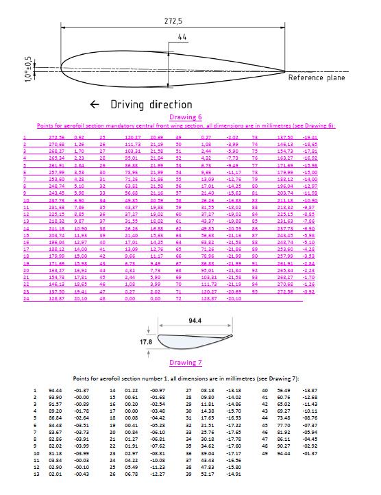
43
ARTICLE FIA FORMULA 4 TECHNICAL REGULATIONS
 ARTICLE 274 2018 FIA FORMULA 4 TECHNICAL REGULATIONS ARTICLE 1: DEFINITIONS 1.1 Formula 4 car 1.2 Automobile 1.3 Land vehicle 1.4 Bodywork 1.5 Wheel 1.6 Automobile make 1.7 Event 1.8 Weight 1.9 Racing
2018 FORMULA 3 TECHNICAL REGULATIONS
 2018 FORMULA 3 TECHNICAL REGULATIONS SUMMARY ARTICLE 1 : DEFINITIONS 1.1 Formula 3 car 1.2 Automobile 1.3 Land vehicle 1.4 Bodywork 1.5 Wheel 1.6 Automobile make 1.7 Event 1.8 Weight 1.9 Racing weight
2005 FORMULA ONE TECHNICAL REGULATIONS
 ARTICLE 1 : DEFINITIONS 1.1 Formula One Car 1.2 Automobile 1.3 Land Vehicle 1.4 Bodywork 1.5 Wheel 1.6 Complete wheel 1.7 Automobile Make 1.8 Event 1.9 Weight 1.10 Racing weight 1.11 Cubic capacity 1.12
2011 FORMULA ONE TECHNICAL REGULATIONS
 2011 FORMULA ONE TECHNICAL REGULATIONS ARTICLE 1 : DEFINITIONS 1.1 Formula One Car 1.2 Automobile 1.3 Land Vehicle 1.4 Bodywork 1.5 Wheel 1.6 Complete wheel 1.7 Automobile Make 1.8 Event 1.9 Weight 1.10
2015 FORMULA ONE TECHNICAL REGULATIONS
 2015 FORMULA ONE TECHNICAL REGULATIONS CONTENTS SUMMARY Pages ARTICLE 1 : DEFINITIONS 6-8 1.1 Formula One Car 1.2 Automobile 1.3 Land Vehicle 1.4 Bodywork 1.5 Wheel 1.6 Complete wheel 1.7 Automobile Make
2018 FORMULA ONE TECHNICAL REGULATIONS
 2018 FORMULA ONE TECHNICAL REGULATIONS PUBLISHED ON 19 DECEMBER 2017 CONTENTS SUMMARY Pages ARTICLE 1 : DEFINITIONS 6-8 1.1 Formula One Car 1.2 Automobile 1.3 Land Vehicle 1.4 Bodywork 1.5 Wheel 1.6 Complete
2018 CAMS MANUAL OF MOTOR SPORT
 2018 CAMS MANUAL OF MOTOR SPORT SPECIFICATIONS OF AUTOMOBILES 1st Category Racing Cars Formula Libre (Free Formula) For Race Events CONFEDERATION OF AUSTRALIAN MOTOR SPORT WWW.CAMS.COM.AU Modified Article
2019 FORMULA ONE TECHNICAL REGULATIONS
 2019 FORMULA ONE TECHNICAL REGULATIONS PUBLISHED ON 12 MARCH 2019 CONTENTS SUMMARY Pages ARTICLE 1 : DEFINITIONS 6 8 1.1 Formula One Car 1.2 Automobile 1.3 Land Vehicle 1.4 Bodywork 1.5 Wheel 1.6 Complete
2014 FORMULA 3 TECHNICAL REGULATIONS
 2014 FORMULA 3 TECHNICAL REGULATIONS SUMMARY ARTICLE 1 : DEFINITIONS 1.1 Formula 3 car 1.2 Automobile 1.3 Land vehicle 1.4 Bodywork 1.5 Wheel 1.6 Automobile make 1.7 Event 1.8 Weight 1.9 Racing weight
FORMULA ONE TECHNICAL REGULATIONS
 FORMULA ONE TECHNICAL REGULATIONS Amendments made on 23 June indicated thus SUMMARY ARTICLE 1 : DEFINITIONS 1.1 Formula One Car 1.2 Automobile 1.3 Land Vehicle 1.4 Bodywork 1.5 Wheel 1.6 Complete wheel
2014 FORMULA 4 HOMOLOGATION REGULATIONS
 2014 FORMULA 4 HOMOLOGATION REGULATIONS ARTICLE 1: Manufacturer registration ARTICLE 2: Chassis Homologation 2.1 Compliance with Technical Regulations 2.2 Price/cost requirements 2.3 Chassis homologation
1. GENERAL PRINCIPLES
 1. GENERAL PRINCIPLES 2. ELIGIBLE CARS 3. ENGINE 4. BODYWORK AND DIMENSIONS 5. WEIGHT 6. REPAIRS 7. DATA ACQUISITION 8. ELECTRICAL SYSTEM 9. GEARBOX - TRANSMISSION TO THE WHEELS 10. SUSPENSION AND STEERING
2010 FORMULA TWO TECHNICAL REGULATIONS
 2010 FORMULA TWO TECHNICAL REGULATIONS ARTICLE 1 : DEFINITIONS 1.1 F2 1.2 Sporting Regulations 1.3 Event 1.4 Set-up Sheet 1.5 Test 1.6 F2 Technical Manual ARTICLE 2 : GENERAL PRINCIPLES 2.1 Validity 2.2
U2010U FORMULA ONE TECHNICAL REGULATIONS SUMMARY
 U2010U FORMULA ONE TECHNICAL REGULATIONS ARTICLE 1 : DEFINITIONS 1.1 Formula One Car 1.2 Automobile 1.3 Land Vehicle 1.4 Bodywork 1.5 Wheel 1.6 Complete wheel 1.7 Automobile Make 1.8 Event 1.9 Weight 1.10
2019 CAMS MANUAL OF MOTOR SPORT
 2019 CAMS MANUAL OF MOTOR SPORT SPECIFICATIONS OF AUTOMOBILES 6th Category Other Vehicles Group 6SR Sports Racer CONFEDERATION OF AUSTRALIAN MOTOR SPORT WWW.CAMS.COM.AU Modified Article Date of Application
2009 FORMULA TWO TECHNICAL REGULATIONS
 2009 FORMULA TWO TECHNICAL REGULATIONS ARTICLE 1 : DEFINITIONS 1.1 F2 1.2 Sporting Regulations 1.3 Event 1.4 Set-up Sheet 1.5 Test 1.6 F2 Technical Manual ARTICLE 2 : GENERAL PRINCIPLES 2.1 Validity 2.2
FORMULA RENAULT SERIES-TECHNICAL REGULATIONS
 FORMULA RENAULT SERIES-TECHNICAL REGULATIONS Everything which is not explicitly authorized: In these regulations And in the technical bulletins relating to the FR 2.0 Evolution 4 published over the course
FIA Sportscar Championship 2001 Article 258A - Technical Regulations for Sports Racing Cars
 FIA Sportscar Championship 2001 Article 258A - Technical Regulations for Sports Racing Cars SUMMARY ARTICLE 1 : DEFINITIONS 1.1 Sports Racing Car 1.2 Automobile 1.3 Land Vehicle 1.4 Automobile make 1.5
SPECIFICATIONS OF AUTOMOBILES
 2017 CAMS Manual of Motor Sport SPECIFICATIONS OF AUTOMOBILES ALL VEHICLES IN RACES AND OTHER SPEED EVENTS MUST COMPLY WITH THE GENERAL REQUIREMENTS OF AUTOMOBILES (SEE GENERAL REQUIREMENTS FOR CARS AND
2016 FIM CEV REPSOL Moto2 TM TECHNICAL RULES (UPDATED: )
") 2016 FIM CEV REPSOL Moto2 TM TECHNICAL RULES (UPDATED: 13-01-2016) 2016 FIM CEV REPSOL Moto 2 TM TECHNICAL RULES Contents 1. Engine 2. Intake & Fuel System 3. Fuel tank and hoses 4. Airbox 5. Fuel and
2016 FIM CEV REPSOL Moto2 TM TECHNICAL RULES (UPDATED: 13-01-2016) 2016 FIM CEV REPSOL Moto 2 TM TECHNICAL RULES Contents 1. Engine 2. Intake & Fuel System 3. Fuel tank and hoses 4. Airbox 5. Fuel and
MODIFICATIONS TO AUTOMOTIVE DESIGN
 2018 CAMS PAYCE Australian Formula 4 Championship certified by FIA T 1. PREAMBLE Each automobile in the 2018 CAMS PAYCE F4 Australian Championship Certified by FIA (the Championship) shall comply entirely
REGISTRATION PROCEDURE FOR THE SUPPLY OF CARS IN THE 2014 and 2015 FIA FORMULA E CHAMPIONSHIP
 REGISTRATION PROCEDURE FOR THE SUPPLY OF CARS IN THE 2014 and 2015 FIA FORMULA E CHAMPIONSHIP PREAMBLE The FIA Formula E Championship ( The Championship ), designed to be the flagship of the FIA s sustainable
2018 CAMS MANUAL OF MOTOR SPORT
 2018 CAMS MANUAL OF MOTOR SPORT SPECIFICATIONS OF AUTOMOBILES 2nd Category Sports Cars Group 2A Sports Cars, open and closed CONFEDERATION OF AUSTRALIAN MOTOR SPORT WWW.CAMS.COM.AU Modified Article Date
2018 Lebanese Drift Championship Technical Regulations
 2018 Lebanese Drift Championship Technical Regulations Pro category: 1 - The safety equipment of all vehicles must comply with the FIA Appendix J as well as Appendix C of the National Sporting Code for
Index. 1. General Engine Exhaust Body Chassis Fuel Technical Exclusions... 9.
 Document Details Section IC Type Technical Specification Class 1/10 th 200mm Touring Car Release Date December 2010. Revised January 2011 Version 0.1 Initial extract from IFMAR 1/10th I.C. TRACK RACING
"LE MANS" PROTOTYPE ("LM"P900, "LM"P675 & "LM"GTP)
") "LE MANS" PROTOTYPE ("LM"P900, "LM"P675 & "LM"GTP) ART.1 - DEFINITIONS 1.1 - "LE MANS" PROTOTYPE ("LM"P / "LM"GTP) is a racing car with no production minimum required and meeting the prescriptions regarding
"LE MANS" PROTOTYPE ("LM"P900, "LM"P675 & "LM"GTP) ART.1 - DEFINITIONS 1.1 - "LE MANS" PROTOTYPE ("LM"P / "LM"GTP) is a racing car with no production minimum required and meeting the prescriptions regarding
LMP Technical Regulations
 2020 LMP Technical Regulations ARTICLE 1: DEFINITIONS 1.1 LE MANS Prototype LMP 1.2 Automobile 1.3 Land vehicle 1.4 Bodywork 1.5 Wheel centre line 1.6 Height measurements 1.7 Distances 1.8 Wheel 1.9 Complete
Section Type Class Release Date. th Onroad 1/8. Version 0.1. Updated weight Changes are. 2.2 Jan. Index Page 1 of 7
 Document Details Section Type Class Release Date Version 0.1 0.2 Dec 2008 1.0 May 2009 2.0 Dec 2010 2.1 Mar 2012 2.2 Jan 2013 IC Technical Specification 1/8 th Onroad December 2010. Revised January 2013.
Front Cover- Cold Fusion 2012 World Champions F1 Car, Brighton Secondary School. Australia. CONTENTS
 2013-14 US Technical Regulations Front Cover- Cold Fusion 2012 World Champions F1 Car, Brighton Secondary School. Australia. CONTENTS PREFACE SUMMARY OF MAIN REVISIONS FROM 2012 REGULATIONS... 4 ARTICLE
TECHNICAL FORM SEAT LEON CUP RACER MK3 1. GENERAL. Homologation N. Extension N. Model: LEON CUP RACER MK3. Make: SEAT SPORT
 Model: LEON CUP TECHNICAL FORM Certification valid as from: 26 MARCH 215 SEAT 1. GENERAL 11. MANUFACTURER SEAT 12. MODEL AND TYPE a) Model and type LEON CUP b) Typical chassis number VSSMK35F4XSSPXXXX
2013 JAF Grand Touring Car 300(JAF-GT300) Technical Regulations
 Technical Regulations") Article 1: Vehicle 1.1) Definition Grand Touring Car 300 Automobile having two seats at least and one or more doors on each side respectively for getting on and off. 1.2) Eligibility as an original vehicle
Article 1: Vehicle 1.1) Definition Grand Touring Car 300 Automobile having two seats at least and one or more doors on each side respectively for getting on and off. 1.2) Eligibility as an original vehicle
2018 Australian Rallycross Series - Vehicle Regulations 2018 RXA SERIES (AUSTRALIAN RALLYCROSS SERIES)
") 2018 RXA SERIES (AUSTRALIAN RALLYCROSS SERIES) VEHICLE REGULATIONS RXA has 2 primary groupings of vehicles Open and Production, with classes for 4wd & 2wd within those groupings. There is also a group
2018 RXA SERIES (AUSTRALIAN RALLYCROSS SERIES) VEHICLE REGULATIONS RXA has 2 primary groupings of vehicles Open and Production, with classes for 4wd & 2wd within those groupings. There is also a group
Technical Regulations
 F1 in Schools - 2014 World Finals Technical Regulations Technical Regulations 2015-2016 2013 - F1 in Schools Ltd. Page 1 of 27 3 September 2015 CONTENTS PREFACE SUMMARY OF MAIN REVISIONS FROM 2013 REGULATIONS...
NOMENCLATURE 2008 TECHNICAL REGULATIONS
 Parts for the FORMULA RENAULT 2.0 single-seaters are represented in this nomenclature and split into three categories: CATEGORY A No modifications are authorised. The parts in this category must remain
2019 FIA FORMULA 2 CHAMPIONSHIP TECHNICAL REGULATIONS
 2019 FIA FORMULA 2 CHAMPIONSHIP TECHNICAL REGULATIONS SUMMARY 1. GENERAL PRINCIPLES... 2 2. ELIGIBLE CARS... 2 3. ENGINE... 3 4. BODYWORK AND DIMENSIONS... 4 5. WEIGHT... 6 6. DATA ACQUISITION... 7 7.
2016 JAF Grand Touring Car 300(JAF-GT300) Technical Regulations
 Technical Regulations") 2016 JAF Grand Touring Car 300(JAF-GT300) Technical Regulations 2016 JAF Grand Touring Car 300(JAF-GT300) Technical Regulations Definition: Automobile having two seats at least and one or more doors on
2016 JAF Grand Touring Car 300(JAF-GT300) Technical Regulations 2016 JAF Grand Touring Car 300(JAF-GT300) Technical Regulations Definition: Automobile having two seats at least and one or more doors on
FEDERATION INTERNATIONALE DE L'AUTOMOBILE FIA FORMULA E CHAMPIONSHIP SUPPLY OF CARS
 FEDERATION INTERNATIONALE DE L'AUTOMOBILE FIA FORMULA E CHAMPIONSHIP SUPPLY OF CARS The Fédération Internationale de l'automobile (FIA) is the governing body for world motor sport and the federation of
Appendix 3 LHMC BMW MINI Technical Regulations
 INTRODUCTION. Appendix 3 LHMC BMW MINI Technical Regulations The following Technical Regulations are set out in accordance with the MSA specified format and it should be clearly understood that if the
2018 FIA FORMULA 2 CHAMPIONSHIP TECHNICAL REGULATIONS
 2018 FIA FORMULA 2 CHAMPIONSHIP TECHNICAL REGULATIONS SUMMARY 1. GENERAL PRINCIPLES... 2 2. ELIGIBLE CARS... 2 3. ENGINE... 3 4. BODYWORK AND DIMENSIONS... 4 5. WEIGHT... 5 6. REPAIRS... 6 7. DATA ACQUISITION...
TECHNICAL REGULATIONS FOR GT3 CLASS GT3 技术规则
 2017 年中国超级跑车锦标赛 TECHNICAL REGULATIONS FOR GT3 CLASS GT3 技术规则 * Adopted from FIA Appendix J Article 257a Technical Regulations for Grand Touring Cars Group GT3. * The English version shall be used should
Period: A - to Valid to FIA Class:
 Page1 Red and/or black dot entries: HISTORIC TECHNICAL PASSPORT VALID IN: & & This Technical Passport is not a certificate of authenticity, nor does it in any way verify the history of the car or its constituent
2019 CAMS MANUAL OF MOTOR SPORT
 2019 CAMS MANUAL OF MOTOR SPORT RALLY / ROAD GROUP G4 TECHNICAL REGULATIONS CONFEDERATION OF AUSTRALIAN MOTOR SPORT WWW.CAMS.COM.AU Modified Article Date of Application Date of Publication 1. PREAMBLE
TECHNICAL REGULATIONS RACING CLASSES. i. All vehicles must be a recognised model from a vehicle manufacturer.
 TECHNICAL REGULATIONS 2015- RACING CLASSES The technical regulations are designed to ensure the highest level of safety. All drivers and vehicles must comply with all written and oral directions of the
2018 CAMS MANUAL OF MOTOR SPORT
 2018 CAMS MANUAL OF MOTOR SPORT RALLY / ROAD GROUP G4 TECHNICAL REGULATIONS CONFEDERATION OF AUSTRALIAN MOTOR SPORT WWW.CAMS.COM.AU Modified Article Date of Application Date of Publication 1. PREAMBLE
2017 RXA SERIES (AUSTRALIAN RALLYCROSS SERIES)
") 2017 RXA SERIES (AUSTRALIAN RALLYCROSS SERIES) VEHICLE REGULATIONS RXA has 2 primary groupings of vehicles Open and Production, with classes for 4wd & 2wd within those groupings. There is also a group
2017 RXA SERIES (AUSTRALIAN RALLYCROSS SERIES) VEHICLE REGULATIONS RXA has 2 primary groupings of vehicles Open and Production, with classes for 4wd & 2wd within those groupings. There is also a group
REAL FEDERACIÓN ESPAÑOLA DE AUTOMOVILISMO
 Make: SEAT Sport TECHNICAL FORM TCN2 Certification valid as from: 08 APRIL 2016 Homologation form only valid for cars in Compliance with the SAFETY CAGE CERTIFICATE HES4441013 1. GENERAL 101. MANUFACTURER
2013 TECHNICAL REGULATIONS
 2013 TECHNICAL REGULATIONS Anything which is not explicitly authorized in: these regulations, the 2013 edition of the FORMULA RENAULT 1.6 Sverige Reglemente the 2013 edition of the FORMULA RENAULT 1.6
2014 JAF Grand Touring Car 500 (JAF-GT500) Technical Regulations
 Technical Regulations") 2014 JAF Grand Touring Car 500 (JAF-GT500) Technical Regulations Article 1: Vehicle 1.1) Definition Grand Touring Car 500 Automobile having two seats at least and one door on each side respectively for
2014 JAF Grand Touring Car 500 (JAF-GT500) Technical Regulations Article 1: Vehicle 1.1) Definition Grand Touring Car 500 Automobile having two seats at least and one door on each side respectively for
AUTO TEST. Observed Section Trials (OST) OST FORMULA
 OST FORMULA") AUTO TEST Observed Section Trials (OST) THIS SECTION DESCRIBES THE CONSTRUCTIONAL REQUIREMENTS FOR CARS TAKING PART IN WHAT ARE DESCRIBED AS OBSERVED SECTION TRIALS. THESE EVENTS WERE INTRODUCED TO AUSTRALIA
AUTO TEST Observed Section Trials (OST) THIS SECTION DESCRIBES THE CONSTRUCTIONAL REQUIREMENTS FOR CARS TAKING PART IN WHAT ARE DESCRIBED AS OBSERVED SECTION TRIALS. THESE EVENTS WERE INTRODUCED TO AUSTRALIA
Appendix 3. LHMC Supercar Technical Regulations 2015 FINAL. 1 of 5
 Appendix 3 LHMC Supercar Technical Regulations 5.1.1 INTRODUCTION. iii) fireproof balaclava The following Technical Regulations are set out in accordance with the MSA specified format and it should be
2018 CAMS MANUAL OF MOTOR SPORT
 2018 CAMS MANUAL OF MOTOR SPORT GENERAL REQUIREMENTS OF AUTOMOBILES Schedule N Fuel Tanks and Refueling CONFEDERATION OF AUSTRALIAN MOTOR SPORT WWW.CAMS.COM.AU Modified Article Date of Application Date
Porsche Carrera Cup Germany 2018
 Bulletin 1/2018 Supplement to the Regulations of 22.03.2018. The amendment is valid with immediate effect. (Changes/Additions are printed in italics) Part 2: Technical Regulations 1. Technical Series Regulations
2018 Technical Regulation for Indian Junior Touring Cars (TC-2)
") 2018 Technical Regulation for Indian Junior Touring Cars (TC-2) Member of Federation Internationale de l Automobile Federation Internationale de Motocyclisme Indian Olympic Association 2018 Specific Technical
2018 Technical Regulation for Indian Junior Touring Cars (TC-2) Member of Federation Internationale de l Automobile Federation Internationale de Motocyclisme Indian Olympic Association 2018 Specific Technical
2019 New Zealand Superbike Championship
 2019 New Zealand Superbike Championship Support Class Supplementary Regulations Covering: Superstock 600 (all rounds) Supersport 150 (Rounds 1, 4 & 5) Superstock 600: This class of motorcycle requires
RADICAL RXC COUPE SERIES
 RADICAL RXC COUPE SERIES ROAD AND RACE CARS RADICALSPORTSCARS.COM CONTENTS RADICAL RXC COUPE SERIES RADICAL RXC COUPE SERIES 01 RADICAL RXC 600R 04-05 RADICAL RXC GT3 06-07 RADICAL RXC GT 08-09 The RXC
2018 CAMS MANUAL OF MOTOR SPORT
 2018 CAMS MANUAL OF MOTOR SPORT SPECIFICATIONS OF AUTOMOBILES 2nd Category Sports Cars Group 2B Porsche 944 CONFEDERATION OF AUSTRALIAN MOTOR SPORT WWW.CAMS.COM.AU Modified Article Date of Application
Technical regulations for European Formula Ford to be entered in F1600 Championship Series
 Technical regulations for European Formula Ford to be entered in F1600 Championship Series ARTICLE 1: DEFINITIONS 1.1 Formula Ford car (Duratec) 1.2 Bodywork 1.3 Ground Clearance 1.4 Minimum weight 1.5
Porsche Mobil 1 Supercup 2018 DMSB Visa no. 805/18, approved on
 Bulletin 1/2018 Supplement to the Regulations of 22.03.2018. The amendment is valid with immediate effect. (Changes/Additions are printed in bold italic) Part 2: Technical Regulations 1. Technical Series
2019 CAMS MANUAL OF MOTOR SPORT
 2019 CAMS MANUAL OF MOTOR SPORT RALLY/ROAD HISTORIC RALLY CARS CONFEDERATION OF AUSTRALIAN MOTOR SPORT WWW.CAMS.COM.AU Modified Article Date of Application Date of Publication ELIGIBILITY REGULATIONS FOR
MONOPOSTO RACING Class Specification Formula Vee REVISED March 2008
 MONOPOSTO RACING Class Specification Formula Vee REVISED March 2008 VINTAGE FORMULA VEE (PRE-1970) These rules describe and specify Formula Vee racing cars as they raced in the 1969 racing season. This
SECTION 11 INTERMODAL EQUIPMENT
 SECTION 11 INTERMODAL EQUIPMENT ROA MANUAL SCHEDULE OF AMENDMENTS SECTION 11 AMENDMENT NUMBER PAGES AMENDED AMENDMENT SUMMARY DATE ISSUED TABLE OF CONTENTS Section Description Page No. 11.1 SCOPE... 11-1
DRAFT VTS. Approved for Racing
 DRAFT VTS Approved for Racing Vehicle Manufacturer: Audi Year and Model: 2009-2013 R8 This draft of the listed vehicle s VTS is posted with the specifications that we currently have for the vehicle. If
Modified Article Date of Application Date of Publication
 2018 CAMS MANUAL OF MOTOR SPORT SPECIFICATIONS OF AUTOMOBILES 5th Category Historic Cars Vehicle Eligibility Historic Specials CONFEDERATION OF AUSTRALIAN MOTOR SPORT WWW.CAMS.COM.AU Modified Article Date
PART 2 SCHEDULE GTR GTRNZ Race Series TECHNICAL REGULATIONS
 PART 2 SCHEDULE GTR GTRNZ Race Series TECHNICAL REGULATIONS 2017-2018 PREAMBLE The objective is to organize and promote competitive and close racing while maintaining regard for machinery and people, with
ASO HOMOLOGATION - TECHNICAL REGULATIONS FOR T4.2 TRUCKS FROM 1st of JANUARY 2018 ONWARDS
 ASO HOMOLOGATION - TECHNICAL REGULATIONS FOR T4.2 TRUCKS FROM 1st of JANUARY 2018 ONWARDS The yellow parts of the following regulations will be applied to the trucks homologated from the 1st of January
MSA Junior Rallycross Championship. Technical Regulations
 MSA Junior Rallycross Championship Technical Regulations The Following M.S.A. Vehicle & Technical Regulations apply, according to the 2014 MSA Yearbook: Section J5, Technical Regulations N6.1 to 6.14.3
Period: GR to 1971 valid to FIA Class: Fv/1
 Red/black dot entries: HISTORIC TECHNICAL PASSPORT VALID IN: RACING & & This Technical Passport is not a certificate of authenticity, nor does it in anyway verify the history of the car or its constituent
DRAFT Technical Regulations for Trucks result of La Paz/Breda TWG V
 TECHNICAL REGUALTIONS DAKAR Draft following La Paz / Breda TWG V1 09.05.17 Extinguishers All trucks must be equipped with two hand held fire extinguishers in the cabine. Permitted extinguishants: AFFF,
The new 911 GT3 R. Challenger.
 The new 911 GT3 R Challenger. Unstoppable. Only those who accept the challenge will unleash his strength. Only those who unleash his strength will conquer the race track. One thing is certain, you can
Changes are marked in RED text. Images and drawings used in this document AARCMCC Inc.
 Document Details Section IC On Road Type Technical Specification Class IC 1/8 th GT Onroad Release Date May 2014 Effective Date DRAFT Version 0.5 Initial version from Rob Parrington (NSWRCRCC) 0.6 Feb
F1 in Schools - World Finals Technical Regulations Revision 1
 F1 in Schools - World Finals Technical Regulations 2017 Revision 1 2017 - F1 in Schools Ltd. Page 1 of 32 2 June 2017 Front Cover INFINITE Racing, Greece, 2016 World Champions CONTENTS SUMMARY OF MAIN
SWIFT SPORT RALLYCROSS CHAMPIONSHIP. Technical Regulations
 SWIFT SPORT RALLYCROSS CHAMPIONSHIP Technical Regulations The Following M.S.A. Vehicle & Technical Regulations apply, according to the current MSA Yearbook: Section J5, Technical Regulations N6.1 to 6.14.3
WPMC HISTORIC CARS TECHNICAL RULES Pre-1990 FOR 2019 (161727/144) WPMC/HCTR/PRE90/2019 Rev C. Action Name Function Date
 WPMC/HCTR/PRE90/2019 Rev C. Action Name Function Date") FOR 2019 (161727/144) WPMC/HCTR/PRE90/2019 Rev C Review and Approval Record of the Present Document Action Name Function Date Drafted by Paul Dalton Vice Chairman 4 th October 2018 Checked by Jacques Blom
FOR 2019 (161727/144) WPMC/HCTR/PRE90/2019 Rev C Review and Approval Record of the Present Document Action Name Function Date Drafted by Paul Dalton Vice Chairman 4 th October 2018 Checked by Jacques Blom
Audi R8 LMS Cup Cup Car Technical Restrictions/Guidelines. PUBLISHED version 1.0: 11 May 2016.
 Audi R8 LMS Cup 2016 Cup Car Technical Restrictions/Guidelines PUBLISHED version 1.0: 11 May 2016. CONTENTS Specific Technical Restrictions and Guidelines.... 3 General Adjustments Information.... 3 TR1.
DRAFT VTS. Approved for Racing
 DRAFT VTS Approved for Racing Vehicle Manufacturer: Kia Year and Model: 2011 Optima This draft of the listed vehicle s VTS is posted with the specifications that we currently have for the vehicle. If a
REAL FEDERACIÓN ESPAÑOLA DE AUTOMOVILISMO
 TECHNICAL FORM TCN2 Certification valid as from: 08 APRIL 2016 Homologation form only valid for cars in Compliance with the SAFETY CAGE CERTIFICATE HES4441013 1. GENERAL 101. MANUFACTURER SEAT 102. MODEL
FORMULA STCC NORDIC 2018 TECHNICAL REGULATIONS UK
 FORMULA STCC NORDIC 2018 TECHNICAL REGULATIONS UK Anything which is not explicitly authorized in: these regulations, the 2018 edition of the FORMULA STCC NORDIC Reglemente the 2014 v1.1 edition of the
REGULATIONS AND SPECIFICATIONS FOR THE 2017 NATIONAL FORMULA 1600 DURATEC TECHNICAL REGULATIONS
 REGULATIONS AND SPECIFICATIONS FOR THE 2017 NATIONAL FORMULA 1600 DURATEC TECHNICAL REGULATIONS ARTICLE 1: DEFINITIONS 1.1 Formula Ford car (Duratec) 1.2 Bodywork and wings 1.3 Ground Clearance 1.4 Minimum
Vehicle Technical Specifications
 Vehicle Manufacturer: Volkswagen Year and Model: (99-05) Jetta Mk. 4 This specifications form was developed by SCCA Pro Racing and will be used by the TECHNICAL MANAGER to establish technical compliance
Porsche Mobil 1 Supercup 2018 DMSB Visa no. 805/18, approved on
 Bulletin 1/2018 Supplement to the Regulations of 22.03.2018. The amendment is valid with immediate effect. (Changes/Additions are printed in bold italic) Part 2: Technical Regulations 1. Technical Series
Partial Eligibility Models out of production 4+ years.
 Partial Eligibility Models out of production 4+ years. A vehicle will be in FULL ELIGIBILITY for World Challenge competition from the time it is homologated, until the end of the 4 th year after the body
REGULATIONS AND SPECIFICATIONS FOR THE 2017 WESTERN CAPE FORMULA M REGIONAL/CLUB CHAMPIONSHIP
 REGULATIONS AND SPECIFICATIONS FOR THE 2017 WESTERN CAPE FORMULA M REGIONAL/CLUB CHAMPIONSHIP 1. CONTROLLERS Will be the Western Province Short Circuit Committee. 2. AIM OF THE CHAMPIONSHIP To declare
DRAFT VTS Approved for Racing
 DRAFT VTS Approved for Racing Vehicle Manufacturer: Year and Model: Hyundai 2013-2014 Genesis This draft of the listed vehicle s VTS is posted with the specifications that we currently have for the vehicle.
Partial Eligibility. Models out of production 4+ years.
 Partial Eligibility Models out of production 4+ years. A vehicle will be in FULL ELIGIBILITY for World Challenge competition from the time it is homologated, until the end of the 4 th year after the body
Technical Regulations Open Wegrace Cup 2018 Version
 Technical Regulations Open Wegrace Cup 2018 Version 12-06-2018 Personal responsibility The participant is and always shall be chiefly responsible for keeping their motorbike in perfect condition and meeting
REAL FEDERACIÓN ESPAÑOLA DE AUTOMOVILISMO
 TECHNICAL FORM TCN2 Certification valid as from: 08 APRIL 2016 Homologation form only valid for cars in Compliance with the SAFETY CAGE CERTIFICATE HES4441013 1. GENERAL 101. MANUFACTURER SEAT 102. MODEL
TECHNICAL REGULATIONS 2019
 TECHNICAL REGULATIONS 2019 Version released on 17.12.2018 Page 1 of 8 0. TABLE OF CONTENT 1. ELIGIBLE VEHICLES... 2 2. GENERAL TECHNICAL REQUIREMENTS HISTORIC CARS... 2 3. SPECIFIC SAFETY REQUIREMENTS...
DRAFT VTS. Approved for Racing
 Vehicle Manufacturer: Year and Model: DRAFT VTS Approved for Racing This draft of the listed vehicle s VTS is posted with the specifications that we currently have for the vehicle. If a specification is
F1 in Schools - World Finals Technical Regulations 2018
 F1 in Schools - World Finals Technical Regulations 2018 2018 - F1 in Schools Ltd. Page 1 of 32 30 April 2018 Front Cover HYPERDRIVE, Australia, 2017 World Champions CONTENTS SUMMARY OF MAIN REVISIONS FROM
DISPLACEMENT: The maximum displacement that may be achieved in the Ski Superstock Class is 1500 cc.
 SKSS.1 SUPERSTOCK CLASS COMPETITION Competitors in this class are allowed modifications to gain maximum machine and engine performance while restricting the build costs by prohibiting aftermarket hulls
DRAFT VTS. Approved for Racing
 DRAFT VTS Approved for Racing Vehicle Manufacturer: Year and Model: SCION 2013 FR-S This draft of the listed vehicle s VTS is posted with the specifications that we currently have for the vehicle. If a
European Kawasaki Z Cup Technical Rules
 European Kawasaki Z Cup Technical Rules The following rules are intended to permit limited changes to the homologated motorcycle in the interest of safety. EVERYTHING THAT IS NOT AUTHORISED AND PRESCRIBED
1 REGULATIONS AND SPECIFICATIONS FOR THE 2015 SHORT CIRCUIT MOTORCYCLE 150 SENIOR CHAMPIONSHIP MSA WESTERN CAPE MOTORSPORT CIRCULAR WC 20/
 1 REGULATIONS AND SPECIFICATIONS FOR THE 2015 SHORT CIRCUIT MOTORCYCLE 150 SENIOR CHAMPIONSHIP MSA WESTERN CAPE MOTORSPORT CIRCULAR WC 20/2015 1. CONTROLLERS Will be the Western Province Short Circuit
2019 TECHNICAL REGULATIONS FOR THE HISTORIC PRODUCTION CAR GROUP 1 SALOON CARS (161684/144)
") 2019 TECHNICAL REGULATIONS FOR THE HISTORIC PRODUCTION CAR GROUP 1 SALOON CARS (161684/144) Permissions: With the exception of the under mentioned allowance, no other additions or modifications whatsoever
2019 TECHNICAL REGULATIONS FOR THE HISTORIC PRODUCTION CAR GROUP 1 SALOON CARS (161684/144) Permissions: With the exception of the under mentioned allowance, no other additions or modifications whatsoever
Vehicle Technical Specifications
 Vehicle: Ford mustang Boss 302 (202) and GT Class: GTS Vehicle Manufacturer: Year and Model: Ford Boss 302 (202) and GT This specifications form was developed by SCCA Pro Racing and will be used by the
Proposed Aerodynamic Rules Revisions
 Proposed 2015-2016 Aerodynamic Rules Revisions Revise the existing T 2.1 words to read as below. The Attachment at the end of this document shows the present words, deletions, amendments and additions.
2002 Rules & Regulations Cars On Ice Championship Auto Ice Racing
 I 2002 Rules & Regulations Cars On Ice Championship Auto Ice Racing 1. GENERAL: A. These rules and regulations supersede all rules and regulations previously published, and are, at date of publication,
2018 Technical Regulation for Indian Touring Cars (TC-1)
") 2018 Technical Regulation for Indian Touring Cars (TC-1) Member of Federation Internationale de l Automobile Federation Internationale de Motocyclisme Indian Olympic Association 2018 Specific Technical
2018 Technical Regulation for Indian Touring Cars (TC-1) Member of Federation Internationale de l Automobile Federation Internationale de Motocyclisme Indian Olympic Association 2018 Specific Technical
Classes INC. Northeast Snowmobile Racing INC SNOW DRAG RACING. Classes. Amateur: ( $15 Entry Fee + $5 Insurance Fee) Stock: 500, 600, 700, 800, Open
 Stock: 500, 600, 700, 800, Open") INC Northeast Snowmobile Racing INC Classes SNOW DRAG RACING Classes Amateur: ( $15 Entry Fee + $5 Insurance Fee) Stock: 500, 600, 700, 800, Open Improved Trail: 500, 600, 700, 800, Open Pro: ( $25 Entry
INC Northeast Snowmobile Racing INC Classes SNOW DRAG RACING Classes Amateur: ( $15 Entry Fee + $5 Insurance Fee) Stock: 500, 600, 700, 800, Open Improved Trail: 500, 600, 700, 800, Open Pro: ( $25 Entry
E/ECE/324/Rev.1/Add.78/Rev.2/Amend.3 E/ECE/TRANS/505/Rev.1/Add.78/Rev.2/Amend.3
 7 December 2017 Agreement Concerning the Adoption of Harmonized Technical United Nations Regulations for Wheeled Vehicles, Equipment and Parts which can be Fitted and/or be Used on Wheeled Vehicles and