USER MANUAL THEELECTRIC MOTO-BIKE
|
|
|
- Sydney Adams
- 5 years ago
- Views:
Transcription

1 USER MANUAL THEELECTRIC MOTO-BIKE
2 BULTACO MOTORS S.L., Madrid, Spain. All rights reserved. Printing and full or partial reproduction is prohibited without written permission from BULTACO MOTORS S.L.
3 3 Welcome bultaquista First of all, thank you for buying a Bultaco. We are proud to have your confidence. The new Brinco is a new and groundbreaking concept, the Moto- Bike that you will enjoy in a way you have never dreamed of before. For Bultaco innovation is not only to reach new technological goals, but also to offer new experiences. And Brinco is something completely new and ground-breaking; it is the result of the wanting to transport the Bultaco spirit to a new era, with a new language, whilst always being true to the classic brand values: passion, innovation, competition. worlds of the motorcycle and the bicycle: electric propulsion and the physical experience of pedaling, independently, or by combining the two systems. You decide at every moment how to maximise the perfect symbiosis between the handlebar and the pedals. Whether for short or medium distances, the Brinco is above all a friend like no other, for fun, games and for getting away from it all. Because Bultaco Brinco will take you where you want, where your heart desires, further and faster than where your legs alone would be able to go. With Brinco, Bultaco proposes a whole new way to understand and live the two wheels. A striking combination between the
4 4 USER MANUAL 1st Edition, Janaury 2016 Important Listed below is the most important information to enjoy your Brinco. We recommend that you read this user manual carefully before using your Brinco for the first time and consult it again every time you have any problems or questions. Your Brinco is a powerful and fun vehicle that can be used in many ways. Mishandling it may cause danger to life, health and possible risk of serious injury. Always ride with caution, using a helmet, gloves and protective clothing. Be aware that you will be moving in a fast and quiet vehicle, so be careful with people and animals around you. In this manual we will give you advice and warnings so you can take full advantage of your Brinco as keep it as good as new. That is why we recommend using original parts /accessories and getting them fitted at a Bultaco Motors Dealer. You must pay very close attention to our safety warnings, because we consider them essential to prevent falls and injuries. If after reading this manual you have any doubts or need further information, please contact your Bultaco Motors Dealer. This user manual: -Contains important technical and safety information. -Describes generally the most important features of your Bultaco. -It is intended for private users, and is not prepared for use by professional staff. -Reflects the version described at the time of printing, so there may be small differences, due to the continuous improvement of our Bultaco products. All information in this manual is non-binding. Bultaco Motors S.L. reserves the right to: -Introduce, without notice and without disclosing the reasons, changes in the technical data, maintenance services, colors, design, equipment and the vehicle materials. -Adapt their vehicles to local conditions in certain markets and to stop production of a particular model without prior notice. Bultaco Motors S.L. assumes no liability in connection with difficulties in the availability of vehicles, with differences between images or descriptions and the particular vehicle, nor errors or omissions in this manual. The models portrayed partly contain special equipment which is not standard.
5 LEGAL PROVISIONS 5 WARNING! INFORMATION CHANGES MADE TO THE VEHICLE MAY AFFECT YOUR SECURITY AND PRODUCE INJURIES TO PEOPLE Any modification made to the vehicle without Bultaco Motors S.L. s approval will have the following effects: - Loss of warranty rights granted by the manufacturer. - Possible need to obtain another driving licence. - Risk of accidents and serious injuries BEFORE USING YOUR BRINCO REVIEW ANY LOCAL REGULATIONS RELATED TO THE USE OF ELECTRICAL AND MOTOR VEHICLES. THE BRINCO, AS IT DOES NOT HAVE THE REQUIRED APPROVAL FOR CIRCULATION, IS NOT SUITABLE FOR USE ON PUBLIC ROADS. Contact one of our Bultaco Motors Dealers if you have any questions. For your information, the applicable laws may include some of the following items: - Age requirement for vehicle use. - Equipment required to travel on certain roads. - Need for a special licence to use the vehicle. - Areas of restricted use for the vehicle.
6
7 INDEX 7 1. GENERAL SAFETY 1.1. General warnings Operational Safety Locating Power Components VEHICLE DESCRIPTION 2.1. Presentation Location of Components Handlebar Controls Dashboard Dashboard Configuration Power Control Button Identification Numbers Technical specifications Dimensions GENERAL OPERATION 3.1. Prior Checks Battery Charge Removing the Battery Charging the Battery Starting your Brinco Starting card /wristband copy During the ride Gear shift / Transmission Stopping your Brinco Instructions for Use Directions for Parking MAINTENANCE 4.1. Adjusting the Rear Suspension: Shock Absorber Adjusting the Front Suspension: Fork Brakes Wheels and Tyres Transmission: Chain and Bottom Bracket Cleaning Torque Settings Maintenance Table TROUBLESHOOTING 5.1.Troubleshooting WARRANTY 6.1. General Warranty Warranty Exclusions Management of Warranty Consultations Warranty Rights of the Owner Warranty Term 69

8 1.GENERAL WARNING
9 1.1. General Warning 9 You are the only person responsible for the use of this motorbike. Do not allow other people to ride the vehicle without having received appropriate instructions and / or reading this manual. Remember that neither the seller of this Brinco nor Bultaco Motors S.L. can be hold responsible for the misuse or negligence when using the Brinco. Your Brinco is not a competition vehicle and it is not designed for such use. Thus, its use in competition will mean the loss of the warranty provided by Bultaco Motors S.L. INDICATES THE EXISTENCE OF POSSIBLE DANGERS TO THE VEHICLE OR OTHER PARTIES. Follow the inspection and maintenance periods indicated here, that along with good riding technique will help you to enjoy your Binco safely and reliably. Make sure you understand the importance of checking all vehicle components carefully before riding. Before each trip, you should check the condition of the vehicle in accordance with section 3.1 as well as the battery charge level and connection. Remember that the power components of your Brinco should be handled only by authorised personnel of Bultaco Motors S.L. [See section 1.3]. WARNS OF HEALTH HAZARD AND POSSIBLE RISKS OF SERIOUS INJURY. Throughout these instructions you will find different types of indications. The symbols used are described in the next section. With these symbols we are letting you know that if if you do not follow them or comply with them, you will not be using your Brinco correctly or it may not work properly. Remember that, in addition to the loss of warranty, you will endanger yourself and other people around you. INDICATES THE EXISTENCE OF USEFUL TIPS AND SPECIAL INFORMATION.
10 1.2. Operational Safety 10 Listed below are several things to keep in mind regarding the operation of the vehicle: Whenever you do not use your Brinco, put the engine stop button in the OFF position [See section 2.3]. It is easy to forget when it is on and an accident could occur when getting on or off the bike. Similarly, to move the vehicle without riding it, make sure the engine stop button is in the OFF position [See section 2.3]. ALWAYS USE THE ORIGINAL BULTACO BATTERY CHARGER. To get the most out of the battery, recharge it immediately after each ride. If you leave the battery discharged it could be damaged. THE BATTERY MAY BE DAMAGED IF FULLY DISCHARGED. If you are not going to use the vehicle for more than 30 days, we recommend unplugging the battery from the motorbike and keeping it connected to the charger during this period. If you cannot keep it plugged in, we recommend that a full battery charge is done at least once every 30 days. Leave the battery plugged in whenever possible, always use the cable / charger supplied by us, it has been designed to be used with the electrical components of this motorbike [See section 3.2]. If you do not follow the instructions for charging and storing the battery described in these operating instructions you will lose the warranty on it. These guidelines have been rigorously tested to ensure maximum efficiency and durability of the battery. FOLLOW THE INSTRUCTIONS FOR BATTERY CHARGING AND STORAGE.

11 1.3. Locating Power Components 11 Power Zones The power components handle voltages up to 59V that can be health hazards and potential risks of serious injury: POWER PARTS WILL REMAIN ACTIVE FOR A PERIOD OF TIME AFTER THE VEHICLE HAS BEEN SWITCHED OFF. Their handling (except for assembly / disassembly and charging the battery and engine disconnection to handle the rear wheel) must only be carried out by a Bultaco Motors Dealer. Any damage to any of the power components must be repaired immediately by a Bultaco Motors Dealer. NEVER CUT CABLES OR HANDLE THE POWER COMPONENTS.

12 2.VEHICLE DESCRIPTION
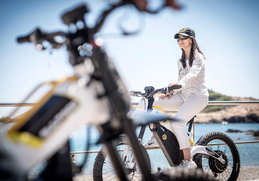
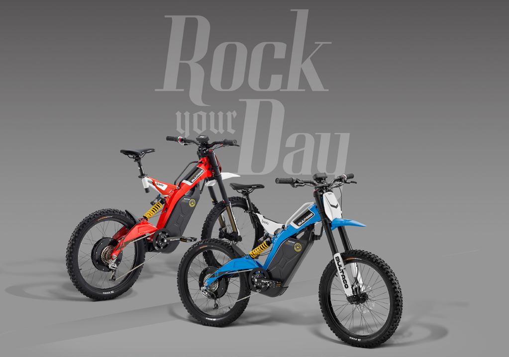
13 2.1. Presentation 13 The Bultaco Brinco surprises with its innovative design, technology and the effectiveness of each of its elements. The Bultaco engineering and design teams have worked together to create the first Motorbike with a spectacular, very sporty and beautiful result. From the first time you see a Bultaco Brinco it is clear that it is something new and uncomparable to everything we knew before. Its features might ressemble those of a competition mountain bike, a dirt bike, a crossbike or an urban trail bike, but its design and the engineering solutions that define it reveal it as a special machine that exceeds the established labels. Brinco opens the door to multiple riding choices, offering everyone the opportunity to decide how to equalise the best motor / pedal combination for their Brinco under every situation: engine, independent pedalling or a combination of both. Thanks to its impressive torque of 60Nm, weighing just 39 kg and with a range of up to 100 km, the Brinco offers pure fun. Brinco is 100% Bultaco enthusiasm for all ages. Brinco is hyperlight, hyperconnected and hyperfun.
14
![2.2. Location of Components 15 1 Three-phase Permanent Magnet Motor. [See section 2.9] 2 Planetary gearbox [See section 3.](/docs-images/95/124592835/images/15-0.jpg "5] Possibility of Change: Overdrive - Low Range Gearbox (2) by touching the button located at the base of the rod: Pressing with the right foot it goes to the gear ratio of higher speed.")
15 2.2. Location of Components 15 1 Three-phase Permanent Magnet Motor. [See section 2.9] 2 Planetary gearbox [See section 3. 5] Possibility of Change: Overdrive - Low Range Gearbox (2) by touching the button located at the base of the rod: Pressing with the right foot it goes to the gear ratio of higher speed. 3 DC / AC Three Phase Controller [See 2.9] 4 Power Cell Li-Ion Matrix Battery [See 2.9] 5 Battery Connector [See 3.2.1] Disconnect your battery power system quickly with a simple twist of the connector in a counterclockwise direction. 9 6 Battery safety lock [See 3.2.1] The battery has a single key safety lock for each vehicle. The battery will be attached to the chassis and the key is required to remove it Seat Adjustment [See 2.9] With the standard sub-chassis, the seat can reach a minimum height of 1 metre from the ground (cutting the seat bar). There is also the option to purchase a LowSeat sub-chassis that allows you to further reduce the seat height. 8 Rear Suspension Adjustment [See 4.1] Front Suspension Adjustment [See 4.2]
![2.3. Handlebar Controls 16 3 1 2 4 7 6 5 1 2 3 4 Dashboard [See 2.3] Front brake lever [See 2.9-4.3] CHECK THE BRAKE POSITION PROPERLY. The front brake lever is on the right handlebar grip.](/docs-images/95/124592835/images/16-0.jpg "Rear brake lever [See 2.9-4.3] CHECK THE BRAKE POSITION PROPERLY. The rear brake lever is on the left handlebar grip.")
16 2.3. Handlebar Controls Dashboard [See 2.3] Front brake lever [See ] CHECK THE BRAKE POSITION PROPERLY. The front brake lever is on the right handlebar grip. Rear brake lever [See ] CHECK THE BRAKE POSITION PROPERLY. The rear brake lever is on the left handlebar grip. Throttle control Always make sure that the accelerator returns correctly to its initial position when you release it after accelerating before switching ON your Brinco Stop button [See 3.3] ALWAYS check that the vehicle is turned off after use. Button in OFF position. Power Control Button [See 2.6] It allows you to select and set a cruise power level so that constant electric power is used without operating the throttle. Shifter [See 3.5] 9-speed gear ratio.
 [See 2.5] Driving mode: ECO - SPORT TOUR [See 4.5-2.9] To the right of the mode the instantaneous power is shown in W.")
17 Dashboard WHENEVER THE DASHBOARD IS ILLUMINATED YOUR BRINCO WILL BE ON BUT IT ONLY WILL BE IN RUNNING CONDITION WHEN THE STOP BUTTON IS ON Speedometer (km/h - mph) [See 2.5] Driving mode: ECO - SPORT TOUR [See ] To the right of the mode the instantaneous power is shown in W. 7 Warning Indicator [See 5] This light flashes when you turn on your Brinco and testing is being performed. Once testing has finished, the light will remain on until the motorbike is put in driving position (and the power button is ON) Battery Level When the battery level falls below 2 bars (22% battery), the low battery indicator will be shown. Odometer / Trip [See 2.5] In-use Indicator Will be alight when the Brinco is powered on. Low battery Indicator Will be alight when 2 or less battery bars are displayed. Normally, the light will be off. If this light is on it will mean that something on your Brinco is not working properly, that it is in self-protection mode or that a system failure has been detected. 8 MODE Function [See 2.4] 9 10 SET function [See 2.4] NFC Antenna to lock/unlock your Brinco. The antenna is connected to the Biker Manager, a system to start the vehicle by means of a pilot wristband/card.
18 2.5. Dashboard Configuration 18 COMMUTATION ENTRE KM/H ET MPH CHANGING DRIVING MODE Press the MODE and SET buttons simultaneously for more than 4 seconds. The measurement unit will change automatically. ECO MODE TOUR MODE SPORT MODE The riding mode when starting the vehicle will be ECO by default. The riding mode can be changed by pressing with a short press the MODE button. The viability of the mode change takes into account the following parameters: - Battery level between 2 bars (22%) - 8 bars (100%) Changement possible ÉCO TOUR SPORT to to to TOUR SPORT ÉCO - Battery level from 1 bar (11%) - 2 bars (22%) It allows change from ÉCO to TOUR - Battery level between 0 bars (0%) - 1 bar (11%) Only allows ECO mode
19 19 ODOMETER - TRIP 1 - TRIP 2 SUMMARY OF FEATURES This option can be changed by pressing the MODE button with a long press for more than 4 seconds until the display shows ODO - TRIP1 - TRIP2. The TRIP can be reset once selected by pressing the SET button for more than 2 seconds. Display Long press MODE (4 sec.) Dashboard buttons Short press MODE Long press SET (2 sec.) Long press MODE & SET ODO TRIP 1 - TRIP 1 TRIP 2 Change driving mode TRIP 1 reset Change measurement units TRIP 2 ODO TRIP 2 reset
20 2.6. Using the POWER CONTROL Button 20 The Power Control button [See 2.3] allows you to select and maintain the same level of power during your ride. To use the power button, you accelerate to achieve the desired power level (you can check its value on the dashboard) and then press the Power Control button to maintain that power level. Once this is done you can stop accelerating and the vehicle will continue its ride at the desired power. RIDE WITH EXTREME CAUTION WHENEVER POWER CONTROL IS ON. To turn off Power Control you just need to press any brake lever or press the Power Control button again. When in the Power Control mode you can accelerate to exceed the value of cruising power if necessary. In normal riding mode (with Power Control off), you can view the instantaneous power level on the display, at the right of the driving mode ( POT in the image shown). Once the cruise power is selected it will be set and displayed on the dashboard display until Power Control is turned off. POWER CONTROL WILL BE DEACTIVATED BY: - PUSHING THE POWER CON- TROL BUTTON - PRESSING ANY OF THE BRAKE LEVERS


21 2.7. Identification Numbers 21 1 Vehicle Identification Number VIN (Serial number) The VIN is a 17 digit number that is printed on the right side of the steering tube. 1 2 Battery Identification Number On the lower side of the battery there is a warranty seal with safety instructions and its identification number. 3 Controller Identification Number The controller identification number is engraved on the chassis aluminum support plate. 2 4 Engine Identification Number The engine identification number is engraved on the left side of the engine. 3 4 DO NOT CHANGE ANY OF THE IDENTIFICATION NUMBERS OF YOUR BRINCO NOR BREAK THEIR SAFETY SEALS, OTHERWISE YOU WILL LOSE YOUR WARRANTY.
22 Technical Specifications ENGINE POWER SYSTEM Type Three-phase permanent magnet brushless motor. (Maximum power 2.0kW). PMAC Brushless radial flow with passive air cooling with integrated speed and temperature sensors. Three-phase DC/AC controller (50V-55A Maximum power) Type Nominal Capacity Lithium-ion battery cells with integrated management system Power Cell Li-Ion Matrix (1.3 kwh) Ah Control Unit Three selectable driving modes: SPORT: 2 kw TOUR: 1.5 kw ECO 0.9 kw Regenerative deceleration Self-diagnostic system Charger Portable with high performance specifically for the Bultaco Brinco Li-Ion Matrix Power Cell. Power 465W Input 110 VAC VAC Output 58.1 VDC / 8A Max speed without assisted pedalling > 60 km/h Charging time (standard) 0%-100% - 3.5h 0%-95% - 3h 0%-80% - 2h
23 23 RANGE vv CHASSIS / SUSPENSIONS / BRAKES Road - Mountain ECO mode (average speed 25 km/h) up to 100km Frame Swing arm Light aluminum alloy, central spine type. Mono-Shock in light aluminum alloy. Front suspension travel 180 mm. Pedalling TRANSMISSION Manual 9 synchronised speed grip + Overdrive Reduction system with pedals. Rear suspension travel Front brake Rear brake 217 mm. Hydraulic system with 4-piston caliper and 203mm disc diameter. Hydraulic system with 2-piston caliper and 203mm disc diameter. Engine Direct Drive System Front tyre Off Road Tyre 24x3 [ ERTRO] Rear tyre Off Road Tyre 24x3 [ ERTRO] Front wheel Aluminum - 24 [25x507 TYPE C ERTRO] Rear wheel Aluminum - 24 [25x507 TYPE C ERTRO] Front suspension Rear suspension Inverted telescopic fork with adjustable pre-loaded spring and hydraulic extension. Aluminum mono-shock with separate tank. Adjustable, pre-loaded, hydraulic spring in compression and extension.
24 2.9. Dimensions º à ,
25 25 DIMENSIONS WEIGHTS Distance between wheel centers Seat height Release angle Base height to ground Total length Width Height 1,200.7 mm Vehicle (without battery) 31.5 Kg 1, ,003.6 mm Vehicle (with battery) 39.5 Kg 23.2 o Load Capacity 100 Kg mm 1,856.7 mm 760 mm 1,094.2 mm

26 3.GENERAL OPERATION
27 3.1. Prior checks 27 To make sure your Brinco is ready for use, you must perform the following checks: 1. Adapt the seat and handlebar height to your size so that they are in a safe and comfortable position. Make sure all items are well secured and that they are in the proper position. 2. Adapt the position of the brake levers so that you can always reach them easily. Make sure you are very familiar with the brake lever configuration (front brake to the right / rear brake to the left). [See 4.3] 3. Check the operation of the brakes. Press each brake lever individually while pushing the vehicle to check that the wheels lock completely. [See 4.3] DETERIORATED TYRES OR TYRES WITHOUT THE CORRECT PRESSURE CAN CAUSE THEM TO BURST UNEXPECTEDLY AS WELL AS A LOSS OF CONTROL OF THE VEHICLE. LOW PRESSURE WILL REDUCE THE RIDE RANGE SIGNIFICANTLY. 4. Check tyre condition and pressure periodically [See 4.4] 5. With the engine stop button in the off position [See 2.3] operate the accelerator control and release it to check that it returns to its initial position. 6. Check the condition of the sprockets, transmission plate and the chain lubrication [See 4.5]. Make adjustments if necessary. AFTER A FALL OR A MOTO-BIKE ROLLOVER, YOU MUST PERFORM A COMPREHENSIVE REVIEW BEFORE RIDING THE VEHICLE AGAIN AND VISIT A BULTACO MOTORS DEALER FOR A PROFESSIONAL INSPECTION.
28 28 7. Check the electrical system of the vehicle (battery, motor, controller, power wiring). All wires and elements must be in perfect condition and external connectors positioned correctly. 8. Check the battery charge level on the dashboard. [See 2.4]. If after reading these instructions you still have questions, contact your Bultaco Motors Dealer, who will be happy to help. NEVER CUT WIRES OR MODIFY ANY OF THE POWER COMPONENTS. IT CAN CAUSE SERIOUS INJURY. BATTERY AND CHARGER The battery incorporates a Management System (BMS) that monitors the cell s status and optimises charging to provide maximum performance and a longer lifespan. THE BATTERY HAS A SAFETY SEAL WITH SAFETY WARNINGS. BEING A POWER ELEMENT, IT CAN ONLY BE HANDLED BY A BULTACO MOTORS DEALER. Fully charge the battery before the first use. During charging, the charger LED light will be yellow. When the battery is fully charged, the charger LED light will turn green, meaning that the battery is ready for use. The battery range may vary considerably depending on conditions such as the slope of the road and pedalling. [See 3.4] If during a long trip the level of the battery charge drops to 25% of the total capacity (2 bars on the dashboard), the battery management system will switch to ECO mode automatically. The system will be deactivated before a complete battery discharge can occur. IF THE SAFETY SEAL IS BROKEN IT WILL RESULT IN THE AUTOMATIC LOSS OF THE WARRANTY. FULLY CHARGE THE BATTERY BEFORE FIRST USE.
.")


29 3.2. Battery Charge 29 Connect the Bultaco original charger to the battery and the power outlet (240 V AC 50Hz / 110 V AC 60Hz). Remember that this can be done with the batteries on the vehicle or with them removed, as shown below. ALWAYS CHARGE THE BATTERY WITH THE ORIGINAL BULTACO BATTERY CHARGER Removing the battery 1. Unplug the power cord from the battery by hand turning the connector housing a quarter turn counterclockwise and pulling it out carefully. 2. Enter the key provided by Bultaco to unlock the battery safety lock. 3. Remove the retaining screw while firmly holding the battery pack. You can loosen it by hand or with a 5 Allen key. 4. Hold the battery firmly and rotate it slightly on its base to release the chassis anchorage


30 30 5. Once the battery is disconnected from the lower support, lift the battery to fully remove it. 6. Make sure the battery is placed horizontally, in a safe position close to the socket. Connect the charger to the battery and to the electrical network. Charging will start automatically. 7. When you plug the male connector to the battery, either the moto-bike s or the charger s connector, be careful not to damage it. Note that both connectors, male and female, have notches on the inside that must match. Introduce the male connector into the female connector fully and then rotate its housing clockwise a quarter turn to secure it in place. 5 FEMALE MALE 8. Once the charger is connected, a verification test will be done before it starts to charge automatically. The next section explains what the charger s warning lights mean. [See 3.2.2] BEFORE REMOVING THE BAT- TERY ALWAYS MAKE SURE YOUR BRINCO IS DISCONNECTED. TO REASSEMBLE THE BATTERY, FOLLOW THE STEPS DESCRIBED IN REVERSE ORDER. IF YOU WANT TO CHARGE YOUR BATTERY WITHOUT REMOVING IT FROM THE VEHICLE, YOU MUST FOLLOW ONLY STEPS 1 AND 6. IT IS RECOMMENDED THAT THE BATTERY SCREW IS TIGHTENED USING A 5 ALLEN KEY PROVIDED IN OUR TOOLKIT, TO PREVENT THE SCREW FROM COMING LOOSE.
31 Battery Charge Battery charging CHARGER INDICATOR The battery is charging. The battery is fully charged. Failure during charging. Check charger instructions. Once the charger is connected, the charging process starts automatically after 15 seconds. Do not forget to turn off or unplug the charger after use. To do this you have to press the button for 2-3 seconds and disconnect it from the network. ONCE THE BATTERY IS CHARGED (GREEN INDICATOR), FIRST DISCONNECT THE CHARGER FROM THE NETWORK AND THEN DISCONNECT THE BATTERY CHARGER. Charging can be paused with a short press of the button. The green and yellow LEDs will light alternately. In this state the power socket cannot be disconnected. To continue charging make a short press on the button - or wait for 1 minute. DO NOT INTERRUPT THE CHARGING PROCESS UNTIL THE BATTERY IS FULLY CHARGED. INTERRUPTING THE BATTERY CHARGING PROCESS COULD CAUSE A LOSS OF CAPACITY OR PREMATURE BATTERY FAILURE.
32 32 Even if the battery is fully charged, if it is still plugged in the charger will check the charge status periodically to ensure that the charge is complete. If the charger does not indicate that the battery is fully charged, it will still try to charge it fully. If you will not use the vehicle for long periods of time you must disconnect the battery from the moto-bike. We recommend that the Brinco battery is kept connected to the charger if it is not going to be used for more than 30 days. In case you decide not to keep the battery connected to the charger, make sure you remember to charge the battery for at least two hours every 30 days. RECHARGE THE BATTERY REGULARLY TO IMPROVE BATTERY LIFE AS MUCH AS POSSIBLE AND TO OPTIMISE ITS PERFORMANCE. MAXIMUM BATTERY PERFORMANCE WILL NOT BE ACHIEVED UNTIL YOU HAVE MADE AT LEAST 5 CYCLES OF CHARGE AND DISCHARGE THE BATTERY MAY BE DAMAGED IF FULLY DISCHARGED (BELOW MINIMUM LEVEL OF USE).
33 Battery charging LED INDICATOR LIGHTS Operating condition during charging < 80% > 80% 100%! Comments Start with total discharge Flashing Main charge X Further load X Final charge / charge conservation X
34 34 LED INDICATOR LIGHTS Operating condition during error < 80% > 80% 100%! Error number Missing battery X 1 Battery failure Flashing X 2 Time failure X X 3-4 Regulating failure X X Temperature failure X X 6 Error number TROUBLESHOOTING Procedure 1,2,3,4 Check battery and battery wiring 6,11-13 Ask for the charger to be checked at your Bultaco Motors Dealer
 until the dashboard lights up [See 2.4 ].")
35 3.3. Starting your Brinco 35 After performing the checks described in paragraph , your Brinco is ready to start riding. To start it you must follow the procedure descibed below: 1. Place the Bultaco card or wristband in the front of the dashboard where the NFC antenna is (both dashboard and wristband/card must have physical contact) until the dashboard lights up [See 2.4 ]. YOU WILL RECEIVE A MASTER CARD WITH YOUR BRINCO WHICH WILL ALLOW YOU TO CREATE COPIES OF YOUR CARD / WRISTBAND [SEE 3.3.1] 2. When you turn the system on your Brinco will perform a test and an intermittent warning light will flash on the dashboard. Clarification: If the power button is ON, the warning light will be illuminated permanently and you must operate any of the brakes before you set off.
36 36 3. Once the check is finished the warning light on the dashboard will turn off and you have to put [See 2.4] the power button in the ON position. [See 2.3] OFF ON USE THE THROTTLE CONTROL WITH CARE. THE LACK OF NOISE FROM THE MOTOR MAY BE MISLEADING WITH REGARDS TO THE VEHICLE S POWER. Press 4. With the button in the ON position, press one of the brake levers [See 2.3]. Once the warning indicator is off [See 2.4], you can speed up and enjoy the Brinco ride.


37 Starting Card / wristband Copy We will provide you with a Brinco Master card. This card allows you to make up to 10 card/ wristband copies. REMEMBER THAT YOU CAN MAKE 10 COPIES FROM YOUR MASTER CARD. To make a copy from your Master card you should purchase a blank card or wristband at your Bultaco Motors Dealer and follow these steps: 1. Turn on your Brinco using the Master card. 2. Turn off your Brinco using the blank card / wristband. At this time your copy will be complete. 3. Turn on your Brinco again with the new copy of the card / wristband to check it works properly. IF YOU LOSE YOUR MASTER CARD GO TO YOUR BULTACO MOTORS DEALER.
 to change to TOUR or SPORT mode [See 2.5].")
38 3.4. During the ride 38 The Brinco is designed for combined riding by both pedalling and with electrical assistance from the engine incorporated into the rear wheel. By default, the system is put in ECO mode after starting up. Press the MODE button (short press) to change to TOUR or SPORT mode [See 2.5]. The prolonged use in non-combined mode (without pedalling), at high engine torque in steep terrain, as well as riding for a long time in SPORT mode will lead to greater energy consumption that could cause the engine, controller or battery to overheat. In these situations a self-protection system will be automatically activated which progressively reduces the maximum power available as a function of the temperature and external stress. IF THE PERFORMANCE DEMAND EXCEEDS THE PHYSICAL LIMITS OF THE BRINCO, THE POWER WILL BE TEMPORARILY DISCONNECTED UNTIL THE SYSTEM TEMPERATURE DROPS SUFFICIENTLY ENOUGH BEFORE RESTARTING THE VEHICLE. Activation of this self-protection system is displayed on the dashboard throughwarning lights for the various phases: - A first phase with a slow flashing light will slightly reduce performance - A second phase with a rapid flashing light that will further reduce performance. - A third phase with a continuous light that will stop the vehicle. If the flashing warning light appears, it is recommended that the Brinco power level be reduced and assisted by pedalling so that the warning level with a continuous light, that would mean the vehice coming to a complete stop, is not reached. If this state is reached the self-protection system will completely disconnect the engine s power source. You should wait for some time until the temperature returns to normal operating values before starting the vehicle again. ECO MODE IS THE MOST RECOMMENDED FOR USE IN AREAS WITH STEEP, LONG SLOPES. IF YOU ONLY USE YOUR BRINCO IN ELECTRIC MODE, CONSUMPTION AND TEMPERATURE WILL INCREASE AND RIDING RANGE WILL DROP. PLAN YOUR ROUTE IN ADVANCE.
.")

39 Gear shift / Transmission To get the most out of pedalling, your Bultaco Brinco has a transmission comprised of a planetary low range gearbox and a cassette of 9 sprockets. By combining the different gear ratios you will get the performance you need at all times. OVERDRIVE - LOW RANGE GEARBOX CASSETTE OVERDRIVE: High gear ratio (faster). It is operated by pressing the button on the base of the right foot rod. LOW RANGE GEARBOX: Low gear ratio (increased torque requirement). It is operated by pressing the button on the base of the left foot rod. It can be done with the vehicle in motion. 9 sprockets selectable from the handlebar gear shifter: HIGHER SPEED 1 - Large sprocket for short gear ratio (increased torque requirement). HIGHER TORQUE 9 - Small sprocket for long gear ratio (high-speed situations). COMBINATIONS OVERDRIVE + Sprocket 9 Maximum Speed LOW RANGE GEARBOX + Sprocket 1 Maximum Torque
40 Stop your Brinco 1. Release the accelerator and brake the vehicle until it stops. 2. Press the stop button and put it in the OFF position. Interchangeably, you can disable your Brinco by placing your card or wristband on the front of the dashboard until the dashboard turns off. THE STOP SWITCH MAY BE USED IN AN EMERGENCY IF YOU WANT TO TURN OFF THE ENGINE. GET THE MOST OUT OF THE BATTERY, RECHARGE IT IMMEDIATELY AFTER EACH RIDE. MAKE SURE THE VEHICLE IS COMPLETELY TURNED OFF AFTER DISABLING IT THE BATTERY MAY BE DAMAGED IF FULLY DISCHARGED.
41 3.7. Riding instructions 41 From Bultaco we would like to give you the following riding tips: Avoid improper braking. It can cause serious damage to the brakes and even make you lose control of the vehicle while riding. Do not ride under the influence of alcohol or any drugs or medicines that may alter your reaction time. Always use proper equipment including helmet, footwear, gloves, etc. 4 Do not hang objects from the handlebar or other vehicle parts. Use the accessories provided by Bultaco for transporting packages Do not carry passengers. The Brinco is designed to transport one person. Never ride the vehicle when being towed. When on a descent, remember to keep your weight towards the back and as low as possible. Please respect the laws and the environment. If the warning light flashes, remember to reduce the level of performance demand and assist the Brinco by pedalling before the light becomes a continuous one, which is when the self-protection system disconnects the power. Rock your Brinco!
42 3.8. Parking Instructions 42 The Brinco is designed to operate under every normal environmental condition but heat or extreme cold can affect it when running or when left parked outside. If the batteries are exposed to too low temperatures when the Brinco is parked outside, the rider may see a temporary reduction in range or maximum power delivered when riding. Avoid parking the vehicle in places where ambient temperature is below -20 C/-4 F. Heat is also important. Charging your battery at a temperature above 40 C/104 F can damage the battery and shorten its lifespan. When riding, the electrical components are subjected to maximum demand that will cause its temperature to rise. You must take this into account and refer to section 3.4. For this reason and to ensure the proper functioning of the battery, the operating temperature range for your Brinco is between -20/-4 F and 55 C/131 F. IN WINTER, IF YOU RE NOT USING YOUR BRINCO, WE RECOMMEND THAT YOU LEAVE IT CONNECTED TO THE CHARGER CONTINUOUSLY IN SUMMER, REMEMBER THAT THE TEMPERATURE RANGE FOR CHARGING IS 0 TO 40 ºC. THE OPERATING TEMPERATURE RANGE FOR YOUR BRINCO IS BETWEEN -20 C / -4 F AND 55 C / 131 F.
43 4.Maintenance
44 4.1. Adjusting the rear suspension: Shock Absorber 44 The shock absorber compresses under pressure and rebounds to recover its original length. The compression dampening is the setting that determines how fast or slow it is compressed. The rebound dampening (or bounce) is the setting that determines how fast or slow it stretches. Getting the correct suspension preload is essential for good performance of the vehicle. The sag is the cushion stroke caused by the rider s weight while seated on the vehicle in their normal position. Each rider must adjust the sag under their weight by changing the spring s preload. It is recommended that the shock stroke be set at mm for normal riding and mm if going downhill. Recommendations for the shock absorber: Do not try to remove the shock absorber. Visit a Bultaco Motors Dealer if it does not operate normally.. Damage caused by misuse or removal will void the warranty. The shock absorber is preloaded with 5.5 to 6.8 bar (80-100psi). To prevent air leaks do not try to remove the valve. If you have been through a muddy trail, carefully clean the main shaft, dust cover and rubber stopper. * Manufacturer s recommendations. For more information consult the DNM BURNER RCP-2 manual.
 SHOCK ABSORBER SETTINGS")
 COMPRESSION")
 Towards -")


45 45 Compression adjustment valve (blue) SHOCK ABSORBER SETTINGS Preload adjustment valve A Rebound adjustment (red) COMPRESSION ADJUSTMENT VALVE Towards + Increases compression (hard) Towards - Decreases compression (soft) A - LENGTH SPÉCIFICATION 240+/-2 B - TRAVEL 76+/-2 REBOUND ADJUSTMENT VALVE Towards +, Increases retention (slow) Towards - Decreases retention (fast)
 is the setting that determines how quickly or slowly the fork rebounds.")


46 4.2. Adjusting the front suspension: Fork 46 The front fork compresses under load and rebounds to recover its entire length. The rebound dampening (or bounce) is the setting that determines how quickly or slowly the fork rebounds. Regular maintenance, cleaning and inspection are required according to the condition of the vehicle to maintain the best performance of the fork. RUNNING-IN PERIOD: 20 HOURS OF RUNNING-IN ARE REQUIRED FOR A NEW FORK, IT WILL RUN MORE SMOOTHLY AFTER THIS PERIOD. ADJUSTING THE FORK REBOUND ADJUSTMENT VALVE Turning towards +: Increases retention (slow) Turning towards -: Decreases retention (fast) PRELOAD ADJUSTMENT NUT Turning towards +: Increases spring preload Turning towards -: Decreases spring preload MAIN AIR CHAMBER Fill with air according to the suggested pressure table values.
47 47 Rebound adjustment valve. Preload adjustment nut Main air chamber. SUGGESTED PRESSURE: 7-10 BAR


48 4.3. Brakes 48 Before the first use of your Brinco you should check the condition of both brakes. First, carefully do some brake tests away from normal traffic, on a flat and non-slippery surface. Increase the brake power, little by little. BRAKE PADS REQUIRE A RUNNING-IN PROCESS. Brand new braking pads require some runningin to achieve the highest levels of braking power. To do this, accelerate the vehicle times up to 30 km/h, and brake to stop it completely. The runningin process ends when the manual force required to break no longer decreases. On disc brakes, the pressure point must be stable immediately. If the pressure point is not reached after two thirds of the brake lever s travel, press the lever several times (the so-called pumping ) until the pads touch the disc. If the pressure point changes in the output, you must go to your Bultaco Motors Dealer to purge the brake system. Dirty brake pads and discs can significantly reduce the braking force. So do not let oil or other liquid penetrate the brake, for example, during vehicle cleaning or lubricating the chain. You should never clean dirty pads. They must be replaced with new ones. The discs, however, can be cleaned with a special brake detergent or with hot water and a commonly used detergent. DIRTY BRAKE PADS AND DISCS CAN SIGNIFICANTLY REDUCE THE BRAKING FORCE.


49 49 CHECK THE THICKNESS OF THE DISCS. Check the thickness of the discs. The minimum thickness is noted on the disc itself (1.8 mm). The thickness of the discs should not be less than this value throughout the entire friction surface. Otherwise, you will need to change the disc immediately. To adjust the brake levers, sit in the saddle and place your hands on the levers. Adjust the tilt of the levers so that your fingers are in a straight line with your arms when they are placed on the levers. Move the handle on the handlebar so you can grab the end with one or two fingers. VERIFY THAT THE PRESSURE POINT OCCURS BEFORE THE GRIPPING SURFACE IS PARALLEL TO THE HANDLEBAR. TAKE GREAT CARE WHEN BRAKING IN WET AREAS OR IN RAINY CONDITIONS. Adjust the aperture of the lever using the adjusting screw and a T25 Torx wrench so that you can put your finger s first phalanx on the lever. Moisture reduces the effectiveness of the brakes and wheels skid with ease. Bear in mind that the stop travel distance is greater when wet; so reduce the riding speed and put on the brakes with care.
50 50 Continuous braking without interruption, especially if it is done with a single brake, can reduce the braking power and even lead to the total failure of the brake in extreme situations. On long downhill sections you should get used to breaking with both brakes at the same time, in a brief and strong manner. Avoid continued braking by releasing the brake regularly after each time you break. Stop at the first sign of overheating, i.e. if it seems that a higher manual force is required, or there is a smell or noise. Let the brakes cool down before continuing to ride. Check the wear of the pad BRAKE MAINTENANCE Before each use (min. thickness including the bracket: 2.5 mm) DO NOT TOUCH THE DISC OR THE CALIPER IMMEDIATELY AFTER A PROLONGED DOWNHILL RUN BECAUSE THERE IS A RISK OF GETTING BURNT. Check the wear of the disc Monthly and before every long range trip (min. thickness 1.8 mm) Check the hidraulic brake cable Check the hidraulic brake cable connections Clean the brake Change the brake fluid Before each use (there should be no breaks in the cable) Before each use (there should be no loss of fluid) If it is very dirty It is not necessary FOR YOUR OWN SAFETY GO TO A BULTACO MOTORS DEALER. IF YOU DETECT ANY ABNORMALITY WITH THE BRINCO BRAKES OR IF YOU NEED TO PERFORM ANY MAINTENANCE WORK.

51 4.4. Wheels and tyres 51 Proper tyre maintenance is very important. Before each use check that there are no cuts, cracks, rips, lumps or bumps on the body of the tyre. IF YOU NOTICE ANY ABNORMALITY IN ANY OF THE TYRES REPLACE IT IMMEDIATELY Check and adjust the tyre pressure with each use of the vehicle. Always do this when the tyres are cold, which means that they have not been used in the hours prior to checking them. INADEQUATE PRESSURE OR POOR TYRE CONDITION CAN CAUSE: - Unexpected bursts - Loss of vehicle control - Reduction of efficiency in the case of too low pressure Respect the minimum depth of the profile and if it is less, change the tyre. Make sure that the spoke tension is correct since that can cause unstable behavior. Check that all spokes are tight. In the event of any spoke is not tight enough, go to your Bultaco Motors Dealer. SUGGESTED PRESSURE: BAR MINIMUM PROFILE DEPTH: 1.5 MM
52 Wheel Change REMOVING THE FRONT WHEEL A B C Turn your Brinco upside down and place the seat and handlebars on a flat surface. Place a wooden block or similar under the handlebar grips to prevent the display from touching the ground. You should also place a cloth on the seat so that it does not get stainned or damaged. Loosen the nuts from the wheel shaft slightly (1) with a 10 Allen key until both have been disengaged a few millimeters from the shaft. Remove one of the nuts completely. Loosen the 4 bolts from the bottom of the fork (2) with a 5 Allen key (they do not need to be removed completely). BE CAREFUL BECAUSE AS YOU REMOVE THE AXLE, THE WHEEL WILL START TO COME LOOSE. i TO MOUNT THE WHEEL PERFORM THE PROCESS IN REVERSE ORDER. D Hold the wheel by pulling it slightly upwards so that the axle stops supporting all of its weight. Hold the axle by the nut that was not removed (3) and pull to remove it completely from its housing. BEFORE ANY OPERATION, ENSURE YOUR BRINCO IS TURNED OFF WHEN YOU MOUNT THE WHEEL BACK YOU SHOULD BE CAREFUL WHEN INSERTING THE DISC BETWEEN THE PADS OF THE BRAKE CALIPER.

53


54 54 BEFORE ANY OPERATION, ENSURE YOUR BRINCO IS TURNED OFF WE RECOMMEND CARRYING OUT THIS WORK WITH THE BRINCO BATTERY DISCONNECTED REAR WHEEL DISASSEMBLING A B C Turn your Brinco upside down and place the seat and handlebars on a flat surface. Place a wooden block or similar under the handlebar grips to prevent the display from touching the ground. You should also place a cloth on the seat so that it does not get stainned or damaged. Unplug the motor connector (1) which is anchored in the swing arm support. It will be as easy as slightly rotating it a quarter turn. [Check to see how to unplug the connector]. Unscrew the bolt (2) that holds the engine cable on the swing arm with a T25 Torx wrench. ALL THE IMAGES IN THIS SECTION SHOW YOUR BRINCO IN AN INVERTED POSITION (UPSIDE DOWN).

 with a 19 hex key.")
55 55 - IMPORTANT! VERIFY THAT THE TORQUE ON THE WHEEL AXLE NUT IS 85 NM WHEN YOU MOUNT IT BACK - DO NOT REMOVE THE WHEEL IMMEDIATELY AFTER A JOURNEY: THE ENGINE GETS HOT AND YOU COULD GET BURNT - THE HEX WRENCH SUPPLIED BY BULTACO IS FOR EMERGENCY USE IN CASE OF A PUNCTURE DURING A JOURNEY REMOVING THE REAR WHEEL D E F By pulling the derailleur (3), the chain will lose tension. Release the chain from the sprockets. Be careful however, as the chain is oiled and you may get dirty. We recommend that you use gloves. Loosen the nuts from the wheel axle (4) with a 19 hex key. They do not need to be removed completely from the axle. IMPORTANT: The key provided by Bultaco in your Toolkit (5) is only for emergency situations, such as for example, a puncture while on a mountain.. Move the wheel backwards and decouple it from the swing arm. Remember that the engine is integrated into the wheel, so take care when handling it so that it is not damaged BEWARE. REMEMBER THAT WHEN YOU REMOVE THE REAR WHEEL YOU ARE ALSO REMOVING THE ENGINE. WHEN YOU MOUNT THE WHEEL BACK, BE CAREFUL WHEN INSERTING THE DISC BETWEEN THE PADS OF THE BRAKE CALIPER.
, go to a Bultaco")
.")

56 4.5. Transmission: Chain and Bottom Bracket 56 GOOD SHAPE BAD SHAPE Check the wear on the gear rim and sprockets. If you happen to notice that one of them has sprockets in poor condition (as indicated in the picture), go to a Bultaco Motors Dealer for a replacement. Check the wear on the chain. Periodically review the chain play. You must pull it carefully as indicated in the picture (for ease we recommend doing this in the area of the chainring). If in doing so you can see at least half-a sprocket of the drive chainring, go to a Bultaco Motors Dealer for a replacement. Clean and lubricate the chain. Remove dirt from the chain after each use. It is very important to maintain a suitable level of grease by regularly using appropriate products.
57 4.6. Washing 57 We recommend regular cleaning to extend the lifespan of your Brinco and always ensure proper performance. You must be careful not to damage any of the components. In order to do that we recommend: Before cleaning, check that all electrical components are properly connected and the vehicle is turned off. NEVER wash your Brinco with the battery removed from the vehicle. DO NOT use pressure washer or steam appliances that may cause the water to penetrate the seals, bearings and power components. We recommend applying soap with a soft sponge. DO NOT directly wet any of the electrical power parts [See 1.3 ] or controls/ connectors located on the handlebar [See 2.3 ]. You can use a damp cloth to clean these areas. The plastic parts should be washed with a soft sponge and soap. Never use abrasive products, solvents, or products that may scratch or damage them. After washing, dry the vehicle with a clean dry cloth. Once finished, wait until your Brinco is completely dry before operating it. After cleaning and before using the vehicle, test the brakes. Apply pressure to both brakes several times to remove the humidity in the pads. BE CAREFUL WITH THE ELECTRICAL COMPONENTS WHEN WASHING YOUR VEHICLE..
58 Torques TORQUES Assembled part Assembly Thread and Quality Torque (Nm) Safety Maximum Torque (Nm) Power arm with steering post ALLEN BOLT M6x1 DIN YES 10 Handlebar with power arm ALLEN BOLT M6x1 DIN YES 10 Upper locking plate with bar ALLEN BOLT M6x1 DIN YES 10 Fork tip lock ALLEN BOLT M6x1 DIN YES 10 Steering Stem Bolt ALLEN BOLT M6x1 DIN YES 13.5 Hand Grip with chassis ALLEN BOLT M8x1.25 TITANIUM Subframe saddle with chassis ALLEN BOLT M8x1.25 TITANIUM YES 28 Upper Battery Bracket with chassis ALLEN BOLT M5x0.8 DIN Sealed YES 5.5 Swivel screw with rocker shaft HEXAGONAL BOLT M8x Sealed YES 24 Rear shock absorber with chassis ALLEN BOLT M8x1.25 TITANIUM YES 28 Rear shock absorber with rocker ALLEN BOLT M8x1.25 TITANIUM YES 28 Front wheel axle with fork M16x1.5 Al YES 30 Front Brake Disc with spool TORX BOLT M5x Sealed YES 5.5 Motor Shaft with rocker NUT M14x YES 120 Rear brake disc with engine TORX BOLT M5x Sealed YES 5.5 Front brake caliper with wheel fork BOLT M6x Sealed YES 10 Rear brake caliper with rocker BOLT M6x Sealed YES 10 Pedal rods to axis pedals BOLT M10x YES 65 With rod Pedal THREAD 9/16 x 20 PPI YES 55 Left housing Schlumpf box with chassis THREAD D31x YES 160 Derailleur with chain support cradle M10x1 Al Sealed YES 20 With Controller chassis ALLEN BOLT M5x Sealed YES 5.5 Flange saddle with chassis saddle ALLEN BOLT M6x1 DIN Biker manager with chassis SELF TAPPING SCREW D
59 Maintenance Table Task to be carried out by the user Scheduled maintenance by Bultaco Component Task to Perform Before each use After each use 620 miles or 6 months Every 1550 miles or 12 months Chassis Swing arm Transmission Brakes Wheels Suspension Electrical System Hardware CHASSIS Check the general condition of the whole structure X X X X STEERING Check for play of the steering tube bearing X X X STEERING Check for play of the handlebar stan X X X SADDLE AND SEATPOST Check quick lock X X X SADDLE AND SEATPOST Check for play of seatpost X X X SWINGARM Check the general condition of the whole structure X X X X SWINGARM Check for play of swingarm bearing X X X SWINGARM Check wheel axle bolt torques. X X X PEDALS Check for play of power pedals X X CHAIN Check for play/lubrication, clean and lubricate if necessary X X X X CHAIN RING Check for wear, replace if necessary X CRANK Check crank arms for play X X X DERAILLEUR Check operation, clean and lubricate X X X X SCHLUMPF Lubricate gear systems X BRAKES Check braking power X X X LEVERS Check lever adjustment X X X PADS - DISCS Check condition X X X PADS - DISCS Check for wear, replace if necessary X CABLES Visual inspection. Search for deterioration or leaks X X X TYRES Check pressure X X X TYRES Check condition of the tyre, profile height X X X WHEEL Check clearance of wheel bearings X X WHEEL Check spoke tightness X X X SHOCK ABSORBER Check the setting of upper and lower bearings X X SHOCK ABSORBER Check for oil leaks X X FORK Check the setting and dust cover X X FORK Check for oil leaks X X CONTROLLER Check controler status. Check drain holes X X WIRING AND CONNECTORS Check cable condition and correct connection of components X X X X BATTERY Check charge status X X X BATTERY Charge Battery X X X THROTLE Check free turning X X X NUTS AND BOLTS Check the torque on all of them X X

60 5.TROUBLESHOOTING
61 61 In spite of the fact that each Brinco has been carefully inspected prior to leaving the factory, there may be circumstances beyond our control that may cause some kind of failure. In the event that your Brinco suffers a problem, we have provided the following indications that may help you though it. However, we recommend that you go to your Bultaco Motors Dealer in the event of a fault. IN THE EVENT OF A FAULT GO TO YOUR BULTACO MOTORS DEALER ALERT INDICATOR TYPE OF ALERT SIGNAL EFFECT OF THE ALERT CAUSE OF THE ALERT - ACTION TO BE TAKEN Slow Flashing The vehicle slightly reduces the performance level as part of the protection system It indicates that you must reduce the level of performance requested from the Brinco and assist by pedalling. Quick flashing The vehicle reduces the performance level even more as part of the protection system. It indicates that you must reduce the level of performance requested from the Brinco and help more with the pedaling, otherwise, the vehicle will stop. Continuous light The vehicle stops. If it appears after the flashing light, the vehicle has been stopped as part of the protection against a situation of excess temperature in any of the power elements. Allow some time for the temperature to drop and restart your Brinco. Very slow flashing The vehicle only works in ECO mode. It indicates that there has been a break in the engine temperature sensor. You must go to your Bultaco Motors Dealer.
62 62 BRINCO DOES NOT TURN ON 1. Check that the battery is sufficiently charged. 2. Make sure that you have successfully passed the wristband/starting card close to the dashboard s NFC antenna. 3. Check that the stop button is in the ON position. 4. Verify that the battery connector is correctly plugged in. 5. Visually check that all the connectors are plugged in and that the cables are in perfect condition. BRINCO HAS STOPPED If this occurs during a ride it is possible that: 1. The battery is empty. Check the battery level displayed on the dashboard and if so, look for a mains supply to charge the battery. 2. The overheating protection system has been activated on any of the power elements (battery, motor, controller). Turn the vehicle off and wait for it to cool down. Turn it on again after a while

63 6.WARRANTY
64 6.1. Warranty 64 The guarantor is the company BULTACO MOTORS S.L., with registered offices at Av. Gregorio Peces Barba, 1. Technology Park Leganés (Madrid). Spain. The guarantee applies only to moto-bikes have been initially placed on the market through Bultaco Motors Dealers of each country, meeting the regulatory requirements of each country. This warranty does not limit or prejudice the rights and legal safeguards that apply to consumers under national mandatory standards and is independent of the legal guarantee provided by Bultaco. This warranty covers all components of the moto-bike (See exclusions in the corresponding section) and all original accessories installed at the time of purchase by a Bultaco Motors Dealer. The beneficiary of this warranty is the person who at the time of exercising their rights, is the owner or holder of the moto-bike. Battery warranty policy The amount of energy the battery can store diminishes over time and after the kilometers driven. Depending on the use, the battery capacity may decrease during the warranty period. A Bultaco Motors Dealer will determine whether the storage capacity is within the proper limits, depending on the time, mileage and number of recharges made. It is important to follow the maintenance instructions in this manual to extend the life of the battery. Failure to follow them can significantly decrease the battery life. Also it considered mandatory to charge the battery with the specified charger supplied by Bultaco.
65 6.2. Warranty Exclusions 65 Service operations and maintenance intervals are excluded from the guarantee, i.e. the replacement of parts subject to wear and tear or general maintenance, are not covered by the warranty. There are operations that cannot be covered by the maintenance plan because its frequency will vary depending on the conditions of use: - Wheel Alignment - Aligning body components - Elimination of noise / vibration or adjustments of wheels, brakes, front suspension and/or rear seat, set changes/chain, etc. In addition, wear and tear of elements during normal use are excluded from the warranty. Some components may have additional wear depending on the conditions of use and driving habits. The repair of this type of damage will not be covered under the warranty. The following components are generally subjected to use/wear, so are excluded from the warranty: - Brake pads - Tyres - Stickers In addition, these claims are excluded from the warranty in the following situations: - If they require scheduled maintenance according to the Bultaco Maintenance Program and if the damage was caused by the failure or delay of it to be done.
66 66 - If repairs are not made in time or if not performed according to the specifications of Bultaco Motors S.L. and the damage was caused by a delay to repair. - If there are non original parts directly or indirectly assembled on the moto-bike or if the moto-bike has been modified without the approval of affected items by Bultaco Motors S.L. - If liquids and/or lubricants used are not suitable. - If the moto-bike is used in competitions, races, tests or activities without the consent of Bultaco Motors S.L., as well as improper use outside the conditions of use set by this manual. - If the identification number of the bike (VIN) has been altered, modified, or deleted or cannot be identified on the moto-bike. - If the security seal, located on some components, is broken. - If damage to parts (guaranteed or not) is caused by frost, water, or the accumulation of pollutants, sediments, waste or other external agents that prevent the proper functioning of the components. - If the odometer has been modified, altered or disconnected. - If the care / maintenance specifications of the moto-bike as specified in this manual are not followed. - If indications detailed in this manual are ignored or omitted. - If the electric motor has been altered with. -If the moto-bike is altered with or overloaded.
67 67 - If repairs or services are performed by individuals and/or workshops other than a Bultaco Motors Dealer S.L. - If any defect is detected on delivery of the moto-bike or immediately after and it is not claimed and repaired immediately, it may cause damage with major consequences. - If the owner fails to undertake the necessary steps to remedy the damage. - If the instructions for battery maintenance as indicated in this manual are not followed Warranty Consultations and Management All warranty formalities must be made through the nearest Bultaco Motors Dealer or though the one that delivered your new Bultaco. You can check the dealers list on our web site
68 Warranty rights of the owner Bultaco Motors, S.L. by this document ensures the end-user that the motorcycle manufactured by Bultaco Motors, S.L. is free of defects and manufactured following the highest quality standards. Consequently, the warranty covers both parts and labour in case of the repair of any defect in materials or manufacture detected in a new motorcycle, within the warranty period and without further limitation than the exclusions that are reflected in this manual, and whenever the maintenance requirements and revisions marked by Bultaco Motors, S.L. have been followed according to the conditions contained herein. Bultaco Motors, S.L. is responsible for any lack of conformity which exists at the time of delivery of the product. When the product is not correct, the buyer is to decide if they want to repair or replace the product. This decision of the buyer, when communicated to the seller, requires both parties to fulfill it with one exception: if the cost of the repair or replacement is disproportionate to the value of the product a more reasonable solution will be taken into account. The way to resolve the issue will be considered disproportionate if it imposes costs on the seller that, in comparison with the alternative solution, are not reasonable, taking into account the value of the goods if there was no lack of conformity, the significance of the lack of conformity and if the alternative solution could be carried out without causing any kind of inconvenience. The repair will be disproportionate when it is uneconomical, i.e. the repair is more expensive than the value of the goods. In this case, the consumer may choose a price reduction or a resolution of the contract. The resolution will not be considered appropriate when the lack of conformity is of little importance.
69 Warranty period Bultaco Motors, S.L. responds to the faults that are found during a term of two years from the delivery date, but if the lack of conformity is manifested after the sixth month, the consumer must prove that the defect originated and already existed at the time the product was delivered. The possibility to claim compliance with the provisions of the warranty will expire six months from the end of the warranty term. The possibility to claim expires three years from the date of delivery, which is the date appearing on the CERTIFICATE OF INSPECTION AND DELIVERY, or on the purchase invoice, should this be later.

70 bultacobrinco.com bultaco.com
QUICK GUIDE BULTACO BRINCO R
 QUICK GUIDE BULTACO BRINCO R Index 1. Welcome kit 2. Know your Brinco 3. Get your Brinco ready 4. Drive and enjoy Welcome bultaquista First of all thanks for buying a Bultaco. We are proud of having your
USER MANUAL THE ELECTRIC MOTO-BIKE
 USER MANUAL THE ELECTRIC MOTO-BIKE 2 3 Welcome bultaquista 2015/2016 Bultaco Motors S.A., Madrid, Spain. All rights reserved. Printing and full or partial reproduction is prohibited without written permission
USER MANUAL THE ELECTRIC MOTO-BIKE
 USER MANUAL THE ELECTRIC MOTO-BIKE 2 3 Welcome bultaquista First of all, thank you for buying a Brinco. We are proud to have your confidence. The new Brinco is a new, reaching and offering concept, the
OWNER S MANUAL Soco TS1200R Soco TS800R
 OWNER S MANUAL Soco TS1200R Soco TS800R Version 1.0 May 2017 Congratulations on purchasing your Soco electric motorcycle. We wish you an enjoyable and safe riding experience. For your safety and comfort,
OWNER S MANUAL Soco TS1200R Soco TS800R
 OWNER S MANUAL Soco TS1200R Soco TS800R Congratulations on purchasing your Soco electric motorcycle. We wish you an enjoyable and safe riding experience. For your safety and comfort, we recommend that
Albero: The Urbanite
 Albero: The Urbanite .the concept the moto-bike: a new market segment ALBERO: THE CONCEPT Albero: the Moto-Bike urbanite Encouraged by the excellent result that the Moto-Bike achieved in the off-road market
User Manual of Bagibike Electric Bicycles
 User Manual of Bagibike Electric Bicycles Model: Bagibike B16. http://www.bagibike.com Page 1 FOREWORD The following operation manual is a guide to assist you. This manual is not a complete document on
Thank you for making our e-cycle your product of choice! Your purchase has helped us get one step closer to a greener environment.
 Hello and a hearty welcome to the Being Human e-cycle community! Thank you for making our e-cycle your product of choice! Your purchase has helped us get one step closer to a greener environment. With
ELECTRIC BICYCLE USER MANUAL
 ELECTRIC BICYCLE USER MANUAL 1 Main Technical Parameters and Specification Weight: 23 kg Wheel size: 20 Maximum speed: 25 km/h E BIKE URBAN Range: Up to 45km (with pedal assist) Type: lithium Voltage:
Brinco R-B. The Sporty One.
 The concept: Brinco, the Moto-Bike BRINCO: THE CONCEPT Brinco = Moto-Bike motorcycle bicycle electric motor with throttle grip power and torque speed a a independent pedalling lightness handling A hybrid
GT MAGNETIC POWER BICYCLES (SMART CYCLE)
") GT MAGNETIC POWER BICYCLES (SMART CYCLE) Congratulations on selecting the GT Magnetic Power Bicycle (Smart Cycle in short). In order to use and enjoy your Smart Cycle safely and to get the best performance
GT MAGNETIC POWER BICYCLES (SMART CYCLE) Congratulations on selecting the GT Magnetic Power Bicycle (Smart Cycle in short). In order to use and enjoy your Smart Cycle safely and to get the best performance
ELECTRIC BICYCLE OWNER S MANUAL
 ELECTRIC BICYCLE OWNER S MANUAL For Owners of EG Kyoto 350 Electric Bicycle Table of Contents Descriptions: Page Installation Instructions 2 How to install the bicycle out of the box 2 Operation Instructions
Operating Instructions. Page 12 eazi-rider - Mountain eazi-rider - Mountain Page 1
 Operating Instructions Page 12 Page 1 Registration Your Durabike is guaranteed for 1 year. Please fill in the following details and return to the address below. Your Details Name: Address: Contact Number:
Electric Bike D9908, D9909, D9979, D9980, D9981, D9982, D9983 and D9984
 Electric Bike D9908, D9909, D9979, D9980, D9981, D9982, D9983 and D9984 Thank you for purchasing this product, which has been made to demanding high quality standards and is guaranteed for domestic use
User Manual. MB-6000-UD Rev. 1.03
 User Manual MB-6000-UD Rev. 1.03 Table of Contents I. The Controls II. III. IV. Unit Operations A. Folding the Unit B. Folding the Handlebars C. Unlocking and Unfolding D. Precautions and Starting E. Power
rtable Electric Scooter USER MANUAL A new era in urban mobility PLEASE CAREFULLY READ THE USER MANUAL AND WARRANTY BOOK BEFORE USING!
 rtable Electric Scooter USER MANUAL A new era in urban mobility PLEASE CAREFULLY READ THE USER MANUAL AND WARRANTY BOOK BEFORE USING! The most economical vehicle in history User Manual Page 1 / 20 04/2017
Triaxe Sport. By Enhance Mobility
 Triaxe Sport By Enhance Mobility User Manual April 2016 Thank you for choosing the Triaxe Sport Folding Scooter. Please read this manual carefully before operating the the Triaxe Sport. If you have any
ODK U500 (V2) Electric Bicycle
 Electric Bicycle") ODK U500 (V2) Electric Bicycle Ownerʼs Manual (English) Juiced Riders Inc. R130101 8724 Approach Road, San Diego, CA 92154, U.S.A. mail@juicedriders.com Tel: +1 (619) 746-8877 www.juicedriders.com How
ODK U500 (V2) Electric Bicycle Ownerʼs Manual (English) Juiced Riders Inc. R130101 8724 Approach Road, San Diego, CA 92154, U.S.A. mail@juicedriders.com Tel: +1 (619) 746-8877 www.juicedriders.com How
Power Assisted Bikes. Owner s Manual
 Power Assisted Bikes Owner s Manual Version 2 April 2016 Introduction Thank you for buying a PowaCycle Windsor electric bike. We hope it brings you many hours of enjoyment. For safe and compact shipping,
Marzocchi Suspension MZ I MZ I. Technical instructions
 Technical instructions Exploded view - MZ I - 100 Rif. Code Quantity Spare part list - MZ I - 100 Rif. Code Description Q.ty in the model Technical characteristics: Technical characteristics Single-crown
USER MANUAL QFT-7. Folding Bicycle. RILU Trading Pty
 P a g e 1 USER MANUAL QFT-7 Folding Bicycle RILU Trading Pty Unit 2, No 2 Caulson Close Maribyrnong 3032 Melbourne, Victoria Australia (03) 8395 2616 info@rilu-e-bike.com.au Rev.18.5409.QF7-UM P a g e
PLEASE BE SAFE WHEN RIDING... ALWAYS WEAR A HELMET AND OBEY ALL LAWS!
 Powered Personal Transportation Electric Power Board Product Handbook FOR THE BLADEZ XTR Street ELECTRIC POWER BOARD Model: PB-SM1806 PLEASE BE SAFE WHEN RIDING... ALWAYS WEAR A HELMET AND OBEY ALL LAWS!
CHASSIS CONTENTS EXTERIOR PARTS 7-1 FRONT WHEEL 7-2 FRONT BRAKE 7-6 HANDLEBARS 7-13 FRONT FORK 7-15 STEERING 7-23 REAR WHEEL 7-26 REAR BRAKE 7-30
 CHASSIS CONTENTS EXTERIOR PARTS 7- FRONT WHEEL 7-2 FRONT BRAKE 7-6 HANDLEBARS 7-3 FRONT FORK 7-5 STEERING 7-23 REAR WHEEL 7-26 REAR BRAKE 7-30 REAR SHOCK ABSORBER 7-32 SWING ARM 7-33 7 7- CHASSIS EXTERIOR
Marzocchi Suspension MZ III MZ III. Technical instructions
 Technical instructions Exploded view - MZ III - 100 Rif. Code Quantity Spare part list - MZ III - 100 Rif. Code Description Q.ty in the model Technical characteristics: Technical characteristics Single-crown
Marzocchi Suspension D-Street 24" D-Street 24" Technical instructions
 Technical instructions Exploded view - D-Street 24" 80 Rif. Code Quantity D-Street 24" 80 - Oil levels Position Oil type Quantity (cc) Right fork leg SAE 7,5-550013 185 Left fork leg SAE 7,5-550013 185
Original Operating Manual
 2010-10-29 Original Operating Manual Control Panel Comfort for Pedelecs Series 4313 Save for future use! Marquardt GmbH Schlossstraße 16 78604 Rietheim-Weilheim E-mail: marquardt@marquardt.de Website:
Product Handbook FOR THE BLADEZ XTR Lite ELECTRIC POWER BOARD
 Portable Electric Power Board Product Handbook FOR THE BLADEZ XTR Lite ELECTRIC POWER BOARD PLEASE BE SAFE WHEN RIDING... ALWAYS WEAR A HELMET AND OBEY ALL LAWS! Page 1 IMPORTANT PLEASE READ THIS BEFORE
LIPO45 USER S MANUAL
 LIPO45 USER S MANUAL Ecomobility Green World S.L. C/ Horizonte 8, Local 6, P.I.S.A. 41927 Mairena del Aljarafe Sevilla, Andalucía, España, Europa, The World WELCOME TO THE ELECTRIC REVOLUTION Dear LIPO45
OWNER'S MANUAL. the play bike
 OWNER'S MANUAL FI the play bike ENGLISH Thank you for the trust granted and congratulations for your optimal choice. With this manual, we intend to give you the necessary information for a correct use
Daymak warranties, services, and stocks parts for everything it sells. We support our products.
 EC1 User Manual About Daymak Daymak is one of Canada s largest Alternative Vehicle providers. We design, engineer, manufacture, import and repair everything from recreational dirt bikes, go-karts and electric
SWX02 48V (REAR) Hub Kit Fitting Guide
 Hub Kit Fitting Guide") SWX02 48V (REAR) Hub Kit Fitting Guide Important: For your own safety you must read this manual before attempting to fit any part of the motor kit to your bike. You must also ensure that you fit the kit
SWX02 48V (REAR) Hub Kit Fitting Guide Important: For your own safety you must read this manual before attempting to fit any part of the motor kit to your bike. You must also ensure that you fit the kit
Table of Contents. Technical Information Warning Statement
 Table of Contents Technical Information-----------------------------------1 Warning Statement--------------------------------------2 Read Before Riding-------------------------------------3 List of Parts-----------------------------------------------4
Portable Electric Scooter USER MANUAL. A new era in urban mobility PLEASE CAREFULLY READ THE USER MANUAL AND WARRANTY BOOK BEFORE USING!
 Portable Electric Scooter USER MANUAL A new era in urban mobility PLEASE CAREFULLY READ THE USER MANUAL AND WARRANTY BOOK BEFORE USING! The most economical vehicle in history ser Manual Page 1 / 20 04/2017
bultaco isback The Bultaco story is based on one of the purest impulses we have in life: to dream.
 BRINCO R THE ELECTRIC MOTO-BIKE bultaco isback The Bultaco story is based on one of the purest impulses we have in life: to dream. Dreams and ambition were the factors leading Don Paco Bultó and his committed
ELECTRIC BICYCLE OWNER S MANUAL
 ELECTRIC BICYCLE OWNER S MANUAL For Owners of EG Oahu 500EX and EG Maui 500EX Electric Bicycle Table of Contents Descriptions: Page Installation Instructions 2 How to install the bicycle out of the box
QiCycle Electric Folding Bike
 QiCycle Electric Folding Bike Overview Shifter Brake Handlebar Steering tube Steering tube fixer Steering tube fixer Headlight Front brake Motor Clip of saddle pin Backlight Saddle pin Saddle Schematic
IPS INSTRUCTION MANUAL
 IPS INSTRUCTION MANUAL CAUTIONS 1. PLEASE READ THE INSTRUCTION MANUAL CAREFULLY BEFORE USING THE IPS SELF BALANCING UNICYCLE; 2. PLEASE KEEP THE SPEED IN THE SAFE RANGE WHICH IS UNDER 10km/h; 3. THE PEDALS
Z1 Free Ride INSTRUCTIONS GENERAL RULES
 INSTRUCTIONS GENERAL RULES 1. Where specified, assemble and disassemble the shock absorption system using the MARZOCCHI special tools only, as shown in the table below. 2. On reassembling the suspension
Product Handbook. Electric Power Board. Powered Personal Transportation. FOR THE BLADEZ XTR Lite 250 ELECTRIC POWER BOARD
 ` Powered Personal Transportation Electric Power Board Product Handbook FOR THE BLADEZ XTR Lite 250 ELECTRIC POWER BOARD Model: PB-SM805-S PLEASE BE SAFE WHEN RIDING... ALWAYS WEAR A HELMET AND OBEY ALL
ELECTRIC BICYCLE OWNER S MANUAL
 ELECTRIC BICYCLE OWNER S MANUAL For Owners of EG Zurich 350 IX and 350 IX Step-thru Electric Bicycle Table of Contents Descriptions: Page Installation Instructions 2 How to install the bicycle out of the
Electric Bike Supplement
 Electric Bike Supplement Electric Bike Instruction. Congratulations on your purchase of a pedal assisted bicycle. This is a supplement to the general bicycle user manual. Please make sure that your new
Compact, lightweight folding electric bike. User manual
 Compact, lightweight folding electric bike User manual Specification Bike Weight: 20 kg Wheel size: 20 Maximum speed: Range: 25 km/h Up to 40km (with pedal assist) Battery Type: Voltage: lithium 24V Capacity:
a new.wave.of city transport vesper.world
 a new.wave.of city transport vesper.world manual THANK YOU FOR PURHASING OUR PRODUCTS PLEASE CAREFULLY READ THE USER MANUAL AND WARRANTY BOOK BEFORE USING TO LOOK FOR NEW WAYS TO GET FROM A TO B QUICKLY
Owner e s Manual Raven
 Owner s Manual Raven Marketed in Australia and New Zealand by Bzooma Pty Ltd ABN 37 640 907 507 TABLE OF CONTENTS Table of Contents... 1 BZOOMA PTY LTD... 2 Manufacturing Company Profile... 2 General Cautions
evinci ELECTRIC BICYCLE USER MANUAL infinity Series PLEASE READ CAREFULLY
 evinci ELECTRIC BICYCLE USER MANUAL infinity Series PLEASE READ CAREFULLY Table of Contents Safety Instructions...3 Symbols...3 Introduction...4 Mode of operation and extent of electronic power assistance...4
Electrically Assisted Pedal Cycles. Assembly Instructions
 Electrically Assisted Pedal Cycles Assembly Instructions Version 1 December 2005 Introduction Thank you for buying a PowaCycle Edinburgh electric bike. We hope it brings you many hours of enjoyment. For
Direct Drive EVBIKE-SET-36V - (26R, 26F, 28F)
") INSTALLATION MANUAL Direct Drive EVBIKE-SET-36V - (26R, 26F, 28F) Dear Customer, Congratulations on purchasing your EVBIKE. We believe that you will be fully satisfied with its operation. The electric
INSTALLATION MANUAL Direct Drive EVBIKE-SET-36V - (26R, 26F, 28F) Dear Customer, Congratulations on purchasing your EVBIKE. We believe that you will be fully satisfied with its operation. The electric
RXF34/RXF36. Front Fork. Owner s Manual/ Mounting Instructions
 Kit Contents Description Part No Pcs RXF34 29 Air TTX22 FG341x 1512 1 120/140/160 mm RXF36 29 Air TTX22 FG361x 171x 1 120/140/150/160 mm RXF36 29 Air STX22 FG361x 1731 1 150/160 mm RXF36 27.5 Air TTX22
Owner s Manual DV-22 / DV-28
 Owner s Manual DV-22 / DV-28 MM-20AR/ MM-22AR ST-8AR/ ST-8RC/ ST-12RC BURNER-AR/ BURNER-RC/ BURNER-RLC INTRODUCTION Dear Customer, Congratulations! You have purchased the best suspension shock absorber
Super T QR20 INSTRUCTIONS GENERAL RULES
 INSTRUCTIONS GENERAL RULES 1. Where specified, assemble and disassemble the shock absorption system using the MARZOCCHI special tools only. 2. On reassembling the suspension system, always use new seals.
Important Information
 Owner s Manual Important Information Congratulations to your new Blix bike! We re sure you will enjoy your cycling experience in a completely new way with the purchase of your new Blix bike. Before your
Riding Your Halo Go Before You Begin Safety Alerts
 HALO GOTM Before You Begin---------------------01 Riding Your Halo Go-----------07-10 Main Components-------------------02 Safety Alerts--------------------------11 Charging Your Batteries------------03
Product Handbook. Electric Power Board. Powered Personal Transportation FOR THE BLADEZ ION 350 ELECTRIC POWER BOARD
 Powered Personal Transportation Electric Power Board Product Handbook FOR THE BLADEZ ION 350 ELECTRIC POWER BOARD PLEASE BE SAFE WHEN RIDING... ALWAYS WEAR A HELMET AND OBEY ALL LAWS! IMPORTANT BATTERY
Hub Kit Fitting Guide 2016
 Hub Kit Fitting Guide 2016 Important: For your own safety you must read this manual before attempting to fit any part of the motor kit to your bike. You must also ensure that you fit the kit in strict
VOLTO ELECTRIC BICYCLE USER MANUAL. TD-Series (TUI / FALCON / ROBIN) PLEASE READ CAREFULLY
 PLEASE READ CAREFULLY") VOLTO ELECTRIC BICYCLE USER MANUAL TD-Series (TUI / FALCON / ROBIN) PLEASE READ CAREFULLY Table of Contents Safety Instructions...3 Symbols...3 Introduction...4 Mode of operation and extent of electronic
VOLTO ELECTRIC BICYCLE USER MANUAL TD-Series (TUI / FALCON / ROBIN) PLEASE READ CAREFULLY Table of Contents Safety Instructions...3 Symbols...3 Introduction...4 Mode of operation and extent of electronic
Öhlins Front Fork Road & Track FG 43. Owner s Manual
 Öhlins Front Fork Road & Track FG 43 Owner s Manual Öhlins Headquarters Upplands Väsby, Sweden Öhlins Racing AB - The Story It was the 1970 s, a young man named Kenth Öhlin spent most of his spare time
RXF34/RXF36. Front Fork. Owner s Manual/ Mounting Instructions
 Kit Contents Description Part No Pcs Front Fork RXF34/ RXF36 1 Before installing this product, read this manual. The front fork is an important part of your bicycle and will affect the stability. Please
ELECTRIC FOLDING BIKE OWNERS MANUAL. e-power 36v. Go City-Lite
 P o w e r ELECTRIC FOLDING BIKE OWNERS MANUAL e-power 36v Go City-Lite Thank you for purchasing a Seago electric folding bike. In order to get the best out of your new bike you must read and fully understand
1.CONTENTS 1. Contents Control location Before riding Safe riding Driving Use genuine spare parts Use
 1.CONTENTS 1. Contents... 1 2. Control location... 3 3. Before riding... 4 4. Safe riding... 4 5. Driving... 5 6. Use genuine spare parts... 5 7. Use of each component... 6 Gauges... 6 Operation of ignition
VECTRIX VX-2 SERVICE MANUAL. Version 1.0/May 2011 VECTRIX, LLC
 www.vectrix.com CONTENTS SECTION A: Tools 1 Tools Needed SECTION B: Mechanical Parts 1 Front Fairing 2 Front Console Cover 3 Speedometer Cover 4 Front Vertical Panel Cover-Lower 5 Front Vertical Panel
Australia s best value ebikes
 IMPORTANT NOTICE Read manual, Instructions and Terms carefully before use. It is the buyer s responsibility to make sure the drift trike is safe to ride. If necessary ask for help at any good local bicycle
OWNERS MANUAL. Charging Batteries Up-right type - Li-ion
 OWNERS MANUAL Charging Batteries Up-right type - Li-ion To charge the battery, follow these steps: Step 1 Unlock the battery by using the key & take the battery out of the bike. Step 2 Connect the charger
Owner s Manual for. Puma LPX & Lynx LPX. Lithium Polymer Powered Electric Folding Bikes
 Owner s Manual for Puma LPX & Lynx LPX Lithium Polymer Powered Electric Folding Bikes Model Shown PowaCycle Puma LPX Main Technical Specification Summary Bicycle Motor Weight: 17.8 kg Puma 20kg Lynx Type:
MOTOX 70cc Assembly Manual
 MOTOX 70cc Assembly Manual Assembly Manual This manual should be considered a permanent part of the motorcycle and should remain if it is resold. This manual contains the latest product information available
PACE 500 OWNER S MANUAL
 PACE 500 OWNER S MANUAL AVENTON PACE 500 OWNER S MANUAL Thank you for purchasing an Aventon Pace 500 E-Bike! Before riding, please take a moment to review these instructions. Need service or support? Visit
RXF36 Coil. Front Fork. Owner s Manual/ Mounting Instructions
 Kit Contents Description Part No Pcs Front Fork RXF36 Coil 1 Before installing this product, read this manual. The front fork is an important part of your bicycle and will affect the stability. Please
Mobility Scooters. Owners Manual
 Mobility Scooters Owners Manual 1 Electromagnetic Interference ( EMI ) It is very important that you read this manual before using the scooter for the first time including the following information regarding
FUZION V1000 LITHIUM POWERED owner s manual. 500 W of Power 18 MPH Full Suspension Disc Brake
 FUZION V1000 LITHIUM POWERED 500 W of Power 18 MPH Full Suspension Disc Brake Maximum Weight: 220 lbs (100 kilograms) Manual Version 1A-2015 CONTENTS WELCOME / Before You Start page 1 Components & Parts
Spring manual V3.1 ENGLISH
 Spring manual V3.1 ENGLISH HYPERPRO TOOLS, used in this manual: Tool Description Part no. A, B, C Cartridge fork spring removal tool kit HP-T01 D Big Piston Fork end cap socket 45mm HP-T102 E Big Piston
PCBL 1600/1800 POWER WHEELCHAIR MODERN USER'S MANUAL Edition
 PCBL 1600/1800 POWER WHEELCHAIR MODERN USER'S MANUAL Edition 09.2013 mdh sp. z o.o. 90-349 Łódź, ul. Tymienieckiego 22/24 tel. (+48) 42 212 32 08 fax: (+48) 42 674 04 99 www.mdh.pl viteacare@mdh.pl 1 TABLE
SANTA CRUZ BICYCLES MY18 Nomad Suspension Setup
 SANTA CRUZ BICYCLES MY18 Nomad Suspension Setup Copyright Santa Cruz Bicycles 2017 TABLE OF CONTENTS SAFETY INSTRUCTIONS... 3 SAG SETUP...3 AIR SPRING FORKS...3 AIR SHOCKS...3 COIL SHOCKS...4 FORK SETUP...
PERIODIC MAINTENANCE
 PERIODIC MAINTENANCE CONTENTS PERIODIC MAINTENANCE SCHEDULE 2 1 MAINTENANCE PROCEDURES 2 3 2 BATTERY 2 3 CYLINDER HEAD NUTS AND EXHAUST PIPE NUTS 2 4 CYLINDER HEAD AND CYLINDER 2 4 SPARK PLUG 2 4 FUEL
INSTRUCTION MANUAL
 WWW.BIGCATUSA.COM 631 285 2298 INSTRUCTION MANUAL Congratulations On Your Purchase & Thank You For Choosing Big Cat Warning: This manual is only a guide to assist you. This Guide is not a complete or comprehensive
Owners Manual Öhlins road & track front fork FG 43 Including:
 Owners Manual Öhlins road & track front fork FG 43 Including: Safety Adjusters Setting up your fork Changing springs Oil level adjustment Technical information Inspection & maintenance Service Tools 1
CHASSIS CONTENTS EXTERIOR PARTS 6-1 FRONT WHEEL 6-2 FRONT BRAKE 6-6 HANDLEBARS 6-12 REAR WHEEL 6-30 REAR BRAKE 6-34 REAR SHOCK ABSORBER 6-36
 CHASSIS CONTENTS EXTERIOR PARTS 6-1 FRONT WHEEL 6-2 FRONT BRAKE 6-6 HANDLEBARS 6-12 FRONT FORK ( ) 6-14 FRONT FORK ( ) 6-20 STEERING 6-27 REAR WHEEL 6-30 REAR BRAKE 6-34 REAR SHOCK ABSORBER 6-36 6 SWING
User Manual.
 User Manual E- www.kangaroobike.com Version 1.3 2014 We wish you every success with your investment in a Winther E- Kangaroo, which has set new standards in comfort and userfriendliness. Read through this
POWER ASSISTED BICYCLES OWNERS MANUAL
 OWNERS MANUAL Simply explained this is how your e.life bike basically works. Firstly may we congratulate you on purchasing your new electric power assisted e.bike. Please take time to read your manual.
Disc Brake System ( For Cross-Country)
") Technical Service Instructions General Safety Information Disc Brake System ( For Cross-Country) SI-8C60F t WARNING Please use extra caution to keep your fingers away from the rotating disc brake rotor
Technical Service Instructions General Safety Information Disc Brake System ( For Cross-Country) SI-8C60F t WARNING Please use extra caution to keep your fingers away from the rotating disc brake rotor
Owner s Manual for 16 Slider
 Owner s Manual for 16 Slider This manual contains important safety, assembly, operation and maintenance information. Please read and fully understand this manual before operation. Save this manual for
P R E M I U M E L E C T R I C B I C Y C L E S INSTRUCTION MANUAL
 WWW.BIGCATUSA.COM 631 285 2298 P R E M I U M E L E C T R I C B I C Y C L E S INSTRUCTION MANUAL Congratulations On Your Purchase & Thank You For Choosing Big Cat Warning: This manual is only a guide to
A. Control Panel/Dash board buttons
 CONTENT I. Specifications II. Important Information III. Bike Overview IV. Safety guidelines V. Charging A. Indoor Charging B. Outdoor Charging VI. How to start the e-bike A. Key start B. Remote Start
Specifications Page 3. User Guide Page 4. Riding Precautions Page 5. Assembling Your E-Bike Page 6. Maintenance Page 9
 Thank you for purchasing the Z1. Your new Zipper e-bike is made with a strong aluminium alloy frame, making it light yet durable, and comes with a lithium battery pre-installed, which has a range of up
The following procedures should be observed to ensure safe driving.
 Driving the vehicle The following procedures should be observed to ensure safe driving. n Starting the hybrid system ( P. 162) n Driving STEP 1 With the brake pedal depressed, shift the shift lever to
E-Bike components User manual Rear wheel motor
 E-Bike components User manual Rear wheel motor Contents Safety information 3 Riding the E-Bike 5 Product features and specifications 6 Display / lighting 7 Battery 8 Battery charger 8 Charging the battery
CHASSIS CONTENTS EXTERIOR PARTS 6-1 FRAME COVER 6-2 REAR FRAME COVER 6-4 FRONT WHEEL 6-6 FRONT BRAKE 6-10 HANDLEBARS 6-17 FRONT FORK 6-19
 CHASSIS CONTENTS EXTERIOR PARTS 6- FRAME COVER 6- REAR FRAME COVER 6-4 FRONT WHEEL 6-6 FRONT BRAKE 6-0 HANDLEBARS 6-7 FRONT FORK 6-9 STEERING 6-6 REAR WHEEL 6-3 REAR BRAKE 6-39 6 REAR SHOCK ABSORBER 6-43
Electric Bike User Manual
 Electric Bike User Manual HAVE A QUESTION? NEED HELP? Contact us on Facebook for a quick reply. westhillbikes.com CLASSIC / ENERGISE / VOGUE WARRANTY Westhill bikes are covered by a limited 3-year warranty.
Product Handbook. Electric Power Board. Powered Personal Transportation FOR THE BLADEZ ION 150 ELECTRIC POWER BOARD
 Powered Personal Transportation Electric Power Board Product Handbook FOR THE BLADEZ ION 150 ELECTRIC POWER BOARD Model: PB-SM812 PLEASE BE SAFE WHEN RIDING... ALWAYS WEAR A HELMET AND OBEY ALL LAWS! IMPORTANT
Z1 Free Ride (110) GENERAL
 GENERAL") GENERAL (110) 175 80 Ø 30 +0.05 0 L.MAX=493 L.L.=483 ±2 L.MIN=373 426 ±2 57 CORSA 110 TRAVEL 110 18 Ø 30 15 20 0-0.1 +1 0 248.5 Special ride and Downhill fork whose legs are damped by a spiral springs
GENERAL (110) 175 80 Ø 30 +0.05 0 L.MAX=493 L.L.=483 ±2 L.MIN=373 426 ±2 57 CORSA 110 TRAVEL 110 18 Ø 30 15 20 0-0.1 +1 0 248.5 Special ride and Downhill fork whose legs are damped by a spiral springs
Folding Scooter. User Manual
 Folding Scooter User Manual CONTENTS 1. Safety Instructions 2. Electromagnetic Interference (EMI) 3. Transporting the Scooter 4. Specification 5. Folding Out the Scooter 6. Folding Up the Scooter 7. Scooter
Congratulations to your new Blix bike! We re sure you will enjoy your cycling experience in a completely new way with the purchase of your new Blix
 Owner s Manual Congratulations to your new Blix bike! We re sure you will enjoy your cycling experience in a completely new way with the purchase of your new Blix bike. Before your first ride, read this
ASSEMBLY INSTRUCTIONS / OWNERS MANUAL AIR BIKE AB-1
 AIR BIKE AB- ASSEMBLY INSTRUCTIONS / OWNERS MANUAL IMPORTANT : READ ALL ASSEMBLY INSTRUCTIONS AND SAFETY PRECAUTIONS BEFORE USING THIS PRODUCT. REFERENCE ALL SAFETY GUIDELINES AND WARNING LABELS. RETAIN
Table of contents. Safety instructions...2. Diagram with e-bike specific components...3. Control panel...4
 E-RIDE User s Guide Table of contents Safety instructions... Diagram with e-bike specific components...... Control panel... Important safety notes regarding battery charger...5 Charger function...6 Battery
Electric Car User Manual
 Electric Car User Manual The owner s manual contains important safety information as well as assembly, use and maintenance instructions. The Ride-on Car must be assembled by an adult who has read and understands
User Manual Journey Onward
 User Manual 2018 Journey Onward Introduction & Disclaimer First of all we would like to thank you for buying our X1 Explorer electric bike. Our ebike has been refined and perfected for almost 2 years by
ekit User Manual Rear Kit Cyclotricity Electric Bike Conversion Kit EBC 2018 edition
 ekit User Manual Rear Kit Cyclotricity Electric Bike Conversion Kit EBC 2018 edition 1 Contents Part 1 Before Installation - Disclaimer - Battery care - Charger - Water - Specifications - Warranty - Exceptions
STX22Air AM Goldline. Owner s Manual/ Mounting Instructions
 Kit Contents Description Part No Pcs Shock absorber STXAir Before installing this product, read this manual. The shock absorber is an important part of your bicycle and will affect the stability. Please
AIR BRAKES THIS SECTION IS FOR DRIVERS WHO DRIVE VEHICLES WITH AIR BRAKES
 Section 5 AIR BRAKES THIS SECTION IS FOR DRIVERS WHO DRIVE VEHICLES WITH AIR BRAKES AIR BRAKES/Section 5 SECTION 5: AIR BRAKES THIS SECTION COVERS Air Brake System Parts Dual Air Brake Systems Inspecting
ATV-320 R OWNER S MANUAL
 ATV-320 R OWNER S MANUAL FOREWORD May we, the manufacturer, take this opportunity to thank you for choosing our ATV to serve you. This Owner s Manual is prepared for you to properly operate in safety.
10A 10F 10B 10E 10A 10D 10B. Mr. T 10C Q R
 Q R 2 0 23 30 12 18 17 16 15 14 37 39 38 3 7 6 5 20 26 21 22 40 13 4 2 25 24 8 1 28 27 11 31 19 10A 10D 10B 10C 10 29 10A 10F 10B 10E 10 9 32 36 33 34 35 178 15 GENERAL 82 80 Ø28.6 ±0.1 Ø30 +0.05 0 348
HIGH RISE POWER ANGLE KIT
 HIGH RISE POWER ANGLE KIT P/N 33-0100 OWNER S MANUAL Application HIGH RISE PUSH TUBE 33-0000 & 34-0000 ATTENTION DEALER: CUSTOMER MUST RECEIVE A COPY OF THIS MANUAL AT THE TIME OF SALE. Before you begin,