maxt M Maximum Power Point Tracking Charge Controller User s Manual Installation and Programming
|
|
|
- Melvin Jenkins
- 5 years ago
- Views:
Transcription
1 maxt M maxt M Maximum Power Point Tracking Charge Controller User s Manual Installation and Programming
2 Warranty Summary Dear OutBack Customer, Thank you for your purchase of OutBack products. We make every effort to assure our power conversion products will give you long and reliable service for your renewable energy system. As with any manufactured device, repairs might be needed due to damage, inappropriate use, or unintentional defect. Please note the following guidelines regarding warranty service of OutBack products: Any and all warranty repairs must conform to the terms of the warranty. All OutBack equipment must be installed according to their accompanying instructions and manuals with specifi ed over-current protection in order to maintain their warranties. The customer must return the component(s) to OutBack, securely packaged, properly addressed, and shipping paid. We recommend insuring your package when shipping. Packages that are not securely packaged can sustain additional damage not covered by the warranty or can void warranty repairs. There is no allowance or reimbursement for an installer s or user s labor or travel time required to disconnect, service, or reinstall the damaged component(s). OutBack will ship the repaired or replacement component(s) prepaid to addresses in the continental United States, where applicable. Shipments outside the U.S. will be sent freight collect. In the event of a product malfunction, OutBack cannot bear any responsibility for consequential losses, expenses, or damage to other components. Please read the full warranty at the end of this manual for more information. 1
3 The OutBack Power Systems FLEXmax 80 and FLEXmax 60 Maximum Power Point Tracking Charge Controllers are ETL listed in North America to UL1741 (Inverters, Converters, Controllers, and Interconnection System Equipment for Use with Distributed Energy Resources). It is also in compliance with European Union standards EN and EN (see page 91). About OutBack Power Systems OutBack Power Systems is a leader in advanced energy conversion technology. Our products include true sine wave inverter/chargers, a maximum power point charge controller, system communication components, as well as breaker panels, breakers, accessories, and assembled systems. Notice of Copyright FLEXmax 60 and FLEXmax 80 Maximum Power Point Tracking Charge Controllers User s Guide: Installation, Programming and User s Manual Copyright 2008 All rights reserved. Disclaimer UNLESS SPECIFICALLY AGREED TO IN WRITING, OUTBACK POWER SYSTEMS: (a) MAKES NO WARRANTY AS TO THE ACCURACY, SUFFICIENCY OR SUITABILITY OF ANY TECHNICAL OR OTHER INFORMATION PROVIDED IN ITS MANUALS OR OTHER DOCUMENTATION. (b) ASSUMES NO RESPONSIBILITY OR LIABILITY FOR LOSS OR DAMAGE, WHETHER DIRECT, INDIRECT, CONSEQUENTIAL OR INCIDENTAL, WHICH MIGHT ARISE OUT OF THE USE OF SUCH INFORMATION. THE USE OF ANY SUCH INFORMATION WILL BE ENTIRELY AT THE USER S RISK. Date and Revision April 2008 REV A Contact Information OutBack Power Systems nd Ave. NE Arlington, WA Phone (360) Fax (360)
4 TABLE OF CONTENTS SCOPE...5 INTRODUCTION...5 INSTALLATION GUIDELINES AND SAFETY INSTRUCTIONS...6 Standards and Requirements...6 Battery Safety...7 INSTALLING THE Charge Controller ON FLEXware ENCLOSURES OPEN CIRCUIT VOLTAGE/WIRE AND DISCONNECT SIZING CHARGE CONTROLLER CONNECTIONS HOW TO READ THE Charge Controller SCREEN DIAGRAMS POWERING UP STATUS SCREEN END OF DAY SUMMARY SCREEN RECHARGING USING THE PV ARRAY ACCESSING THE MAIN MENU CHARGER SETUP AND ITS FUNCTIONS AUX Mode Path AUX Modes Described Programming the AUX Modes Vent Fan PV Trigger Error Output Night Light Float Diversion: Relay Diversion: Solid State Low Battery Disconnect Remote BACKLIGHT EQ (Equalize) MISC-MISCELLANEOUS ADVANCED Snooze Mode Wakeup Mode MPPT Mode Park Mpp CHARGING RELATED SCREENS Absorb Time Rebulk Voltage
5 Vbatt Calibration...51 RTS Compensation...51 Auto Restart...52 Aux Polarity...53 Reset to Defaults?...53 (DATA) LOGGING...55 Clearing Total and Daily Stats...55 STATS...56 Secondary Stats Screen...57 MICRO-HYDRO, WIND TURBINE, AND FUEL CELL APPLICATIONS...58 ADVANCED MENU (Micro-Hydro)...59 Charge Controller ABBREVIATED MENU MAP...60 APPLICATION NOTES...61 Charge Controller EFFICIENCY vs. INPUT POWER GRAPH...62 UNDERSTANDING THE VARIOUS OPERATIONAL MODES...63 MATE-DISPLAYED CHARGE CONTROLLER STATUS MODE Screens...66 MATE-DISPLAYED CHARGE CONTROLLER STATUS METER Screens...67 MATE-DISPLAYED CHARGE CONTROLLER STATUS SETP(OINT) Screens...68 MATE-DISPLAYED Charge Controller ADVANCED SCREENS...68 ADVANCED MENU...69 EQ SCREENS...70 AUX SCREENS...70 ABBREVIATED MENU...71 TROUBLESHOOTING GUIDE...73 TYPICAL ARRAY SIZING GUIDE...76 STANDARD vs. AUSTRALIAN DEFAULT SETTINGS...77 WIRE DISTANCE CHART FLEXMAX WIRE AND DISCONNECT SIZING FLEXMAX WIRE AND DISCONNECT SIZING FLEXMAX WIRING COMPARTMENT...82 MULTI-STAGE BATTERY CHARGING...83 BATTERY TEMPERATURE COMPENSATED VOLTAGE SET POINT...85 SUGGESTED BATTERY CHARGER SET POINTS...86 CALLING THE FACTORY FOR ASSISTANCE...87 WARRANTY INFORMATION...88 PRODUCT REGISTRATION AND OPTIONAL EXTENDED WARRANTY...90 EU DECLARATION OF CONFORMITY...91 OWNER S SYSTEM INFORMATION
6 SCOPE This manual provides safety guidelines and installation information for the FLEXmax 60 and FLEXmax 80 Charge Controller Maximum Power Point Tracking Charge Controllers. It does not provide information about specifi c brands of solar panels and supplies limited information on batteries. Contact the supplier or manufacturer of the solar panels or batteries for further information. INTRODUCTION The FLEXmax 60 and FLEXmax 80 Maximum Power Point Tracking Charge Controllers * The OutBack Maximum Power Point Tracking Charge Controllers offer an efficient, safe, multi-stage recharging process that prolongs battery life and assures peak performance from a solar array. Each Charge Controller allows customized battery recharging. The Charge Controller features include: 80 amps maximum continuous output current up to 40 C without thermal derating for the FLEXmax 80 and 60 amps for the FLEXmax 60 Engineered to work with 12, 24, 36, 48, and 60VDC battery voltages Backlit LCD display screen with 80 characters (4 lines, 20 characters per line) Last 128 days of operational data are logged for review Voltage step-down capability allowing a higher PV array voltage confi guration Manual and auto-equalize cycle The following are the maximum recommended wattage for the most common solar arrays under Standard Test Conditions (1000 watts per square meter to solar panel at 25 C or 77 F): 12VDC battery systems up to 1250 watts (FLEXmax 80) or 800 watts (FLEXmax 60) of solar panels 24VDC battery systems up to 2500 watts (FLEXmax 80) or 1600 watts (FLEXmax 60) of solar panels 36VDC battery systems up to 3750 watts (FLEXmax 80) or 1200 watts (FLEXmax 60) of solar panels 48VDC battery systems up to 5000 watts (FLEXmax 80) or 3200 watts (FLEXmax 60) of solar panels 60VDC battery systems up to 6250 watts (FLEXmax 60) or 4000 watts (FLEXmax 60) of solar panels Each Charge Controller also features Continuous Maximum Power Point Tracking (MPPT), which seeks out the maximum power available from a solar array and uses it to recharge the batteries. Without this feature, the solar array does not operate at the ideal operating voltage and can only recharge at the level of the battery voltage itself. Each Charge Controller continuously tracks the array s maximum operating power. This manual covers the wiring, installation, and use of the Charge Controllers, including explanations of all the menus displayed on the LCD screen. Each Charge Controller is designed to seamlessly integrate with other OutBack components and can be remotely monitored and confi gured (up to 1000 feet) by the optional OutBack Power Systems MATE display (version or greater). FIRMWARE This manual covers Charge Controller fi rmware version *For simplicity s sake, both the FLEXmax 60 and FLEXmax 80 will be referred to in this manual as Charge Controller or by the abbreviation CC.
7 OUTBACK CHARGE CONTROLLER INSTALLATION GUIDELINES AND SAFETY INSTRUCTIONS This product is intended to be installed as part of a permanently grounded electrical system as shown in the system confi guration sections (see pages 12-15) of this manual. The following important restrictions apply unless superseded by local or national codes: The negative battery conductor should be bonded to the grounding system at only one point in the system. If a GFP is present, the battery negative and ground are not bonded together directly but are connected together by the GFP device when it is on. All negative conductor connections must be kept separate from the grounding conductor connections. With the exception of certain telcom applications, the Charge Controller should never be positive grounded (see page 61, Applications Notes). The Charge Controller equipment ground is marked with this symbol: If damaged or malfunctioning, the Charge Controller should only be disassembled and repaired by a qualifi ed service center. Please contact your renewable energy dealer/installer for assistance. Incorrect reassembly risks malfunction, electric shock or fi re. The Charge Controller is designed for indoor installation or installation inside a weatherproof enclosure. It must not be exposed to rain and should be installed out of direct sunlight. For routine, user-approved maintenance: Turn off all circuit breakers, including those to the solar modules, and related electrical connections before cleaning the air vents. Standards and Requirements All installations must comply with national and local electrical codes; professional installation is recommended. NEC requires ground protection for all residential PV installations DC and Battery-Related Installation Requirements: All DC cables must meet local and national codes. Shut off all DC breakers before connecting any wiring. Torque all the Charge Controller s wire lugs and ground terminals to 35 inch-pounds (4 Nm). Copper wiring must be rated at 75 C or higher. Use up to 2 AWG (33.6 mm 2 ) to reduce losses and ensure high performance of Charge Controller (smaller cables can reduce performance and possibly damage the unit). Keep cables together (e.g., using a tie-wrap) as much as possible. Ensure both cables pass through the same knockout and conduit fi ttings to allow the inductive currents to cancel. DC battery over-current protection must be used as part of the installation. OutBack offers both breakers and fuses for overcurrent protection. 6
8 WARNING - WORKING IN THE VICINITY OF A LEAD ACID BATTERY IS DANGEROUS. BATTERIES GENERATE EXPLOSIVE GASES DURING NORMAL OPERATION. Design the battery enclosure to prevent accumulation and concentration of hydrogen gas in pockets at the top of the enclosure. Vent the battery compartment from the highest point to the outside. A sloped lid can also be used to direct the fl ow of hydrogen to the vent opening. CAUTION - To reduce risk of injury, charge only deep-cycle lead acid, lead antimony, lead calcium, gel cell or absorbed glass mat type rechargeable batteries. Other types of batteries may burst, causing personal injury and damage. Never charge a frozen battery. PERSONAL PRECAUTIONS DURING INSTALLATION Someone should be within range of your voice to come to your aid if needed. Keep plenty of fresh water and soap nearby in case battery acid contacts skin, clothing, or eyes. Wear complete eye protection. Avoid touching eyes while working near batteries. Wash your hands with soap and warm water when done. If battery acid contacts skin or clothing, wash immediately with soap and water. If acid enters an eye, fl ood the eye with running cool water at once for at least 15 minutes and get medical attention immediately following. Baking soda neutralizes lead acid battery electrolyte. Keep a supply on hand in the area of the batteries. NEVER smoke or allow a spark or fl ame in vicinity of a battery or generator. Be extra cautious to reduce the risk of dropping a metal tool onto batteries. It could short-circuit the batteries or other electrical parts that can result in fi re or explosion. Remove personal metal items such as rings, bracelets, necklaces, and watches when working with a battery or other electrical current. A battery can produce a short circuit current high enough to weld a ring or the like to metal, causing severe burns. 7

9 M maxt 80 M maxt 60 8
. NOTE: Install the Charge Controller in an upright position out of direct sunlight.")


. Keep the cover off until wiring is completed.")
10 1. Installing the Charge Controller The Charge Controller is designed to attach directly to OutBack s FLEXware 500 DC and FLEXware 1000 DC enclosures (FLEXware 500 shown) or attach to its own charge control brackets (FW-CCB, FW-CCB2, and FW-CCB2T). NOTE: Install the Charge Controller in an upright position out of direct sunlight. To mount directly to a FLEXware DC enclosure: Screw holes for #10 X 3/8 sheet metal screws Insert screws through lower holes inside Charge Controller To mount the Charge Controller to charge control brackets, see the individual instruction sheet for those brackets. DC Enclosure Charge Controller Bushing Locknut Locknut Conduit Nipple Remove the fan cover and bottom cover from the Charge Controller. Insert a #10 X 3/8 sheet metal screw in the top hole on the side of the DC enclosure. This will act as a hanging screw for the keyhole slot at the top center of the Charge Controller. Hang the Charge Controller on the top screw and line up its bottom two screw holes with the holes on the enclosure. Insert a #10 X 3/8 sheet metal screw through each hole and tighten against the enclosure (screws are included with each DC enclosure). Keep the cover off until wiring is completed. The Conduit Nipple Assembly creates a sealed pass-through from the Charge Controller to the enclosure Mounting to Plywood Use 1 5/8 wood screws to secure the Charge Controller at the top slotted holes and other interior lower holes as needed, making sure the unit is straight and level. 9
11 2. Determining Wire Sizes Open Circuit Voltage/Wire and Disconnect Size Maximum Open Circuit Voltage (VOC) VOC is the unloaded voltage generated by the solar array. Greater than 145VDC 150DC Charge Controller suspends operation to protect components max open circuit voltage with the coldest environment NOTE: Although the Charge Controller shuts down at a voltage greater than 145VDC, it can withstand up to 150VDC from the array; anything higher than 150VDC will damage the Charge Controller). As every brand of panel is different, be sure to know the manufacturer s specifi cations. Weather conditions vary and will affect panel voltage. Hot weather: lower open circuit voltage/lower maximum power point voltage Cold weather: higher open circuit voltage/higher maximum power point voltage Allow for ambient temperature correction using the following table: 25 to 10 C (77 to 50 F) multiply VOC by to 0 C (49 to 32 F) multiply VOC by to -10 C (31 to 14 F) multiply VOC by to -20 C (13 to -4 F) multiply VOC by to -40 C (-5 to -40 F) multiply VOC by 1.25 Check the PV array voltage before connecting it to the Charge Controller (see page 76) Wire and Disconnect Sizing FLEXmax 80 The output current limit of the FLEXmax 80 is 80 amps Use a minimum of 4 AWG (21.15 mm 2 ) wire for the output between the FLEXmax 80 and the battery bus bar conductors Install OutBack OBB VDC-PNL breakers for disconnect and overcurrent protection The largest PV array that can connect to a Charge Controller must have a rated short-circuit current of 64 amps or less under STC (Standard Test Conditions). FLEXmax 60 The output current limit of the FLEXmax 60 is 60 amps Use a minimum of 6 AWG (13.3 mm 2) wire for the output between the FLEXmax 60 and the battery bus bar conductors Install OutBack OBB VDC-PNL or OBB VDC-PNL breakers for disconnect and overcurrent protection The largest PV array that can connect to a Charge Controller must have a rated short-circuit current of 48 amps or less under STC (Standard Test Conditions). 10
12 NOTE: Input conductors and circuit breakers must be rated at 1.56 times the short-circuit current of the PV array. OutBack 100% duty continuous breakers only need to be rated at 1.25 times the shortcircuit current. Please see the wire Distance Chart and complete Wire and Disconnect Sizing on pages for other suitable conductor/wire sizing. 11
 RJ11 jack Chassis/Equipment Ground Lug Programmable AUX Output Jack (supplies up to 200mA @ 12 VDC Screw holes for")
13 3. Charge Controller Wiring Connections Figure 1 Charge Controller wiring compartment Use up to 2 AWG (33.6 mm 2 ) wire and torque to 35-inch pounds at terminals. PV+ PV- BAT- BAT+ Wire Lugs MATE/HUB RJ45 jack Battery Remote Temp Sensor (RTS) RJ11 jack Chassis/Equipment Ground Lug Programmable AUX Output Jack (supplies up to 12 VDC Screw holes for attaching Charge Controller The PV (-) and BAT (-) terminals are connected internally. Only one negative wire may be needed to connect to the (-) wire lugs if the PV - and BAT- conductors are bonded at the negative bus bar. See Figures 2 and 3 for sample wiring diagrams. See Wire and Disconnect Sizing on page 80 for suitable conductor/wire sizing. NOTES: Each Charge Controller requires its own PV array. DO NOT PARALLEL Charge Controller PV+ and PV- TERMINALS ON THE SAME ARRAY! An optional battery Remote Temperature Sensor (RTS) is recommended for accurate battery recharging (only one RTS is needed for multiple OutBack Series Inverter/Chargers and Charge Controller units when an OutBack HUB and a MATE are parts of the system). When one RTS is used, it must be connected to the component plugged into the Port 1 of the HUB. 12
14 13 Figure 2 Single Charge Controller wiring diagram with 24 volt PV array
15 14 Figure 3 Charge Controller Wiring Diagram with an FX, HUB 4, and an RTS
16 15 Figure 4 Charge Controller with PV array ground fault protection wiring digram.
17 How to Read the Charge Controller Screen Diagrams Soft keys: (#1) (#2) (#3) (#4) Solid black indicates key is to be pressed: Down arrow will lead to the next screen: Up arrow points to one or more keys that will change a value: The keys correspond to any text immediately above them. 16
18 4. Powering Up The Charge Controller power-up sequence fi rst activates the unit and the SELECT VERSION screen (to determine a choice of English, Espanola, or Australian settings). A SYSTEM VOLTAGE screen soon follows. However, when it auto-detects the system s battery voltage, in some instances the Charge Controller might not refl ect the correct system voltage (e.g., if a 36VDC system falls to a voltage range that could be misread as a 24VDC system). The SYSTEM VOLTAGE screens allow the user to adjust the Charge Controller to the correct voltage. NOTE: Be sure the PV input and battery breakers are off before starting the power-up sequence. OFF SCREEN (this screen is initially blank at power up) With the PV array and battery breakers off, turn on the battery breaker. NOTE: The battery voltage must be at least 10.5V or higher to power up the Charge Controller. If the screen reads Low Battery Voltage, please see the Troubleshooting Guide on page 73. Power Up Screen OutBack Power Charge Controller 12V Systems The Charge Controller will show the system battery voltage in the upper right corner of the screen. The Select Version screen appears next. NOTE: The Charge Controller s default setting is for a 12 VDC battery. Change the setting after powering up the Charge Controller if a different battery voltage is used. The PV array voltage which must not exceed 150 VDC open circuit is automatically detected. 17
19 Select Version Elija la Version English NEXT ENTER ENTRA SEL The Charge Controller screens are offered in English (standard screens) and Spanish. For Australian users, some of the charging values are of different voltages and the Charge Controller accommodates these. By pressing the <NEXT> soft key, the user can choose English, Australia, or Espanola versions of the screens. After pressing the <NEXT> soft key, a password must be entered before selecting the screen version. Password Screen PASSWORD CONTRASENA ***150*** ENTRA - + ENTER Press the soft key until the password 141 shows on the screen. Press the <ENTER> soft key to return to the Select Version screen. NOTE: 141 is the password for all OutBack products. Select Version Elija la Version English NEXT ENTER ENTRA SEL Press the <NEXT> to choose the desired screen version. Press the <ENTER> soft key to view the version confi rmation screen. 18
20 NO Are you sure? English YES Press the <YES> soft key to confi rm your choice or <NO> to return to the SELECT VERSION screen. System Voltage Screen The Charge Controller auto detects the system s battery voltage. To confi rm this voltage, press the <ENTER> soft key. If incorrect, press the soft key to select a battery voltage. The Charge Controller s default values are based on a 12VDC system. Selecting a higher voltage system will change all the default values (e.g., the values will double with a 24VDC system, triple with a 36 VDC system, etc.). ^^ indicates the chosen voltage. The Charge Controller will automatically accept the selected battery voltage if left unattended for 5 minutes in this screen. After choosing the voltage, press the <ENTER> soft key to proceed. Verification Screen Are you sure? ^^ NO Yes Press the <YES> soft key to proceed if the selected battery voltage is correct. If incorrect, press <NO> to reenter the correct voltage. The <YES> soft key will open the STATUS screen. NOTE: Repeating the Powering Up sequence resets the Charge Controller Charge Controller to its factory default settings (see page 77). 19
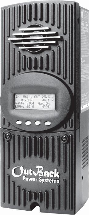
21 5. Status Screen The STATUS Screen displays system information. See page 63 for detailed information of the different Operational Modes. The optional OutBack MATE displays CC (Charge Controller) STATUS screens for convenient distant viewing from the installation location of the Charge Controller. Please see pages to view the Charge Controller screens displayed on the MATE. The PV voltage will slowly rise to the battery voltage level even when the PV breaker is off this is normal as the PV capacitors charge up. PV Input Voltage Battery Voltage Instantaneous Watts AUX status (ON or OFF) In 11.6 V 0.0 A Out 13.8 V 0.0 A kw 0.0 kwh AUX: OFF Sleeping PV Input Current Output current Daily accumulated kilowatt Hours Operational Mode NOTE: Pressing the fi rst soft key opens the MAIN Menu screen. Pressing second soft key opens the End of the Day summary menu/logging. 20
22 6. End of Day Summary Screen The End of Day summary screen appears after one hour of continuous sleeping. This screen can be opened anytime by pressing the second soft key while in the STATUS screen, providing a summary up to that point. Peak output current Accumulated amp hours Day (up to 128 days) Peak Input Voltage Maximum batt voltage obtained Minimum batt voltage obtained Today 0000AH 00.0 kwh 011Vp 00.0Ap 0.00kWp MAX 14.7 V ABS 01:00 MIN 14.6 V FLT 00:00 Accumulated KWh total power production Peak kilowatt hours Accumulated absorb time Accumulated fl oat time NOTE: Pressing the fi rst soft key opens the STATUS screen. Pressing the second soft key brings up the CLEAR LOG screen. Pressing the third soft key shows the previous day s summary; continually pressing this soft key will bring up additional past summaries up to 128 days. Pressing the fourth soft key will bring up summary for the 128th day back. 7. Recharging Using the PV Array In V 0.0 A Out 12.5 V 0.0 A kw 0.0 kwh AUX: OFF Sleeping Turn the PV input breaker on. The Charge Controller automatically detects the PV input voltage. (NOTE: If PV voltage registers 000V when the breaker is on, please check the polarity of the PV wires.) The Charge Controller enters a Wakeup stage, transitions to Tracking and prepares to charge the batteries by tracking the maximum power point of the solar array. In 87.6 V 5.0 A Out 12.5 V 32.9 A kw 0.0 kwh AUX OFF MPPT Bulk During the Charge Controller s initial tracking, the input source (e.g., solar) is gradually loaded from the open circuit voltage (VOC) to one-half of the VOC. Within this range, the Charge Controller seeks the maximum power point. When the Charge Controller goes into Re-Cal, Auto Restart, Wakeup, or RSTRT (restart) modes, among other conditions, it performs an initial tracking. 21
23 8. Accessing the MAIN Menu The MAIN Menu allows the user to adjust and calibrate the Charge Controller for maximum performance. From the STATUS screen, press the fi rst soft key on the left to open the MAIN Menu screen. Charger Aux Light EQ Misc Advanced Logging Stats EXIT GO Press the <GO> soft key after aligning the arrow in front of the selected menu choice. Pressing the <EXIT> soft key in the MAIN Menu returns to the STATUS screen. Press or to move the " to the left of the desired screen. The arrow allows access to any screen to its right. From the MAIN Menu, a user can choose among the following Charge Controller functions by aligning the arrow: Charger CHARGER SETUP - Adjusts the Current Limit, Absorb, and Float recharging voltage set points Aux AUX OUTPUT CONTROL - Secondary control circuit for a vent fan, error alarm, and other system-related additions Light BACKLIGHT CONTROL - Adjusts the backlighting of LCD screen and soft key buttons EQ BATTERY EQUALIZE - Activates battery equalization recharging (manually or automatically) Misc MISCELLANEOUS - Additional settings and service information Advanced ADVANCE MENU - Optimizing/fi ne-tuning the Charge Controller (these are advanced Menus that should be left alone until the user has a good working knowledge of the Charge Controller and its operations) Logging DATA LOGGING - Displays recorded power production information STATS Statistics - Displays recorded peak system information and cumulative kilowatt hours and amp hours 22
24 7. Charger Set-Up This screen allows changes to the Charge Controller s recharging voltage set points Current Limit, Absorb and Float (for an explanation of battery charging, see pages 83-84): The presently selected numerical value will have an arrow Pressing < > selects the value to be changed. You may need to re-enter the password to change these settings. to the left of it. The default charger output current limit setting is 80 amps for the FM80 and 60 amps for the FM60. This setting is adjustable from 5-80 amps. An appropriate breaker must be used between the battery and the Charge Controller. Change Absorbing and Float set points using this screen if the battery manufacturer s recommendations are different than the default values. Otherwise, see page 8 for suggested recharging voltage set points. Charger Aux Light EQ Misc Advanced Logging Stats EXIT GO From the MAIN screen, press or < > to move the " to the left of the Charger function and then press the <GO> soft key. This will open the Charger Set-Up screen. Current Limit 80.0A Absorbing 14.4V Float 13.8V EXIT - + NOTE: If a battery remote temperature sensor (RTS) is used, set the ABSORB and FLOAT setting voltage based on a 25 C / 77 F setting. These are typically the manufacturer s set points (always consult the battery manufacturer s recommendations). RTS compensated voltage values can be viewed in the Advanced menu screen under the RTS Compensation heading. If an RTS is not in use, please see the Non-Battery Temperature Compensated System values (page 85) and adjust the ABSORB/ FLOAT values accordingly. 23
25 8. AUX Mode and Its Functions The AUX is a secondary control circuit essentially, a small power supply that provides a 12VDC (up to 200 milliamps) output current. It is either active (12VDC on) or inactive (0VDC). Most AUX modes or functions are designed for specialized applications and are infrequently used. To access the from the MAIN Menu, press the < the Aux selection (see next page). > soft key until the arrow is in front of A 200 milliamps or less, 12VDC/2.4W device can be wired directly to the AUX terminal; higher output DC loads require a 12VDC coil relay also rated up to 200 milliamps or less for the DC coil which itself is connected to the AUX output. An internal, re-settable Positive Temperature Co-efficient (PTC) fuse protects the AUX internal components from overcurrent or a short circuit. For certain AUX control applications the use of a solid state relay is preferred. This is particularly benefi cial with applications such as the Diversion mode where fast switching (often called PWM control) allows a more constant battery voltage to be maintained. Both DC and AC load switching solid state relays are widely available from many sources. Eurotherm and Power-IO are two suggested solid state relay manufacturers. Only one can operate at a time (even if other modes have been preset). See Figure 5, page 36, for an AUX set-up wiring diagram example. In this Menu, On and Off indicators show the present state of the Aux terminals. Pressing the <MODE> soft key changes the outputs value (On, Off, or Auto) On indicates the Aux Output is in an active state; Off indicates an inactive state. Night Light Output: Off Charger ux Light EQ Misc Advance Logging Stats EXIT GO Off EXIT NEXT SET MODE Pressing the <NEXT> soft key changes to the next mode. This arrow indicates AUX Polarity applies to this function allowing the user to reverse the conditions that activate this function. The second line indicates the present mode for the Aux Output. When this line blinks, it indicates a pending AUX Mode. When the preferred mode is displayed, press the <SET> soft key to select it. TERMS : what is displayed on the Menu Aux Output: 12VDC is either available or unavailable at the Aux Terminal Aux Terminal: the jack to which a relay is wired 24
26 Menu Path Charger Aux Light EQ Misc Advance Logging Stats EXIT GO Charger Aux Light EQ Misc Advance Logging Stats EXIT GO Vent Fan Output: Off Off EXIT NEXT SET MODE PASSWORD ***150*** ENTER - + Vent Fan Output: Off Off EXIT NEXT SET MODE To access the AUX Output Menu: Press the fi rst soft key once from the STATUS Menu to open the MAIN Menu. Press either of the arrow soft keys until the is to the left of Aux. Press the <GO> soft key. If more than ten minutes have passed since any activity, the PASSWORD screen becomes active, requiring the user to input the 141 PASSWORD and press < ENTER>. Pressing the <NEXT> soft key scrolls through the AUX functions. The most commonly used AUX modes are Vent Fan, Low Battery Disconnect and Diversion. Vent Fan Output: Off Off EXIT NEXT SET MODE PV Trigger Output: Off Off EXIT NEXT SET MODE ERROR OUTPUT Output: Off Off EXIT NEXT SET MODE Night Light Output: Off Off EXIT NEXT SET MODE Float Output: Off Off EXIT NEXT SET MODE Diversion: Relay Output: Off Off EXIT NEXT SET MODE Diversion: Solid St Output: Off Off EXIT NEXT SET MODE Low Batt Disconnect Output: Off Off EXIT NEXT SET MODE Remote Output: Off Off EXIT NEXT SET MODE 25
27 AUX modes in order of appearance on the Charge Controller display: Vent Fan PV Trigger Error Output Night Light Float Diversion Relay Diversion Solid State Low Battery Disconnect Remote NOTE: All AUX functions can be manually activated in On, Off, or Auto mode. In Auto mode, the function will automatically activate when a user-determined value is met and deactivate or shut down when other conditions described here, such as a certain amount of time passing, occur. When an is in AUTO, 12VDC is available at the AUX terminals and a condition, such as a voltage set point, is met. Other modes can be programmed in lieu of the specifi c ones listed here, but the Vent Fan mode is most easily changed (e.g., to activate an alarm instead of a fan). Here are the default AUX modes: Vent Fan when the Vent Fan voltage set point is exceeded, the vent fan will run for at least 15 seconds (the fan helps remove hydrogen from battery enclosure), even if the set point is exceeded for only a few seconds due to a surge. If the set point is exceeded for longer than 15 seconds, the fan will stay on until the voltage drops below the set point. It then takes 15 seconds before the fan shuts off. This is an optional external fan and not to be confused with the Charge Controller s internal, thermally activated fan which cools the unit. PV Trigger* activates an alarm or relay (that disconnects the array); when the PV input exceeds the user-determined voltage set point (to avoid damage, do not go over 150VDC), the PV Trigger disconnects after a minimal adjustable amount of Hold Time. Error Output useful for monitoring remote sites, switches to the Off state if the Charge Controller has not charged the batteries for 26 hours or more (not an audible alarm, only displayed as a printed message on Charge Controller AUX Menu) or the battery voltage has fallen below a user-determined set point for 10 continuous minutes. In the No Error state, the AUX output is on. Night Light* after the PV voltage is below a threshold voltage for a user-determined time period, a user-provided light illuminates as long as the Charge Controller remains sleeping or as determined by the user-established time limit. Float powers a load if the Charge Controller is producing power in the Float stage Diversion Relay* diverts excess power away from batteries when a wind or hydro generator is connected directly to the batteries. Diversion Solid St same as Diversion Relay, but applies when a solid state relay is used rather than a mechanical relay Low Batt Disconnect activates/deactivates the AUX load(s) when a user-determined voltage and time levels are reached. Remote allows OutBack MATE control of the (see MATE manual for details). * These functions support AUX polarity. 26
28 9. Programming the S VENT FAN Output: Off EXIT NEXT Vent Fan Off SET MODE On Off Auto Press the <MODE> soft key to manually activate or deactivate (On or Off) the Vent Fan; if set to Auto, the Vent Fan will turn on when a user-determined voltage is met. Press the <SET> soft key to view the Vent Fan screen. To view other screens, continue to press the <NEXT> soft key. EXIT Vent Fan VOLT The Vent Fan helps remove hydrogen from the battery box. The ventilation fan referred to here is not the same as the Charge Controller cooling fan. Press the <VOLT> soft key to determine the battery voltage that will activate the and start the fan. VENT FAN VOLTS > 14.4 Adjust the voltage level using the < - > and < + > soft keys. Press the <BACK> soft key to return to the Vent Fan screen. BACK
29 Vent Fan Press the <EXIT> soft key return to the main Vent Fan screen. EXIT VOLT Vent Fan Output: Off Off Press the <NEXT> sot key to view the PV Trigger screen EXIT NEXT SET MODE PV TRIGGER PV Trigger Output: Off EXIT Off NEXT SET MODE On Off Auto When the PV input exceeds the user-determined VOLT set point, the PV Trigger activates in Auto Mode. Press the <MODE> soft key to establish another PV Trigger mode (On, Off, or Auto). 28
30 PV Trigger Output: On EXIT On NEXT SET MODE Press the <SET> soft key to open the PV Trigger s TIME and VOLT(age) set menus. PV Trigger To adjust the voltage, press the <VOLT> soft key. EXIT TIME VOLT PV VOLTS >140 BACK - + Adjust the voltage within a range of 20V-145V by pressing the < - > or < + > soft key. When fi nished, press the <BACK> soft key to return to the PV Trigger screen EXIT PV Trigger TIME VOLT To adjust the minimum amount of time the PV voltage must remain high before deactivating the, press the <TIME> soft key. 29
31 Hold Time Sec 01.1 BACK - + Press the < - > or < + > soft key to adjust the Hold Time, then press the <BACK> soft key to return to the PV Trigger screen. In this example, the will remain active for 1.1 seconds after the PV voltage is below the PV Trigger voltage before deactivating the PV Trigger and reconnecting to the array. PV Trigger Press the <EXIT> soft key to return to the initial PV Trigger screen EXIT TIME VOLT PV Trigger Output: On EXIT On NEXT SET MODE Press the <NEXT> soft key to view the ERROR OUTPUT screen. 30
32 ERROR OUTPUT ERROR OUTPUT Output: On On EXIT NEXT EXIT SET MODE ERROR OUTPUT 01 hrs VOLT On Off Auto The ERROR OUTPUT default state is On, meaning 12 VDC is present at the AUX terminal. If the Charge Controller has not charged the batteries for 26 hours or more continuously, the inaudible ERROR OUTPUT goes into an Off state. The ERROR OUTPUT is intended for remote locations to signal (e.g., a telecommunication signal to a computer) when the Charge Controller has not charged the battery for 26 hours or more. Press the <SET> soft key to advance to the ERROR OUTPUT volt screen. The ERROR OUTPUT screen displays the number of hours the Charge Controller has not been producing any power (the number of hours in Sleep Mode). Press the <VOLT> soft key to adjust the ERROR LOW BATT VOLTS screen. ERROR LOW BATT VOLTS <11.5 BACK - + EXIT ERROR OUTPUT 01 hrs VOLT User-determined value not less than 10V will trigger an alarm or, through a user-supplied modem, send a signal from a remote installation indicating the battery charge has reached this value. This informs the user of a low battery problem. Use the < - > and < + > soft keys to change this value. Press the <BACK> soft key to return to the ERROR OUTPUT screen. Press the <EXIT> soft key to bring up the original ERROR OUTPUT screen. ERROR OUTPUT Output: On On Press the <NEXT> soft key to view the Night Light screen. EXIT NEXT SET MODE 31
33 NIGHT LIGHT Night Light Output: Off Off EXIT NEXT SET MODE On Off Auto The Night Light illuminates a user provided low-wattage light when the PV voltage falls below a user-determined voltage. Off is the default value. Press the <MODE> soft key to change the Night Light MODE (Off, On, or Auto). Night Light Output: Off Auto EXIT NEXT SET MODE This example shows Auto MODE selected. Press the <SET> soft key to open the Hysteresis and PV Voltage screens. Night Light Press the <HYST> soft key to open the On Hysteresis Time screen. EXIT HYST TIME VOLT Night Light On Hysteresis Time Minutes 000 BACK - + OFF Use the < - > and < + > soft keys to adjust the time required for the PV input voltage to be below the threshold voltage before the Night Light is enabled. Press the <OFF> soft key to view the Off Hysteresis Time screen. 32
34 Night Light Off Hysteresis Time Minutes 000 BACK - + Use the < - > and < + > soft keys to adjust the time required for the PV input voltage to be above the threshold voltage before the Night Light is disabled. Press the <BACK> soft key twice to return to the Night Light screen. EXIT Night Light HYST TIME VOLT Press the <TIME> soft key to adjust the length of time the Night Light remains on. If the time is set to 0, the Night Light remains on until the off condition is met. Night Light On Time Hours 23 BACK - + Use the < - > and < + > soft keys to adjust the number of hours the Night Light remains on. Press the <BACK> soft key to return to the previous Night Light screen. EXIT Night Light HYST TIME VOLT Press the <VOLT> soft key. Night Light Threshold Voltage 010 BACK - + Press the < - > or < + > soft keys to adjust the Threshold Voltage value. When fi nished, press the <BACK> soft key to return to the Night Light screen. 33
35 EXIT Night Light HYST TIME VOLT Press the <EXIT> soft key to return to the Night Light AUX mode. Night Light Output: Off Auto Press the <NEXT> soft key ro view the AUX Float screen. EXIT NEXT SET MODE FLOAT Float Output: Off Off EXIT NEXT SET MODE On Off Auto The is active when the Charge Controller is in Float and producing power. Press the <NEXT> soft key to advance to the Diversion screen. RELAY Diversion: Relay Output: Off EXIT NEXT Off SET MODE On Off Auto When external DC sources (wind, hydro) are directly connected to a battery bank, any excess power should be sent to a diversion load, such as a heating element, via a mechanical or solid state relay. In Diversion, which features Relay and Solid State screens, the user programs set points from -5.0 volts to 5.0 volts relative to the Absorb, Float and EQ voltages to activate the. With wind or hydro generator applications, keep the Charge Controller s diversion voltage slightly above its Absorb and Float voltages for efficient functioning. This is primarily an off-grid function. Pressing the <MODE> soft key displays Auto and On modes in addition to Off. Pressing the <SET> soft key displays the Diversion: Relay TIME and VOLT screen. 34
36 Diversion: Relay EXIT TIME VOLT Press the <TIME> soft key to advance to the Time screen which allows the user to adjust the minimum time the is active after the battery voltage falls below the Hysteresis voltage. Hold Delay 01.0 Time 00 seconds BACK - + DLY+ Diversion: Relay Hold Time shows how long the stays active after the battery voltage has fallen below the HYST (Hysteresis) set point. The user can adjust the Hold Time from 0.1 to 25 seconds. The Delay Time shows how long the battery voltage must be above the Relative Volts before the is activated. It can be adjusted from 0 to 24 seconds, but is rarely required. Pressing the <BACK> soft key returns to the Diversion: Relay TIME and VOLT screen. Press the <VOLT> soft key. EXIT TIME VOLT Absorb--Float--EQ Relative Volts BACK - + HYST Use this screen to establish the set points for starting and ending the relative to the Absorb, Float, and EQ voltages. The < - > and < + > soft keys set the Diversion set points. The <HYST> (Hysteresis) set point establishes when the becomes inactive after the battery voltage falls below the Relative Volts voltage minus the HYST value. After establishing these values, press the <BACK> soft key to return to the Diversion: Relay TIME and VOLT screen. 35
37 Diversion: Relay Press the <EXIT> soft key. EXIT TIME VOLT Diversion: Relay Output: Off On EXIT NEXT SET MODE If a Solid State Relay is used, press the <NEXT> soft key to access the Diversion Solid St screen. Diversion: Solid St Output: On EXIT On NEXT SET MODE To adjust the time and voltage when a solid state relay is used, press the <TIME> and <VOLT> soft keys respectively and follow the same steps as for the Diversion:Relay screen. Note the values are displayed as percentages when a solid state relay is used. When any adjustments are completed, return to the Diversion: Solid St screen and press the <NEXT> soft key to view the Low Batt Disconnect screen. Example of Diversion Diversion Off EXIT NEXT TIME VOLT Absorb Float EQ Relative Volts BACK - + HYST + Hold Delay 15.0 Time 10 Seconds BACK - + DLY + Each recharging state Absorb, Float, or EQ has a recharging voltage set point. The Diversion AUX MODE can be active (On) when the battery voltage is raised above one of these set points for a certain amount of time or inactive (Off) when it falls below. The user can determine these voltages and times. In the example above, when the RE source (wind or hydro) raises the battery voltage 00.2v above the chosen set point for a Delay time of 10 seconds the AUX Output will be active. When the battery voltage falls 00.3v below the HYST voltage set point for a Hold time of 15 sec the AUX Output will be inactive (Off). See Figure 5, next page, for Diversion Load and AUX Wiring Set-Up. 36
38 37 Figure 5 Diversion Load and AUX Wiring Set-Up Illustrated
39 LOW BATTERY DISCONNECT Low Batt Disconnect Output: On On EXIT NEXT SET MODE On Off Auto When the battery voltage falls below the disconnect volts, the AUX connected loads only are disconnected; the AUX connected loads only are connected when the battery voltage rises above the reconnect volts. To adjust these set points, press the <TIME> and <VOLT> soft keys. Low Batt Disconnect Press the <TIME> and <VOLT> soft keys to adjust the set points. EXIT TIME VOLT Delay Time Sec 01 Timer 001 BACK - + Press either the < - > or < + > soft key to adjust the delay time. This is the time period the Charge Controller waits before either activating or deactivating the when either the disconnect or reconnect voltages are reached. When the low voltage occurs, the timer shows the seconds remaining before disconnecting. When the reconnect voltage is reached, the timer shows the user-determined time before connecting. Press the <BACK> soft key to return to the Low Batt Disconnect screen. 38
40 EXIT Low Batt Disconnect TIME VOLT In the Low Batt Disconnect screen, press the <VOLT> soft key to adjust the battery voltage disconnects set point. DISCONNECT VOLTS < 13.6 BACK - + ReCon Press either the < - > or the < + > soft key to adjust the disconnect voltage. Press the <ReCon> soft key to open the RE-CONNECT VOLTS screen. RE-CONNECT VOLTS > 14.4 BACK - + DisV Press either the < - > or the < + > soft key to adjust the RE-CONNECT VOLTS value. The AUX Output activates when the voltage goes above this setting after the timer has counted back to zero. Press the <BACK> soft key to return to the Low Batt Disconnect screen. Press the <DisV> soft key to return to the Disconnect Volts screen. 39
41 Low Batt Disconnect Press the <EXIT> soft key. EXIT TIME VOLT Low Batt Disconnect Output: Off On Press the <NEXT> soft key to view the Remote screen. EXIT NEXT SET MODE REMOTE Remote Output: Off EXIT NEXT On SET MODE On Off Auto In Remote, the OutBack MATE can control the Charge Controller s. Press the <EXIT> soft key twice to return to the MAIN Menu screen. Charger Aux Light Eq Misc Advanced Logging Stats Press the < > soft key to move the to the Light option. When the is in front of Light, press the <GO> soft key. EXIT GO 40
42 10. Backlight BACKLIGHT CONTROL Auto Time 2 Minutes Auto EXIT - + MODE On Off Auto Auto (default) leaves backlight and soft keys on for up to nine minutes whenever any soft key is pressed (pressing any soft key when the LCD is not lighted does not change any settings). Minutes are adjustable using the < -> and < + > soft keys. On or Off states are also available. Charger Aux Light EQ Misc Optimize Logging Stats EXIT GO Press the <EXIT> soft key twice to return to the MAIN Menu screen Press the < > soft key to move the to the EQ option. When the is to the left of EQ, press the <GO> soft key. 11. EQ Battery Equalize The intent of an equalization charge is to bring all battery cells to an equal voltage. Sealed batteries should not be equalized unless specifi cally instructed by the manufacturer. Shut off or minimize all loads on the battery. When equalizing, be sure the EQ voltage will not damage any still energized DC load. If possible, ensure the EQ cycle starts and stops the same day it is initiated or unnecessary battery gassing will occur. Occasional equalization extends the life of fl ooded electrolyte batteries. Proceed with caution! A vent fan is recommended in enclosed spaces. The Charge Controller allows the user to set voltages and times of equalization process. Both manual and auto modes are available. EQ voltage is not battery temperature compensated. Always check the electrolyte level in the batteries before and after equalizing. 41
43 BATTERY EQUALIZE Volts 15.0 EXIT NEXT -EQV +EQV Press either the < EQV> or <+EQV > soft key to change the EQ voltage, following your battery manufacturer s recommendations. Note that the factory default EQ voltage is set low, the same as the factory default Absorb voltage. Press the <NEXT> soft key to view the BATTERY EQUALIZE Time screen. BATTERY EQUALIZE Time 01 Hours EXIT NEXT -HRS +HRS Press either the <-HRS> or <+HRS> soft key to set the desired equalization time, up to a seven hour maximum, always following your battery manufacturer s recommendations. Press the <NEXT> soft key to view the battery equalization start screen. Manual Mode (default mode) BATTERY EQUALIZE 1 Hours 15.0 Volts Check water level BACK AUTO START STOP Press the <START> soft key to manually begin an equalization cycle. To stop the cycle, press the <STOP> soft key. EQ-MPPT display indicates the Charge Controller is trying to reach the target equalize set point. Equalize time EQ 0:00 in Hours:Minutes displays after the equalize set point is reached. The incomplete equalization cycle continues into the next day unless the Charge Controller is powered off or manually stopped. The remaining EQ time can be viewed in the Stats menu. EQ cycle terminates when EQ time period is reached. After equalizing, an EQ DONE message displayed and a Float cycle begins. This message remains displayed until a soft key is pressed. Press the <AUTO> soft key to view the auto equalization screen. 42
44 AUTO MODE COUNT EQ INTERVAL EXIT -DAY +DAY Use the <-DAY> and <+DAY> soft keys to preset the interval day to initiate an automatic equalization cycle. The EQ INTERVAL displays the number of days in the interval between cycles and COUNT displays how many days of the interval have passed. To view the MAIN EQ screens, press the <EXIT> soft key. NOTE: Auto Mode initiates when a preset interval day (1-250 days) is reached. The default equalize interval (EQ INTERVAL) setting is 000 day leaving the auto eq disabled. EQ-MPPT display indicates the Charge Controller is trying to reach the target equalize set point. The equalize time EQ 0:00 in Hours:Minutes displays after the equalize set point is reached. An incomplete equalization cycle continues into the next day unless the Charge Controller is powered off or manually stopped. The remaining EQ time can be viewed in the Stats Menu. The COUNT value will be cleared to 000 when an EQ is started, manually stopped, or Charge Controller has been powered off. After recharging, an EQ DONE message displays and a Float cycle begins. EQ DONE is displayed until (1) any soft key is pressed or (2) a new day occurs for systems using an OutBack MATE. BATTERY EQUALIZE Volts 15.0 Press the fi rst soft key twice to return to the MAIN Menu. EXIT NEXT -EQV +EQV Charger Aux Light Eq Misc Advanced Logging Stats Press the < > soft key until the is in front of Misc. Press the <GO> soft key to view the Misc screen. EXIT GO 43
45 12. MISC Miscellaneous The MISCELLANEOUS screens display extra settings and technical information, some of which is useful for OutBack Power Systems Technical Services. The Grid Tie (GT) value is sent from G-series inverter through the MATE and HUB for Grid Tie control communications. GT means The Charge Controller is in grid tie mode and communicating with the GT Series Inverter. Each MPPT operation is a state. This number is useful for OutBack troubleshooting. GT State PWM% ChgT This is the duty cycle of the converter. At 50%, the PV terminals would be twice the battery voltage. The Bulk/Absorb charge timer counts up to the Absorb time limit. EXIT NEXT RSTRT Press NEXT to Continue to the Force Bulk/Float Screen. RSTRT forces the Charge Controller to restart or wake-up from 5-minute (default) long Snoozing mode. Restart and wakeup are mainly service features. 44
46 GT State PWM% ChgT EXIT NEXT RSTRT Press the <NEXT> soft key to view the FORCE FLOAT, or BULK screen. FORCE EXIT NEXT FLOAT BULK Pressing the <FLOAT> or <BULK> soft key forces the Charge Controller to that specifi c recharging cycle and returns to the STATUS screen. Forcing a FLOAT or BULK recharge will end an EQ cycle. Press the <NEXT> soft key to view the third MISCELLANEOUS screen. Force FLOAT = fl oat cycle Force BULK = bulk cycle This is the assigned number representing the temperature of the internal components to control the cooling fan. The lower the number, the higher the temperature. 25 C is approximately a value of 525. Btmp is a battery temperature sensor reference value used to compensate the charging voltage. This is an arbitrary number between 0 and 255 and is not the actual temperature. An X next to this value indicates a Global external RTS is being used (system with a HUB and MATE). The target voltage the controller is trying to reach. PCB Target Btmp CFB v EXIT BACK The output value of the internal current sensor is used to calculate output amps, watts, and track the Maximum Power Point of the array. Press the <EXIT> soft key twice to return to the MAIN MENU. 45
47 13. Advanced The ADVANCED MENU allows fi ne-tuning of the Charge Controller operations including Snooze periods and Maximum Power Point limits. In order of appearance, the following modes occur in the ADVANCED Menu selections: Snooze Mode Wakeup MPPT Mode Park Mpp Mpp Range Limit % Voc Absorb Time Rebulk Voltage Vbatt Calibration RTS Compensation Auto Restart Aux Polarity Reset to Defaults? From the MAIN Menu, choose Advanced and press the <GO> soft key. ADVANCED MENU Snooze Mode <.6 amp EXIT NEXT AMP Snoozing occurs if the recharging current does not reach the user-selected cutoff current set point as shown in this screen. Press the <AMP> soft key to adjust the amp setting. Press the <NEXT> soft key for the Wakeup Mode screen. Amp Values
48 ADVANCED MENU Wakeup Mode 1.5V 05m EXIT NEXT +VOC +Min Wakeup Mode selects how often the Charge Controller does a Wakeup during Snoozing periods. Since environmental conditions impact the open circuit voltage (Voc) of an array, a user selectable Voc rise in value will allow the controller to wakeup sooner or later based on the last measured Voc value. A selectable delay time in minutes will also allow the controller to Wakeup sooner or later if the measured Voc did not meet the user selectable Voc rise in value. Before changing these values, monitor your system for a week or so using the factory defaults and then gradually adjust the set points. If they re set too high, the Charge Controller might not wake up soon or often enough, which means a loss of power production. Note: +VOC ranges from 1.5V up to 9.5V. +MIN ranges from 5 up to 15 minutes. Press the <NEXT> soft key to go to the MPPT Mode screen. U-Pick %Voc and Auto Track are the two modes appearing on this screen. ADVANCED MENU MPPT Mode Auto Track EXIT NEXT nongt MODE This screen allows the user to choose one of these modes: Auto Track MPPT Mode (the default and preferred mode) automatically tracks the PV upon wakeup and then tracks the MPP of the array. If the Auto Restart is set to 1 or 2, the Charge Controller awakes every 1.5 hours and does an initial tracking. U-Pick % (Voc) MPPT mode operates the PV voltage at a user-selected percentage of the Voc. This percentage is displayed in the Park Mpp % Voc screen along with the current output wattage. The wattage value changes as the user adjusts the Voc percentage, allowing the user to lock-in the most advantageous percentage value. U-Pick % acquires a new VOC value every 1.5 hours if Auto Restart is set to 1 or 2. Press the <MODE> soft key to choose an MPPT mode. If you have an OutBack G-series inverter system with a HUB and MATE, press the <nongt> soft key to activate the charge controller s grid-tie mode. Press the <NEXT> soft key to view the Park Mpp screen. 47
49 ADVANCED MENU Park Mpp 77 % Voc EXIT NEXT -% +% ADVANCED MENU Park Mpp Watts % Voc EXIT NEXT -% +% As the user changes the %Voc value using the <-%> and <+%> soft keys, the displayed Watts value also changes. Watts appears when U-Pick is selected. Press the <NEXT> soft key to view the Park Mpp screen. ADVANCED MENU Mpp Range Limit %Voc Min Max EXIT NEXT 1/2 90% Use ½ value for high input arrays to speed up initial tracking. U-Pick % (Voc) MPPT mode operates the PV voltage at a user-selected percentage of the VOC which is displayed in the Park Mpp % Voc screen. Press the <NEXT> soft key to view the Mpp Range Limit % screen. The Mpp Range Limit % Voc adjusts the upper Mpp limit of the VOC. The default Charge Controller MPP voltage limit is set at 90% of the VOC and is normally left alone for an array. Setting min to 1/2 reduces the initial tracking time on a high input voltage array and also tracks one-half the VOC voltage. The MPP adjustable Charge Controller limits are 80%, 85%, 90%, and 99% of the VOC. The min range limit setting may be set to FULL if something other than a PV array is connected to the input of the Charge Controller, such as a micro-hydro generator (see page 58), but the VOC cannot exceed 150 VDC at any time. Press the <min> or <max> soft key to adjust the MPP range limit. When done, press the <NEXT> soft key to view the Absorb Time screen. 48
50 14. Charging-Related Screens ADVANCED MENU Absorb Time Limits 01.0 hours EXIT NEXT - + In the Absorb Time Limits screen, the user can set the duration the Charge Controller stays in the Absorb recharge cycle. Absorb Time is adjustable from 0 to 24 hours (consult your battery manufacturer s recommendations). A Bulk cycle starts each morning (see chart next page). The charge timer (ChgT) is preset to zero. The ChgT counts up to the Absorb Time Limit after the Absorb voltage is reached. If the system cannot maintain the Absorb voltage set point during the Absorb cycle, the timer will stop counting up. If the battery voltage is greater than or equal to 12.4V, 24.8V, 37.2V, 49.6V 62.0V and less than the absorb voltage, the ChgT timer does not change. If the battery voltage is less than 12.4 V, 24.8V, 37.2V, 49.6V or 62.0V, the ChgT timer counts down to zero in minutes for every minute elapsed, one minute is subtracted from the timer. If the battery voltage is less than 12.0V, 24.0V, 36.0V, 48.0V or 60.0V, the ChgT timer counts down to zero at twice as fast for every minute elapsed, two minutes is subtracted from the timer. If the battery voltage is less than 11.6V, 23.2V, 34.8V, 46.6V, or 58.0V, the ChgT timer counts to zero four times as fast for every minute elapsed, four minutes is subtracted from the timer. When the Absorb Time Limit is reached, the Charge Controller goes into Float stage and may briefl y display Charged then Float. When the battery voltage drops below the fl oat voltage set point, the Charge Controller recharges to maintain this set point, employing the F(Float)-MPPT function. To adjust the Absorb Time limit, press either the < + > or < -> soft key. When fi nished, press the <NEXT> soft key to view the next screen. 49
51 Charge Controller Multi-Stage Battery Charging Figure 6 NOTE: In BULK, the Charge Controller will charge as long as necessary to complete the cycle, regardless of the timer s set points ADVANCED MENU Absorb End Amps 00 A EXIT NEXT - + An Absorb charge cycle normally ends when a battery voltage is maintained at the Absorb set point for the user-determined time period. Use the < -> or < + > soft keys to adjust the Absorb End Amps to an optimal value (the default value is 00). While the battery voltage is at or above the Absorb target and the Absorb End Amps value is reached for a time delay of 15 seconds, the Charge Controller will switch to the Float stage regardless of the charger time minutes as shown in the Misc menu under ChgT. The charger timer will be cleared. This is an optional set point and is used for few installations. When fi nished with any adjustments, press the <NEXT> soft key to view the Rebulk Voltage screen. ADVANCED MENU Rebulk Voltage 12.6 V EXIT NEXT - + In Float, if the battery voltage falls below the ReBulk Voltage set point for at least 90 seconds, the Charge Controller will automatically reinitiate a Bulk charge cycle. The default is set to 6 volts, a very low value that will disable this function. The Rebulk Voltage value can be adjusted by pressing the < - > or < + > soft keys. Press the <NEXT> soft key to view the Vbatt Calibration screen. 50
52 ADVANCED MENU Vbatt Calibration 14.1 V 0.0 V EXIT NEXT - + RTS Compensation* ADVANCED MENU RTS Compensation A 14.1 V F 13.8V EXIT NEXT WIDE ADVANCED MENU RTS Compensation A 14.1 V F 13.8 V EXIT NEXT LIMIT SET A quality calibrated voltmeter will provide even more accurate Charge Controller battery readings if an undesirable voltage drop occurs. When measuring battery voltage, ensure a good connection is made to the four wire lugs. Check the battery temperature compensation voltages if the voltages are much different than you expect from the charger setup Absorb and Float voltage settings. Use the <-> and <+> soft keys to match the readings from the voltmeter (use of appropriate wire gauge will minimize voltage drop). When fi nished, press the <NEXT> soft key to view the RTS Compensation screen. During cold weather, a battery often requires a higher recharging voltage. Lower quality inverters might not accommodate these higher voltages and can shut down during recharging, cutting off power to their loads. The Charge Controller allows the user to lower the compensated voltage in the Absorb cycle so these inverters will remain operating. Also, some batteries have an absolute voltage limit that should not be exceeded and the WIDE/LMIT option allows the user to control this during recharging. WIDE allows the RTS full control over recharging; LIMIT sets the ceiling and fl oor voltages for the RTS. During hot weather, the LIMIT feature set point assures recharging will continue at a high enough voltage rather than dropping too low in reaction to a higher ambient temperature. This assures the recharging voltage adequately charges, but should be monitored according to the battery manufacturer s recommendations. The RTS default compensated voltages apply if the WIDE/ LIMIT option is set to WIDE. To change these values, press the <WIDE> soft key to bring up the next screen which allows user-determined limits. Press the <SET> soft key to adjust these values. RTS COMPENSATION Upper LIMIT 14.1 V Lower LIMIT 13.2 V BACK - + Press the < > soft key to choose the limit value you want to adjust. Press the < - > and < + > soft keys to adjust the chosen value(s). When fi nished, press the <BACK> soft key to return to the RTS Compensation screen. *Optional OutBack RTS must be installed 51
53 ADVANCED MENU RTS Compensation A 14.4 V F 13.8V Press the <NEXT> soft key to view the Auto Restart screen. EXIT NEXT LIMIT SET AUTO RESTART ADVANCED MENU Auto ReStart MODE 2 EXIT NEXT MODE Pressing the fourth soft key selects among the three Charge Controller Auto ReStart modes: 0 (default), 1, and 2. Auto ReStart allows the Charge Controller to perform internal recalibrations. ADVANCED MENU Auto ReStart MODE 0 EXIT NEXT MODE ADVANCED MENU Auto ReStart MODE 1 EXIT NEXT MODE Mode 0 Auto ReStart mode is disabled; the Charge Controller recharges continuously from an available source and never Restarts. Mode 0 would be chosen to avoid spinning a microhydro generator every 1.5 hours. Mode 1 once every 1.5 hours, when the Charge Controller is in Bulk, it will briefl y Restart and initiate a full panel tracking. This will not reset any counters or charging stages or statistics. Mode 2 Auto ReStart every 1.5 hours; in Bulk, Absorb, and Float modes, it will briefl y Restart and initiate a full panel tracking. This will not reset any counters or charging stages or statistics. 52
54 ADVANCED MENU Auto ReStart MODE 2 From the Auto Restart MODE 2 screen, press the <NEXT> soft key to view the Aux Polarity screen. EXIT NEXT MODE ADVANCED MENU Aux Polarity Active High EXIT NEXT MODE When the AUX function is ON, 12 volts is present at the AUX terminal; when it s OFF, 0 volts are present at the terminal. Aux Polarity allows the user to reverse the availability of this voltage for the Night Light, PV Trigger, or Diversion Relay functions. In Active High, the user establishes certain conditions for these functions. Pressing the <MODE> soft key brings up the Active Low screen which allows the user to reverse these conditions. ADVANCED MENU Aux Polarity Active Low EXIT NEXT MODE In the Active Low zero voltage will be available for a function that in Active High would normally have voltage. When one of the three functions Night Light, PV Trigger, or Diversion Relay has been chosen as the AUX function, an arrow in the right hand corner of the screen will refl ect the Aux Polarity state. An arrow pointing up means Active High while an arrow pointing down means Active Low. Press the <NEXT> soft key to view the Reset to Defaults? screen. EXAMPLE PV Trigger Output: Off Off EXIT NEXT SET MODE PV Trigger Active High PV Trigger Output: Off Off EXIT NEXT SET MODE PV Trigger Active Low ADVANCED MENU Reset to Defaults? EXIT NEXT RESET In this screen, a user can press the <RESET> soft key to return the Charge Controller to the factory default settings. (If you do not need to reset, press the <EXIT> soft key to return to the STATUS screen.) 53
55 YES Are you sure? Reset to Defaults NO Pressing the <YES> soft key brings up a Reset to Defaults screen momentarily before returning to the Reset to Defaults? screen ADVANCED MENU Reset to Defaults? Press the <EXIT> key twice to return to the MAIN Menu screen. EXIT NEXT RESET Charger Aux Light Eq Misc Advanced Logging Stats EXIT GO From the MAIN Menu, press the < > soft key to move the arrow next to the Logging function and then press the <GO> soft key. This leads to the End of the Day Summary screen, which is a log of the daily statistics and can be viewed at any time. 54
56 15. Logging Today 0000Ah 00.0 KWH 011Vp 00.0Ap 0.00kWp MAX 14.7V ABS 01:00 MIN 14.6V FLT 00:00 A user can clear either the daily or accumulated statistics of the Charge Controller by pressing the second button from the left in this screen. This will bring up the CLEAR LOG screen. CLEAR LOG BACK TOTL DAILY The CLEAR LOG screen offers the option of clearing up to 128 days of accumulated statistics or the total in the secondary STATS screen (page 56). Press and hold either the <TOTL> (total) or <DAILY >key to clear those specifi c statistics. NO Are you sure? YES The Are you sure? screen appears. Pressing the <YES> soft key returns to the CLEAR LOG screen; pressing the <NO> soft key returns to the Logging screen. Today 0000Ah 00.0 KWH 011Vp 00.0Ap 0.00kWp MAX 14.7V ABS 01:00 MIN 14.6V FLT 00:00 Pressing the third and fourth soft keys changes the displayed day s statistics, by moving either forward or backward within the 128 days of available statistics that are viewable. NOTE: If two or more Charge Controllers are used in the same system and are started up or cleared on different days, their numeric dates will not be the same. This can lead to some misunderstandings when looking back and comparing data between the two or more units. A user looking back at day 12 on both units would fi nd very different results. 55
57 16. Stats Charger Aux Light Eq Misc Advanced Logging Stats EXIT GO From the MAIN Menu, press the < > soft key to move the arrow next to the Stats function and then press the <GO> soft key The STATS screen displays additional voltage and time information. Maximum battery voltage seen by the Charge Controller Max Watt seen by the Charge Controller Daily high VOC value Max Bat Voc MaxVoc MaxWatt 0000 Sunrise EXIT NEXT 01:30:33 The highest Voc seen by the Charge Controller In a stand alone Charge Controller one that is not connected to a MATE Sunrise shows how long ago the Charge Controller woke up for the fi rst time each day and when the daily and total logged values were updated and cleared from the STATUS screen. If the Charge Controller is connected to a MATE, the logging occurs at midinght. Press the <NEXT> soft to view the second STATS screen. 56
58 Secondary STATS screen Total 0000 Total kwh kah The Secondary Stats screen shows the total accumulated DC and AC kilowatt hours and kiloamp hours of the Charge Controller. BACK Total 0000 Total DCkWH kwhac kah Pressing the <DCkWH> soft key switches the screen between DC kilowatt hours and AC kilowatt hours DCkWH shows the DC kilowatthours and should be used in a non-grid-tied system ACkWH is used with a grid-tied system. This measure is based on a 90% inverter efficiency (1 kwh DC= 0.9 kwh AC) BACK ACkWH Pressing the fi rst soft key three times returns to the MAIN Menu screen. 57
59 17. Micro-Hydro and Fuel Cell Applications The Charge Controller is designed to work with solar arrays. Although it will work with micro-hydro turbines and fuel cell, OutBack Power Systems can only offer limited technical support for these applications because there is too much variance in micro-hydro and fuel cell generator specifi cations. When used for micro-hydro or fuel cell applications, the Charge Controller warranty will be honored only if the manufacturer and turbine model have been approved by OutBack Power Systems. Please check with one of the following manufacturers or OutBack Power Systems before employing the Charge Controller with these applications: Harris Hydroelectric (831) Alternative Power & Machine (541) Energy System & Design (506) The Charge Controller is not compatible with wind turbine applications and OutBack cannot warranty its use in these applications. MICRO-HYDRO AND FUEL CELL SYSTEMS PERFORMANCE OPTIMIZATION Micro-hydro and fuel cell systems are different than PV systems, whose VOC output is more subject to change due to weather and time of day. A PV system normally fi nds its Maximum Power Point voltage between 50-90% of its VOC. A micro-hydro or fuel cell system s MPP voltage can be outside of this range. The Charge Controller allows a user to experiment and fi nd more appropriate set points to best capture the MPP voltage using U-Pick mode. Otherwise, Auto Track begins tracking the VOC and works its way down until the optimum percentage of input voltage yields the MPP voltage. If U-Pick % Voc is chosen, the MPP is calculated by whatever value is found in Park Mpp, even if it s not the optimal value for determining the MPP voltage. For this reason, OutBack normally suggests leaving the system in Auto Sweep mode. 58
60 18. Advanced Menu (Micro-Hydro and Fuel Cell Applications) Mpp Range Limit % (Auto Track Mode only) The Charge Controller searches for the MPP voltage by tracking the input voltage up to one half (default) of the Voc, which is based on values appropriate for a solar array. Micro-hydro and fuel cell systems can require a broader range, normally on the lower end. Adjusting the lower limit, expressed as 1/2 on the display screen, for FULL allows the Charge Controller to track the input voltage close to the battery voltage instead of 1/2 (or 50%) of the Voc. This adjustment only affects the initial tracking at the beginning of the day and any subsequent trackings caused by Auto-Restart or any forced restart of the Charge Controller. Charger Aux Light Eq Misc Advanced Logging Stats EXIT GO To adjust the Lower Mpp Range Limit: From the MAIN Menu, with the arrow in front of Advanced, press the <GO> soft key. ADVANCED MENU Mpp Range Limit %Voc Min Max EXIT NEXT 1/2 90% In the ADVANCED MENU screen, press the <NEXT> soft key until the Mpp Range Limit % Voc screen appears. Press the <1/2> soft key until FULL appears. When fi nished, press the <NEXT> soft key until the MPPT Mode screen appears. ADVANCED MENU MPPT Mode Auto Track EXIT NEXT nongt MODE To pick between Auto Track or U-Pick % MPPT Mode and determine the Charge Controller s operating Voc percentage, press the <MODE> soft key to interchange between the two modes. Re-entering the password might be required. After choosing a mode, press the <NEXT> soft key in the ADVANCED MENU to view the Park Mpp screen (only applicable for U-Pick mode). ADVANCED MENU Park Mpp Watts % VOC Press the <-VOC> or <+VOC> soft key to select one of the percentage values; U-Pick always uses the Park Mpp value. EXIT NEXT % +% 59
61 19. Abbreviated Menu Map Much of the Charge Controller activity takes place around the MAIN screen. From this screen, the user can access other screens to both observe system activiy and make adjustments to certain critical functions. Charger Aux Light EQ Misc Advanced Logging Stats EXIT GO The Light feature controls the backlighing of the Charge Controllers LCD screen and soft key buttons Adjusts the Current Limit, Absorb, and Float recharging voltage set points AUX control includes: Vent Fan PV Trigger Error Output Night Light Float Diversion: Relay Diversion: Solid State Low Battery Disconnect Remote Misc offers additional settings and service information Stats shows timebased information regarding the Charge Controller EQ allows manual or automatic battery equalization recharging The Logging screens display primary and secondary power production information, including power peaks The Advanced menu allows the user to fi netune the Charge Controller using the following screens: Snooze Mode Wakeup Mode MPPT Mode Park Mpp Mpp Range Limit % VOC Absorb Time Absorb End Amps Rebulk Voltage Vbatt Calibration RTS Compensation Auto Restart Aux Polarity Reset to Defaults? 60
62 20. Application Notes OutBack Power System GTFX/GVFX Grid-tie settings In a GTFX/GVFX Series Inverter/Charger, Charge Controller, HUB, and MATE installation set the Charge Controller to GT mode in the ADVANCED MENU. GT mode allows the GTFX/GVFX to manage the Charge Controller fl oat setting ensuring the Charge Controller is always keeping the battery above the sell voltage of the GTFX/GVFX. Grid-tie applications (non-outback inverter/chargers) When selling electricity back to the grid, keep the inverter Sell/Float voltage below the Charge Controller fl oat voltage. Appropriate values: 0.5 Volts difference for 24V battery system or 1.0 volt difference for 48V battery systems. Positive grounded systems Telcom applications frequently require a positive grounded system. The Charge Controller switches the POSITIVE PV and battery leads. Keep these separate. If code allows, ground ONLY the battery positive lead in this case. Do not connect the Charge Controller s battery plus to the PV plus input while the Charge Controller is running. The OutBack HUB cannot be used in a positive grounded system. 61
63 21. Charge Controller EFFICIENCY vs. INPUT POWER GRAPH Charge Controller Effi ciency vs Input Power INPUT= 17V, 34V, 51V, 68V, 85V, 100 V OUTPUT = 12V Nominal Figure 7 12V Battery System Efficiency Curve Charge Controller Effi ciency vs Input Power INPUT= 34V, 51V, 68V, 85V, 100 V OUTPUT = 24V Nominal Figure 8 24V Battery System Efficiency Curve Charge Controller Effi ciency vs Input Power INPUT= 68V, 85V, 100 V OUTPUT = 48V Nominal Figure 9 48V Battery System Efficiency Curve 62
64 22. Understanding the Various Operational Modes The Charge Controller modes of operation will change occasionally during the day based on the PV array output and the battery system state of charge. The Charge Controller operating modes are displayed at the bottom right hand corner of the STATUS screen. Absorbing The Charge Controller is in the Absorb (constant voltage) charge stage, regulating the battery voltage at the Absorb voltage set point (modifi ed by battery temperature compensation if installed). During this cycle, the ChgT counter in the Misc menu is counting up towards the user defi ned Absorb Time Limit. If the system cannot regulate the battery voltage at the Absorb voltage set point, then the Charge Controller reverts back to the Bulk charge stage, display MPPT Bulk, and the ChgT counter may start counting down towards zero minutes or until the Absorb target is met. See page 49 for more information. AutoStart (Auto Re-Start) Mode 1 Once every 1.5 hours in Bulk cycle and in Mode 2, once every 1.5 hours in the Bulk, Absorb and Float recharging modes, the Charge Controller will start over from sleeping and re-track (full track) and re-calibrate the current sensor. Mode 0 is disabled completely. (See Stats menu). Note: If enabled, AutoStart also occurs during the MPPT EQ cycle. BatTmpErr The battery temperature sensor is shorted or damaged. The charging voltage will not be temperature compensated and the cooling fan will continuously operate. BatTooHot The battery temperature sensor has detected a battery temperature of over 50 C. The Charge Controller will stop charging the battery and wait for the battery to cool below 50 C. Charged There is an external DC source other than solar keeping the battery above the Float voltage set point-- the Charge Controller will stop charging. The display may also appear when the charge cycle is transitioning from Absorbing (upper target voltage) to Floating (lower target voltage). EQ 0:00 This is the time elapsed in hours and minutes since the Equalization voltage set point was met. If the EQ voltage set point is not maintained, the controller will revert back the EQ timer will pause until the batteries are regulated at the EQ voltage set point again. The paused time can be viewed in the Stats menu. EQ Done Once the set EQ time (between 1 and 7 hours) has successfully completed, EQ Done will be displayed either until a button is pressed, or the next morning s wakeup. The Charge Controller will transition to Float cycle at the end of the completed EQ cycle. EX-Absorb There is an external DC source other than solar keeping the battery above the Absorb voltage set point. The Charge Controller will stop charging. Floating The Charge Controller is in the Float (constant voltage) charge stage and is regulating the battery at the Float voltage set point (modifi ed by battery temperature compensation, if installed). If the system cannot maintain the Float voltage set point, (e.g. AC and/or DC loads are on), the Charge Controller will employ the MPPT function, display MPPT Float, and try its best to regulate the batteries to the Float voltage set point. 63
65 GT Mode In a system with an OutBack FX Grid-Tie Series Inverter(s), HUB and MATE, the Charge Controller will display GT Mode if and only if the inverter is in Sell mode and the Charge Controller is in Bulk (MPPT BULK) or Float (MPPT FLOAT) cycle. This is also a good indicator for establishing proper Grid-Tie mode communication between the FX G-Series Inverter(s) and Charge Controller. GT must be selected in the MPPT Mode Advanced menu in order to be viewed. High VOC This indicates the PV array s open circuit voltage is too high for the controller to safely operate. This should only occur with systems using 72 VDC nominal PV arrays in very cold temperatures (below 5 F / -15 C). The controller will automatically restart operation once the PV array s open circuit voltage falls to a safe level (145 VDC or lower). The amount of time required before starting operation is dependent on the module type, ambient temperature, and the amount of sunlight directly on the PV array. Normally, the controller starts in the morning within a few minutes of the PV array being in direct sunlight. Low Light / Snoozing During the initial tracking (see Wakeup and Tracking), if it is determined to be too late (or too early) in the day, the Charge Controller will display Low Light for a few seconds and then display Snoozing for 5 minutes (default). This reduces energy usage and unnecessary powering of the Charge Controller. This message is also displayed in extremely cloudy weather. MPPT Bulk The Charge Controller is in Maximum Power Point Tracking mode trying to regulate the battery voltage towards the Absorb voltage set point. If the Charge Controller transitioned from Absorbing to MPPT Bulk, the Charge Timer (ChgT) counter may start counting down towards zero minutes or until the Absorb target is met. See page 49 for more information. MPPT Float The Charge Controller is in Maximum Power Point Tracking mode trying to regulate the battery voltage towards the Float voltage set point. Note: Charge Timer (ChgT) is inactive in the Float state. MPPT EQ The equalization cycle has started and the Charge Controller is trying to regulate at the Equalization voltage set point. EQ is not battery temperature compensated. During an equalization cycle, EQ 0:00 will be displayed along with the EQ time in hours and minutes. The AC/DC loads should be turned off/minimized and the battery charged so the Charge Controller can quickly reach the EQ voltage set point. Otherwise, the Charge Controller may not reach or maintain the EQ cycle. New VOC The Charge Controller is acquiring a new open circuit panel voltage (VOC). OvrCurrent If more than 6A fl owing from the battery or more than 100A fl owing to the battery. To reinitiate power production, press RSTRT in the Misc menu. Over Temp (Very rare) Either the Charge Controller is too hot or its internal temperature sensor is shorted. If this message appears, carefully check if the Charge Controller s heat sink is extremely hot. The heat generated by the Charge Controller, and therefore its losses, is proportional to input voltage times output current. To help control its operating temperature, avoid installing the Charge Controller in direct sunlight Re-Cal There are certain abnormal conditions that can confuse the current measuring method in the Charge Controller. When and if one happens, the Charge Controller will temporarily stop and re-calibrate. This may happen because of negative current, i.e., current fl owing from the battery, or a tripped PV breaker. A new VOC is also acquired during a Re-Cal. 64
66 Sleeping The PV voltage is two volts less than the battery voltage. This may also appear during the day when the Charge Controller is transitioning between certain states, or due to other conditions. SysError (Very rare) System Error indicates an internal non-volatile memory error. The unit will stop operating when this message is displayed. Call the factory if you see this message ( ). Tracking In Auto-Sweep MPPT mode, the Charge Controller is doing an initial tracking of the panel voltage from VOC towards battery voltage after wakeup. This display also appears when the controller transitions from a target set point (Absorbing/ Floating/EQ 0:00) to the MPPT state (MPPT Bulk/ MPPT Float/ MPPT EQ). Unloaded The battery terminals abruptly unload. Unloaded is also displayed if the battery breaker trips while MPPTing or the battery voltage is set too low. Wakeup As the PV open circuit voltage (VOC) rises above the battery system voltage by two volts, the Charge Controller prepares to deliver power to the batteries. During this period, the Charge Controller is calculating the pulse width modulation (PWM) duty cycles, turning on power supply voltages in the proper sequences, and making internal calibrations. At wakeup, the Charge Controller closes its relays and then starts tracking the input voltage (the initial tracking) towards the battery voltage. At dawn and dusk this may happen many times until there is (or is not) enough power from the PV array to keep going. Wakeup is also a time when the Charge Controller acquires a new VOC. Zzzzz... At night (after 3 hours of continuous Sleeping) the Charge Controller will display Zzzzz... until the next wakeup. At the next wakeup, (usually the next morning), the daily statistics of a single Charge Controller, (AmpHours, KWh, etc.), will accumulate into the total statistics and then the displayed daily statistics and End of Day summary will clear. A Bulk charge will automatically initiate at the next Wakeup. A Charge Controller combined with a HUB and a MATE will log at midnight. 65
67 23. MATE-Displayed Charge Controller Screens Status Mode Screens The Charge Controller STATUS MODE Screens displayed on the optional OutBack MATE (Rev or greater) include MODE, METER, and SET (SETPOINT). In STATUS Mode, these functions can be viewed by the MATE, but not changed. Please see the MATE Installation and User Manual for more information. MAIN :00:30P STATUS choose product: STATUS/CC/PAGE SUM STATUS SETUP ADV FX CC DC MAIN MODE METER SETP PG2 STATUS/CC/MODE P02 charger mode: Absorb DOWN STATUS PORT STATUS/CC/MODE P02 aux relay mode: Night Light DOWN UP TOP PORT STATUS/CC/MODE P02 aux relay state: ON DOWN UP TOP PORT STATUS/CC/MODE end of mode menu UP TOP STATUS STATUS/CC/MODE P02 charger mode: Silent DOWN STATUS PORT Press the <STATUS> soft key to return to the STATUS menu. Then press <METER> to view the CC METER screens. Charge Controller MODE Screens charger mode: displays one of fi ve charging stages (Bulk, Absorption, Float, Silent, or Equalization) aux relay mode: displays one of nine Charge Controller AUX modes (Vent Fan, PV Trigger, ERROR OUT- PUT, Night Light, FLoat, Diversion: Relay, Diversion: Solid St, Low Batt(ery) Disconnect, Remote) aux relay state: indicates if the AUX is ON or OFF 66
68 MATE-Displayed Charge Controller Status Meter Screens mode: Silent P02 in 10.2 vdc 0 adc out: 13.4 vdc 0 adc DOWN STATUS PORT STATUS/CC/METER P02 charger 0 w watts DOWN UP TOP PORT STATUS/CC/METER-----P02 charger 0.0 kwh kwhrs DOWN UP TOP PORT STATUS/CC/METER P02 charger +000 adc amps dc DOWN UP TOP PORT STATUS/CC/METER P02 battery 13.5 vdc voltage DOWN UP TOP PORT STATUS/CC/METER P02 panel 10.2 vdc voltage DOWN UP TOP PORT STATUS/CC/METER P02 CC firmware revision DOWN UP TOP PORT STATUS/CC/METER----- end of meter menu UP TOP STATUS STATUS/CC/PAGE MODE METER SETP PG2 Press <SETP> to view the SETPOINT screens FLEXmax METER Screens mode/pv/in/bat/out: displays the charger mode, the PV array voltage, the incoming PV amps, the battery voltage, and the outgoing amps to the battery charger watts: charger output measured in watts charger kwhrs: kilowatt hours produced today by the Charge Controller charger amps dc: the amount of amperage the Charge Controller is sending to the battery battery voltage: current battery voltage panel voltage: current voltage from the PV array 67
69 MATE-Displayed Charge Controller STATUS SETPT (SET POINT) Screen STATUS/CC/SETPT P00 Absorb 28.8 VDC STATUS/CC/SETPT P00 Float 27.2 VDC DOWN STATUS PORT DOWN UP TOP PORT STATUS/CC/METER end of setpoint menu UP TOP STATUS Press the fi rst two soft keys simultaneously to return to the MAIN Menu. CC SETP(OINT) Screens Absorb: displays the voltage that initiates and maintains the Absorb cycle Float: displays the voltage that begins the Float cycle and is maintained during this cycle MATE-Displayed Charge Controller Advanced Screens The Charge Controller Advanced Screens displayed on the optional OutBack MATE include CHGR (CHARGER), CCADV (ADVANCED), EQ, AND AUX. The Advanced screens allow the user to change various values and set points. MAIN :00:30P SUM STATUS SETUP ADV ADV/SETTINGS/WARNING changes made could adversely effect system performance ADV/PASSWORD enter the password 132 ENTER INC DEC EXIT ADV/PASSWORD enter the password 141 ENTER INC DEC EXIT ADV choose device: FX CC DC MATE ADV/CC/PAGE choose category: ADV CHGR CCADV PG2 ADV/CC/CHGR P01 output current 80.0A limit DOWN INC DEC PORT ADV/CC/CHGR P01 absorb voltage 14.4V DOWN INC DEC PORT ADV/CC/CHGR P01 float voltage 13.6V DOWN INC DEC PORT ADV/CC/CHGR end of charger menu TOP ADV MAIN ADV choose device: FX CC DC MATE 68
70 24. Charge Controller Advanced Menu ADV/CC/ADVANCED P01 snooze now < 0.6 amp DOWN INC DEC PORT ADV/CC/ADVANCED P01 wakeup mode VOC change 1.5 V DOWN INC DEC PORT ADV/CC/ADVANCED P01 wakeup mode time 5 minutes DOWN INC DEC PORT ADV/CC/ADVANCED P01 MPPT mode auto track DOWN INC DEC PORT ADV/CC/ADVANCED P01 grid tie mode non GT DOWN INC DEC PORT ADV/CC/ADVANCED P01 park MPP 77.0 DOWN INC DEC PORT ADV/CC/ADVANCED------P01 Mpp range limit %VOC minimum 1/2 DOWN INC DEC PORT ADV/CC/ADVANCED------P01 Mpp range limit %VOC maximum 90% DOWN INC DEC PORT ADV/CC/ADVANCED------P01 absorb time 1.0 hours DOWN INC DEC PORT ADV/CC/ADVANCED------P01 absorb end amps 0 A DOWN INC DEC PORT ADV/CC/ADVANCED------P01 rebulk voltage 12.4 vdc DOWN INC DEC PORT ADV/CC/ADVANCED------P01 vbatt calibration 13.3 vdc 0.0 V DOWN INC DEC PORT ADV/CC/ADVANCED------P01 RTS compensation wide DOWN INC DEC PORT ADV/CC/ADVANCED------P01 RTS comp limit upper limit 14.1 vdc DOWN INC DEC PORT ADV/CC/ADVANCED------P01 RTS comp limit lower limit 13.2 vdc DOWN INC DEC PORT ADV/CC/ADVANCED------P01 auto restart mode 2 DOWN INC DEC PORT ADV/CC/ADVANCED------P01 AUX output polarity active high DOWN INC DEC PORT ADV/CC/ADVANCED------P01 reset CC to factory defaults DOWN NO YES PORT ADV/CC/ADVANCED end CC advanced menu TOP ADV MAIN ADV choose device: FX CC DC MATE ADV/CC/PAGE choose category: ADV CHGR CCADV PG2 ADV/CC/PAGE choose category: PG1 EQ AUX MAIN 69
71 Charge Controller EQ Screens ADV/CC/EQ P01 eq voltage 14.4 vdc DOWN INC DEC PORT ADV/CC/EQ P01 eq time 1 hrs DOWN INC DEC PORT ADV/CC/EQ P01 auto eq interval 0 days DOWN INC DEC PORT ADV/CC/EQ end of CC eq menu TOP ADV MAIN Charge Controller AUX Screens ADV/CC/AUX/MODE P01 Night Light DOWN INC SET PORT ADV/CC/AUX/ P01 aux output OFF control DOWN ON OFF PORT ADV/CC/AUX/ end of menu TOP ADV MAIN Charge Controller Displayed Screens Charge Controller LOGGING Screens Today 0000Ah 00.0 KWH 011Vp 00.0Ap 0.00kWp MAX 14.7V ABS 01:00 MIN 14.6V FLT 00:00 CLEAR LOG BACK TOTL DAILY NO Are you sure? YES Today 0000Ah 00.0 KWH 011Vp 00.0Ap 0.00kWp MAX 14.7V ABS 01:00 MIN 14.6V FLT 00:00 Charge Controller STATS Screens Max Bat Voc MaxVoc MaxWatt 0000 Sunrise EXIT NEXT 01:30:33 Total 0000 Total BACK kwh kah DCkWH Total 0000 Total BACK kwhac kah ACkWH 70
72 25. ABBREVIATED CHARGER SET-UP OutBack 12V Power Systems Charge Controller Current Limit 80.0 A Absorbing 14.4 V Float 13.8 V EXIT - + Diversion: Solid St Output: Off Off EXIT NEXT SET MODE COUNT EQ INTERVAL EXIT -DAY +DAY PUSH TWICE PRESS MODE KEY FOR OFF, ON,and AUTO PUSH THREE TIMES Select Version EliJa la Version USA NEXT ENTER ENTRA SEL Charger Aux Light EQ Misc Advanced Logging Stats EXIT GO Low Bat Disconnect Output: Off Off EXIT NEXT SET MODE Charger Aux Light EQ Misc Advanced Logging Stats EXIT GO PUSH THE ARROW KEY AND THEN PUSH GO PRESS MODE KEY FOR OFF, ON,and AUTO PUSH THE ARROW KEY AND THEN PUSH GO PASSWORD CONTRASENA ***150*** ENTRA - + ENTER Charger Aux Light EQ Misc Advanced Logging Stats EXIT GO Remote Output: Off Off EXIT NEXT SET MODE GT State PWM% ChgT EXIT NEXT RETRY S PUSH TWICE PRESS MODE KEY FOR OFF, ON,and AUTO Select Version EliJa la Version English NEXT ENTER ENTRA SEL Vent Fan Output: Off EXIT NEXT SET MODE Charger Aux Light EQ Misc Advanced Logging Stats EXIT GO FORCE EXIT NEXT FLOAT BULK PRESS MODE KEY FOR OFF, ON,and AUTO PUSH THE ARROW KEY AND THEN PUSH GO NO ARE YOU SURE USA YES PV Trigger Output: Off Off EXIT NEXT SET MODE BACKLIGHT CONTROL EXIT On MODE PCB Target Btmp CFB v EXIT BACK PRESS MODE KEY FOR OFF, ON,and AUTO PUSH TWICE PRESS MODE KEY FOR OFF, ON,and AUTO PUSH TWICE SYSTEM VOLTAGE ENTER ERROR OUTPUT Output: Off Off EXIT NEXT SET MODE Charger Aux Light EQ Misc Advanced Logging Stats EXIT GO Charger Aux Light EQ Misc Advanced Logging Stats EXIT GO Are you sure? NO YES PRESS MODE KEY FOR OFF, ON,and AUTO Night Light Output: Off Off EXIT NEXT SET MODE PUSH THE ARROW KEY AND THEN PUSH GO BATTERY EQUALIZE Volts 14.4 EXIT NEXT -EQV +EQV PUSH THE ARROW KEY AND THEN PUSH GO ADVANCED MENU EXIT NEXT Snooze Mode <.6 Amp +AMP PRESS MODE KEY FOR OFF, ON,and AUTO In 11.6 V 0.0 A Out 14.1 V 0.0 A 0.000kW 0.0 kwh Aux: OFF Zzzzz... Float Output: Off Off EXIT NEXT SET MODE BATTERY EQUALIZE TIME 1 Hours BACK NEXT - HRS +HRS ADVANCED MENU Wakeup Mode 1.5V 05m EXIT NEXT +VOC +Min MAIN MENU Charger Aux Light EQ Misc Advanced Logging Stats EXIT GO PRESS MODE KEY FOR OFF, ON,and AUTO Diversion: Relay Output: Off Off EXIT NEXT SET MODE BATTERY EQUALIZE 1 Hours 14.4 Volts Check water level BACK AUTO START STOP ADVANCED MENU MPPT Mode Auto Track EXIT NEXT nongt MODE PRESS MODE KEY FOR OFF, ON,and AUTO 71
73 ADVANCED MENU Park Mpp 77% VOC EXIT NEXT +VOC +Min ADVANCED MENU Mpp Range Limit %Voc Min Max EXIT NEXT 1/2 90% ADVANCED MENU Absorb Time 01.0 hours EXIT NEXT - + ADVANCED MENU Absorb End Amps 00 A EXIT NEXT - + ADVANCED MENU Reset to Defaults? EXIT NEXT RESET PUSH TWICE Charger Aux Light EQ Misc Advanced Logging Stats EXIT GO PUSH THE ARROW KEY AND THEN PUSH GO Today 0000AH 00.0kWH 012Vp 00.0Ap 0.00KWp MAX 14.9V ABS 00:00 MIN 14.8V FLT 00:00 PUSH ONCE In 11.6 V 0.0 A Out 14.1 V 0.0 A 0.000kW 0.0 kwh Aux: OFF Zzzzz... REVISION EXTENDED PLAYMODE Charger Aux Light EQ Misc Advanced Logging Stats EXIT GO X on X off PRESS AND HOLD THE FIRST KEY AND THEN PRESS AND HOLD THE THIRD KEY. RELEASE THE THIRD KEY AND PRESS AGAIN TO TOGGLE THE EXTENDED PLAYMODE ON AND OFF. ADVANCED MENU Rebulk Voltage 12.4V EXIT NEXT - + ADVANCED MENU Vbatt Calibration 14.9V 0.0V EXIT NEXT -V +V Charger Aux Light EQ Misc Advanced Logging Stats EXIT GO PUSH THE ARROW KEY AND THEN PUSH GO Max Bat Voc MaxVoc MaxWatt 0000 Sunrise EXIT NEXT 00:31:50 ADVANCED MENU RTS Compensation A 14.4V F 13.6V EXIT NEXT WIDE ADVANCED MENU Auto Restart MODE 2 EXIT NEXT MODE ADVANCED MENU Aux Polarity Active High EXIT NEXT MODE Total 0307 Total BACK kwh kah DCkWH TO VIEW SOFTWARE REVISION Charger Aux Light EQ Misc Advanced Logging Stats EXIT GO PUSH AND HOLD THE FIRST SOFT KEY 72
74 26. Troubleshooting Guide Charge Controller does not boot/power-up (blank LCD) Be sure to check out the OutBack customer and user forum at com/forum/ for more Charge Controller information. Check the battery connection and polarity. - Reverse polarity or an improper connection will cause power-up issues. Check the battery breaker. - Ensure that the battery breaker is sized appropriately. A battery voltage below 10.5VDC may not power up the Charge Controller (measure the batteryside of wire lugs). If the Charge Controller still does not power up, call the factory for additional support. Charge Controller is always SLEEPING If the battery voltage is at or above the ABSORB voltage set point (compensated ABSORB voltage), the Charge Controller will not wake up. The PV voltage has to be at least two volts greater than the battery voltage for the initial wakeup. Check the PV array breaker (or fuse). Confi rm the PV array breaker (or fuse) is sized appropriately. Which State (in MISC Menu) is it at? Is it transitioning between 00 and 01? Is it in GT mode and connected to a MATE? - GT mode is only applicable with a HUB 4 or HUB 10 installations with a grid-tie compatible MATE. Does the PV array voltage on the display rise with the PV breaker OFF, but reads 000 with the PV breaker on? - If so, the PV array polarity connection on the Charge Controller maybe reversed or the PV lines could be shorted. Does the PV voltage still read 000 with the PV breaker off after a minute? - Call the factory for support. Have you checked the short circuit current of the PV array? - Use a multi-meter to determine if a short circuit current is detected. The short circuit current test will not harm the array. Charge Controller not producing expected power Clouds, partial shading, or dirty panels can cause poor performance. The lower current limit set point in the Charger menu will yield a loss of power or poor performance symptoms. 73
75 Are the batteries charged? Is the Charge Controller in the Absorbing or Float stage? If either case is true, the Charge Controller will produce enough power to regulate the voltage at the ABSORB or FLOAT set point voltage, therefore, requiring less power in these modes. What is the short circuit current of the PV array? Use a multi-meter to determine if a short circuit current is as expected. There might be a loose PV array connection. If the PV array voltage is close to the battery voltage, the panels could be warm/hot causing the Maximum Power Point to be at or lower than the battery voltage. Is it in U-Pick mode? Charge Controller is not equalizing Has the EQ cycle been initiated? - In the EQ Menu, press START to begin process. When the EQ cycle has been initiated, EQ-MPPT will be displayed. The EQ cycle has been initiated, but the battery is not equalizing. - The EQ cycle will begin when the target EQ set point voltage has been reached. A small array or cloudy weather will delay the EQ cycle. Accordingly, running too many AC and/or DC loads will delay the EQ cycle, too. An EQ set point that is too high relative to the battery voltage will delay the EQ cycle. If the PV array voltage is close to the battery voltage, the panels could be warm/hot causing the Maximum Power Point to be at or lower than the battery voltage which can delay the EQ cycle. Charge Controller Battery Temperature Compensated Voltage Only the OutBack RTS (remote temperature sensor) can be used with the Charge Controller. The battery voltage can rise above the ABSORBING and FLOAT voltage set points if the battery temperature is < 77 F or fall below the ABSORBING and FLOAT voltage if the battery temperature is > 77 F. Why does the Charge Controller show BatTmpErr on the STATUS screen? - The RTS is faulty or damaged. Disconnect the RTS from the RTS jack to resume normal operation. 74

76 Charge Controller Internal Fan The internal fan will only run when the internal temperature has reached approximately 112 F. The fan will continue running until the internal temperature is less than 104 F. Charge Controller is beeping When the Charge Controller is in Extended Play mode, the array is very hot, and the MPP is close to the battery voltage, or the nominal PV voltage is higher than the nominal battery voltage, beeping can occur. To disable the Extended Play feature, go to the MAIN Menu and press and hold the #1 soft key until the Charge Controller s software version appears on the screen. Continue pressing the #1 soft key and press the #3 soft key at the same time until X Off displays on the screen. To reactivate Extended Play, repeat these steps and hold the #3 soft key until X On displays. Extended Play is meant to optimize the performance of a hot array, but isn t critical to efficient Charge Controller operations. To enable/open the FLEXmax SELECT VERSION screens: Turn off the DC and array breakers Press and hold the fi rst and third soft keys Turn on the battery breaker Follow the SELECT VERSION screen instructions from the beginning of the manual Rebooting the Charge Controller like this will return all the values and set points to the factory defaults. DC Breakers / Battery Breaker Press and hold the fi rst and third soft keys Figure 9 75
FLEXmax Series Charge Controllers. (FLEXmax 80, FLEXmax 60) Owner s Manual
 Owner s Manual") FLEXmax Series Charge Controllers (FLEXmax 80, FLEXmax 60) Owner s Manual About OutBack Power Technologies OutBack Power Technologies is a leader in advanced energy conversion technology. Our products
FLEXmax Series Charge Controllers (FLEXmax 80, FLEXmax 60) Owner s Manual About OutBack Power Technologies OutBack Power Technologies is a leader in advanced energy conversion technology. Our products
MX60 PV MPPT. (Maximum Power Point Tracking) Charge Controller. Installation, Programming and User s Manual
 Charge Controller. Installation, Programming and User s Manual") MX60 PV MPPT (Maximum Power Point Tracking) Charge Controller Installation, Programming and User s Manual Warranty Summary Dear OutBack Customer, Thank you for your purchase of OutBack products. We make
MX60 PV MPPT (Maximum Power Point Tracking) Charge Controller Installation, Programming and User s Manual Warranty Summary Dear OutBack Customer, Thank you for your purchase of OutBack products. We make
MX60 PV MPPT Charge Controller
 MX60 PV MPPT Charge Controller QUICK & EASY GUIDE TO SETTING UP THE MX60 CHARGE CONTROLLER OutBack Power Systems, INC 19009 62nd Ave NE Arlington, WA 98223. USA Telephone: (360) 435 6030 http://www.outbackpower.com
User s Guide Includes Mounting, Installation, and Product Registration
 User s Guide Includes Mounting, Installation, and Product Registration 250 T M About OutBack Power Systems OutBack Power Systems is a leader in advanced energy conversion technology. Our products include
FLEXmax Series Charge Controllers. (FLEXmax 80, FLEXmax 60) Owner s Manual
 Owner s Manual") FLEXmax Series Charge Controllers (FLEXmax 80, FLEXmax 60) Owner s Manual About OutBack Power Technologies OutBack Power Technologies is a leader in advanced energy conversion technology. Our products
FLEXmax Series Charge Controllers (FLEXmax 80, FLEXmax 60) Owner s Manual About OutBack Power Technologies OutBack Power Technologies is a leader in advanced energy conversion technology. Our products
FLEXmax Series Charge Controllers. (FLEXmax 80, FLEXmax 60) Owner s Manual
 Owner s Manual") FLEXmax Series Charge Controllers (FLEXmax 80, FLEXmax 60) Owner s Manual Introduction LCD Screen Soft Keys FLEXmax 80 Figure 1 FLEXmax 60 Charge Controller Features Soft Keys Four soft keys are located
FLEXmax Series Charge Controllers (FLEXmax 80, FLEXmax 60) Owner s Manual Introduction LCD Screen Soft Keys FLEXmax 80 Figure 1 FLEXmax 60 Charge Controller Features Soft Keys Four soft keys are located
AUTO CHARGE D2 MODEL #: AUTOMATIC TRIPLE OUTPUT BATTERY CHARGER INSTRUCTION MANUAL
 INSTRUCTION MANUAL AUTO CHARGE D2 AUTOMATIC TRIPLE OUTPUT BATTERY CHARGER Designed Specifically for Vehicles with DDEC ENGINES MODEL #: 091-74-12 INPUT: 120 Volt, 60 Hz, 8 Amps OUTPUT VEHICLE BATTERY 1
AC CONVERTER / BATTERY CHARGER
 AC CONVERTER / BATTERY CHARGER User s Manual MODEL #: CON120AC12/24VDC Listed to UL 458 and CSA 22.2 NO. 107.1 Standards Contents INTRODUCTION... 3 Important Safety Instructions... 3 1. General Description...
AUTO CHARGE D PUMP PLUS
 INSTRUCTION MANUAL AUTO CHARGE D PUMP PLUS AUTOMATIC DUAL OUTPUT BATTERY CHARGER Designed Specifically for Vehicles with DDEC ENGINES MODEL #: 091-9-DPP INPUT: 120 Volt, 60 Hz, 8 Amps OUTPUT VEHICLE BATTERY:
FLEXmax Extreme Charge Controller
 FLEXmax Extreme Charge Controller Owner s Manual About OutBack Power Technologies OutBack Power Technologies is a leader in advanced energy conversion technology. OutBack products include true sine wave
User Manual. Solar Charge Controller 3KW
 User Manual Solar Charge Controller 3KW 1 CONTENTS 1 ABOUT THIS MANUAL... 3 1.1 Purpose... 3 1.2 Scope... 3 1.3 SAFETY INSTRUCTIONS... 3 2 INTRODUCTION... 4 2.1 Features... 4 2.2 Product Overview... 5
AUTO CHARGE 4000 MODEL #: AUTOMATIC DUAL OUTPUT BATTERY CHARGER INSTRUCTION MANUAL. Ph: Fax:
 INSTRUCTION MANUAL AUTO CHARGE 4000 AUTOMATIC DUAL OUTPUT BATTERY CHARGER MODEL #: 091-89-12 INPUT: 120 Volt, 50/60 Hz, 8 Amps OUTPUT BATTERY CHARGER: 40 Amps OUTPUT BATTERY SAVER: 5 Amps File: IM_091-89-12_reve.indd
User s Guide. Includes Mounting, Installation, and Product Registration
 User s Guide Includes Mounting, Installation, and Product Registration 500 OutBack Power Systems FLEXware is a system of modular aluminum mounting hardware and installation components designed for convenient
MX60. PV MPPT Charge Controller. Please read this entire manual prior to installing and using the MX60.
 MX60 PV MPPT Charge Controller INSTALLATION AND USER S MANUAL Please read this entire manual prior to installing and using the MX60. OutBack Power Systems, Inc 19009 62nd Ave NE Arlington WA 98223 360-435-6030
AUTO CHARGE 12 HO MODEL #: MODEL #: MODEL #: AUTOMATIC SINGLE OUTPUT BATTERY CHARGER INSTRUCTION MANUAL
 INSTRUCTION MANUAL AUTO CHARGE 12 HO AUTOMATIC SINGLE OUTPUT BATTERY CHARGER MODEL #: 091-170-6 MODEL #: 091-170-12 MODEL #: 091-170-24 File: IM_091-170-xx_revd.indd Rev: D Revised By: MFG Date: 10-23-2013
AUTO CHARGE DUAL MODEL #: AUTOMATIC DUAL OUTPUT BATTERY CHARGER INSTRUCTION MANUAL. Ph: Fax:
 INSTRUCTION MANUAL AUTO CHARGE DUAL AUTOMATIC DUAL OUTPUT BATTERY CHARGER MODEL #: 091-145-12 INPUT: 120 Volt, 50/60 Hz, 3.5 Amps OUTPUT BAT 1: 10 Amps OUTPUT BAT 2: 10 Amps File: IM_091-145-12_revb.indd
PUMP PLUS 2000 PLC MODEL #: PP AUTOMATIC DUAL OUTPUT BATTERY CHARGER INSTRUCTION MANUAL
 INSTRUCTION MANUAL PUMP PLUS 2000 PLC AUTOMATIC DUAL OUTPUT BATTERY CHARGER Supplied with Dual Bar Graph Display MODEL #: 091-237-12-PP INPUT: 120 Volt, 60 Hz, 3.5 Amps OUTPUT BATTERY 1 and 2: 15 or 18
User Manual Solar Charge Controller 3KW
 User Manual Solar Charge Controller 3KW Version: 1.3 CONTENTS 1 ABOUT THIS MANUAL... 1 1.1 Purpose... 1 1.2 Scope... 1 1.3 SAFETY INSTRUCTIONS... 1 2 INTRODUCTION... 2 2.1 Features... 2 2.2 Product Overview...
PI1500X Power Inverter User s Manual
 PI1500X Power Inverter User s Manual featuring WARNING Failure to follow instructions may cause damage or explosion, always shield eyes. Read entire instruction manual before use. Warning: This product
BATTERY SAVER LOW RIPPLE HO
 INSTRUCTION MANUAL BATTERY SAVER LOW RIPPLE HO LOW RIPPLE POWER SUPPLY / AUTOMATIC LOAD SWITCH FOR 12VDC VEHICLE SYSTEMS MODEL #: 091-195-12 INPUT: 120 Volt, 50/60 Hz, 4.5 Amps RMS OUTPUT: 13.2 Volts DC,
12V 1 AMP (1000 ma) Automatic Battery Charger & Maintainer
 Automatic Battery Charger & Maintainer") 12V 1 AMP (1000 ma) Automatic Battery Charger & Maintainer For lead-acid batteries THIS MANUAL CONTAINS IMPORTANT SAFETY AND OPERATING INSTRUCTIONS FOR 12V BATTERY CHARGER: YUA1201000 / INT1201000 KEEP
12V 1 AMP (1000 ma) Automatic Battery Charger & Maintainer For lead-acid batteries THIS MANUAL CONTAINS IMPORTANT SAFETY AND OPERATING INSTRUCTIONS FOR 12V BATTERY CHARGER: YUA1201000 / INT1201000 KEEP
Battery Enclosure Installation Instructions
 MNBE-C Battery Enclosure Instructions Battery Enclosure Installation Instructions MNBE-C These instructions are for the installation of Midnite Solar Battery Enclosure models MNBE-C, MNBE-CL16 and MNBE-C8D
Safety, Installation And Operating Instructions For The Following Battery Charger Models: i2412, i3612, i4809, i2425, i3625, and i4818
 Safety, Installation And Operating Instructions For The Following Battery Charger Models: i2412, i3612, i4809, i2425, i3625, and i4818 IMPORTANT NOTICE: Please save and read these safety, operating and
AUTO CHARGE 4000 MODEL #: LOW PROFILE CHARGER AUTOMATIC DUAL OUTPUT BATTERY CHARGER INSTRUCTION MANUAL
 INSTRUCTION MANUAL AUTO CHARGE 4000 LOW PROFILE CHARGER AUTOMATIC DUAL OUTPUT BATTERY CHARGER Unit supplied with this display MODEL #: 091-89-12 INPUT: 120 Volt, 50/60 Hz, 5 Amps OUTPUT: 45 Amps File:
Installation and Operating Instructions (for chargers shown below)
") Installation and Operating Instructions (for chargers shown below) For additional information please call our Technical Support Group 800.742.2740 PRO CHARGING SYSTEMS, LLC 1551 Heil Quaker Boulevard,
Installation and Operating Instructions (for chargers shown below) For additional information please call our Technical Support Group 800.742.2740 PRO CHARGING SYSTEMS, LLC 1551 Heil Quaker Boulevard,
FW-IOB-T-120/208VAC Input/Output/Bypass Assembly. Installation Instructions
 FW-IOB-T-120/208VAC Input/Output/Bypass Assembly Installation Instructions The OutBack Power Systems FW-IOB-T-120/208VAC allows manual switching between the FX Series Inverter/ Charger and a second AC
Cruising Charger Series OWNER S MANUAL
 R Cruising Charger Series OWNER S MANUAL ON BOARD BATTERY CHARGERS Models DC Amperage No. Of Banks Volts 2614A 5,10 Amps 2 Bank 12/12 2614A-230 2621A 5,5,10 Amps 3 Banks 12/12/12 2621A-230 2622A 10,10
SOLAR INVERTER/CHARGER 1000VA/1500VA/2000VA. Appliances. PC TV Light Electricfan
 SOLAR INVERTER/CHARGER SOLAR INVERTER/CHARGER 1000VA/1500VA/2000VA Appliances 420-00300-02 PC TV Light Electricfan Table Of Contents GENERAL PRECAUTIONS... 1 PERSONNEL PRECAUTIONS... 1 INTRODUCTION...
SAVE THESE INSTRUCTIONS
 MNPV12 & 16 Combiner Instructions Applications: SAVE THESE INSTRUCTIONS PV combiner up to 16 strings using MNPV breakers rated for 150VDC. 120 amps total output PV combiner up to 12 strings using 600VDC
OPERATOR'S MANUAL IMPORTANT SAFETY INSTRUCTIONS
 ASSOCIATED OPERATOR'S MANUAL IMPORTANT SAFETY INSTRUCTIONS MODEL 6366 12 VOLT, 0-20 AMP 4 X 20 BATTERY CHARGER 1. SAVE THESE INSTRUCTIONS. This manual contains important safety and operating instructions
Guardian Battery Charger Series. Installation and Operations Manual Section 75
 Guardian Battery Charger Series Installation and Operations Manual 00-02-0615 02-29-08 Section 75 In order to consistently bring you the highest quality, full featured products, we reserve the right to
How To Set Up SimpliPhi Batteries Using OutBack Chargers
 Introduction How To Set Up SimpliPhi Batteries Using OutBack Chargers The main focus of this application note will be on setting up OutBack charging sources for best operational performance for SimpliPhi
SMT. Installation and Operation Manual. Model:SMT WITH MPPT TECHNOLOGY
 SMT WITH MPPT TECHNOLOGY Installation and Operation Manual Model:SMT SMT Dimensions Specification Summary System Voltage 12 V/24V Rated Battery Current 12V, 5A 8A 10A 15A 20A 25A 24V, 5A 8A 10A 15A Rated
SCC-MPPT Solar Charge Controller
 Table 4: Alarm point for low battery voltage table Model Alarm point SCC-MPPT-300 10.5 V SCC-MPPT-600 21.0 V Table 5: Charging hour table for reference Battery Capacity To 90% capacity @ 25A charging current
Magnum AC Coupled In a D3R battery box MND3RACCPLME 7/20/18
 Magnum AC Coupled In a D3R battery box MND3RACCPLME 7/20/18 SAVE THESE INSTRUCTIONS - These instructions contain important safety and operating instructions for the MidNite Solar Battery Enclosure Size
AUTO CHARGE 11 MODEL #: XX. AUTOMATIC BATTERY CHARGER U.L. Configuration INSTRUCTION MANUAL
 INSTRUCTION MANUAL AUTO CHARGE 11 AUTOMATIC BATTERY CHARGER U.L. Configuration MODEL #: 091-11-XX NOTE : This charger is designed for vehicles with dual batteries and negative ground. CAUTION This unit
PUMP PLUS 1000 PLC MODEL #: PP AUTOMATIC SINGLE OUTPUT BATTERY CHARGER INSTRUCTION MANUAL
 INSTRUCTION MANUAL PUMP PLUS 1000 PLC AUTOMATIC SINGLE OUTPUT BATTERY CHARGER Unit supplied with one of these displays MODEL #: 091-215-12-PP INPUT: 120 Volt, 60 Hz, 3.5 Amps OUTPUT BATTERY 1 and 2: 15
LPC 20 MODEL #: LOW PROFILE CHARGER AUTOMATIC SINGLE OUTPUT BATTERY CHARGER INSTRUCTION MANUAL
 INSTRUCTION MANUAL LPC 20 LOW PROFILE CHARGER AUTOMATIC SINGLE OUTPUT BATTERY CHARGER Unit supplied with one of these displays MODEL #: 091-207-12 INPUT: 120 Volt, 50/60 Hz, 7 Amps OUTPUT: 20 Amps File:
A48 / A48B (base plate) BATTERY CHARGER
 BATTERY CHARGER") A48 / A48B (base plate) BATTERY CHARGER CPN41054 ISSUE DATE: 12315-8/98 ECN/DATE 106 BRADROCK DRIVE DES PLAINES, IL. 60018-1967 (847) 299-1188 FAX: (847)299-3061 15349-07-07/02 16041 6/03 14575-2/01 INSTRUCTION
A48 / A48B (base plate) BATTERY CHARGER CPN41054 ISSUE DATE: 12315-8/98 ECN/DATE 106 BRADROCK DRIVE DES PLAINES, IL. 60018-1967 (847) 299-1188 FAX: (847)299-3061 15349-07-07/02 16041 6/03 14575-2/01 INSTRUCTION
Sentry Battery Charger. Installation and Operations Manual Section 75
 Sentry Battery Charger Installation and Operations Manual 00-02-0616 03-03-08 Section 75 In order to consistently bring you the highest quality, full featured products, we reserve the right to change our
Installation and Operating Instructions. MPPT Solar System Controller ISC3040
 Installation and Operating Instructions MPPT Solar System Controller ISC3040 ABOUT THIS MANUAL These operating instructions come with the product and should be kept with it as a reference to all user s
Solar Charge Controller
 Table 3: Charging voltage for 4 types of battery Battery Type Battery Type Code SC-600W MPPT Bulk Voltage Floating Voltage Vented 01 28.6 V 26.4 V Sealed 02 28.6 V 26.8 V Gel 03 28.6 V 27.4 V NiCd 04 28.6
SCC-MPPT Solar Charge Controller
 Table 3: Charging voltage for 4 types of battery Battery Battery 12V battery system 24V battery system Type Type Code Bulk Floating Bulk Floating Vented 01 14.3 V 13.2 V 28.6 V 26.4 V Sealed 02 14.3 V
SP6. Automatic Battery Charger. Model
 Model SP6 Automatic Battery Charger OWNERS MANUAL PLEASE SAVE THIS OWNERS MANUAL AND READ BEFORE EACH USE. This manual will explain how to use the charger safely and effectively. Please read and follow
MASTERsine Inverter PXA Series Installation Guide
 Backup Power System Expert TM MASTERsine Inverter PXA Series Installation Guide Important Safety Instructions IMPORTANT: Read and save this Installation Guide for future reference. This chapter contains
SCC-MPPT Solar Charge Controller
 Solar Charge Controller Quick Guide 200W 300W 400W 600W 850W V. 2.2 1. Introduction solar charge controller uses PWM-based DSP controller to keep the batteries regulated and prevent batteries from overcharging
SOLAR LIGHTING CONTROLLER SUNLIGHT MODELS INCLUDED IN THIS MANUAL SL-10 SL-10-24V SL-20 SL-20-24V
 SOLAR LIGHTING CONTROLLER OPERATOR S MANUAL SUNLIGHT MODELS INCLUDED IN THIS MANUAL SL-10 SL-10-24V SL-20 SL-20-24V 10A / 12V 10A / 24V 20A / 12V 20A / 24V 1098 Washington Crossing Road Washington Crossing,
EnergyCell FLA Series. Owner s Manual
 Series Owner s Manual About OutBack Power Technologies OutBack Power Technologies is a leader in advanced energy conversion technology. OutBack products include true sine wave inverter/chargers, maximum
INTELLIGENT BATTERY CHARGER/MAINTAINER
 INTELLIGENT BATTERY CHARGER/MAINTAINER OWNER S MANUAL Read carefully and understand all ASSEMBLY AND OPERATION INSTRUCTIONS before operating. Failure to follow the safety rules and other basic safety precautions
IMPORTANT SAFETY INSTRUCTIONS IMPORTANT: READ AND SAVE THIS SAFETY AND INSTRUCTION MANUAL. KEEP IT WITH OR NEAR CHARGER AT ALL TIMES.
 IMPORTANT SAFETY INSTRUCTIONS IMPORTANT: READ AND SAVE THIS SAFETY AND INSTRUCTION MANUAL. KEEP IT WITH OR NEAR CHARGER AT ALL TIMES. SPECIFICATIONS: For technical assistance, call your Dealer with the
MNPV Installation Instructions
 14000 Burn Rd Arlington, WA 98223 USA Ph (425)374-9060 www.midnitesolar.com MNPV Installation Instructions The MNPV6 combiner is rated for outdoor use. Designed for combining PV strings up to 150VDC and
MODEL A97 SERIES. Switchmode Utility Rectifier/Battery Charger ECN/DATE
 MODEL A97 SERIES Switchmode Utility Rectifier/Battery Charger CPN108172 ISSUE DATE: 16071 7/03 ECN/DATE 106 BRADROCK DRIVE DES PLAINES, IL. 60018-1967 (847) 299-1188 FAX: (847)299-3061 Page 1 of 7 INSTRUCTION
USER MANUAL. GS Series Hybrid Inverter
 USER MANUAL GS Series Hybrid Inverter CONTENTS ABOUT THIS MANUAL... 1 Purpose... 1 Scope... 1 IMPORTANT SAFETY INSTRUCTIONS... 1 General Precautions... 1 Personal Precautions... 2 INSTALLATION... 3 Unpacking
installation and operating instructions for the following xtreme Battery chargers:
 installation and operating instructions for the following xtreme Battery chargers: Model Name No. of Banks Amps Per Bank Battery System Dual Pro SE Xtreme Dual Pro Xtreme Three Bank SE Xtreme Three Bank
Models: SP3, SPSS3 Automatic Battery Charger
 OWNERS MANUAL Models: SP3, SPSS3 Automatic Battery Charger PLEASE SAVE THIS OWNERS MANUAL AND READ BEFORE EACH USE. This manual will explain how to use the charger safely and effectively. Please read and
Pure Sine Wave Inverter Charger
 Pure Sine Wave Inverter Charger Renogy 1000W 2000W Pure Sine Wave Inverter Charger Manual 2775 E. Philadelphia St., Ontario, CA 91761 1-800-330-8678 Version 1.6 1 Important Safety Instructions Please save
Installation and Operating Instructions. Solar System Controller ISC3030
 Installation and Operating Instructions Solar System Controller ISC3030 ABOUT THIS MANUAL These operating instructions come with the product and should be kept with it as a reference to all user s of the
How To AC Couple Grid Tied Inverters with OutBack Frequency Shifting Inverters
 How To AC Couple Grid Tied Inverters with OutBack Frequency Shifting Inverters This application note will explain how to AC couple a Grid Tied Inverter (GTI) to an OutBack inverter. When there is a grid
672W Off Grid Residential Package
 672W Off Grid Residential Package List Price:$9,578.71 Our Price: $8,523.43 Save: $1,055.28 Our Code: KITOFFGRID-A This item is a package made up of the following components. Please call to speak to a
Model: SE-4020-CA Automatic Battery Charger
 OWNERS MANUAL Model: SE-4020-CA Automatic Battery Charger PLEASE SAVE THIS OWNERS MANUAL AND READ BEFORE EACH USE. This manual will explain how to use the battery charger safely and effectively. Please
Installation and Operating Instructions (for chargers shown below)
") Installation and Operating Instructions (for chargers shown below) For additional information please call our Technical Support Group 800.742.2740 PRO CHARGING SYSTEMS, LLC 1551 Heil Quaker Boulevard,
Installation and Operating Instructions (for chargers shown below) For additional information please call our Technical Support Group 800.742.2740 PRO CHARGING SYSTEMS, LLC 1551 Heil Quaker Boulevard,
LPC 40 MODEL #: LOW PROFILE CHARGER WITH PLC AUTOMATIC SINGLE OUTPUT BATTERY CHARGER INSTRUCTION MANUAL
 INSTRUCTION MANUAL LPC 40 LOW PROFILE CHARGER WITH PLC AUTOMATIC SINGLE OUTPUT BATTERY CHARGER Unit supplied with one of these displays MODEL #: 091-200-12 INPUT: 120 Volt, 50/60 Hz, 5 Amps OUTPUT: 40
PureSine 150/300 Pure Sine Wave Inverter User s Manual
 PureSine 150/300 Pure Sine Wave Inverter User s Manual 1. Important Safety Instructions WARNING! Before you install and use your Inverter, please read and follow these safety instructions. 1-1. General
CRS1, CRS2 and CRS3. For additional information please call our. PRO CHARGING SYSTEMS, LLC 1551 Heil Quaker Boulevard, LaVergne, TN
 CRS1, CRS2 and CRS3 For additional information please call our Technical Support Group 800.742.2740 PRO CHARGING SYSTEMS, LLC 1551 Heil Quaker Boulevard, LaVergne, TN 37086-3539 110310 Installation and
MODEL A96 SERIES. 130Vdc Switchmode Utility Rectifier / Battery Charger. Used with LaMarche Power Cage ECN/DATE
 MODEL A96 SERIES 130Vdc Switchmode Utility Rectifier / Battery Charger Used with LaMarche Power Cage CPN112138 ECN/DATE ISSUE DATE: ECN 17010-12/05 106 BRADROCK DRIVE DES PLAINES, IL. 60018-1967 (847)
Installation and Operating Instructions. Solar System Controller ISC3020
 Installation and Operating Instructions Solar System Controller ISC3020 ABOUT THIS MANUAL These operating instructions come with the product and should be kept with it as a reference to all user s of
S150,S300 Series Pure Sine Wave Inverter User s Manual
 S150,S300 Series Pure Sine Wave Inverter User s Manual List of contents 1. Important Safety Instructions 3 1-1 General Safety Precautions 3 1-2 Precautions When Working With Batteries.. 3 2. Features...
USER MANUAL. PW Series Inverter / Charger
 USER MANUAL PW Series Inverter / Charger CONTENTS ABOUT THIS MANUAL... 1 Purpose... 1 Scope... 1 IMPORTANT SAFETY INSTRUCTIONS... 1 General Precautions... 1 Personal Precautions... 2 INSTALLATION... 3
801 BUSINESS CENTER DRIVE MOUNT PROSPECT, ILLINOIS
 280-600 Send Warranty Product Repairs to: 1025 E. Thompson Ave., Hoopeston, IL 60942-0280. Call Customer Service if you have questions: 1-800-621-5485 A. IMPORTANT SAFETY INSTRUCTIONS 1. SAVE THESE INSTRUCTIONS
A39 UNIVERSAL SCR CHARGER
 A39 UNIVERSAL SCR CHARGER ECN/DATE CPN35971 21681 01/18 16816-6/05 15349-03 05/02 14575 02/01 14268 10/00 10400 9/96 106 BRADROCK DRIVE DES PLAINES, IL. 60018-1967 (847) 299-1188 FAX: (847) 299-3061 ISSUE
SBC V In-Car Charger Dual Input (Solar MPPT & DC)
") SBC-5926 12V In-Car Charger Dual Input (Solar MPPT & DC) Operation manual Keep this manual in a safe place for quick reference at all times. This manual contains important safety and operation instructions
SBC-5926 12V In-Car Charger Dual Input (Solar MPPT & DC) Operation manual Keep this manual in a safe place for quick reference at all times. This manual contains important safety and operation instructions
AUTO CHARGE 12 AUTOMATIC BATTERY CHARGER
 INSTRUCTION MANUAL FILE: 091-165-12 reve Rev: E, page 8 DATE: 7-02-15 AUTO CHARGE 12 AUTOMATIC BATTERY CHARGER MODEL #091-165-12 NOTE : This charger is designed for vehicles with a single battery and negative
Automatic Battery Charger Switching mode with Micro-controlled Input: Vac / Output: 12Volt DC
 Automatic Battery Charger Switching mode with Micro-controlled Input:220-260Vac / Output: 12Volt DC User s Manual and Important Safety Information Model: OC-SW121080 / OC-SW121160 / OC-SW121210 FEATURES
PV Charge Controller SBC-7108 / 7112 / 7120
 PV Charge Controller SBC-7108 / 7112 / 7120 User's Manual NOTE: Please note that features like LCD read out of AH logging of 3 days (see Section 3.3) and 10 Night-light mode (see Section 4.3) are available
801 BUSINESS CENTER DRIVE MOUNT PROSPECT, ILLINOIS Ext. 322
 277-999 ELECTRIC CORP. 801 BUSINESS CENTER DRIVE MOUNT PROSPECT, ILLINOIS 800-621-5485 Ext. 322 Send Warranty Product Repairs to: 605 South Vermilion, Suite C, Brownsville, TX 78521-6851 Call Customer
LESTRONIC II BATTERY CHARGER BUILT-IN OR PORTABLE CHARGERS
 LESTRONIC II BATTERY CHARGER BUILT-IN OR PORTABLE CHARGERS PLEASE SAVE THESE IMPORTANT SAFETY AND OPERATING INSTRUCTIONS For correct operation of the equipment, it is important to read and be familiar
Turbo M Series onboard charger
 Turbo M Series onboard charger Operation Manual Model # Output Bank Max. Output Turbo M106 1 6 Amps Turbo M108 1 8 Amps Turbo M208 2 8 Amps Turbo M212 2 12 Amps Turbo M220 2 20 Amps Turbo M230 2 30 Amps
Duo Battery Charge Controller
 Duo Battery Charge Controller RENOGY 10A 20A Pulse Width Modulation Solar Charge Controller Manual 1 2775 E. Philadelphia St., Ontario CA 91761 1-800-330-8678 Version: 1.2 Important Safety Instructions
Installation and Operating Instructions (for chargers shown below)
") Installation and Operating Instructions (for chargers shown below) For additional information please call our Technical Support Group 800.742.2740 PRO CHARGING SYSTEMS, LLC 1551 Heil Quaker Boulevard,
Installation and Operating Instructions (for chargers shown below) For additional information please call our Technical Support Group 800.742.2740 PRO CHARGING SYSTEMS, LLC 1551 Heil Quaker Boulevard,
BatteryMINDer 1500* & BatteryMINDer Plus 1510*
 BatteryMINDer 1500* & BatteryMINDer Plus 1510* both with SmarTECHnology 12 Volt 1500 ma Charger - Maintainer - Desulfator INCLUDES: Auto-Temp Compensation Sensor, installed (1500 & 1510) Optional Permanent
Automatic Battery Charger Switching mode with Micro-controlled Input: Vac / Output: 12Volt DC
 Automatic Battery Charger Switching mode with Micro-controlled Input:220-260Vac / Output: 12Volt DC User s Manual and Important Safety Information Model: OC-SW121080 / OC-SW121160 / OC-SW121210 FEATURES
400 Watt Backup Power System Owner s Manual
 400 Watt Backup Power System Owner s Manual WARNING: Read carefully and understand all ASSEMBLY AND OPERATION INSTRUCTIONS before operating. Failure to follow the safety rules and other basic safety precautions
GSL Electronics Modified Sine Wave Power Inverters
 GSL Electronics Modified Sine Wave Power Inverters Congratulations on choosing one of our Modified Sine Wave Inverters for your application. There are 6 models in the range, which will meet most of your
24 VOLT AUTOMATIC BATTERY CHARGER PART NO
 24 VOLT AUTOMATIC BATTERY CHARGER PART NO. 957732 AC Input: DC Output: Battery Type: Specifications 230 volts, 50 hertz, 3.5 amps, single-phase 24 volts, 20 amps initially tapering to 6 amps 24 volt, 12
Intelligent Charging System Series
 R Intelligent Charging System Series OWNER S MANUAL ON BOARD BATTERY CHARGERS Models Amperage No. Of Banks Volts 16061 s 1 Bank 12 16102 6,s 2 Banks 12 or 24 16153 6,6,s 3 Banks 12 or 24 or 36 16202 10,10
10AMP FULLY AUTOMATIC 6V & 12V BATTERY CHARGER OWNER'S MANUAL
 1244502 10AMP FULLY AUTOMATIC 6V & 12V BATTERY CHARGER OWNER'S MANUAL 1. IMPORTANT SAFETY INSTRUCTIONS 1.1 SAVE THESE INSTRUCTIONS This manual contains important safety and operating instructions. 1.2
MNPV2, MNPV3, MNPV4, MNPV6 Instructions
 MNPV2, MNPV3, MNPV4, MNPV6 Instructions The MNPV6 combiner is rated for outdoor use. Designed for combining PV strings up to 150VDC and 120 amps total using breakers, or high voltage strings up to 1000VDC
Battery Power Inverters
 Battery Power Inverters Renogy 500W 1000W 2000W Pure Sine Wave Inverter Manual 2775 E. Philadelphia St., Ontario, CA 91761 1-800-330-8678 1 Version 1.4 Important Safety Instructions Please save these instructions.
INSTRUCTION MANUAL. 12-Station HD Shop 12V Portable Battery Charger
 INSTRUCTION MANUAL 12-Station HD Shop 12V Portable Battery Charger IMPORTANT SAFETY INSTRUCTIONS 1. SAVE THESE INSTRUCTIONS This manual contains important safety and operating instructions for your HD
LESTRONIC II BATTERY CHARGER MODEL 19740
 *01679* LESTRONIC II BATTERY CHARGER MODEL 19740 PLEASE SAVE THESE IMPORTANT SAFETY AND OPERATING INSTRUCTIONS For correct operation of the equipment, it is important to read and be familiar with this
MODEL 6010A 6 12 VOLT BATTERY CHARGER ASSOCIATE
 MODEL 600A 6 VOLT BATTERY CHARGER ASSOCIATE IMPORTANT SAFETY INSTRUCTIONS. SAVE THESE INSTRUCTIONS. This manual contains important safety and operating instructions for the battery charger you have purchased.
OWNER S MANUAL. Model YUA2AMPCH 2 AMP Dual-Bank Automatic Battery Charger & Maintainer READ ENTIRE MANUAL BEFORE USING THIS PRODUCT
 Model YUA2AMPCH 2 AMP Dual-Bank Automatic Battery Charger & Maintainer Certified by California BCS Regulations OWNER S MANUAL READ ENTIRE MANUAL BEFORE USING THIS PRODUCT READ ENTIRE MANUAL BEFORE USING
LESTRONIC II BATTERY CHARGER MODEL 07210
 LESTRONIC II BATTERY CHARGER MODEL 07210 PLEASE SAVE THESE IMPORTANT SAFETY AND OPERATING INSTRUCTIONS For correct operation of the equipment, it is important to read and be familiar with this entire manual
PSJ-2212, PSJ-3612, PSJ-4424
 Model: PSJ-2212, PSJ-3612, PSJ-4424 Jump Starter and DC Power Source OWNER S MANUAL PSJ-2212 PLEASE SAVE THIS OWNER S MANUAL AND READ BEFORE EACH USE. This manual will explain how to use your jump starter
IMPORTANT SAFETY INSTRUCTIONS
 1163714 1.5 AMP 12VOLT TRICKLE 1.5 AUTOMATIC AMP AUTOMATIC TRICKLE 1.5 AMP AUTOMATIC 12V12VOLT BATTERY CHARGER IMPORTANT SAFETY INSTRUCTIONS 1. SAVE THESE INSTRUCTIONS This product offers a wide range
The Traveler Series: Wanderer
 The Traveler Series: Wanderer RENOGY 30A PWM Charge Controller Manual 2775 E. Philadelphia St., Ontario, CA 91761 1-800-330-8678 1 Version: 2.3 Important Safety Instructions Please save these instructions.
Operating Instructions
 Operating Instructions PRO- If you sell, inventory or service lead-acid batteries, you want the battery you take off the shelf to be as new as the day it was manufactured. However, batteries that sit idle
SAVE THESE INSTRUCTIONS
 R MODEL 2611 10 AMP ON BOARD BATTERY CHARGER Two Outputs OWNER S MANUAL Connections at a glance: For the best charging results both 12 Volt independent batteries should be equally discharged. The charger
General Precautions. Personnel Precautions
 USER MANUAL General Precautions 1. Before using Inverex, read all instructions and cautionary markings on : (1) Inverex (2) the batteries (3) this manual 2. CAUTION --To reduce risk of injury, charge only
MODEL 2602A-12 3 STAGE AUTOMATIC BATTERY CHARGER OWNER S MANUAL SAVE THESE INSTRUCTIONS
 R A Valley Forge Company MODEL 2602A-12 3 STAGE AUTOMATIC BATTERY CHARGER OWNER S MANUAL SAVE THESE INSTRUCTIONS 1. INTRODUCING THE CHARGER The 2602A-12 is a 3-stage electronic battery charger. Rainproof,