30ACi+, 30ACi Deluxe, 35ACi+ and 35ACi Deluxe Battery Backup System
|
|
|
- Margery Bond
- 5 years ago
- Views:
Transcription


 WC33M, PN: M5235033MN 4.")
 BA33M, PN: HP20180 4.")
1 Page 1 of 12 30ACi+ 35ACi ACi va Inverter, PN: TW Battery Box, PN: EP WC33M, PN: M MN 4. Ion+ Switch/Alarm, PN: inp Ion Pipe Mount Bracket, PN: in-spb-1 6. Battery Leads, PN: TW ACi va Inverter, PN: TW Battery Box, PN: EP BA33M, PN: HP Ion+ Switch/Alarm, PN: inp Ion Pipe Mount Bracket, PN: in-spb-1 6. Battery Leads, PN: TW ACi Deluxe 35ACi Deluxe ACi Deluxe va Inverter, PN: TW Battery Box, PN: EP (2) WC33M, PN: M MN 4. Ion Genesis, PN: ing Battery Leads, PN: TW ACi Deluxe va Inverter, PN: TW Battery Box, PN: EP (2) BA33M, PN: HP Ion Genesis, PN: ing Battery Leads, PN: TW
2 Introduction Reasonable care and safe methods should be practiced. Check local codes and requirements before installation. This manual contains important information for the safe use of this product. Read this manual completely before using this product and refer to it often for continued safe product use. Note: This manual covers the installation of the inverter, regardless of what pump, switch or controller combination is included in the system you purchased. For more detailed installation information and troubleshooting regarding the pump, switch or controller, please refer to their individual manuals. Although the inverters for the 30ACi and 35ACi systems are slightly different, they both operate on 12 volts with identical connections. DO NOT THROW AWAY OR LOSE THIS MANUAL. Keep it in a safe place so that you may refer to it when needed. Important Safety Instrutions Before proceeding further, kindly go through the safety instructions carefully. Always disconnect the unit from the receptacle power source and battery before handling or making any adjustments to the system. Battery Backup Warning: areas. WARNING: Risk of electrical shock this unit has not been investigated for use in outdoor WARNING: Risk of electrical shock. Connect only to a properly grounded, three pronged grounding type receptacle. Under any circumstances, do not remove the grounding prong from the power cord. WARNING: Do not smoke, use spark able electrical devices or open flame when working on this unit! WARNING: Do not install unit in locations classified as hazardous per N.E.C., ANSI/ NFPA Page 2 of 12 FAILURE TO HEED ABOVE CAUTIONS COULD RESULT IN INJURY OR DEATH. WARNING: These systems are designed to operate only one pump at a time, the one(s) supplied with the unit. Using anything other than the pump supplied with the system will cause damage to the unit and void the warranty. General Precautions Before using the inverter, read all instructions and caution markings on the inverter, the batteries & all appropriate sections of this instruction manual. WARNING: Do not expose the inverter to any type of chemicals. The inverter is designed for interior use only. WARNING: Do not disassemble the inverter; take it to a qualified service center when service or repair is required. Opening by unqualified personnel can lead to electrical shock or fire hazard and void the warranty. To reduce risk of electric shock, disconnect all wiring before cleaning. WARNING: Avoid exposing the inverter or batteries to any type of explosive gases (in the vicinity, as batteries generate explosive gases during normal operation). Provide proper ventilation. The battery enclosures should be designed to prevent accumulation and concentration by hydrogen gas in pockets at the top of the compartment. Vent the battery compartment from the highest point. A sloped lid can also be used to direct the flow to the vent opening location. To reduce the risk of the battery explosion, follow all the instructions of the battery supplier or any equipment you intend to use in the vicinity of batteries. WARNING: Use the correct insulated tools to make AC/DC wiring connections. WARNING: Do not install this inverter on or near flammable materials (plywood, chemicals, gas online etc.)
3 Page 3 of 12 Personal Precautions CAUTION: Someone should be within the range of your voice to come to your aid when you work near batteries. CAUTION: Have plenty of fresh water and soap nearby in the event that battery acid contact skin, clothing or eyes. CAUTION: Wear complete eye and clothing protection. CAUTION: Avoid touching eyes while working near batteries. Wash your hands when done. CAUTION: If battery acid comes in contact with skin or clothing, wash immediately with soap and water. Knowing Your Inverter In its most basic form, an inverter transforms Direct Current (DC) to Alternating Current (AC). The battery acts as a reserve to ensure continuous supply of power whenever mains supply from utility power is not available. The inverter is used to charge the battery when normal utility power is available and converts the battery s DC to AC voltage to run the pump when utility power is lost. Battery Safety A battery can present a risk of severe burn and injury from high short circuit current. The following precautions should be observed when working on batteries. CAUTION: Do not dispose of battery in a fire. The battery may explode. CAUTION: A battery can present a risk of severe burn and injury from high short circuit current. The following precautions should be observed when working on batteries. CAUTION: Do not open or mutilate the battery. Released electrolyte is harmful to the skin and eyes. It may be toxic. CAUTION: The electrolyte is a dilute sulfuric acid that is harmful to the skin and eyes. It is electrically conductive and corrosive. The following procedures should be observed: a. If electrolyte contacts the skin, wash it off immediately. b. If electrolyte contacts the eyes, flush thoroughly and immediately with water. Seek medical attention. c. Spilled electrolyte should be washed down with a suitable acid neutralizing agent. A common practice is to use a solution of approximately one pound (500 grams) bicarbonate of soda to approximately one gallon (4 liters) of water. The bicarbonate of soda solution be added until the evidence of reaction (foaming) has ceased. The resulting liquid should be flushed with water and the area dried. CAUTION: Do not reverse the battery connections, as it will blow the battery fuse. A power cord has been provided to connect the inverter to incoming AC wall outlet. Battery Requirements Your unit operates on 12 VDC battery power when in the power fail mode. A UL recognized deep cycle marine battery should be used. There are two principal types of batteries: starting and deep cycle. There are several different types of battery constitutions including liquid lead acid, nickel iron, nickel cadmium, alkaline and maintenance free. Batteries are sealed or vented. Starting Batteries Starting batteries are designed for high cranking power but not deep cycling. Do not use them with your inverter. They do not affect the inverter, but they will simply not last long in a deep cycle application. They use lot of thin plates to maximize the surface area of the battery. This allows very high starting current but less run time when the battery is cycled. Deep Cycle Batteries Deep cycle batteries are best suited for use with the inverter. They are designed to have the majority
4 of their capacity used before recharge. Available in many sizes and types, be sure to use at least a 100AH battery. BATTERIES NOT INCLUDED Battery Maintenance If you are using AGM maintenance free batteries you do not need to perform any maintenance to your batteries. For all other batteries refer to the manufacturer recommended battery maintenance section. Maintenance or replacement of batteries should be performed or supervised by personnel knowledgeable of batteries and the required precautions. Replacing Battery Wear full eye protection and protective clothing. When replacing the battery/batteries, use the same type and size battery/batteries. See left, Battery Requirements. DANGER: The electrolyte is a dilute sulfuric acid that is harmful to the skin and eyes. It is electrically conductive and corrosive. The following procedures should be observed: Do not lay tools or metal objects on top of the batteries Use tools with insulated handles When Inverter is Operating on AC Power 1. Unplug the unit from the wall. 2. Follow the Installation Instructions of this manual, starting with step 8 and working back to step Remove and safely dispose of old batteries. 4. Install new battery, starting with Step 1 of the Installation Instructions. When Inverter is Operating on DC Power 1. Follow Steps 1 4 above. Page 4 of Push and hold the Power button on the front of the inverter for 3 5 seconds. Tools Needed A pipe wrench, insulated pliers, insulated adjustable wrench, and insulated screwdriver will be needed. Installation Instructions Remove all packing and contents from the battery box enclosure. an inverter, battery box, pig tail with Anderson connector, inverter power cord and pump with vertical switch. Find a suitable place to set the unit. Keep in mind that the unit should be placed in a area where water and moisture will not splash or drip on the unit, the fan inlet on the sides of the enclosure will not be obstructed and where a properly grounded three prong dedicated receptacle is within reach of the power cord. Remove watches, rings, or other metal objects. Use tools with insulated handles. Do not lay tools or metal parts on top of batteries. 1. Install the 12 volt deep cycle marine battery into the plastic battery box. Make sure that the MCB (main circuit breaker) on the back of your inverter is in the OFF position. 2. Connect the black negative (-) wire of the pig tail to the negative (-) terminal of the 12 volt battery. 3. Connect the red positive (+) wire of the pig tail to the positive (+) terminal of the 12 volt battery. 4. Lay wires over the side of the battery box so the Anderson connector is on the outside of the battery box. Install the plastic cover on the battery box so that the red and black wires come out of the battery box and set the inverter on top of the battery box cover. 5. Plug the Anderson connector from the inverter into the Anderson connector from the battery, insuring that the wire colors match on both


5 sides. 6. Install the sump pump in the sump pit, setting the switch at an appropriate level on the discharge pipe, and place the sump cover back on the sump pit so that the pump switch cord and pump power cord reach the inverter. 7. Plug the switch cord into the back of the inverter and the pump cord into the switch cord. See Figure A on this page. 8. Connect the inverter power and turn the MCB switch to ON position. Your system is now ready. 9. Powering Up To charge your battery, make sure the MCB is in the ON position. The LCD display will come on and show the condition of the battery. If the battery is fully charged, the battery display will have all bars lit and show 100%. If the battery is charging, the battery display will cycle the bars from bottom to top and show the percentage of charge. This shows that the charger is working properly in AC mode. Any AC load powered by the inverter should also work at this point, since a portion of the AC power is passed through the inverter to power the load. The Power button on the front of the inverter is to be used in the event that the battery needs to be replaced while the unit is in DC mode, See Page 3, Replacing Battery. If setting up the inverter when AC power is available, the Power button is automatically on. If the button is held in for 3-5 seconds while in AC mode, the display will go blank and the inverter will be off. The inverter can be turned back on by holding in the Power button again for 3-5 seconds or unplugging the inverter from the wall outlet for 10 seconds and plugging it back in. Note: The range of the switch is the distance between the On and Off levels. The Off level is at the bracket mounting screw of the switch. From this point, measure up to find the On level, see Figure B on this page. The Ion+ switch does not operate like a standard pressure switch. There are no contacts to wear out, Page 5 of 12 so when pressure is applied, there will not be a click. 10. Testing While the inverter is on AC power, fill the basin up with a bucket or garden hose to verify that the pump turns on at the correct level. Once the pump turns on, let it pump the basin out until it shuts off. Repeat three times. Unplug the power cord from the wall outlet. The inverter will beep with the battery bars cycling from top to bottom. The battery percentage will slowly start to drop. The inverter is now in DC mode, taking the battery power and using it to power the load uninterrupted. Fill the basin again, as described above, to verify the pump s operation in DC mode. Make sure you plug the inverter back into the wall outlet. The above steps will complete a function test of the inverter. If all areas pass, the inverter is ready for use. If any areas fail, see the troubleshooting table. Figure B Ion+ Piggyback Pump Plug 8" Range Alarm 6" Range On Factory-set ranges for +
, pump output socket (120 volt)")


6 Page 6 of 12 Back Panel The inverter has two battery leads coming out from the back of the inverter, with a grey Anderson connector on the end, a MCB (main circuit breaker), pump output socket (120 volt) and a power cord to connect with AC power (120 volt). The Anderson connector on the inverter leads gets connected to the Anderson connector on the Pig Tail coming from the battery. 30ACi+/30ACi Deluxe 35ACi+/35ACi Deluxe Main Circuit Breaker Main Circuit Breaker Date of Manufacture Label Pump Outlet Pump Outlet Quick Connect Battery Leads Quick Connect Battery Leads Anderson Connector Anderson Connector 120 Volt Power Cord Front Panel Battery Display Amount of Load Output Voltage Battery Display Amount of Load Output Voltage Charge in Batteries Input Voltage/ Load Amps Charge in Batteries Frequency/ Load Amps AC MODE DC MODE
7 Page 7 of 12 Technical Specifications 30ACi+/30ACi Deluxe Inverter Specifications Mains A.C. Lower Voltage Limit Output Voltage with Full Load Maximum Output Power Battery Lower Voltage Limit Output Frequency Main Output Frequency DC Input Battery Charger Boost Voltage Overload Pump Specifications Model 35ACi+/35ACi Deluxe Inverter Specifications Mains A.C. Lower Voltage Limit Output Voltage with Full Load Maximum Output Power Battery Lower Voltage Limit Output Frequency Main Output Frequency DC Input Battery Charger Boost Voltage Overload Output HP Amp Voltage WC33 1/ Pump Specifications Model Output HP Amp Voltage BA33 1/ VAC ± 5V V ± 10 V 4.0 FLA 10.5 VOC ± 0.2 V Same as Input 12 VDC 13.7 ± 0.2 V 130% ± 3% (With Auto Reset Function) 90 VAC ± 5V V ± 10 V 5.5 FLA 10.5 VOC ± 0.2 V Same as Input 12 VDC 13.7 ± 0.2 V 130% ± 3% (With Auto Reset Function) 30ACi+/30ACi Deluxe System Performance Curve Duty Cycle (% of time running) Reserve Power (total hours of operation) 30ACi+/30ACi Deluxe Pump Performance Curve Total Dynamic Head (ft.) Capacity (GPM) 35ACi+/35ACi Deluxe System Performance Curve Duty Cycle (% of time running) Reserve Power (total hours of operation) 35ACi+/35ACi Deluxe Pump Performance Curve Capacity (GPM) Total Dynamic Head (ft.)
8 Warranty is Void, if Using an extenion cord. 2. Power cord has been cut or the grounding prong has been removed or using an adaptor fitting. 3. Inverter has been used in an outdoor application. 4. Batteries not meeting the above specifications have been used. 5. Inverter has been submerged in water. 6. Inverter has been tampered with in any manner not described in the above instructions. 7. Working on the inverter, pump or switch while plugged in. 8. Inverter has been disassembled by customer. 9. Inverter has been applied to products exceeding the maximum capacity of the inverter, i.e., a pump other than the one supplied with the unit or more than one pump at the same time. 10. Inverter has been applied to the wrong voltage. 11. Removing motor housing, unscrewing impeller, or otherwise removing impeller seal of pump. 12. Running the pump continuously. 13. Pumping chemicals or corrosive liquids. 14. Pumping gasoline or other flammable liquids. 15. Any labels or cord tags have been removed from the inverter, pump or switch. Troubleshooting 1. Fan keeps turning on in AC mode a. The fan is thermally controlled to turn on when the internal temperature of the unit reaches Deg. F (45-50 Deg. C). Page 8 of Inverter Mode but No Power a. Check display to see if a low battery condition is present. Remove all loads, unplug the AC power cord for 10 sec. and plug it back in. Allow the battery to charge when the AC Power resumes before running the Inverter on battery again. b. Check display to see if fault condition is present. 3. Inverter Does Not Operate and No Message On Display a. Push and hold Power button on front of the unit for 3-5 seconds. b. Check the battery connections and the mains connections. 4. Inverter Trips Frequently In DC Mode a. Reduce the load and reset the inverter. i. Inlet holes in pump base may be clogged. Remove pump and clean the openings. ii. Pump impeller may be partially clogged with tar or paint, causing motor to run slow and overload. Remove pump and clean. iii. Motor stator may be defective. 5. Pump Does Not Run In DC Mode a. Possible low battery. i. Check conditions of batteries and recharge. b. Possible loose or corroded battery connection. i. Check and clean all connections. 6. AC Power Is Available but the Inverter Will Not Operate in AC Mode a. Push and hold Power button on front of the unit for 3-5 seconds. b. Possible loose AC output connection.
9 i. Check all AC output connections. ii. Check main 15 amp circuit breaker to the wall outlet. 7. Low Surge Power a. Possible weak batteries or battery cables are too long. i. Refer to cable and battery recommendation in this manual. 8. Inverter Overheats a. Inverter is hot. i. Reduce load and let the inverter cool down. 9. If Pump Does Not Run and Hums a. Inverter circuit breaker is off. b. Water level in sump has not reached turnon level. c. Pump cord is not making contact in receptacle. d. Switch may not be working properly. i. Plug pump directly into wall outlet without the switch plug. If pump runs, the switch may need to be replaced. e. If all of the above are OK, then the motor could be malfunctioning. 10. Pump Runs but Does Not Deliver Water a. Check valve is installed backwards. Arrow on valve should point in direction of flow. b. Discharge shut-off valve (if used) may be closed. c. Impeller or volute openings are fully or partially clogged. Remove pump and clean. d. Pump is air-locked. Start and stop several times by plugging and unplugging cord. Check for clogged vent hole in pump case. Drill a 1/8 inch hole into PVC pipe. e. Inlet holes in pump base are clogged. Remove pump and clean the openings. Page 9 of 12 f. Vertical pumping distance is too high. Reduce distance or change the discharge fittings of the pump. 11. Pump Runs and Pumps Out Sump but Does Not Stop a. Unplug the pump/switch plug from the inverter. b. Plug the pump back into the switch plug and plug the switch plug into a wall outlet. i. If the pump does not turn on right away, and the water level is not at the On level, let the pump go through an On / Off cycle a few times to insure that the switch is functioning properly. The basin may need to be filled with a garden hose or bucket. Plug pump/ switch plug back into one outlet on the inverter and test again. ii. If the pump turns on right away, and the water level is not at the On level, the switch may have to be replaced. 12. Pump Runs but Only Delivers a Small Amount of Water a. Pump may be air-locked. Start and stop several times by plugging and unplugging cord. Check for clogged vent hole in pump case. Drill a 1/8 inch hole into PVC pipe. b. Vertical pumping distance may be too high. Reduce distance or change the discharge fitting of the pump. Inlet holes in pump base are clogged. Remove pump and clean the strainer and openings. c. Impeller or volute openings may be fully or partially clogged. Remove pump and clean. d. Pump impeller is partially clogged with tar or paint, causing motor to run slow and overload Remove pump and clean. 13. Fuse Blows or Circuit Breaker Trips a. Pump impeller may be partially clogged with tar or paint, causing motor to run slow and overload. Remove pump and clean. b. Motor stator may be defective.
10 c. Fuse size or circuit breaker may be too small. Must be 15 amp. d. Impeller or volute opening may be fully or partially clogged. Remove pump and clean. 14. Motor Runs for a Short Time Then Stops a. Inlet holes in pump base may be clogged. Remove pump and clean the openings. Page 10 of 12 c. Verify the range of the Ion+ switch/alarm. Your system should have been supplied with a 6 range switch. i. See Page 5, Figure A to verify that the On level is appropriate for your basin. If the On level is too high, contact the installer. b. Pump impeller may partially clogged with tar or paint, causing motor to run slow and overload. Remove pump and clean. c. Motor stator may be defective. 15. Pump Does Not Turn On a. Test the pump without the Ion+ switch/ alarm. i. Plug the pump directly into a wall outlet, without plugging it into the Ion+ switch/ alarm plug. ii. If pump still does not run, the pump may be defective. iii. If the pump does run, continue to the next step. b. Test the Ion+ switch/alarm with the pump. i. Plug the pump into the Ion+ switch/ alarm and plug the Ion+ switch/alarm plug into the wall outlet. ii. Push up on the sensing plate through the center hole on the underside of the switch. Note that, being an electronic switch, you will not hear a clicking sound. iii. If the pump does not turn on, the Ion+ switch/alarm may have to be replaced. iv. If the pump does turn on, continue to the next step.
11 Page 11 of 12 Notes
 warrants to the original purchaser (the Buyer ) of each Ion product (the product ), that any part thereof which proves to be defective in material or workmanship within three (3)")
12 Page 12 of 12 3 Year Residential Warranty 1. Coverage and Term. Metropolitan Industries, Inc. ( Metropolitan ) warrants to the original purchaser (the Buyer ) of each Ion product (the product ), that any part thereof which proves to be defective in material or workmanship within three (3) years from date of manufacture, will be replaced at no charge with a new or remanufactured part, F.O.B. factory. Buyer shall be responsible for all freight charges and all costs of field labor or other charges incurred in the removal and/or reinstallation of any product, part or component thereof. 2. Exclusions. THE WARRANTY IS SUBJECT TO THE FOLLOWING CONDITIONS AND EXCLUSIONS: (a) The Warranty excludes products or workmanship which becomes defective as a result of: (i) earthquake, fire, storms, the elements or any other acts of God; (ii) normal wear and tear from use; (iii) accident, misuse, abuse or neglect; (iv) modifications made by Buyer or any third party, other than Metropolitan; and (v) Buyer s failure to properly install, maintain, service and/or operate the product under normal conditions and according to manufacturer s instructions. (b) Metropolitan shall not be responsible for, and the Warranty shall not cover, extended damage which occurs because of Buyer s failure to notify Metropolitan promptly in writing of apparent defects. (c) Any part or component designated as manufactured by anyone other than Metropolitan shall be covered only by the express warranty of the manufacturer thereof. (d) The Warranty shall lapse upon Buyer s failure to fully comply with the terms and conditions of its contract with Metropolitan, including Buyer s failure to pay the purchase price for the product or any portion thereof. Buyer s subsequent compliance with the terms and conditions of any such contract, will not cause the term of the Warranty to extend beyond the time period set forth above. (e) No actions taken by Metropolitan to correct a defect in a product shall extend the Warranty beyond the period set forth above. Metropolitan shall not be obligated to remedy any defect, where otherwise required pursuant to the Warranty unless and until Buyer notifies Metropolitan in writing of the defect and then only if such notification is made prior to the expiration of the period set forth above. 3. Process of Claims and Repairs. Metropolitan agrees that if the product or any part or component thereof shall fail to conform to the terms of this Warranty, Metropolitan shall replace such nonconforming product, part or component at the original point of delivery and furnish instruction for its disposition. Any transportation charges involved in such disposition and all costs of field labor or other charges incurred in the removal and/or reinstallation of any product, part or component thereof shall be the responsibility of Buyer. 4. Limitation on Liability. Notwithstanding any provision to the contrary, Metropolitan s entire liability under this Warranty shall not in the aggregate exceed, and Buyer s exclusive and sole remedies are, to the extent permitted by law, shall be to secure replacement of the defective product. UNDER NO CIRCUMSTANCES SHALL METROPOLITAN BE LIABLE UNDER THE WARRANTY FOR ANY INDIRECT, PUNITIVE, SPECIAL, EXEMPLARY, CONSEQUENTIAL OR INCIDENTAL DAMAGES (INCLUDING LOST PROFITS, REVENUE, USE OR ECONOMIC ADVANTAGE). 5. Express Waiver of Any Other Warranties. THE EXPRESS WARRANTY SET FORTH IN THIS WRITTEN WARRANTY IS THE ONLY WARRANTY MADE BY METROPOLITAN, OR ANY OTHER PARTY, IN CONNECTION WITH ANY PRODUCT PURCHASED FROM METROPOLITAN. NEITHER METROPOLITAN, NOR ANY OTHER PARTY, MAKES ANY OTHER EXPRESS OR IMPLIED WARRANTY WHICH IS NOT SET FORTH HEREIN, AND METROPOLITAN HEREBY DISCLAIMS AND BUYER HEREBY WAIVES ALL IMPLIED WARRANTIES, INCLUDING THE IMPLIED WARRANTY OF MERCHANTABILITY AND THE IMPLIED WARRANTY OF FITNESS FOR A PARTICULAR PURPOSE. 6. Not Transferable. The Warranty may not be transferred and shall be void on the sale or other transfer of the product. 7. Products and Warranty Subject to Change. Metropolitan reserves the right to make revisions to its products and their specifications, and to revise this Warranty and related information without notice.
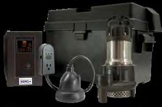
Ion StormPro 55ACi+ & 55ACi Deluxe Battery Backup System
 Page 1 of 12 1 1 5 3 2 6 3 2 6 4 5 7 55ACi+ 1. Inverter PN: TW20345 2. Battery Box, PN: U20118WOH 3. BA50M, PN: HP20162 4. Ion+ Switch/Alarm PN: inp20306 5. Ion Pipe-Mount Bracket, PN: in-spb-1 6. Battery
StormPro BA Series Sump Pump
 Page 1 of 8 Marks & Meanings DANGER: Keep the pump equipment out of the reach of children! Warns that the failure to follow the directions given could cause serious risk to individuals or objects. WARNING:
Ion Technologies WC33 Submersible Sump Pump
 Ion Technologies WC33 Submersible Sump Pump Page 1 of 8 WARNING: Risk of Fire or Explosion. Do not smoke or use open flames in or around this system. This system is not intended for use in hazardous locations
SUMPRO Battery Back-Up
 Page 1 of 12 2. Risk of electrical shock. Connect only to a properly grounded, three pronged grounding type receptacle. Under any circumstances, do not remove the grounding prong from the power cord. 3.
StormPro BCV400 Sewage Ejector Pump
 Page 1 of 8 Marks & Meanings DANGER: Keep the pump equipment out of the reach of children! Warns that the failure to follow the directions given could cause serious risk to individuals or objects. WARNING:
A+ Battery Backup Power Supply For use with Hydromatic model B-A1/BV-A1
 Unit Installation and Service Manual A+ Battery Backup Power Supply For use with Hydromatic model B-A1/BV-A1 NOTE! To the installer: Please make sure you provide this manual to the owner of the pumping
Stormpro 2100-DC. OPERATION MANUAL Heavy Duty 12V DC Pump Dated: 04/24/08 Supersedes: 02/04/08 Document No.: Spro2011-DC-OM Page 1 of 7
 Document No.: Spro2011-DC-OM Page 1 of 7 WARNING: ELECTRICAL SHOCK HAZARD This unit has not been evaluated for use outdoors - Never operate Stormpro 2100-DC outdoors. Never operate Stormpro 2100-DC with
SUMPRO Battery Back-Up
 Page 1 of 12 2. Risk of electrical shock. Connect only to a properly grounded, three pronged grounding type receptacle. Under any circumstances, do not remove the grounding prong from the power cord. 3.
Ion Technologies SHR-HR Submersible Sewage Pump Single Seal, Single Phase, & Three Phase Power
 Page 1 of 8 equipment and follow handling procedures per OSHA 29 CFR 1910.1030 when handling equipment after waste water source has been connected to system. WARNING: Risk of Asphyxiation. Installer(s)
StormPro 2100DC Heavy Duty 12V DC Pump
 Page 1 of 8 WARNING: Electrical shock hazard. This unit has not been evaluated for use outdoors. Never operate StormPro 2100DC outdoors. Never operate StormPro 2100DC with battery enclosure open. Never
OPERATION MANUAL Variable Speed Pump Controller Dated: 06/04/2013 Pump Down Application. Document No.: LMSII_V100_OM Page 1 of 8 Model-V100 LMS II
 Document No.: LMSII_V100_OM Page 1 of 8 LMS II Document No.: LMSII_V100_OM Page 2 of 8 1. Operation: When the wet well level rises above the on level set point, the lead pump will start after an adjustable
Pump Sentry. Models 812 PS & 1612 PS INSTALLATION INSTRUCTIONS
 Pump Sentry Models 812 PS & 1612 PS INSTALLATION INSTRUCTIONS The Pump Sentry is an innovative power station designed to operate your pump during a power outage. When properly installed, it will provide
MetroPrime 22MPC Self-Priming Centrifugal Pump
 Page 1 of 6 prevent priming or reduce pump capacity. OPERATION The 22 MPC-Metropolitan Pump is a self-priming centrifugal pump and only requires priming prior to its initial start. The pump will retain
ESE Series Cast Iron Sewage Pumps
 Owner s Manual ESE Series Cast Iron Sewage Pumps TABLE OF CONTENTS General Safety.................... 2 Specifications..................... 3 Installation.................... 4 & 5 Troubleshooting...................
INSTALLATION & SERVICE MANUAL
 Document No.: SBossO&M Page 1 of 19 INSTALLATION & SERVICE MANUAL SUMP BOSS MODEL BP2000 BATTERY-OPERATED SUMP PUMP WITH THE SMART CHARGER ELECTRONIC CONTROLLER SUMP BOSS THE NEW STANDARD IN BATTERY OPERATED
Ion Technologies SEF100-SEF200 Heavy Duty Sewage Pumps
 Page 1 of 12 Marks & Meanings CAUTION: Keep the pump equipment out of the reach of children! Warns that the failure to follow the directions given could cause serious risk to individuals or objects. WARNING:
Ion Technologies ES45 Effluent Pump
 Page 1 of 11 Marks & Meanings CAUTION: Keep the pump equipment out of the reach of children! Warns that the failure to follow the directions given could cause serious risk to individuals or objects. WARNING:
Owner s Manual Drill and Light Weight Portable Utility Pumps
 Owner s Manual Drill and Light Weight Portable Utility Pumps PUP61 Light Weight Utility Pump PUP62 Drill Pump with Kit PUP63 Drill Pump PUP61DC Light Weight Utility Pump LIMITED WARRANTY This pump is warranted
Matala. VersiFlow Series. Instruction and Maintenance Manual
 VersiFlow Series High Flow Multi-Purpose "Versatile " Pump V-3200 1/5HP 150W / Discharge 2 V-3900 1/3HP 250W / Discharge 2 V-4700 1/2HP 400W / Discharge 2 V-5600 1HP 750W / Discharge 2 Instruction and
SH30 High Head Effluent Pump
 Document Name: _OM Page 1 of 12 IMPORTANT: Ion Technologies is not responsible for losses, injury or death resulting from failure to observe these safety precautions, misuse, abuse or misapplication of
Matson Jump Starter Operator s Manual
 Matson Jump Starter Operator s Manual RA3800 SAVE THESE INSTRUCTIONS: This manual contains important safety and operating instructions for the RA3800 Jumpstart. Read through this owner s manual carefully
JUMP STARTER OPERATOR S MANUAL RA1900
 JUMP STARTER OPERATOR S MANUAL RA1900 SAVE THESE INSTRUCTIONS: This manual contains important safety and operating instructions for the RA1700 jump start. Read through this owner s manual carefully before
W/D/V-A1. Submersible Sump Pump. Pump Installation and Service Manual W-A1 V-A1 D-A1
 Pump Installation and Service Manual W/D/V-A1 Submersible Sump Pump W-A1 D-A1 V-A1 NOTE! To the installer: Please make sure you provide this manual to the owner of the pumping equipment or to the responsible
OWNER S MANUAL. Model YUA2AMPCH 2 AMP Dual-Bank Automatic Battery Charger & Maintainer READ ENTIRE MANUAL BEFORE USING THIS PRODUCT
 Model YUA2AMPCH 2 AMP Dual-Bank Automatic Battery Charger & Maintainer Certified by California BCS Regulations OWNER S MANUAL READ ENTIRE MANUAL BEFORE USING THIS PRODUCT READ ENTIRE MANUAL BEFORE USING
SUBMERSIBLE SUMP PUMPS
 SUBMERSIBLE SUMP PUMPS Zoeller is a registered trademark of Zoeller Co. All Rights Reserved. MODEL #1099-0001 Español p. 11 ATTACH YOUR RECEIPT HERE Serial Number Purchase Date Questions, problems, missing
GeyserMax-Flow Series
 GeyserMax-Flow Series 115V/60Hz Waterfall Pump GM-3900 1/5HP 150W / Discharge 1-1/2 GM-4700 1/3HP 250W / Discharge 2 GM-5400 1/2HP 400W / Discharge 2 GM-6200 3/4HP 750W / Discharge 2 230V/50Hz GM-3800
Pump Installation and Service Manual HRS Hydromatic Retractable System
 Pump Installation and Service Manual HRS Hydromatic Retractable System NOTE! To the installer: Please make sure you provide this manual to the owner of the pumping equipment or to the responsible party
Model: OBD-L On-Board-Diagnostics II Memory Saver Detector
 Model: OBD-L On-Board-Diagnostics II Memory Saver Detector OWNERS MANUAL IMPORTANT SAFETY INSTRUCTIONS SAVE THESE INSTRUCTIONS This manual will show you how to use your memory saver detector safely and
SUNC1200 / ITEM #40882 SUBMERSIBLE UTILITY PUMP OPERATIONS MANUAL
 SUNC1200 / ITEM #40882 SUBMERSIBLE UTILITY PUMP OPERATIONS MANUAL WWW.SUNRUNNERPOOL.COM Performance Model HP GPH of Water @ Total Feet Of Lift 0 ft. 5 ft. 10 ft. 15 ft. 20 ft. 25 ft. Max. Lift SUNC1200
24 VOLT AUTOMATIC BATTERY CHARGER PART NO
 24 VOLT AUTOMATIC BATTERY CHARGER PART NO. 957732 AC Input: DC Output: Battery Type: Specifications 230 volts, 50 hertz, 3.5 amps, single-phase 24 volts, 20 amps initially tapering to 6 amps 24 volt, 12
INSTRUCTION MANUAL. 12-Station HD Shop 12V Portable Battery Charger
 INSTRUCTION MANUAL 12-Station HD Shop 12V Portable Battery Charger IMPORTANT SAFETY INSTRUCTIONS 1. SAVE THESE INSTRUCTIONS This manual contains important safety and operating instructions for your HD
SPC-PANEL Simplex, Single Phase Pump Control Panel
 Pump Installation and Service Manual SPC-PANEL Simplex, Single Phase Pump Control Panel Pump Controls for 2 HP Grinder Pumps NOTE! To the installer: Please make sure you provide this manual to the owner
SUBMERSIBLE SUMP PUMPS
 SUBMERSIBLE SUMP PUMPS Zoeller is a registered trademark of Zoeller Co. All Rights Reserved. MODELS #1073-0001, 1075-0001 Español p. 9 ATTACH YOUR RECEIPT HERE Serial Number Purchase Date Questions, problems,
MODEL A96 SERIES. 130Vdc Switchmode Utility Rectifier / Battery Charger. Used with LaMarche Power Cage ECN/DATE
 MODEL A96 SERIES 130Vdc Switchmode Utility Rectifier / Battery Charger Used with LaMarche Power Cage CPN112138 ECN/DATE ISSUE DATE: ECN 17010-12/05 106 BRADROCK DRIVE DES PLAINES, IL. 60018-1967 (847)
S33 Sump Pump INSTRUCTIONS AND SERVICE MANUAL VERTICAL FLOAT SWITCH S33V1 & S33V1C AUTOMATIC S33P1 & S33PC-1 (CONTROL WITH SERIES PLUG) NOT SHOWN
 NOT SHOWN") S33 Sump Pump INSTRUCTIONS AND SERVICE MANUAL VERTICAL FLOAT SWITCH S33V1 & S33V1C AUTOMATIC S33P1 & S33PC-1 (CONTROL WITH SERIES PLUG) NOT SHOWN AUTOMATIC S33A1 & S33A1C WARNING risk of electric shock.
S33 Sump Pump INSTRUCTIONS AND SERVICE MANUAL VERTICAL FLOAT SWITCH S33V1 & S33V1C AUTOMATIC S33P1 & S33PC-1 (CONTROL WITH SERIES PLUG) NOT SHOWN AUTOMATIC S33A1 & S33A1C WARNING risk of electric shock.
CP series. Submersible utility pump 50HZ STAIRS INDUSTRIAL CO., LTD.
 CP series Submersible utility pump 50HZ STAIRS INDUSTRIAL CO., LTD. CP SERIES - Submersible utility pump The STAIRS CP series submersible utility pump is designed for dewatering and groundwater transferring
GRINDER PUMP MODEL # Zoeller is a registered trademark of Zoeller Co. All Rights Reserved. Español p. 13
 GRINDER PUMP Zoeller is a registered trademark of Zoeller Co. All Rights Reserved. MODEL #2701-0005 Español p. 13 ATTACH YOUR RECEIPT HERE Serial Number Purchase Date Questions, problems, missing parts?
SUNC3000 / Item #40885
 SUNC3000 / Item #40885 AUTOMATIC POOL COVER PUMP OPERATIONS MANUAL WWW.SUNRUNNERPOOL.COM 1 . Performance GPH of Water @ Total Feet Of Lift MODEL HP Max. Lift 0 ft. 5 ft. 10 ft. 15 ft. 20 ft. SUNC3000 1/3
Nature Power Inverters. True Sinewave Inverter Modified Sinewave Inverter. Owner s Manual
 Version 1.1 Version 2 Nature Power Inverters True Sinewave Inverter Modified Sinewave Inverter Owner s Manual!!!!!!!!!!! 38304 38204 For safe and optimum performance, the Power Inverter must be used properly.
AUTO CHARGE D2 MODEL #: AUTOMATIC TRIPLE OUTPUT BATTERY CHARGER INSTRUCTION MANUAL
 INSTRUCTION MANUAL AUTO CHARGE D2 AUTOMATIC TRIPLE OUTPUT BATTERY CHARGER Designed Specifically for Vehicles with DDEC ENGINES MODEL #: 091-74-12 INPUT: 120 Volt, 60 Hz, 8 Amps OUTPUT VEHICLE BATTERY 1
MODEL 2602A-12 3 STAGE AUTOMATIC BATTERY CHARGER OWNER S MANUAL SAVE THESE INSTRUCTIONS
 R A Valley Forge Company MODEL 2602A-12 3 STAGE AUTOMATIC BATTERY CHARGER OWNER S MANUAL SAVE THESE INSTRUCTIONS 1. INTRODUCING THE CHARGER The 2602A-12 is a 3-stage electronic battery charger. Rainproof,
AUTO CHARGE DUAL MODEL #: AUTOMATIC DUAL OUTPUT BATTERY CHARGER INSTRUCTION MANUAL. Ph: Fax:
 INSTRUCTION MANUAL AUTO CHARGE DUAL AUTOMATIC DUAL OUTPUT BATTERY CHARGER MODEL #: 091-145-12 INPUT: 120 Volt, 50/60 Hz, 3.5 Amps OUTPUT BAT 1: 10 Amps OUTPUT BAT 2: 10 Amps File: IM_091-145-12_revb.indd
AUTOMATIC SUBMERSIBLE UTILITY PUMP
 AUTOMATIC SUBMERSIBLE UTILITY PUMP Zoeller is a registered trademark of Zoeller Co. All Rights Reserved. MODEL #1043-0006 Español p. 9 ATTACH YOUR RECEIPT HERE Serial Number Purchase Date Questions, problems,
Power Inverter 400 MW Owner s Manual
 Power Inverter 400 MW 1204 Owner s Manual For safe and optimum performance, the Power Inverter must be used properly. Carefully read and follow all instructions and guidelines in this manual and give special
AUTO CHARGE 12 HO MODEL #: MODEL #: MODEL #: AUTOMATIC SINGLE OUTPUT BATTERY CHARGER INSTRUCTION MANUAL
 INSTRUCTION MANUAL AUTO CHARGE 12 HO AUTOMATIC SINGLE OUTPUT BATTERY CHARGER MODEL #: 091-170-6 MODEL #: 091-170-12 MODEL #: 091-170-24 File: IM_091-170-xx_revd.indd Rev: D Revised By: MFG Date: 10-23-2013
Model: SE-4020-CA Automatic Battery Charger
 OWNERS MANUAL Model: SE-4020-CA Automatic Battery Charger PLEASE SAVE THIS OWNERS MANUAL AND READ BEFORE EACH USE. This manual will explain how to use the battery charger safely and effectively. Please
Operating Instructions for PAC800 Battery Charger
 Operating Instructions for PAC800 Battery Charger General Safety The charger may only be used for the specified battery types. This battery charger is supplied with pre-set charging curves that are adapted
Installation Operation Parts
 OWNER S MANUAL BATTERY BACKUP SUMP Installation Operation Parts For further operating, installation or maintenance assistance, Call 98-8-05 PRINTED IN U.S.A. M-8 (/9) RULES FOR SAFE INSTALLATION AND OPERATION
OWNER S MANUAL INSTALLATION AND OPERATION INSTRUCTIONS
 OWNER S MANUAL INSTALLATION AND OPERATION INSTRUCTIONS CAST IRON SUBMERSIBLE SUMP PUMP MODEL: BASPC33V If for any reason you have questions concerning your new Barracuda Pump, call us toll free at 1-844-251-7445.
OWNER S MANUAL. INSTALLATION AND OPERATION INSTRUCTIONS FOR 12 VOLT BATTERY BACK-UP SYSTEM Models: 92900, 92910
 OWNER S MANUAL INSTALLATION AND OPERATION INSTRUCTIONS FOR 12 VOLT BATTERY BACK-UP SYSTEM Models: 92900, 92910 If for any reason you have questions concerning your new Superior Pump, call us toll free
AUTO CHARGE D PUMP PLUS
 INSTRUCTION MANUAL AUTO CHARGE D PUMP PLUS AUTOMATIC DUAL OUTPUT BATTERY CHARGER Designed Specifically for Vehicles with DDEC ENGINES MODEL #: 091-9-DPP INPUT: 120 Volt, 60 Hz, 8 Amps OUTPUT VEHICLE BATTERY:
SEWAGE PUMP MODEL # Zoeller is a registered trademark of Zoeller Co. All Rights Reserved. Español p. 14
 SEWAGE PUMP Zoeller is a registered trademark of Zoeller Co. All Rights Reserved. MODEL #1261-0001 Español p. 14 ATTACH YOUR RECEIPT HERE Serial Number Purchase Date Questions, problems, missing parts?
Pump Installation and Service Manual JB-1 System Sewage Ejector Pump Package
 Pump Installation and Service Manual JB-1 System Sewage Ejector Pump Package NOTE! To the installer: Please make sure you provide this manual to the owner of the pumping equipment or to the responsible
PEDESTAL SUMP PUMP. MODEL # Español p. 11. Zoeller is a registered trademark of Zoeller Co. All Rights Reserved.
 PEDESTAL SUMP PUMP Zoeller is a registered trademark of Zoeller Co. All Rights Reserved. MODEL #1084-0001 Español p. 11 ATTACH YOUR RECEIPT HERE Serial Number Purchase Date Questions, problems, missing
Safety, Installation And Operating Instructions For The Following Battery Charger Models: i2412, i3612, i4809, i2425, i3625, and i4818
 Safety, Installation And Operating Instructions For The Following Battery Charger Models: i2412, i3612, i4809, i2425, i3625, and i4818 IMPORTANT NOTICE: Please save and read these safety, operating and
STEP-BY-STEP INSTALLATION GUIDE
 Battery Backup System STEP-BY-STEP INSTALLATION GUIDE Operating Instructions & Parts Manual ESP25 Please read and save these instructions. Read carefully before attempting to assemble, install, operate
Pump Installation and Service Manual SP40 Submersible Sewage Ejector Pump
 Pump Installation and Service Manual SP40 Submersible Sewage Ejector Pump NOTE! To the installer: Please make sure you provide this manual to the owner of the pumping equipment or to the responsible party
PUMP PLUS 2000 PLC MODEL #: PP AUTOMATIC DUAL OUTPUT BATTERY CHARGER INSTRUCTION MANUAL
 INSTRUCTION MANUAL PUMP PLUS 2000 PLC AUTOMATIC DUAL OUTPUT BATTERY CHARGER Supplied with Dual Bar Graph Display MODEL #: 091-237-12-PP INPUT: 120 Volt, 60 Hz, 3.5 Amps OUTPUT BATTERY 1 and 2: 15 or 18
2603 Battery Pal 3 AMP, 1 2 VOLT BATTERY CHARGER
 R 2603 Battery Pal 3 AMP, 1 2 VOLT BATTERY CHARGER Connections at a glance: The GUEST Battery Pal 2603 is designed to recharge your battery, and extend your battery s life in applications where it is stored
MM-AVR UPS Series User s Manual
 MM-AVR UPS Series User s Manual TABLE OF CONTENTS Safety Instructions... 2 Description... 2 Determining Power Requirements... 3 Hardware Installation Guide... 3 Battery Replacement Instructions... 4 LED
PUMP PLUS 1000 PLC MODEL #: PP AUTOMATIC SINGLE OUTPUT BATTERY CHARGER INSTRUCTION MANUAL
 INSTRUCTION MANUAL PUMP PLUS 1000 PLC AUTOMATIC SINGLE OUTPUT BATTERY CHARGER Unit supplied with one of these displays MODEL #: 091-215-12-PP INPUT: 120 Volt, 60 Hz, 3.5 Amps OUTPUT BATTERY 1 and 2: 15
LESTRONIC II BATTERY CHARGER BUILT-IN OR PORTABLE CHARGERS
 LESTRONIC II BATTERY CHARGER BUILT-IN OR PORTABLE CHARGERS PLEASE SAVE THESE IMPORTANT SAFETY AND OPERATING INSTRUCTIONS For correct operation of the equipment, it is important to read and be familiar
AUTO CHARGE 4000 MODEL #: AUTOMATIC DUAL OUTPUT BATTERY CHARGER INSTRUCTION MANUAL. Ph: Fax:
 INSTRUCTION MANUAL AUTO CHARGE 4000 AUTOMATIC DUAL OUTPUT BATTERY CHARGER MODEL #: 091-89-12 INPUT: 120 Volt, 50/60 Hz, 8 Amps OUTPUT BATTERY CHARGER: 40 Amps OUTPUT BATTERY SAVER: 5 Amps File: IM_091-89-12_reve.indd
IMPORTANT SAFETY INSTRUCTIONS IMPORTANT: READ AND SAVE THIS SAFETY AND INSTRUCTION MANUAL. KEEP IT WITH OR NEAR CHARGER AT ALL TIMES.
 IMPORTANT SAFETY INSTRUCTIONS IMPORTANT: READ AND SAVE THIS SAFETY AND INSTRUCTION MANUAL. KEEP IT WITH OR NEAR CHARGER AT ALL TIMES. SPECIFICATIONS: For technical assistance, call your Dealer with the
LPC 20 MODEL #: LOW PROFILE CHARGER AUTOMATIC SINGLE OUTPUT BATTERY CHARGER INSTRUCTION MANUAL
 INSTRUCTION MANUAL LPC 20 LOW PROFILE CHARGER AUTOMATIC SINGLE OUTPUT BATTERY CHARGER Unit supplied with one of these displays MODEL #: 091-207-12 INPUT: 120 Volt, 50/60 Hz, 7 Amps OUTPUT: 20 Amps File:
IMPORTANT SAFETY INSTRUCTIONS
 1163714 1.5 AMP 12VOLT TRICKLE 1.5 AUTOMATIC AMP AUTOMATIC TRICKLE 1.5 AMP AUTOMATIC 12V12VOLT BATTERY CHARGER IMPORTANT SAFETY INSTRUCTIONS 1. SAVE THESE INSTRUCTIONS This product offers a wide range
Cruising Charger Series OWNER S MANUAL
 R Cruising Charger Series OWNER S MANUAL ON BOARD BATTERY CHARGERS Models DC Amperage No. Of Banks Volts 2614A 5,10 Amps 2 Bank 12/12 2614A-230 2621A 5,5,10 Amps 3 Banks 12/12/12 2621A-230 2622A 10,10
OPERATING INSTRUCTIONS. Note: 6V Charging. Requires Manual Shut Off.
 Requires Manual Shut Off. 6 / 2 AMP,, DUAL RATE BATTER TTERY CHARGER 45005 OPERATING INSTRUCTIONS E224783 E224783 Note: 6V Charging Due to continuing improvements, actual product may differ slightly from
PSJ-2212, PSJ-3612, PSJ-4424
 Model: PSJ-2212, PSJ-3612, PSJ-4424 Jump Starter and DC Power Source OWNER S MANUAL PSJ-2212 PLEASE SAVE THIS OWNER S MANUAL AND READ BEFORE EACH USE. This manual will explain how to use your jump starter
MODEL A97 SERIES. Switchmode Utility Rectifier/Battery Charger ECN/DATE
 MODEL A97 SERIES Switchmode Utility Rectifier/Battery Charger CPN108172 ISSUE DATE: 16071 7/03 ECN/DATE 106 BRADROCK DRIVE DES PLAINES, IL. 60018-1967 (847) 299-1188 FAX: (847)299-3061 Page 1 of 7 INSTRUCTION
ME3H/ME3F SERIES. Automatic and manual models. Single phase power only 115 or 230 volt.
 ME3H SUMP/EFFLUENT PUMP ME3F SUMP/EFFLUENT PUMP ME3H/ME3F SERIES SUBMERSIBLE SUMP AND EFFLUENT PUMPS INSTALLATION AND SERVICE MANUAL Automatic and manual models. Single phase power only 115 or 230 volt.
LPC 40 MODEL #: LOW PROFILE CHARGER WITH PLC AUTOMATIC SINGLE OUTPUT BATTERY CHARGER INSTRUCTION MANUAL
 INSTRUCTION MANUAL LPC 40 LOW PROFILE CHARGER WITH PLC AUTOMATIC SINGLE OUTPUT BATTERY CHARGER Unit supplied with one of these displays MODEL #: 091-200-12 INPUT: 120 Volt, 50/60 Hz, 5 Amps OUTPUT: 40
801 BUSINESS CENTER DRIVE MOUNT PROSPECT, ILLINOIS
 280-600 Send Warranty Product Repairs to: 1025 E. Thompson Ave., Hoopeston, IL 60942-0280. Call Customer Service if you have questions: 1-800-621-5485 A. IMPORTANT SAFETY INSTRUCTIONS 1. SAVE THESE INSTRUCTIONS
AUTO CHARGE 4000 MODEL #: LOW PROFILE CHARGER AUTOMATIC DUAL OUTPUT BATTERY CHARGER INSTRUCTION MANUAL
 INSTRUCTION MANUAL AUTO CHARGE 4000 LOW PROFILE CHARGER AUTOMATIC DUAL OUTPUT BATTERY CHARGER Unit supplied with this display MODEL #: 091-89-12 INPUT: 120 Volt, 50/60 Hz, 5 Amps OUTPUT: 45 Amps File:
10 AMP ON BOARD BATTERY CHARGER
 R A Valley Forge Company MODEL 2611A-1-B 10 AMP ON BOARD BATTERY CHARGER One Output OWNER S MANUAL IMPORTANT! READ THESE INSTRUCTIONS BEFORE INSTALLING AND USING THIS PRODUCT. Keep these instructions for
User Guide IGD Series
 US User Guide IGD Series DANGER PRIOR TO USE, READ AND UNDERSTAND PRODUCT SAFETY INFORMATION. Failure to follow the instructions may result in ELECTRICAL SHOCK, EXPLOSION, or FIRE, which may result in
Sentry Battery Charger. Installation and Operations Manual Section 75
 Sentry Battery Charger Installation and Operations Manual 00-02-0616 03-03-08 Section 75 In order to consistently bring you the highest quality, full featured products, we reserve the right to change our
READ THIS MANUAL CAREFULLY BEFORE USING THE PUMP
 OWNER S MANUAL Pond Pump READ THIS MANUAL CAREFULLY BEFORE USING THE PUMP Important Notice: This manual contains important information about the installation, operation and safe use of this product. This
INSTALLATION & OPERATION MANUAL
 INSTALLATION & OPERATION MANUAL PRE-ASSEMBLED PRIMARY & BATTERY BACK-UP SUMP PUMP SYSTEM 5030CVSPBUSS, 5033CVSPBUSS www.aymcdonald.com A.Y. McDonald BBU Manual Revised 8-13 3210-479 Rev. A 12 This pump
PRE-PLUMBED SEWAGE SYSTEM
 PRE-PLUMBED SEWAGE SYSTEM Zoeller is a registered trademark of Zoeller Co. All Rights Reserved. MODEL #1910-0009 Español p. 13 ATTACH YOUR RECEIPT HERE Serial Number Purchase Date Questions, problems,
SP6. Automatic Battery Charger. Model
 Model SP6 Automatic Battery Charger OWNERS MANUAL PLEASE SAVE THIS OWNERS MANUAL AND READ BEFORE EACH USE. This manual will explain how to use the charger safely and effectively. Please read and follow
BATTERY SAVER LOW RIPPLE HO
 INSTRUCTION MANUAL BATTERY SAVER LOW RIPPLE HO LOW RIPPLE POWER SUPPLY / AUTOMATIC LOAD SWITCH FOR 12VDC VEHICLE SYSTEMS MODEL #: 091-195-12 INPUT: 120 Volt, 50/60 Hz, 4.5 Amps RMS OUTPUT: 13.2 Volts DC,
LESTRONIC II BATTERY CHARGER MODEL 19740
 *01679* LESTRONIC II BATTERY CHARGER MODEL 19740 PLEASE SAVE THESE IMPORTANT SAFETY AND OPERATING INSTRUCTIONS For correct operation of the equipment, it is important to read and be familiar with this
SAVE THESE INSTRUCTIONS
 R MODEL 2611 10 AMP ON BOARD BATTERY CHARGER Two Outputs OWNER S MANUAL Connections at a glance: For the best charging results both 12 Volt independent batteries should be equally discharged. The charger
A48 / A48B (base plate) BATTERY CHARGER
 BATTERY CHARGER") A48 / A48B (base plate) BATTERY CHARGER CPN41054 ISSUE DATE: 12315-8/98 ECN/DATE 106 BRADROCK DRIVE DES PLAINES, IL. 60018-1967 (847) 299-1188 FAX: (847)299-3061 15349-07-07/02 16041 6/03 14575-2/01 INSTRUCTION
A48 / A48B (base plate) BATTERY CHARGER CPN41054 ISSUE DATE: 12315-8/98 ECN/DATE 106 BRADROCK DRIVE DES PLAINES, IL. 60018-1967 (847) 299-1188 FAX: (847)299-3061 15349-07-07/02 16041 6/03 14575-2/01 INSTRUCTION
ADI-125/750 ADI-125/1500 ADI-125/2500
 Manufacturer of Dimensions TM Inverters 4467 White Bear Parkway St. Paul, MN 55110 Phone: 651-653-7000 Fax: 651-653-7600 E-mail: inverterinfo@sensata.com Web: www.dimensions.sensata.com 121094B OWNERS
BC-9000 OPERATIONS MANUAL BATTERY CHARGER COFKO ELECTRONICS LLC COPYRIGHT 2014 P/N
 BC-9000 BATTERY CHARGER OPERATIONS MANUAL COFKO ELECTRONICS LLC COPYRIGHT 2014 P/N 4169-20 UNPACKING As you unpack your new BC-9000 battery charger, inspect the BC-9000 for signs of shipping damage. If
Smart Battery Charger GPC-35-MAX GPC-45-MAX GPC-55-MAX GPC-75-MAX GPC-100-MAX. Owner s Manual
 Smart Battery Charger GPC-35-MAX GPC-45-MAX GPC-55-MAX GPC-75-MAX GPC-100-MAX Owner s Manual Table of Contents Important Safety Instructions 2 Features 3 Installation Guidelines 5 Warranty 8 1.0 Important
BusPro Series Instruction Manual
 Test Equipment Auto Meter Products Inc. 413 West Elm Street Sycamore, IL 60178 12 Toll Free (866) 883-TEST (8378) Fax (815)-895-6786 www.autometer.com 2650-505X-10 Rev. E Professional BusPro Series Instruction
installation and operating instructions for the following xtreme Battery chargers:
 installation and operating instructions for the following xtreme Battery chargers: Model Name No. of Banks Amps Per Bank Battery System Dual Pro SE Xtreme Dual Pro Xtreme Three Bank SE Xtreme Three Bank
POWER TO GET THE JOB DONE
 52722 10 AMP 12 VOLT BATTERY CHARGER OWNER S MANUAL OVERCHARGING PROTECTION 10 Amp, 12 Volt Fully automatic and manually selectable Includes overcharging protection in automatic mode Reverse hook-up protection
DC to AC Power Inverters
 Manufacturer of Dimensions TM Inverters 4467 White Bear Parkway St. Paul, MN 55110 Phone: 651-653-7000 Fax: 651-653-7600 E-mail: inverterinfo@sensata.com Web: www.dimensions.sensata.com ISO 9001:2000 Certified
A39 UNIVERSAL SCR CHARGER
 A39 UNIVERSAL SCR CHARGER ECN/DATE CPN35971 21681 01/18 16816-6/05 15349-03 05/02 14575 02/01 14268 10/00 10400 9/96 106 BRADROCK DRIVE DES PLAINES, IL. 60018-1967 (847) 299-1188 FAX: (847) 299-3061 ISSUE
ELECTRONIC MARINE CONVERTER/CHARGER Owners Manual Models PD2020, PD2030, PD2040, PD2050, PD2060, PD2080
 Table Of Contents ELECTRONIC MARINE CONVERTER/CHARGER Owners Manual Models PD2020, PD2030, PD2040, PD2050, PD2060, PD2080 Thank you for purchasing the INTELI-POWER MARINE converter/charger. The INTELI-POWER
801 BUSINESS CENTER DRIVE MOUNT PROSPECT, ILLINOIS Ext. 322
 277-999 ELECTRIC CORP. 801 BUSINESS CENTER DRIVE MOUNT PROSPECT, ILLINOIS 800-621-5485 Ext. 322 Send Warranty Product Repairs to: 605 South Vermilion, Suite C, Brownsville, TX 78521-6851 Call Customer
DC to AC Power Inverters
 Manufacturer of Dimensions TM Inverters 4467 White Bear Parkway St. Paul, MN 55110 Phone: 651-653-7000 Fax: 651-653-7600 E-mail: inverterinfo@sensata.com Web: www.dimensions.sensata.com 121114C OWNERS
Models: SP3, SPSS3 Automatic Battery Charger
 OWNERS MANUAL Models: SP3, SPSS3 Automatic Battery Charger PLEASE SAVE THIS OWNERS MANUAL AND READ BEFORE EACH USE. This manual will explain how to use the charger safely and effectively. Please read and
BATTERY & STARTER ANALYSER (BSA-12) User Manual
 User Manual") BATTERY & STARTER ANALYSER (BSA-12) User Manual Introduction BSA-12 Battery Starter Analyser does not carry internal batteries but is powered up from external DC source ranging from 9V to 15V DC. It is
BATTERY & STARTER ANALYSER (BSA-12) User Manual Introduction BSA-12 Battery Starter Analyser does not carry internal batteries but is powered up from external DC source ranging from 9V to 15V DC. It is
OWNER S MANUAL SUBMERSIBLE UTILITY PUMP
 Model 51101-0 OWNER S MANUAL SUBMERSIBLE UTILITY PUMP Questions, problems, missing parts? Before returning to the store call AQUAPRO Customer Service 8 a.m. - 5 p.m., EST, Monday-Friday 1-844-242-2475
OWNER S MANUAL SELF-PRIMING PORTABLE UTILITY PUMP
 Model 54011-0 OWNER S MANUAL SELF-PRIMING PORTABLE UTILITY PUMP Questions, problems, missing parts? Before returning to the store call AQUAPRO Customer Service 8 a.m. - 5 p.m., EST, Monday-Friday 1-844-242-2475