Installation Guide
|
|
|
- Bruce Park
- 5 years ago
- Views:
Transcription
1 Solar Generator Installation Guide
2 Contents 1 Important Safety Instructions 2 Introduction 3Planning 4 Installation 1
3 A Specifications 2
4 About This Guide About This Guide Purpose Scope Audience Organization 3
5 About This Guide Conventions Used WARNING CAUTION Abbreviations and Acronyms Related Information Important: Abbreviation or Acronym Definition 4
6 Important Safety Instructions WARNING General Precautions Precaution for Solar anel About This Guide 5
7 About This Guide ² º 6
8 About This Guide Precaution for PowerHub 1800 WARNING: Limitations on use WARNING (Operator's Guide) 6 7

9 About This Guide Basic Safety 8
10 About This Guide Reorient or relocate the receiving antenna. Increase the separation between the equipment receiver. Connect the equipment into an outlet on a circuit different from that to which the receiver is connected. Consult the dealer or an experienced radio/tv technician for help. Power Down Procedure If softwired... To Power Down the PowerHub 1800: 2 Press ON/OFF Switch to turn OFF Inverter/Charger 1 Disconnect Loads 4 Disconnect the Battery Box(es) from the Inverter 3 Disconnect the PowerHub from the generator and turn the generator OFF. OFF Power Down Procedure for Softwired Installations 9
11 About This Guide If hardwired... To Power Down the PowerHub 1800: WARNING: Shock Hazard If no DC disconnect is used, then the DC input sources (solar or wind) will have to be physically disconnected to ensure power is OFF. 1 Disconnect any loads directly connected to the front panel of the PowerHub 2 Disconnect Loads connected to the PowerHub through AC Distribution Panel (Sub-panel) by opening the Inverter Output Circuit Breaker. 3 Press ON/OFF Switch to turn OFF Inverter/Charger 4 Disconnect the DC Input.(s) 6 Disconnect the Battery Box(es) from the Inverter 5 Disconnect the Utility power by opening the AC input circuit breaker in the main panel. Power Down Procedure for Hardwired Installations 10
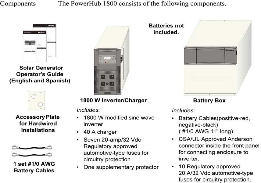
12 2 Introduction Chapter 2 describes the features and functions of the Solar Generator. The PowerHub


13 Introduction Features and Functions 12
14 13 Introduction
15 Inverter Features Introduction The inverter consists of the following user features: Inverter Control Panel Four 120 Vac outlets on the front panel. One supplementary protector to protect the 120 Vac outlets from overload. Two Battery Box Connection Ports (one on each side) Input/Output terminals are located under top panel. See Figure on page for a detailed illustration of these terminals. Inverter Control Panel AC Outlets (x4) Battery Box Connection Ports for Anderson-type Connector Plus (x2-one on each side) AC Indicator LED Supplementary Protector 1800 Features Input/Output Terminals The inverter has the following input/output terminals: Two DC Anderson ports for 12 V battery connections from the Battery Box; one on each side. Two pairs of DC input terminals for renewable energy connections: one 32 A input terminal and one 80 A input terminal. External inputs to these terminals must be externally regulated. Solar panels must use charge controllers and wind turbines must be self-regulated. The 32 A terminals can be used for 12 Vdc input up to 400 W maximum. The 80 A terminals can be used for 12 Vdc input up to 1000 W maximum. AC input terminal (for grid or generator input) AC output terminal (for AC output in hardwired installations) 14
16 Introduction Grounding The inverter has two AC Ground terminals and one equipment ground terminal. In addition, there are ground fault protection terminals for solar and wind renewable energy inputs (a 32 A and an 80 A). See Figure on page for a detailed illustration of the Input/Output and ground terminals. Regulatory Th complies with CSA and UL1741and is a permanent installation that is compliant with national electrical codes. 15
17 Introduction Applications The Solar Generator could be a home backup power, an emergency power or a small/home office backup power. Important: Installations of this kind must be certified/approved as code-compliant to the national and local building and electrical codes. Installers should have adequate knowledge of national and local code to ensure the installation passes inspection by the local electric authority. Example only. Actual installation may vary. Solar Panel AC Distribution Panel (Sub-Panel) 50 12AWG cable Charge Controller 8 12AWG cable AC OUT DC IN Important:The combination of loads cannot exceed 1440 W. Run-times will depend on the amp-hour rating of the batteries. H 16


18 Introduction Applications Important: Installations of this kind must be certified/approved as code-compliant to the national and local building and electrical codes. Installers should have adequate knowledge of national and local code to ensure the installation passes inspection by the local electric authority. Example only. Actual installation may vary. Solar Panel AC Distribution Panel (Sub-Panel) 50 12AWG cable Charge Controller 8 12AWG cable AC OUT DC IN Important:The combination of loads cannot exceed 1440 W. Run-times will depend on the amp-hour rating of the batteries. Figure Emergency power 17


19 Introduction Applications Important: Installations of this kind must be certified/approved as code-compliant to the national and local building and electrical codes. Installers should have adequate knowledge of national and local code to ensure the installation passes inspection by the local electric authority. Example only. Actual installation may vary. Solar Panel AC Distribution Panel (Sub-Panel) 50 12AWG cable Charge Controller 8 12AWG cable AC OUT DC IN Important:The combination of loads cannot exceed 1440 W. Run-times will depend on the amp-hour rating of the batteries. Figure Office back-up power 18

20 Introduction Hardwired Permanent Applications Utility Backup Applications Important: Installations of this kind must be certified/approved as code-compliant to the national and local building and electrical codes. Installers should have adequate knowledge of national and local code to ensure the installation passes inspection by the local electric authority. Example only. Actual installation may vary. AC Distribution Panel (Sub-Panel) Main AC Panel AC OUT AC IN 120 Vac Outlets Important: The combination of loads cannot exceed 1440 W. Run-times will depend on the amp-hour rating of the batteries. Hardwired Utility Applications 19

21 Introduction Wind Applications Important: Installations of this kind must be certified/approved as code-compliant to the national and local building and electrical codes. Installers should have adequate knowledge of national and local code to ensure the installation passes inspection by the local electric authority. Maximum size of wind turbine: 1000 W maximum on 80 A DC terminal only Self-regulation required. Disconnect recommended Example only. Actual installation may vary. Wind Turbine AC Distribution Panel (Sub-Panel) DC Disconnect (recommended) AC OUT DC IN Important: The combination of loads cannot exceed 1440 W. Run-times will depend on the amp-hour rating of the batteries. Hardwired Wind Applications 20

22 Introduction Combination Applications The PowerHub 1800 can be used for the other entry-level applications as well. Important: Installations of this kind must be certified/approved as code-compliant to the national and local building and electrical codes. Installers should have adequate knowledge of national and local code to ensure the installation passes inspection by the local electric authority. Example only. Actual installation may vary. Solar Panel(s) and Charge Controller(s) Wind Turbine (Must be self-regulated) AC Distribution Panel (Sub-Panel) Main AC Distribution Panel AC IN DC IN DC Disconnects (recommended) DC IN AC OUT Important:The combination of loads cannot exceed 1440 W. Run-times will depend on the amp-hour rating of the batteries. Hardwired Combination Applications 21
 The PowerHub 1800 comes assembled with an AC input cord. This AC cord can be plugged into a 120 Vac outlet on a generator to charge the batteries.")
23 Applications Introduction The PowerHub 1800 can be used for the following entry-level applications. Softwired Generator Applications (Plug-and-go) The PowerHub 1800 comes assembled with an AC input cord. This AC cord can be plugged into a 120 Vac outlet on a generator to charge the batteries. Important: The input cord is intended to allow connection to portable generators in non-permanent installations. For fixed permanent installations, Xantrex recommends using electrical code-compliant wiring methods. Important: The total amount of output power available to power the loads is 1440 watts, due to the 15 A supplementary protector which protects the circuitry. AC Generator 120 Vac Outlet AC OUT Important: The combination of loads cannot exceed 1440 W. Run-times will depend on the amp-hour rating of the batteries. Softwired Utility or Generator Applications 22
24 3 Planning 23
25 Planning Planning Overview Important: This unit is intended as an entry-level inverter/charger backup system. To use it as a stand-alone power source, it is not required to do any special installation procedures. However, if your installation involves renewable energy (solar or wind generators) or requires hardwiring for any reason, if you do not have adequate knowledge of national and local building and electrical codes, do not attempt to install this unit in a permanent installation. Consult your local renewable energy dealer or qualified electrician for assistance. 1. Plan your installation carefully 2.etermine if the installation will be softwired hardwired. If hardwired, are there any special permits required. 3. Know your limits. Know the limits of the loads to be attached to the system. Know the limits of the input and output to the inverter and the batteries. Know the electrical and building code requirements for the desired location. Analyze the location for the PowerHub for access and adequate structural support. Measure the distances for the cabling and wiring. 4. Extract thepowerhub from packaging material and parts to ensure there is nothing missing. 5. Review all instructions and materials provided with all the equipment. 6. Review all material provided with the batteries. 7. Review any material related to the installation of the renewable energy components. 8. Collect all necessary tools and materials for the installation. 9. Prepare the location for the installation and position the components. 24
26 Tools Required The following tools may be required for installing this equipment: #2 Phillips screwdriver(s) Slotted screwdriver(s) Wire strippers Torque wrench Socket wrench and sockets (½ in. for the wind DC input terminal, and 10 mm for the solar DC input terminal) Electrical tape Hardware / Materials Required The following customer supplied items are required One or two 12 Vdc SEALED (100 amp-hour), lead-acid batteries. 1 ground cable #3 AWG copper (length to be determined by the location of the installation) The following items may be required for completing this installation. Electrical wire of appropriate gauge and length for AC input, AC output, and AC ground (length to be determined by the location of the installation). See Table on page. Conduits and appropriate fittings for wire runs (e.g., wire nuts) Breaker panels, 15 A circuit breakers and appropriately sized DC disconnects Wire connectors and crimp tool for the wind and solar DC cables Environmental Requirements Planning Ventilation Ensure the environment where the PowerHub is to be installed is properly ventilatedfree of dust, dirt, etc. and where the temperature will not fall below 0 C (32 F) or rise above Clearance Ensure there is a minimum of 8 inches (preferably 12 inches) of clearance around all ventilation holes and vents. Ensure nothing flammable is stored anywhere near this unit. Be sure to leave adequate room to access the terminals if the unit is to be hardwired. Twelve inches may not be adequate for access purposes to hardwire the unit. 25

 14.25 (35.56 cm) 14 (35.56 cm) 8 (20.32 cm) 22 (55.88 cm) Dimensions (not to scale) 13.875 (35.24 cm) Recommended Minimum Required Floor Space = 22\" (55.")
27 Planning Sunlight Choose an appropriate location that provides the most direct sunlight and can support the solar panel, and is free from shade. Be aware of surrounding objects which may obscure the sun from the panel. This solar panel is weatherproof including UV protection and protecting from rain, snow, storm and anyzweather effects of -35 o F 175 o F (-37 o C - 79 o C). Dimensions 16 (40.64 cm) 20.5 (52.7 cm) (35.56 cm) 14 (35.56 cm) 8 (20.32 cm) 22 (55.88 cm) Dimensions (not to scale) (35.24 cm) Recommended Minimum Required Floor Space = 22" (55.88 cm) x 33" (84 cm) Back 33 (84 cm) 12" Clearance 29 (73.7 cm) 20.5 (52.7 cm) 8" Clearance Equipment Footprint Front IMPORTANT: The Powerhub should be mounted on concrete floors or on floors designed to support a minimum load of 100 pounds per square foot. IMPORTANT: Allow 8" minimum clearance around the back of this unit for ventilation. (12" preferable). Be sure to leave adequate space for access if the unit is to be hardwired. 12" may not be adequate. 26
28 Planning Batteries Important: The PowerHub 1800 is designed to be permanently connected to a small 12-volt battery bank. Do not operate this equipment without connecting a battery or battery bank. Types to use The PowerHub will use the power stored in the batteries to run AC loads up to 1440 W (continuously). Run times for the AC loads will depend on the amp-hour capacity of the batteries and the total of the loads drawing power through the unit. The following battery types are recommended for use with the PowerHub 1800: Voltage 12 Vdc (required) (100 Ah minimum) Chemistry SEALED, lead-acid batteries (required), Gel-type (recommended), AGM (acceptable) Size Standard Group 27. Maximum dimension of battery to be 12" W 6.75" D 9" H (including terminal posts) Terminal Location Top (required) Terminal Type L-type or screw-in terminal WARNING: Shock hazard Terminal adaptors are not acceptable as they may short circuit to the battery box, and cause an energy hazard. Battery Box Internal dimensions 12.75" W x 16"D 12.75" 16" Battery Box holds 2 Standard Sealed Lead-acid 12 Vdc Batteries* sized 12" W 6.75" D 9" H 12" 6.75" 9" Battery Box and Battery Size 27
29 Planning Important: All batteries used for this system should be identical. Do not mix battery types or sizes. Do not mix old batteries with new batteries. Performance and charging anomalies can occur if types, sizes, or age of batteries are not identical. CAUTION Keep the weight of the batteries in mind when installing dual battery boxes. Ensure the structure floor where the battery boxes are to be installed is strong enough to support the additional weight. Do not try to move the system once batteries have been installed as damage could occur to the enclosure. See Preparing the Battery Bank on page for instructions on how to cable two batteries together. 28
30 Planning Average runtimes Table 1 provides typical AC appliance run times. These values are examples only. Run times will vary depending on the amp-hour rating of the batteries. Typical AC Appliances and Run Times Run Time PowerHub Run Time PowerHub AC Appliance Watts a 1 battery box b (hours) 2 battery boxes c (hours) Cordless telephone (stand by) Home security system Clock Radio Inkjet Printer Stereo Fireplace fan Laptop computer Table lamp (25W) " LCD Monitor Table Light (40W) Color TV 13" Table lamp (60 W) cu. ft. freezer cu ft. fridge Sump Pump 300 W " LCD TV Microwave Coffee Maker a. Represents actual power consumption as measured on sample appliances. b. Operating times assume a fully charged 200 Ah battery bank and may vary based on model/brand of appliance. c. Operating times assume a fully charged 400 Ah battery bank and may vary based on model/brand of appliance. For more detailed information about batteries and battery banks, see the Battery Banks for Inverter Systems Application Note, available at 29
31 Other Renewable Energy Solar Panels Wind turbines Planning The PowerHub 1800 supports the following renewable energy sources as well. SolarPanels Wind turbines These kinds of generators are required by code to be hardwired into a permanent installation. Permanent installations required inspection and approval by the local electric authority. Some additional components may be required for code-compliance, such as charge controllers, a DC combiner box, and/or DC disconnect switches. In some cases, additional structural support may be required. Be sure to consult with a qualified RE installer BEFORE THE INSTALLATION if renewable energy generators are to be used. The PowerHub 1800 can be connected to photovoltaic (solar) panels that meet the following requirements. 12 V solar panels (up to 400 W maximum on 32 A DC input terminal or 1000 W maximum on 80 A DC input terminal). Solar panels require additional equipment such as charge controllers or possibly a DC combiner box. A DC disconnect switch is recommended. Solar panels may require additional structural support for code compliance. Be sure to consult local code for any additional requirements. PVGFP (Ground Fault Protection) The PowerHub 1800 can be connected to wind turbines that meet the following requirements. Supports 12 V wind turbines (up to 1000 W maximum.) Wind turbines must be self-regulated. A DC disconnect switch is recommended. Wind turbines may require additional structural support for code compliance. Be sure to consult local code for any additional requirements. 30
32 Planning Notes 31
33 4 Installation Chapter 4 contains information on assembling and installing this equipment. Installation Overview 1. Assemble the battery box(es) to the inverter. 2. Prepare the battery bank. 3. Assemble and prepare the Solar Panel. 4. Connect the battery bank to the inverter. 5. Connect the Solar charge controller to the inverter 6. Connect the Solar Panel to Solar Charge Controler. 7. Connect the AC sources: a) if hardwired: close utility input breaker, or b)if softwired: plug AC cord into generator 8. If hardwired, close the disconnect in the AC Distribution Panel to feed hardwired outlets. 9. Turn on power to the PowerHub. 10. Plug in the desired AC appliances. 32
 clearance behind both the inverter and the Battery Box(es). Additional room may be needed for access. 1.")

34 Assembling the Components Installation Important: Ensure that the location chosen for the inverter allows 8 to 12 inches (15.2 to 30.5 cm) clearance behind both the inverter and the Battery Box(es). Additional room may be needed for access. 1. Decide on which side of the inverter box the Battery Box will be placed and locate the four #6-32 mounting screws on that side(s) of the inverter. These screws can be identified by the small ring of bare metal around them. Mounting Screw Bare Metal Inverter Side View 2. Loosen these screws just enough to allow the keyhole slots on the side of the battery Box to slip over the top of them. Do NOT remove these screws completely. Continued in Figure. Preparing the Components for Assembly 33


35 Installation Continued from Figure. 3. Locate the four keyhole shaped slots on the side of the battery box that is to be attached to the inverter. Battery Box Side View 4. Align the Battery Box keyhole slots with the mounting screws on the inverter box. Place the keyhole slots over the screws and lower into place, so that the head of the screw interlocks with the top of the keyhole slot inside the Battery Box. Also ensure that the washers on the mounting screws end up on the inside of the battery box and not between the battery box and the inverter. 5. Secure the Battery Box to the Inverter box by tightening the mounting screws. Torque to 1.3 nm (11.5 in-lb). Important: Attaching the battery box(es) to the inverter grounds the chassis of the two components and is required, not optional. Connecting the Battery Box to the Inverter 34

36 Installation Preparing the Battery Bank 1. Insert the batteries into the compartment. 2. Connect the batteries as shown below depending on the battery configuration used. 3. Tighten the Hex nut on the battery terminal to the battery manufacturer s torque requirement. If using one battery... *These cables are connected to the Anderson Plugs in the front panel of the battery box. CONNECT SECOND: Positive (+) (red) Cable from the Battery Box to the Inverter* DISCONNECT FIRST: Positive (+) (red) Cable from the Battery Box to the Inverter* CONNECT FIRST: Negative ( ) (black) Cable from the Battery Box to the Inverter* DISCONNECT LAST: Negative ( ) (black) Cable from the Battery Box to the Inverter* Important: When disconnecting batteries, ensure all incoming power has been disconnected. Then remove the Positive (+) (red) cable FIRST, and the negative ( ) (black) cable LAST. Cable Connection Order: Hex Nut Split Washer Cable from Battery Box Battery Terminal Preparing the Battery Bank 35
 to Positive (+) Negative ( ) to Negative ( ) Battery Cable Battery Cable CONNECT SECOND: Positive (+) (red) Cable from the Battery Box to the Inverter* DISCONNECT FIRST: Positive (+)")

37 Installation If using two 12 Vdc batteries, connect the cables in "parallel". Positive (+) to Positive (+) Negative ( ) to Negative ( ) Battery Cable Battery Cable CONNECT SECOND: Positive (+) (red) Cable from the Battery Box to the Inverter* DISCONNECT FIRST: Positive (+) (red) Cable from the Battery Box to the Inverter* CONNECT FIRST: Negative ( ) (black) Cable from the Battery Box to the Inverter* DISCONNECT LAST: Negative ( ) (black) Cable from the Battery Box to the Inverter* Cable Connection Order: Hex Nut Split Washer Battery Cable* Cable from Battery Box Battery Terminal Important: When disconnecting batteries, ensure all incoming power has been disconnected. Then remove the Positive (+) (red) cable FIRST, and the negative ( ) (black) cable LAST. Battery Cabling for Two Batteries 36


38 Installation Connecting the Battery Bank to the Inverter WARNING: Shock Hazard Once the battery bank is connected to the inverter, if the batteries are charged, the inverter outlets may become "live". If the PowerHub is to be hardwired, wait until all wiring is complete BEFORE connecting the battery bank. CAUTION: Equipment Damage Double-check the cabling of the batteries to ensure proper polarity BEFORE connecting the battery box to the inverter. Damage caused to the inverter due to improper battery cabling is not covered by the limited warranty. Battery Connection Port (x2) Insert the Anderson connectors into the Battery Connection Port on the Inverter. Ensure the connector is inserted completely. This may require some force as the connectors are tight. Connecting the Battery Bank to the Inverter 37


.")

39 Installation Replacing the Top to the Battery Box Back Front Sides with folded down edges 1. Place the top to the battery box on the enclosure, back edge first so that the back edge of the enclosure is inserted into the folded down edges of the sides of the top. There is a label on the underside of the top to indicate front from back. 2. Align the screw holes from the top to the enclosure. 3. Use the 6 6x32 Phillips screws in the plastic bag provided to secure the top in place. Torque to 1.3 nm (11.5 in-lb). 4. Remove the knockout panel on the side of the front panel on the battery box to accommodate the battery connections to the inverter. Repeat this procedure for the second battery box if used. To close the front panel on the battery box: Lift the front panel into place. Gently push the lip on the front panel under the lip on the top of the battery box enclosure. Knockout Panel (one on each side) Replacing the Top to the Battery Box 38
40 Installation Figure 21 Wiring of Solar Panel 39
41 Installation Wiring of Solar Charge Controller IMPORTANT: Please make sure + and - tags are connected correctly. red (black) (red) (black) >75% 25~75% <25% These are lamp connectors, for temporary use only General testing requirements before final connecting Always test outdoors under good sunlight conditions. 1. Test solar panel for voltage Use solar voltage tester or Voltmeter to test the panel, positive to positive and negative to negative, and observe open voltage which could range from 16 Volts to 24 Volts. 2. Test connection to solar charge controller for voltage Connect solar panel to solar charge controller, measure the open circuit voltage at the battery side of the charge controller which is 5-10% lower then solar panel and range from 15 Volts to 23.5 Volts. 3. Connect charge controller to PowerHub 1800 Disconnect solar panel to solar charge controller and switch off the PowerHub 1800 with battery inside if switched on. Connect solar charge controller to PowerHub 1800 and make sure the correct polarity connection, positive to positive and negative to negative. Always connect charge controller to battery first and remove last. 4. Connect charge controller to solar panel Connect the charge controller to solar panel and switch on the PowerHub 1800, the charge indicator, green light, of solar charge controller would be on and the battery capacity indicator of solar charge controller would light as per the batter capacity. If all testing results could be within the above ranges, the solar system could be normal and charge the battery. If anything wrong, repeat above connections and retest. Finally, It s common to have 12 battery issues such as dead cells or non-chargeable battery problems. 40
42 Installation Permanent Wiring (Hardwiring) Terminal Access WARNING: Shock Hazard Hardwiring this equipment should be done by a person with adequate knowledge of electrical and building code requirements. Failure to follow safe installation practices could result in a significant, and possibly lethal, shock hazard. BEFORE REMOVING INVERTER COVER: Check to ensure the AC Indicator LED is NOT illuminated and that there are absolutely no sources of power connected to the PowerHub. Wiring Terminals Enlargement Remove the 5 #6-32 Phillips screws on the top of the inverter. Lift off the panel to expose the terminals. AC Indicator LED Once hardwiring is complete 120 Vac power will be available at the outlets on the front panel as well as the outlets directly connected to the PowerHub through the AC Distribution Panel. Terminal Access for Hardwiring 41
 AC Output (Neutral and Line) #14 AWG 1.3 Nm (11.5 in-lbs) AC Ground #14 AWG 1.8 Nm (16.0 in-lbs) DC Input (32 A DC Input/40 A fused) Manufacturer s recommendation. 20.")
, and Neutral terminals. 2.")
43 Installation Recommended Wire Gauges for Input and Output Terminals Terminal Acceptable Wire Gauge Torque to... AC Input (Neutral and Line) #14 AWG 1.3 Nm (11.5 in-lbs) AC Output (Neutral and Line) #14 AWG 1.3 Nm (11.5 in-lbs) AC Ground #14 AWG 1.8 Nm (16.0 in-lbs) DC Input (32 A DC Input/40 A fused) Manufacturer s recommendation Nm (180 in-lbs) DC Input (80 A DC Input/100 A fused) Manufacturer s recommendation Nm (180 in-lbs) DC Ground Manufacturer s recommendation Nm (180 in-lbs) System Ground #3 AWG Removing the Factory-installed AC Cord and Knockouts 1. Locate the AC wiring from the cord and loosen the screws on the Ground, Line 1 (L1), and Neutral terminals. 2. Remove the 3 #6-32 Phillips screws on the AC cord access plate and remove the plate along with the cord. Removing the AC Cord Proceed to Figure. 42


44 Installation Continued from Figure. 3. Locate the AC Accessory Plate and remove one or the two of the knockouts depending on whether both input and output wiring will be needed. If only input is needed, then only remove one knockout. 4. Secure the AC Accessory Plate to the opening where you removed the AC cord and with the 3 Phillips screws removed with the other plate. 5. Remove any DC knockouts required for installing DC input from Renewable Energy Sources. 6. Proceed to wiring instructions: If installing AC from a generator, see Figure, Connecting the AC Input and Output from a Generator on page. If installing AC from a utility grid, see Figure, Connecting the AC Input and Output from the Utility on page. If installing DC from renewable energy sources, see Figure, Connecting the DC Input (Renewable Energy Solar Panel) on page. IMPORTANT: Be sure to install approved conduit and strain relief in the knockout holes to protect the wiring from being damaged by any sharp edges along the hole openings. Preparing the Knockouts 43

45 Installation Wiring Plug-and-go (Softwiring) The PowerHub 1800 comes assembled with an AC input cord. This AC cord can be plugged into a 120 Vac outlet on a 120 Vac generator to charge the batteries. Important: The input cord is intended to allow connection to portable generators in non-permanent installations. For fixed permanent installations, Xantrex recommends using electrical code-compliant wiring methods. See Permanent Wiring (Hardwiring) on page 42 for instructions. 120 Vac Outlet only AC Generator Important: The combination of loads cannot exceed 1440 W. Plug-n-Go Wiring (Softwired) 44

46 Installation AC Input and Output Wiring from a Generator This 15 A circuit breaker is only required if the generator being used doesn t already have one. Connect the PowerHub to a 15 A circuit breaker in the AC Distribution Panel. This AC Distribution Panel may not be fed with any other AC sources. Torque Neutral and Line terminals to 1.3 nm (11.5 in-lbs) Torque Ground terminal to 1.8 nm (16.0 in-lbs) Torque Neutral and Line terminals to 1.3 nm (11.5 in-lbs) Torque Ground terminal to 1.8 nm (16.0 in-lbs) Connecting the AC Input and Output from a Generator 45

47 Installation AC Input and Output Wiring from the Utility Grid Connect the PowerHub to a 15 A circuit breaker in the Main AC Distribution Panel. Connect the PowerHub to a 15 A circuit breaker in the AC Distribution Panel. This AC Distribution Panel may not be fed with any other AC sources. Torque Neutral and Line terminals to 1.3 nm (11.5 in-lbs) Torque Ground terminal to 1.8 nm (16.0 in-lbs) Torque Neutral and Line terminals to 1.3 nm (11.5 in-lbs) Torque Ground terminal to 1.8 nm (16.0 in-lbs) Connecting the AC Input and Output from the Utility 46

48 Installation DC Wiring with Ground Fault Protection (Renewable Energy Solar Panel; Maximum 400 W) Important: Renewable energy input may require additional hardware to be code-compliant. There may also be additional grounding requirements. Be sure to consult your local electric authority for additional requirements. Example only. Actual installation may vary. Torque Positive, Negative, and Ground terminals to 20.3 nm (180 in-lbs) Torque Neutral and Line terminals to 1.3 nm (11.5 in-lbs) Torque Ground terminal to 1.8 nm (16.0 in-lbs) Connecting the DC Input (Renewable Energy Solar Panel) 47
49 . Installation DC Wiring with Ground Fault Protection (Renewable Energy Solar Array; Maximum 1000 W) Important: Renewable energy input may require additional hardware to be code-compliant. There may also be additional grounding requirements. Be sure to consult your local electric authority for additional requirements. Example only. Consult the PV Manufacturer for specific wiring requirements of Solar Arrays. Example only. Actual installation may vary. Torque Positive, Negative, and Ground terminals to 20.3 nm (180 in-lbs) Torque Neutral and Line terminals to 1.3 nm (11.5 in-lbs) Torque Ground terminal to 1.8 nm (16.0 in-lbs) Connecting the DC Input (Renewable Energy Solar Array) 48
50 Installation DC Wiring (Renewable Energy Wind, Maximum 1000 W) Important: Renewable energy input may require additional hardware to be code-compliant. There may also be additional grounding requirements. Be sure to consult your local electric authority for additional requirements. Example only. Actual installation may vary. IMPORTANT: Wind turbines must be selfregulated. Consult wind turbine manufacturer for specific wiring instructions. Torque Positive, Negative, and Ground terminals to 20.3 nm (180 in-lbs) Torque Neutral and Line terminals to 1.3 nm (11.5 in-lbs) Torque Ground terminal to 1.8 nm (16.0 in-lbs) Connecting the DC Input (Renewable Energy Wind) 49
51 Installation Replacing the Top Cover 1. Place the top cover back on the inverter and align the holes. 2. Replace the 5 #6-32 Phillips screws on the top of the inverter. 3. Torque to 1.3 nm (11.5 in-lbs) Replacing the Top Cover on the Inverter Double-check Before applying power, double-check the following connections. Are the batteries cabled properly? No reverse polarity! Battery Box to Inverter Connections - Are the Anderson connectors securely in place? Are the solar panels wired properly? Are the wind generators cabled properly? Are the appropriate disconnects, circuit breakers, etc. in place? Is all the wiring and cabling in undamaged condition? 50
52 Installation To Power Up the PowerHub 1800: 1 Connect the Battery Box to the Inverter 2 Connect the Solar charge controller 4 Press ON/OFF Switch to turn ON Inverter/Charger Connect the Solar panel 5 Open Inverter Output breaker. 6 Connect the Loads 6 Connect the Loads Sub-Panel Apply power to the AC outlets by close the AC output breaker in the AC Distribution Panel to the connected outlets. Power Up Procedure 51
 by opening the Inverter Output Circuit Breaker.")
53 Installation To Power Down the PowerHub 1800: 1 Disconnect any loads directly connected to the front panel of the PowerHub 2 Disconnect Loads connected to the PowerHub through AC Distribution Panel (Sub-panel) by opening the Inverter Output Circuit Breaker. 3 Press ON/OFF Switch to turn OFF Inverter/Charger 4 Disconnect the Solar Panel 6 Disconnect the Battery Box(es) from the Inverter 5 Disconnect the Solar charge controller Power Down Procedure 52
.")
54 Installation Power Up Procedure If softwired... To Power Up the PowerHub 1800: AC Generator Vac Outlet Connect the PowerHub to the generator and turn the generator ON (if required). 1 Connect the Battery Box(es) to the Inverter. 3 Press ON/OFF Switch to turn ON Inverter/Charger. 4 Connect the Loads. Power Up Procedure for Softwired Installations 53
55 Installation If hardwired... To Power Up the PowerHub 1800: 1 Connect the Battery Box(es) to the Inverter 2 Connect the DC Input 3 Connect the AC Input 4 Main Panel Press ON/OFF Switch to turn ON Inverter/Charger Apply DC Input power by closing the DC Disconnect Input Breaker or disconnect from the Renewable Energy inputs. Apply Utility power (if available) from the Main AC Distribution Panel by closing the Main AC Input Circuit Breaker. 5 Open Inverter Output breaker. 6 Connect the Loads 6 Connect the Loads Sub-Panel Apply power to the AC outlets by close the AC output breaker in the AC Distribution Panel to the connected outlets. Power Up Procedure for Hardwired Installations 54
 from the Inverter. 3 Disconnect the PowerHub from the generator and turn the generator OFF.")
56 Power Down Procedure Installation If softwired... To Power Down the PowerHub 1800: 1 Disconnect Loads. 2 Press ON/OFF Switch to turn OFF Inverter/Charger. 4 Disconnect the Battery Box(es) from the Inverter. 3 Disconnect the PowerHub from the generator and turn the generator OFF. OFF Power Down Procedure for Softwired Installations 55
57 Installation If hardwired... To Power Down the PowerHub 1800: WARNING: Shock Hazard If no DC Disconnect is used, then the DC input generators (solar Panels or wind turbines) will have to be physically disconnected to ensure power is OFF. 1 Disconnect any loads directly connected to the front panel of the PowerHub 2 Disconnect Loads connected to the PowerHub through AC Distribution Panel (Sub-panel) by opening the Inverter Output Circuit Breaker. 3 Press ON/OFF Switch to turn OFF Inverter/Charger 4 Disconnect the DC Input.(s) 6 Disconnect the Battery Box(es) from the Inverter 5 Disconnect the Utility power by opening the AC input circuit breaker in the main panel. Power Down Procedure for Hardwired Installations 56
58 Installation Ground Fault Protection WARNING: Shock hazard Troubleshooting a grounding fault should be performed by qualified personnel, such as a certified electrician or technician. Ground fault protection is required when using either solar renewable energy input. Figure 3 shows the location protection terminals and replaceable fuse. When a grounding fault is detected, the ground fault protection fuse will blow. The system must be shut down completely, the fault corrected, the fuse replaced (see Replacing the Ground Fault Protection Fuse ) and then the system restarted. If an error is made on the installation or if the installer is called in to help repair the installation after damage that caused the ground fault protection fuse to open, the main symptom is that the unit will be shut down and will not invert or charge. The error that is shown on the front panel is E09. Replacing the Ground Fault Protection Fuse WARNING: Energy and fire hazard For continued protection against risk of fire, replace the ground fault protection fuse only with the same type and ratings of fuse. WARNING: Shock hazard After disconnection both AC and DC power for the the system, wait five minutes before attempting any maintenance or cleaning or working on any circuits connected to the inverter. Internal capacitors remain charged for five minutes after disconnecting all sources of power. The ground fault protection fuse will blow when severe leakage occurs between the PV array and earth ground, or when the system has been installed with faulty DC wiring. Before replacing the fuse, it is important to have qualified service personnel, such as a certified electrician or technician, to determine the cause of the ground fault. 57
. 4.")

59 Installation To replace the ground fault protection fuse: 1. Remove the five Phillips screws on the top of the inverter and lift off the panel to expose the terminals, as shown in Figure Locate the PV ground fault protection fuse. 3. Using a slot blade screwdriver, remove the blown fuse and replace it with a new Littelfuse 5mm 20mm fuse rated 1A 250 Vac slow blow (or equivalent). 4. Replace the panel on the top of the inverter and tighten all five screws securely. BEFORE REMOVING INVERTER COVER: Check to ensure the AC Indicator LED is NOT illuminated and that there are absolutely no sources of power connected to the PowerHub. Remove the 5 #6-32 Phillips screws on the top of the inverter. Lift off the panel to expose the terminals. PV Ground Fault Protection Fuse AC Indicator LED Replacing Ground Fault Protection Fuse 58
60 A Specifications Appendix A provides specifications for Solar Panel Solar Charge controller and PowerHub
61 Specification of Solar Panel Specifications Cells SPECIFICATION Poly crystal Si 6.14 x6.14 square TOLERANCE Parameter Values Unit Operating temperature Number of cells 4x9 pieces in series Hail 49.7mph Up to 1 inch Typical application 12V DC Surface maximum load capacity Up to 2400 Pa Maximum voltage 1000V DC CONNECTION TERMINALS Size (L) x26.61 (W) x1.77 (H) Weight lbs Cable wire (ø in 2 ) Front glass 3.2 mm toughened glass Diode s amount 2 pieces ELECTRICAL TYPICAL VALUES Model Rated Power (Pm) Tolerance Rated Current (Im) Rated Voltage (Vm) Short Circuit Current (Isc) Open Circuit Voltage (Voc) PS140P 12/G 140W ±3% 8.05A 17.4V 8.25A Voltage Temperature coefficient: NOCT: 45±2 Current Temperature coefficient: NOCT: Nominal Operation Cell Temperature Power Temperature coefficient: 22.0V 0.35%/ 0.05%/ 0.48%/ Note: defined as standard deviation of thousands measurements. Absolute power values depend on the measuring system. They can differ by +/- 5% from one measuring system to another. Characteristic curves DIMENSIONS 60
62 Specifications Specification of Solar Charge Controller Parameter Name Default Value 61
63 Specifications Electrical Specifications Electrical Specifications for the Inverter Parameter PowerHub 1800 Inverter Maximum Output Power 1800 W (15A) (5 minutes maximum) Continuous Output Power 1440 W (12 A) Surge Rating 2880 W (24 A) Input Voltage Range 10.5 to 15.0 Vdc Input Frequency Range 60 Hz Peak Efficiency 88% System Shutdown Mode < 12 W (Display On) Idle Mode Output Frequency <1.5 W 60 Hz / ±1 Hz Output Waveform (resistive load) Modified sine wave (>30% THD) Output Voltage (at no load) 110 to 125 Vac Low Battery Cutout 10.5 Vdc with < 240 W load and 11.0 V with > 240 W load High Battery Cutout 15.0 Vdc Transfer Relay Rating 20 A Transfer Time AC to Inverter < 40 ms AC Qualification Time ~ 20 seconds Protection Five 20 A/32 Vdc fuses protecting the 80A/1000 W DC input terminal. Two 20 A/32 Vdc fuses protecting 32A/ 400 W DC input terminal. One 15 Aac supplemental protector. One 1 A/250 Vac fuse for system ground fault protection. Electrical Specifications for the Battery Box Parameter Battery Box 1 Protection Ten 20 A/32 Vdc Fuses for short circuit and reverse polarity conditions. 1.Stand-alone battery box Xantrex Part Number: PH1800-BBX 62
64 Specifications Physical Specifications Physical Specifications of the Inverter Parameter PowerHub 1800 Dimensions (H x W x L) 14.75" 8.0" 16.0" (37.5 cm 20 cm 41 cm) Weight Operating Temperature Storage Temperature Battery Charger Specifications Charging Process Bulk Stage Absorption Stage 28.6 lb (13.0 kg) 0 C (32 F) to 40 C (104 F) -30 C (-22 F) to 70 C (158 F) Physical Specifications of the Battery Box Parameter Battery Box 1 Dimensions (H x W x L) 14.0" " 20.5" (35.6 cm 35.2 cm 52.7 cm) Weight Operating Temperature Storage Temperature 29 lb (13.2 kg) 0 C (32 F) to 40 C (104 F) -30 C (-22 F) to 70 C (158 F) 1.Stand-alone battery box Xantrex Part Number: PH1800-BBX The Battery Charger uses a three-stage charging process to maintain the battery (or batteries) in operational condition. This process is illustrated in Figure, Three-Stage Charging Process on page. The bulk stage will start upon connection of AC and the unit turned on. The constant current mode is limited to 40 A or 10 A depending on setting. The voltage setpoint for this stage is 14.2 Vdc. The Charger will transition to the Absorption Stage upon reaching the bulk voltage setpoint. In the Absorption Stage, the constant voltage mode is limited to 14.2 Vdc. The current will drop as batteries voltage rises. Upon dropping to 4 A, the unit will transition to the Float charge. This stage will not exceed 4 hours maximum. 63
65 Specifications Float Stage In the Float stage, the constant voltage mode limited to 13.7 Vdc. An 8- hour timer is started at this point. If, during the 8-hour timer, the current rises to 6 A, the unit transitions back to the Bulk Stage and starts over. If the unit stays at 4A or less for the 8 hour timer, it will transition to Standby Mode. Standby Mode In the Standby Mode, the Charger is OFF but monitors the battery voltage. If battery voltage drops below 12.5 Vdc, the unit will start a new Bulk stage. Bulk Stage Absorption Stage Float Stage Standby (Stop Mode) Voltage 12.5 Vdc 14.2 Vdc 13.7 Vdc If the voltage drops to 12.5 Vdc while in Standby, the Charger will start a new Bulk Stage Vdc Current 40 A or 10 A Maximum Charge Amps Setting 4 A Time 4 hours (Maximum) 8 hours Current 40 A or 10 A Maximum Charge Amps Setting 4 A If the current rises to 6A during the Float period, the Charger will start the whole cycle back at the Bulk Stage. 6 A Time 4 hours (Maximum) 8 hours Three-Stage Charging Process 64
66 Specifications Charging Profiles 40-amp Charging Profile Table 7 provides the specific charging parameters for the 40 Charging Profile. 40-amp Charging Profile Parameter Name Default Value Charger Setting 40 A Maximum Bypass Current 500 W (4 A) Bulk Mode 40 A Absorption Mode 14.2 Vdc (4 hours maximum) Float Mode 13.7 Vdc (8 hours) Switches from Absorption to Float 4 A Mode Switches from Float Mode back to 6 A Bulk Mode within the 8-hour limit, if the Float current increases to 6A. Standby Mode (Off Mode) 12.5 Vdc Estimated charging time 8 hours based on a single battery box with two 100 Ah, 12 Vdc batteries and no other DC charging sources 65
67 Specifications 10-amp Charging Profile Table provides the specific charging parameters for the 10 Charging Profile. 10-amp Charging Profile Parameter Name Default Value Charger Setting 10 A Maximum Bypass Current 1200 W (10 A) Bulk Mode 10 A Absorption Mode 14.2 Vdc (4 hours maximum) Float Mode 13.7 Vdc (8 hours) Switches from Absorption to 4 A Float Mode Switches from Float Mode 6 A back to Bulk Mode within the 8-hour limit, if the Float current increases to 6 A. Standby Mode (Off Mode) 12.5 Vdc Estimated charging time 32 hours based on a single battery box with two 100 Ah, 12 Vdc batteries and no other DC charging sources 0-amp Charging Profile When Charger Setting 0 A is selected, the Battery Charger is disabled and will not charge the batteries. Use this mode if other DC charging sources are available or if it is necessary to temporarily disconnect the AC charging system. 66
68 Phono Solar Technology Co., Ltd. Add: S. Route 59, Suite 116 #105, Plainfield, IL 60585, USA Tel: Website: Xantrex Technology Inc Tel toll free NA Tel direct Fax toll free NA Fax direct customerservice@xantrex.com Printed in China
PH1800-GFP. Operator s Guide. PowerHub 1800
 PH1800-GFP Operator s Guide PowerHub 1800 PowerHub 1800 Operator s Guide Copyright 2006-2015 Schneider Electric. All Rights Reserved. All trademarks are owned by Schneider Electric Industries SAS or its
Pure Sine Wave Inverter Charger
 Pure Sine Wave Inverter Charger Renogy 1000W 2000W Pure Sine Wave Inverter Charger Manual 2775 E. Philadelphia St., Ontario, CA 91761 1-800-330-8678 Version 1.6 1 Important Safety Instructions Please save
Battery Power Inverters
 Battery Power Inverters Renogy 500W 1000W 2000W Pure Sine Wave Inverter Manual 2775 E. Philadelphia St., Ontario, CA 91761 1-800-330-8678 1 Version 1.4 Important Safety Instructions Please save these instructions.
Art. No. EC-315. Art. No. EC-330. Art. No. EC-340 SWITCH-MODE BATTTERY CHARGER CONTENTS IMPORTANT SAFETY PRECAUTIONS... 2
 SWITCH-MODE BATTTERY CHARGER CONTENTS IMPORTANT SAFETY PRECAUTIONS... 2 DESCRIPTION AND FEATURES... 3 CHARGING STAGES... 4 Art. No. EC-315 Art. No. EC-330 Art. No. EC-340 PROTECTIONS... 5 INSTALLATION...
XW Power System. Installation Guide XW / XW / XW /240-60
 XW4024-120/240-60 XW4548-120/240-60 XW6048-120/240-60 XW Power System Installation Guide XW Power Distribution Panel XW System Control Panel XW Solar Charge Controller XW Automatic Generator Start XW
Solar Hybrid Power Generating System CPS1200EOH12SC CPS2200EOH24SC CPS3000EOH24SC. User s Manual K01-C
 Solar Hybrid Power Generating System CPS1200EOH12SC CPS2200EOH24SC CPS3000EOH24SC User s Manual K01-C000304-02 2 TABLE OF CONTENTS 1 IMPORTANT SAFETY INSTRUCTIONS..4 2 INSTALLATION....5 2-1 Unpacking...5
User Manual. Solar Charge Controller 3KW
 User Manual Solar Charge Controller 3KW 1 CONTENTS 1 ABOUT THIS MANUAL... 3 1.1 Purpose... 3 1.2 Scope... 3 1.3 SAFETY INSTRUCTIONS... 3 2 INTRODUCTION... 4 2.1 Features... 4 2.2 Product Overview... 5
MASTERsine Inverter PXA Series Installation Guide
 Backup Power System Expert TM MASTERsine Inverter PXA Series Installation Guide Important Safety Instructions IMPORTANT: Read and save this Installation Guide for future reference. This chapter contains
User Manual 1KVA-5KVA INVERTER / CHARGER
 User Manual 1KVA-5KVA INVERTER / CHARGER Table Of Contents ABOUT THIS MANUAL... 1 Purpose... 1 Scope... 1 SAFETY INSTRUCTIONS... 1 INTRODUCTION... 2 Features... 2 Basic System Architecture... 2 Product
User Manual 4KVA/ 5KVA INVERTER / CHARGER. With MPPT Controller
 User Manual 4KVA/ 5KVA INVERTER / CHARGER With MPPT Controller CONTENTS ABOUT THIS MANUAL... 1 Purpose... 1 Scope... 1 SAFETY INSTRUCTIONS... 1 INTRODUCTION... 2 Features... 2 Basic System Architecture...
User manual. Solar Hybrid 1-5KVA. Uninterruptible Power Supply / Charger
 User manual Solar Hybrid 1-5KVA Uninterruptible Power Supply / Charger All rights reserved. The information in this document is subject to change without notice. Thank you for purchasing this series UPS.
User Manual SOLARMAX 1KVA/ 2KVA/ 3KVA INVERTER / CHARGER
 User Manual SOLARMAX 1KVA/ 2KVA/ 3KVA INVERTER / CHARGER WWW.POWERHIGHWAY.NET CONTENTS ABOUT THIS MANUAL... 1 Purpose... 1 Scope... 1 SAFETY INSTRUCTIONS...... 1 INTRODUCTION... 2 Features... 2 Basic System
SCC-MPPT Solar Charge Controller
 Table 3: Charging voltage for 4 types of battery Battery Battery 12V battery system 24V battery system Type Type Code Bulk Floating Bulk Floating Vented 01 14.3 V 13.2 V 28.6 V 26.4 V Sealed 02 14.3 V
SCC-MPPT Solar Charge Controller
 Table 4: Alarm point for low battery voltage table Model Alarm point SCC-MPPT-300 10.5 V SCC-MPPT-600 21.0 V Table 5: Charging hour table for reference Battery Capacity To 90% capacity @ 25A charging current
Solar Charge Controller
 Table 3: Charging voltage for 4 types of battery Battery Type Battery Type Code SC-600W MPPT Bulk Voltage Floating Voltage Vented 01 28.6 V 26.4 V Sealed 02 28.6 V 26.8 V Gel 03 28.6 V 27.4 V NiCd 04 28.6
User Manual 1KVA-5KVA INVERTER / CHARGER
 User Manual 1KVA-5KVA INVERTER / CHARGER Version: 1.7 Table Of Contents ABOUT THIS MANUAL... 1 Purpose... 1 Scope... 1 SAFETY INSTRUCTIONS... 1 INTRODUCTION... 2 Features... 2 Basic System Architecture...
User Manual 1.5KVA-3KVA INVERTER / CHARGER. Version: 1.1
 User Manual 1.5KVA-3KVA INVERTER / CHARGER Version: 1.1 Table Of Contents ABOUT THIS MANUAL... 1 Purpose... 1 Scope... 1 SAFETY INSTRUCTIONS... 1 INTRODUCTION... 2 Features... 2 Basic System Architecture...
User Manual 1KVA/ 2KVA/ 3KVA INVERTER / CHARGER
 User Manual 1KVA/ 2KVA/ 3KVA INVERTER / CHARGER CONTENTS ABOUT THIS MANUAL... 1 Purpose... 1 Scope... 1 SAFETY INSTRUCTIONS... 1 INTRODUCTION... 2 Features... 2 Basic System Architecture... 2 Product Overview...
MPPT Controller PVTS Series User Manual. User Manual. 800W-4000W Hybrid solar inverter. Version: 1.4
 User Manual 800W-4000W Hybrid solar inverter Version: 1.4 Table Of Contents ABOUT THIS MANUAL... 1 Purpose... 1 Scope... 1 SAFETY INSTRUCTIONS... 1 INTRODUCTION... 2 Features... 2 Basic System Architecture...
User Manual Solar Charge Controller 3KW
 User Manual Solar Charge Controller 3KW Version: 1.3 CONTENTS 1 ABOUT THIS MANUAL... 1 1.1 Purpose... 1 1.2 Scope... 1 1.3 SAFETY INSTRUCTIONS... 1 2 INTRODUCTION... 2 2.1 Features... 2 2.2 Product Overview...
Solar Hybrid Inverter SP Efecto Series
 User Manual Solar Hybrid Inverter SP Efecto Series Version 1 Table Of Contents ABOUT THIS MANUAL... 1 Purpose... 1 Scope... 1 SAFETY INSTRUCTIONS... 1 INTRODUCTION... 2 Features... 2 Basic System Architecture...
User s Manual. Automatic Switch-Mode Battery Charger
 User s Manual Automatic Switch-Mode Battery Charger IMPORTANT Read, understand, and follow these safety rules and operating instructions before using this battery charger. Only authorized and trained service
User Manual 3KVA-5KVA INVERTER / CHARGER. Version: 1.1
 User Manual 3KVA-5KVA INVERTER / CHARGER Version: 1.1 Table Of Contents ABOUT THIS MANUAL... 1 Purpose... 1 Scope... 1 SAFETY INSTRUCTIONS... 1 INTRODUCTION... 2 Features... 2 Basic System Architecture...
SCC-MPPT Solar Charge Controller
 Solar Charge Controller Quick Guide 200W 300W 400W 600W 850W V. 2.2 1. Introduction solar charge controller uses PWM-based DSP controller to keep the batteries regulated and prevent batteries from overcharging
User Manual 5KVA/5KW INVERTER / CHARGER. Version: 1.3
 User Manual 5KVA/5KW INVERTER / CHARGER Version: 1.3 Table Of Contents ABOUT THIS MANUAL... 1 Purpose... 1 Scope... 1 SAFETY INSTRUCTIONS... 1 INTRODUCTION... 2 Features... 2 Basic System Architecture...
Solar Hybrid Inverter SP Efecto Series
 User Manual Solar Hybrid Inverter SP Efecto Series Version 1.2 Table Of Contents ABOUT THIS MANUAL... 1 Purpose... 1 Scope... 1 SAFETY INSTRUCTIONS... 1 INTRODUCTION... 2 Features... 2 Basic System Architecture...
SOLAR LIGHTING CONTROLLER SUNLIGHT MODELS INCLUDED IN THIS MANUAL SL-10 SL-10-24V SL-20 SL-20-24V
 SOLAR LIGHTING CONTROLLER OPERATOR S MANUAL SUNLIGHT MODELS INCLUDED IN THIS MANUAL SL-10 SL-10-24V SL-20 SL-20-24V 10A / 12V 10A / 24V 20A / 12V 20A / 24V 1098 Washington Crossing Road Washington Crossing,
1KVA/ 2KVA/ 3KVA/ 4KVA/ 5KVA MS, LV MPPT INVERTER / CHARGER. User Manual. Version: 2.3
 1KVA/ 2KVA/ 3KVA/ 4KVA/ 5KVA MS, LV MPPT INVERTER / CHARGER User Manual Version: 2.3 Table Of Contents ABOUT THIS MANUAL... 1 Purpose... 1 Scope... 1 SAFETY INSTRUCTIONS... 1 INTRODUCTION... 2 Features...
SOLAR INVERTER/CHARGER 1000VA/1500VA/2000VA. Appliances. PC TV Light Electricfan
 SOLAR INVERTER/CHARGER SOLAR INVERTER/CHARGER 1000VA/1500VA/2000VA Appliances 420-00300-02 PC TV Light Electricfan Table Of Contents GENERAL PRECAUTIONS... 1 PERSONNEL PRECAUTIONS... 1 INTRODUCTION...
Nature Power Inverters. Modified Sinewave 1000w/1500w True Sinewave 1000w/2000w. Owner s Manual
 V1.1 Nature Power Inverters Modified Sinewave 1000w/1500w True Sinewave 1000w/2000w Owner s Manual Modified Sinewave Series True Sinewave Series For safe and optimum performance, the Power Inverter must
SOLAR INVERTER/CHARGER SOLAR INVERTER/CHARGER MPPT 2KVA- 3KVA. Appliances. Airconditioning Fridge. Washing machine
 SOLAR INVERTER/CHARGER SOLAR INVERTER/CHARGER MPPT 2KVA- 3KVA Appliances 420-00288-01 PC TV Airconditioning Fridge Washing machine Table Of Contents ABOUT THIS MANUAL...1 Purpose... 1 Scope... 1 SAFETY
Solar Hybrid Inverter SP Brilliant Series
 User Manual Solar Hybrid Inverter SP Brilliant Series Version: 1.5 Table Of Contents ABOUT THIS MANUAL... 1 Purpose... 1 Scope... 1 SAFETY INSTRUCTIONS... 1 INTRODUCTION... 2 Features... 2 Basic System
Go Power! Manual. GP-1750HD Inverter GP-2500 Inverter
 Go Power! Manual GP-1750HD Inverter GP-2500 Inverter Go Power! Electric Inc. PO Box 6033 Victoria, BC V8P 5L4 Tel: 866-247-6527 Fax: 866-607-6527 Email: info@gpelectric.com Table of Contents 1. INTRODUCTION...
User Manual 1KVA-5KVA (PF1) INVERTER / CHARGER. Version: 1.0
 INVERTER / CHARGER. Version: 1.0") User Manual 1KVA-5KVA (PF1) INVERTER / CHARGER Version: 1.0 Table Of Contents ABOUT THIS MANUAL... 1 Purpose... 1 Scope... 1 SAFETY INSTRUCTIONS... 1 INTRODUCTION... 2 Features... 2 Basic System Architecture...
User Manual 1KVA-5KVA (PF1) INVERTER / CHARGER Version: 1.0 Table Of Contents ABOUT THIS MANUAL... 1 Purpose... 1 Scope... 1 SAFETY INSTRUCTIONS... 1 INTRODUCTION... 2 Features... 2 Basic System Architecture...
Abso Sinewave. Inverter-Charger 2000W (IC ) 3000W (IC ) 4000W (IC244090i) Owner s Manual
 3000W (IC ) 4000W (IC244090i) Owner s Manual") Abso Sinewave Inverter-Charger 2000W (IC1220100) 3000W (IC1230150) 4000W (IC244090i) Owner s Manual For safe and optimum performance, the KISAE Abso Inverter-Charger must be used properly. Carefully read
Abso Sinewave Inverter-Charger 2000W (IC1220100) 3000W (IC1230150) 4000W (IC244090i) Owner s Manual For safe and optimum performance, the KISAE Abso Inverter-Charger must be used properly. Carefully read
User Manual 1.5KVA-3KVA INVERTER / CHARGER
 User Manual 1.5KVA-3KVA INVERTER / CHARGER Version: 1.0 Table Of Contents ABOUT THIS MANUAL... 1 Purpose... 1 Scope... 1 SAFETY INSTRUCTIONS... 1 INTRODUCTION... 2 Features... 2 Basic System Architecture...
Power Inverter 400 MW Owner s Manual
 Power Inverter 400 MW 1204 Owner s Manual For safe and optimum performance, the Power Inverter must be used properly. Carefully read and follow all instructions and guidelines in this manual and give special
User Manual 200Ah INVERTER / CHARGER
 User Manual 200Ah INVERTER / CHARGER TABLE OF CONTENT 1. ABOUT MANUAL... 1 2. SAFETY INSTRUCTION... 1 3. INTRODUCTION... 2 3.1 FEATURES... 2 3.2 PRODUCT OVERVIEW... 2 4. INSTALLATION... 3 4.1 UNPACKING
Nature Power Inverters. True Sinewave Inverter Modified Sinewave Inverter. Owner s Manual
 Version 1.1 Version 2 Nature Power Inverters True Sinewave Inverter Modified Sinewave Inverter Owner s Manual!!!!!!!!!!! 38304 38204 For safe and optimum performance, the Power Inverter must be used properly.
Home Solar 400 (HS 400) Home Solar 800 (HS 800) Home Backup 400 (HB 400) Home Backup 800 (HB 800) Owner s Manual
 Home Solar 800 (HS 800) Home Backup 400 (HB 400) Home Backup 800 (HB 800) Owner s Manual") Home Solar 400 (HS 400) Home Solar 800 (HS 800) Home Backup 400 (HB 400) Home Backup 800 (HB 800) Owner s Manual For safe and optimum performance, the Home Solar or Home Backup unit must be used properly.
Home Solar 400 (HS 400) Home Solar 800 (HS 800) Home Backup 400 (HB 400) Home Backup 800 (HB 800) Owner s Manual For safe and optimum performance, the Home Solar or Home Backup unit must be used properly.
The Power of Reliability INSTRUCTION MANUAL
 The Power of Reliability INSTRUCTION MANUAL SAFETY & WARNINGS Read this manual carefully and understand all Warnings and Cautions before connections are made to the Inverter. If unsure about any aspects
Owner s Manual. Solar Controller GP-PWM-30
 Owner s Manual Solar Controller GP-PWM-30 1.0 Installation Overview 1.1 Introduction A Solar Controller (or Charge Controller / Regulator) is an essential component of your photovoltaic solar system. The
User Manual 1KVA-5KVA INVERTER / CHARGER. Version: 2.1
 User Manual 1KVA-5KVA INVERTER / CHARGER Version: 2.1 Table Of Contents ABOUT THIS MANUAL... 1 Purpose... 1 Scope... 1 SAFETY INSTRUCTIONS... 1 INTRODUCTION... 2 Features... 2 Basic System Architecture...
FlinSlim Lite Solar Hybrid Inverter 1KVA-5KVA USER MANUAL. Version: 1.3
 1KVA-5KVA USER MANUAL Version: 1.3 Table Of Contents ABOUT THIS MANUAL... 1 Purpose... 1 Scope... 1 SAFETY INSTRUCTIONS... 1 INTRODUCTION... 2 Features... 2 Basic System Architecture... 2 Product Overview...
GP-1000 Inverter. Go Power! Electric Inc. PO Box 6033 Victoria, BC V8P 5L4 Tel: Fax:
 Go Power! Manual GP-1000 Inverter Go Power! Electric Inc. PO Box 6033 Victoria, BC V8P 5L4 Tel: 866-247-6527 Fax: 866-607-6527 Email: info@gpelectric.com Table of Contents 1. INTRODUCTION 3 2. SPECIFICATIONS
Owner s Manual. Contents GP-PWM-10-SQ
 Owner s Manual Contents 1.0 Installation Overview... 2 2.0 Warnings... 2 3.0 Choosing a Location... 3 4.0 Installation Instructions... 3 5.0 Operating Instructions... 4 6.0 Frequently Asked Questions (FAQs)...
PureSine 150/300 Pure Sine Wave Inverter User s Manual
 PureSine 150/300 Pure Sine Wave Inverter User s Manual 1. Important Safety Instructions WARNING! Before you install and use your Inverter, please read and follow these safety instructions. 1-1. General
1000 Watt Power Inverter INSTRUCTION MANUAL HT87112-AUOXY
 1000 Watt Power Inverter INSTRUCTION MANUAL HT87112-AUOXY CONTENTS Warranty 2 Introduction 3 Environmental protection 3 Specifications 3 General safety warnings and instructions 4 Important safety instructions
User Manual LV 3KVA-24V INVERTER / CHARGER. Version: 1.1
 User Manual LV 3KVA-24V INVERTER / CHARGER Version: 1.1 Table of Contents ABOUT THIS MANUAL... 1 Purpose... 1 Scope... 1 SAFETY INSTRUCTIONS... 1 INTRODUCTION... 2 Features... 2 Basic System Architecture...
Owner s Manual. Contents GP-PWM-30-SQ GP-PWM-30-SQ
 Owner s Manual Contents 1.0 Installation Overview... 2 2.0 Warnings... 2 3.0 Choosing a Location...3 4.0 Installation Instructions... 3 5.0 Operating Instructions...4 6.0 Frequently Asked Questions (FAQs)...6
MS2000. Installation Guide. MS2000 Sine Wave Inverter/Charger
 MS2000 Installation Guide MS2000 Sine Wave Inverter/Charger MS2000 Sine Wave Inverter/Charger Installation Guide About Xantrex Xantrex Technology Inc. is a world-leading supplier of advanced power electronics
BRAVO Inverter/Battery Charger. Table of Contents
 BRAVO 1050 Inverter/Battery Charger Table of Contents Introduction... 2 General Description... 2 Specifications... 3 Installation: Hardwire Units... 4 Operation: Hardwire Units... 5-6 Installation: GFCI
User Manual 1KW-5KW SOLAR INVERTER / CHARGER. Version: 1.2
 User Manual 1KW-5KW SOLAR INVERTER / CHARGER Version: 1.2 Table Of Contents ABOUT THIS MANUAL... 1 Purpose... 1 Scope... 1 SAFETY INSTRUCTIONS... 1 INTRODUCTION... 2 Features... 2 Basic System Architecture...
POWERSOURCEPURE INSTRUCTIONS. Pure Sine Wave Inverter. RINV1200P REINV1200P RINV2200P REINV2200P
 POWERSOURCEPURE Pure Sine Wave Inverter RINV1200P REINV1200P RINV2200P REINV2200P INSTRUCTIONS Retain these instructions for future reference www.ringautomotive.co.uk OVERVIEW The Ring Pure Sine Wave (PSW)
230VAC Power Inverter 400W Owner s Manual
 400W 230VAC Power Inverter 400W Owner s Manual For safe and optimum performance, the Enerdrive epower Inverter must be used properly. Carefully read and follow all instructions and guidelines in this manual
DC TO AC POWER INVERTER
 DC TO AC POWER INVERTER 12V / 24V / 48Vdc Input 115V / 230Vac Output 150W ~ 6000W Output cont. L-Series User Manual Before install and use your Inverter, read the User Manual and safety instructions. Cooler
1000-Watt Energy Center
 1000-Watt Energy Center OPERATING INSTRUCTIONS Patent Pending Sierra Wave 1000-Watt Energy Center #9675 The Sierra Wave 1000-Watt Energy Center is a heavy duty and efficient portable power center offering
3000W Pure Sine Inverter (38330) Owner s Manual
 Owner s Manual") 3000W Pure Sine Inverter (38330) Owner s Manual For safe and optimum performance, the Nature Power 3000W Pure Sine Inverter must be used properly. Carefully read and follow all instructions and guidelines
3000W Pure Sine Inverter (38330) Owner s Manual For safe and optimum performance, the Nature Power 3000W Pure Sine Inverter must be used properly. Carefully read and follow all instructions and guidelines
Low Frequency Inverter. User Manual
 Pure Sine Wave 220-240V 50-60Hz Low Frequency Inverter User Manual For LK/LW series Power Star inverters only, models: LK2000, LK2000-24, LK3000, LK3000-24, LK3000-48, LK6000-24, LK6000-48 1. Safety precautions
SBC / 2140 / Stage Battery Charger User Manual
 SBC - 2130 / 2140 / 2150 3 Stage Battery Charger User Manual Keep this manual in a safe place for quick reference at all times. This manual contains important safety and operation instructions for correct
General Precautions. Personnel Precautions
 USER MANUAL General Precautions 1. Before using Inverex, read all instructions and cautionary markings on : (1) Inverex (2) the batteries (3) this manual 2. CAUTION --To reduce risk of injury, charge only
User Manual 3KW/5KW INVERTER / CHARGER. Version: 1.0
 User Manual 3KW/5KW INVERTER / CHARGER Version: 1.0 Table Of Contents ABOUT THIS MANUAL... 1 Purpose... 1 Scope... 1 SAFETY INSTRUCTIONS... 1 INTRODUCTION... 2 Features... 2 Basic System Architecture...
Components for your PV Solar Electric System
 Components for your PV Solar Electric System Here is a brief description of the major components of a Solar Electric System. The components vary depending on whether batteries will be used in your system.
Solar Hybrid Inverter SP Initial Series
 User Manual Solar Hybrid Inverter SP Initial Series Version: 1.3 Table Of Contents ABOUT THIS MANUAL... 1 Purpose... 1 Scope... 1 SAFETY INSTRUCTIONS... 1 INTRODUCTION... 2 Features... 2 Basic System Architecture...
Owner s Manual. PowerVerterDC-to-AC Inverter
 Owner s Manual PowerVerterDC-to-AC Inverter Model: PV700HF Input V DC Output 0V, 60Hz AC Reliable AC Power Wherever You Need It Congratulations! You've purchased a high-quality Inverter designed to function
PROwatt 150 DC to AC Power Inverter. Owner s Guide
 PROwatt 150 DC to AC Power Inverter Owner s Guide About Xantrex Xantrex Technology Inc. is a world-leading supplier of advanced power electronics and controls with products from 50 watts mobile units to
HPP1 MK5 Owner s Manual
 J Wolmarans Page 1 2017/03/07 Page 1 of 10 TABLE OF CONTENTS Page 1 Introduction...2 2 Models...2 3 Safety warnings...3 4 Features...3 5 Contents...3 6 Installation...3 6.1 Mounting the unit:...3 6.2 Connecting
WF-5110R True Sine Wave Inverter
 Operator s Manual WF-5110R True Sine Wave Inverter WF-9900 Series WF-5110R ( The Inverter model number is located on the label on top of the enclosure) Distributed in the U.S.A. and Canada by ARTERRA DISTRIBUTION
INVERTER/CHARGERS Off-Grid Power Solutions
 EVOLUTION SERIES INVERTER/CHARGERS Off-Grid Power Solutions REMOTE LOCATIONS RV/MARINE COMMERCIAL VEHICLES BACKUP POWER www.samlexamerica.com Do you need reliable AC power in a vehicle, remote location
AeroVironment Universal Solar Pump Controllers
 AeroVironment Universal Solar Pump Controllers (Installer s business information to be affixed here.) User Manual Models: USPC-2000 (AV Part Number 03747-001 Rev. D) USPC-5000 (AV Part Number 03747-002
User Manual. 3kW Hybrid PV Inverter HX-3000
 User Manual 3kW Hybrid PV Inverter HX-3000 Table Of Contents 1. Introduction...1 2. Important Safety Warning...2 3. Unpacking & Overview...4 3-1. Packing List... 4 3-2. Product Overview... 4 4. Installation...5
Installation and Operating Instructions. Solar System Controller ISC3020
 Installation and Operating Instructions Solar System Controller ISC3020 ABOUT THIS MANUAL These operating instructions come with the product and should be kept with it as a reference to all user s of
XPower Inverter 3000 Plus. Owner s Guide
 by XPower Inverter 3000 Plus Owner s Guide About Xantrex Xantrex Technology Inc. is a world-leading supplier of advanced power electronics and controls with products from 50 watt mobile units to one MW
Power Inverter. User s Manual. Diamond Series CPD1200EILCD
 Power Inverter Diamond Series CPD1200EILCD User s Manual 2 TABLE OF CONTENTS 1 IMPORTANT SAFETY INSTRUCTIONS..4 2 INSTALLATION....5 2-1 Unpacking...5 2-2 Product Overview & Outlook..5 2-3 Power Requirements
Installation and Operating Instructions. Solar System Controller ISC3030
 Installation and Operating Instructions Solar System Controller ISC3030 ABOUT THIS MANUAL These operating instructions come with the product and should be kept with it as a reference to all user s of the
Pure Sine Wave Inverter USER MANUAL
 Pure Sine Wave Inverter USER MANUAL DC-AC Power Inverter Special Features: Input & output fully isolation Input Protections: Reverse Polarity(Fuse)/ Under Voltage/ Over Voltage Output Protection: Short
User Manual 1.5KVA 3KVA 1.0PF INVERTER / CHARGER
 User Manual 1.5KVA 3KVA 1.0PF INVERTER / CHARGER Table Of Contents ABOUT THIS MANUAL... 1 Purpose... 1 Scope... 1 SAFETY INSTRUCTIONS... 1 INTRODUCTION... 2 Features... 2 Basic System Architecture... 2
Pure Sine Wave Power Inverter SSW A SSW A SSW A SSW A SSW A
 Pure Sine Wave Power Inverter SSW-350-12A SSW-600-12A SSW-1000-12A SSW-1500-12A SSW-2000-12A Owner's Manual Please read this manual before installing your inverter 1 IMPORTANT SAFETY INSTRUCTIONS THIS
Solar inverter with MPPT AX II - M series: 4 / 5 kva, AX II - P series: 3 kva. With integrated star point grounding* according to VDE AR-E 2510-
 Solar inverter with MPPT AX II - M series: 4 / 5 kva, AX II - P series: 3 kva With integrated star point grounding* according to VDE AR-E 2510- and power factor 1.0 AX-M series: Part numbers: 4000 VA 5000
DC TO AC POWER INVERTER PWRIC150012W INSTRUCTION MANUAL
 DC TO AC POWER INVERTER PWRIC150012W INSTRUCTION MANUAL SAVE THIS MANUAL You will need the manual for the safety warnings and precautions, assembly instructions, operating and maintenance procedures, parts
Steca Solarix PLI. Inverter / Charger with Solar Charge Controller. Installation and operating instructions. Download manual at
 Inverter / Charger with Solar Charge Controller Steca Solarix PLI Installation and operating instructions GB Z03 18.20 Download manual at www.steca.com Table of Contents About this manual... 1 Purpose...
HQST 500W (12V) HQST 1000W (12V) Modified Sine Wave Inverter. User Manual
 HQST 1000W (12V) Modified Sine Wave Inverter. User Manual") HQST 500W (12V) HQST 1000W (12V) Modified Sine Wave Inverter User Manual Important Safety Instructions Please read the installation and operating instructions in this manual carefully before using your
HQST 500W (12V) HQST 1000W (12V) Modified Sine Wave Inverter User Manual Important Safety Instructions Please read the installation and operating instructions in this manual carefully before using your
WARNINGS, CAUTIONS AND NOTES
 Welcome Please read this manual thoroughly before installing and operating your new Power Bright Power Inverter. This manual contains information you need to obtain the performance required for your application.
Installation and Operating Instructions. MPPT Solar System Controller ISC3040
 Installation and Operating Instructions MPPT Solar System Controller ISC3040 ABOUT THIS MANUAL These operating instructions come with the product and should be kept with it as a reference to all user s
Solar off-grid Inverter. SP Junior Series. User Manual
 Solar off-grid Inverter SP Junior Series User Manual Contents 1 PREFACE... 3 1.1 Glossary... 3 2 INTRODUCTI... 3 2.1 Description... 3 2.2 Features... 3 2.3 Appearance... 3 3 INSTALLATI... 4 3.1 Safety...
Power your day-to-day when others are power-less. Humless Sentinel User s Guide.
 Power your day-to-day when others are power-less. Humless Sentinel User s Guide www. User s Guide Contents Safety Instructions page 6 Meet The Power page 7 Charging Your Unit page 12 Powering Your Devices
SOLARINVERTER MPPT 4KVA - 5KVA
 SOLARINVERTER SOLARINVERTER MPPT 4KVA - 5KVA 420-00286-01 Table of Contents ABOUT THIS MANUAL...1 Purpose...1 Scope...1 SAFETY INSTRUCTIONS...1 INTRODUCTION...2 Features...2 Basic System Architecture...2
WF-5110R True Sine Wave Inverter
 Operator s Manual WF-5110R True Sine Wave Inverter WF-9900 Series WF-5110R ( The Inverter model number is located on the label on top of the enclosure) Distributed in the U.S.A. and Canada by ARTERRA DISTRIBUTION
DURA-PANEL W OUTPUT: 12 VDC, 20 Watt W OUTPUT: 12 VDC, 50 Watt W OUTPUT: 12 VDC, 100 Watt
 INSTRUCTION MANUAL DURA-PANEL RIGID SOLAR PANEL CHARGING SYSTEM 20W, 50W & 100W SOLAR PANELS SERIES 091-246-20W OUTPUT: 12 VDC, 20 Watt 091-246-50W OUTPUT: 12 VDC, 50 Watt Charge Controller 091-246-100W
WF-5100 Series True Sine Wave Inverters
 Operator s Manual WF-5100 Series True Sine Wave Inverters WF-9900 Series WF-5118 WF-5120 ( The Inverter model number is located on the label on top of the enclosure) Distributed in the U.S.A. and Canada
12VDC TO 230VAC INVERTERS
 12VDC TO 230VAC INVERTERS 12VDC TO 230VAC INVERTERS MODEL Nos: CI-200 CI-400 CI-600 CI-800 CI-1000 CI-1500 OPERATION & MAINTENANCE INSTRUCTIONS 0706 Thank you for purchasing this CLARKE Power Inverter.
672W Off Grid Residential Package
 672W Off Grid Residential Package List Price:$9,578.71 Our Price: $8,523.43 Save: $1,055.28 Our Code: KITOFFGRID-A This item is a package made up of the following components. Please call to speak to a
S150,S300 Series Pure Sine Wave Inverter User s Manual
 S150,S300 Series Pure Sine Wave Inverter User s Manual List of contents 1. Important Safety Instructions 3 1-1 General Safety Precautions 3 1-2 Precautions When Working With Batteries.. 3 2. Features...
Installation and Operation Guide. Tundra HD 2500 Power Inverter. for the. Webasto BlueCool Truck System
 Installation and Operation Guide Tundra HD 2500 Power Inverter for the Webasto BlueCool Truck System www.tundrainternational.com www.techwebasto.com BCTSP0063A Table of Contents 1. Introduction 4 1.1 Disclaimer.................................................................................
V 2.0 DC TO AC POWER INVERTER PWRINV500012W PWRINV500024W PWRINV500036W PWRINV500048W. Instruction Manual
 DC TO AC POWER INVERTER PWRINV500012W PWRINV500024W PWRINV500036W PWRINV500048W Instruction Manual Introduction The AIMS Power 5000 Watt series inverters are the most advanced line of mobile DC to AC power
OASIS-UM-01. User Manual. Inverter/Charger Oasis 6000 Rev 1.0. Oasis 6000 Series MAY 2012 ISSUE 01
 User Manual Inverter/Charger Oasis 6000 Rev 1.0 Oasis 6000 Series MAY 2012 ISSUE 01 PAGE 2 MAY 2012 ISSUE 01 Oasis 6000 Series User Manual Contents 1. Introduction... 6 1.1 Warnings and Cautions... 6 1.2
User Manual G1 Solar MPPT Inverter Solar MPPT Charger English version..1
 User Manual G1 Solar MPPT Inverter Solar MPPT Charger English version..1 English version 1 Table of Contents ABOUT THIS MANUAL... 3 Purpose... 3 Scope... 3 SAFETY INSTRUCTIONS... 3 INTRODUCTION... 4 Features...
TOWER MAXI T SINGLE CONVERSION ON LINE UPS SYSTEMS
 INSTRUCTION MANUAL TOWER MAXI T SINGLE CONVERSION ON LINE UPS SYSTEMS September 2000 TOWER UPS DISTRIBUTION (PTY) LTD 1 1. INTRODUCTION T A B L E O F C O N T E N T S 1.1 General Description... 3 1.2 Features...
PHOTOVOLTAIC SYSTEM CONTROLLERS SUNSAVER MODELS INCLUDED IN THIS MANUAL SS-6 / SS-6L SS-10 / SS-10L SS-10-24V / SS-10L-24V SS-20L SS-20L-24V
 PHOTOVOLTAIC SYSTEM CONTROLLERS OPERATOR S MANUAL SUNSAVER MODELS INCLUDED IN THIS MANUAL SS-6 / SS-6L SS-10 / SS-10L SS-10-24V / SS-10L-24V SS-20L SS-20L-24V 6A / 12V 10A / 12V 10A / 24V 20A / 12V 20A
O W N E R ' S M A N U A L
 1500 Watt DC to AC Power Inverter C o n v e r t s 1 2 V D C B a t t e r y P o w e r t o 1 1 0 V A C H o m e P o w e r O W N E R ' S M A N U A L SAVE THESE INSTRUCTIONS The recommended source of power is