I n s t a l l a t i o n M a n u a l. f o r T E D
|
|
|
- Gyles Conley
- 6 years ago
- Views:
Transcription


1 I n s t a l l a t i o n M a n u a l f o r T E D
2 Page 2 N O T I C E - I M P O R T A N T T E D O P E R AT I O N A L L I M I TAT I O N S TED is only suitable for use on 120/240V single-phase 60Hz services. TED is only suitable for services of 200 Amps or less, or 400 Amps with parallel 200A feeds. TED is only suitable for services with maximum 350 MCM conductors. TED 5000 Energy Management System complete system includes: - Two (2) Current Transformers (CTs) - One (1) Measuring Transmitting Unit (MTU) - One (1) Gateway (with Footprints firmware embedded) - One (1) Display (if purchase included Display) - One (1) Display Recharging Stand (if purchase included Display) - Associated cables, power supplies; SAFE OPERATING RANGE AND CONDITIONS: Use Condition Temperature Relative Humidity Altitude Voltage Display & Gateway Indoor Dry C < 80% 3,300M V MTU & CTs Indoor/Outdoor Dry /Damp 0-40 C < 90% 3,300M V If any of the following are true, this version of TED WILL NOT work: If you have a 3-Phase service, TED WILL NOT work. If you have a 230V 50Hz service typical in most areas outside North America, TED WILL NOT work. If your main service circuit conductors (wires) are larger than 1-inch diameter, TED WILL NOT work. Other TED models may be available for these applications. Please see our web site for details -
3 Page 3 T A B L E O F C O N T E N T S PART I PART II PART III PART IV Introduction Page 4 Safety Page 6 Quick Start Installation Page 9 (For Electricians and Professional Installers ONLY) Solar/Wind Installation Page 12 Energy, Inc Pacific Street Charleston, South Carolina (843)
4 Page 4 I N S T A L L A T I O N M A N U A L The Installation of TED is intended for professional electricians or highly technical amateurs only. P A R T I I N T R O D U C T I O N This brief manual summarizes the steps necessary to safely install the MTU and Current Transformers (CTs). For detailed installation and operation of other components and software, please refer to the HELP Section of the TED Footprints Software, find it on the TED 5000 Footprints CD, or check out the TED website at

 One (1) Display (if purchase included")
 C) One (1)")


 G) Installation Manual -")
5 Page 5 U n p a c k i n g Unpack TED and ensure that all parts are included in the package. A) One (1) Display (if purchase included Display) B) One (1) Display Recharging Stand (if purchase included Display) C) One (1) Measuring Transmitting Unit (MTU) D) One (1) Gateway. E) Power Cable for MTU, Ethernet Cable, Low-voltage power adapter (for optional Display) F) Two (2) Model QX200CT Current Transformers (CT s) G) Installation Manual - Please Read Carefully Energy, Inc Pacific Street Charleston, South Carolina (843)


6 Page 6 P A R T I I S A F E T Y Every effort has been made in providing for the safe, secure installation of TED. The installation of TED requires the cover of the main electrical circuit breaker panel to be removed. After the circuit breaker panel has been removed, the potential hazard of shock, burn, or even electrocution now exists. Do not attempt to complete this installation unless you are very familiar with the electrical components and operation of the circuit breaker panel. Even when the main circuit breaker has been turned to the OFF position, certain areas within the circuit breaker panel may still be electrified. Do not attempt installation unless you know where these electrified areas are. This symbol will be found throughout the instructions where there is a potential for electric shock, burn, or even electrocution. Do not attempt to complete the noted section if you are not an electrician, or qualified installer. WARNING - These servicing instructions are for use by qualified personnel only. To reduce the risk of electric shock, DO NOT perform any servicing other than that contained in these operational instructions, unless you are qualified to do so. WARNING - The MTU must be connected to a switch or circuit breaker in close proximity to the equipment and within easy reach of the operator. It must be marked as the disconnecting device for the MTU. WARNING - If the equipment is used in a manner not specified in these instruction, the protection provided by the equipment may be impaired. Energy, Inc. Model 5000 TESTED TO COMPLY WITH FCC STANDARDS FOR HOME AND OFFICE USE This device complies with part 15 of the FCC Rules. Operation is subject to the following two conditions: (1) This device may not cause harmful interference, and (2) This device must accept any interference received, including interference that may cause undesired operations.
7 Page 7 B E F O R E Y O U S T A R T Do not begin installation until you have read the Safety section of this manual. Read all instructions before beginning installation. Estimated Installation Time: Professional Installer: 15 minutes Equipment Needed: - Flathead screwdriver - small and large - Phillips screwdriver - small and large - Flashlight QUALIFIED ELECTRICIANS OR PROFESSIONAL INSTALLERS FAMILIAR WITH ALL ASPECTS OF ELECTRICAL WIRING AND THEORY, MAY USE THE FOLLOWING CONDENSED INSTRUCTIONS FOR INSTALLATION OF TED. NON-PROFESSIONALS SHOULD READ AND FOLLOW THE DETAILED INSTRUCTIONS INCLUDED ON THE TED 5000 FOOTPRINTS CD TED is suitable for installation on a single 120/240V single phase 60Hz service, normally found in North America (USA, Canada, Mexico and portions of the Caribbean). It is not suitable for three-phase service, or for service where there are more than two main circuit breaker panels or for 230V 50Hz service commonly found in other regions of the world. All wiring in the United States must be installed in accordance with the latest adopted edition of the National Electrical Code (ANSI/NFPA 70, NEC) and state or local requirements. All wiring in Canada must be installed in accordance with the latest adopted edition of the Canadian Electrical Code (CSA C22.2 CEC, Part I) and any provincial or local requirements. Energy, Inc Pacific Street Charleston, South Carolina (843)
8 Page 8
9 Page 9
 TURN OFF ALL POWER TO THE CIRCUIT BREAKER PANEL BY TURNING OFF THE MAIN BREAKER OR MAIN SWITCH. A) Turn off power. B) Remove circuit breaker panel cover.")
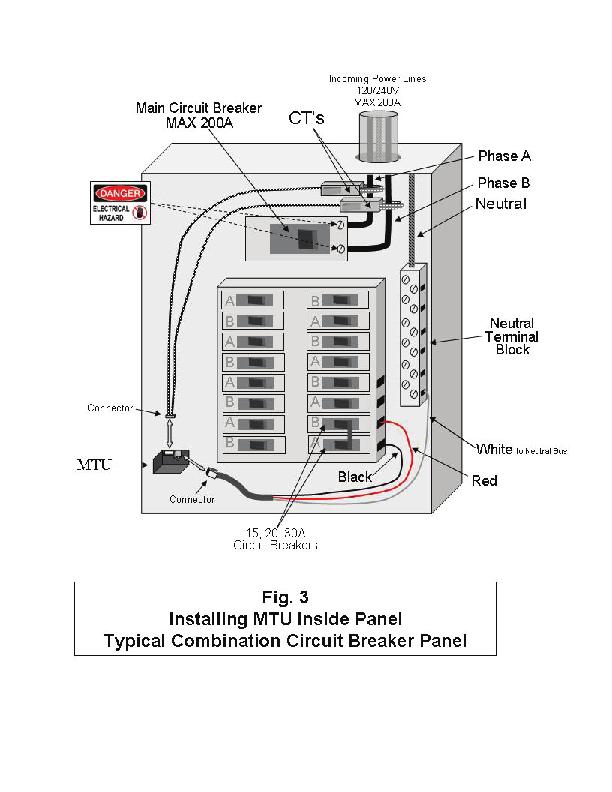
10 Page 10 Quick Start Installation STEP 1 - INSTALLING THE POWER CABLE AND MEA- SURING TRANSMITTING UNIT (MTU). (Refer to FIG 3) TURN OFF ALL POWER TO THE CIRCUIT BREAKER PANEL BY TURNING OFF THE MAIN BREAKER OR MAIN SWITCH. A) Turn off power. B) Remove circuit breaker panel cover. C) Note the ID Number of the MTU as shown on the label. It consists of six digits in the form You will need to know this number to connect the MTU to the Gateway Network. D) Connect the black and red wires from the MTU power cord to a spare 15,20 or 30 Amp two-pole circuit breaker in the panel. E) Note that the black and red wires must create a 240V circuit. They cannot be connected to circuit breakers on the same phase. If there is no spare circuit breaker, the black/red wires can be attached to any 15, 20 or 30 Amp 2-pole cir-cuit breaker in the panel, provided that the circuit breaker is approved for 2 conductors (most are) and this is acceptable to the authority having jurisdiction in the installation location (it is generally acceptable); If a 2-pole circuit breaker is not available, then use an approved handle-tie to create one. F) Connect the white wire from the MTU to the neutral bus on the panel. G) Do not connect the Power Cable to the MTU until you have the CTs connected (see below) STEP 2 - INSTALLING AND CONNECTING THE CURRENT TRANS- FORMERS (CTs) A) CAUTION IF THIS IS A COMBINATION PANEL, THE LUGS ON THE PRIMARY SIDE OF THE MAIN BREAKER ARE PROBABLY STILL HOT. B) The CTs must be installed with the red polarity dots either both facing towards the main breaker, or both away from the main breaker to maintain the correct polarity. If both CTs are not installed in this manner, the readings will be wrong. Note: Do not install the CT over the neutral (N) (grounded) conductor. Energy, Inc Pacific Street Charleston, South Carolina (843)
 The CTs should be installed on the secondary side of the main switch or main circuit breaker, however, if this is not possible, such as in the case of a combination breaker panel, then")
11 Page 11 C) Install one CT over each incoming power line A or B, by pressing on the handle to open the split-core then clipping it over the power line as shown below. Press Here D) The CTs should be installed on the secondary side of the main switch or main circuit breaker, however, if this is not possible, such as in the case of a combination breaker panel, then install on the primary side of the main breaker. E) Make sure the thumb-squeeze split core CTs clamp tightly. (The CTs should be loose-fitting around the wires). F) Connect the CTs and Power Cable to the MTU by plugging the plastic mating connectors together. Note: The connectors are polarized and can only be inserted one way do not force. G) Determine the best location to mount the MTU. a. Choose a location where it will not interfere with existing equipment or wiring. b. The MTU may be attached using double-sided tape (if allowed in your jurisdiction), or with sheet metal or machine screws. H) Arrange and tie-wrap all wiring in a neat and tidy manner. I) Turn the power back on. The MTU will blink approximately 10 times when power is first applied. After this, it will blink when transmitting or receiving data. Do not close the electrical panel until you have completed the installation of the Gateway and verified that correct data is being received from the MTU. If, after the entire system is setup, and the energy being displayed seems very low, or incorrect, try reversing one of the CTs (either one of them). Close the Electrical Panel only after you have confirmed the correct operation of TED, Step 3 Refer to Quick Start Guide for detailed instructions on installing the Gateway and Display Devices, setup and operation of the TED Energy Management System.
.")
12 Page 12 Solar, Wind or Auxiliary Generator Installation Addendum Installing the Solar/Wind, or Auxiliary Generator components ( Solar for short) needs to be completed after the installation instructions have been followed for the installation of MTU 1 (beginning on page 6 of this Instruction Guide). ` Assuming that you have successfully installed MTU 1 as detailed above, it is time to connect MTU 2 to your Solar system. While there are many different variations in Solar connections, we are presenting the installation of MTU 2 in the most common scenario. Solar panels connect to an inverter which changes DC to AC. In most cases it will be 120/240V. The connection can tie into the main switch/circuit Breaker, a transfer switch, a junction box, a splitter box, etc. It really doesn t make any difference. In the case of an auxiliary generator, it will likely tie into a transfer switch because generally speaking, a generator is not run in parallel with the utility. (You will use both CTs if 240v...otherwise, if it is 120V, you only use one CT). In the following drawing, the MTU/CTs are connected similarly as you did connecting MTU 1. If possible, both MTUs should be powered from the panel. This will give the cleanest Power Line Carrier signal. (Try NOT to power the MTU from the inverter, as there will be a lot of line noise that could interfere with the signal).
 766-9800 (800) 959-5833 www.theenergydetective.")
13 Page Pacific Street Charleston, South Carolina (843) (800)
N O T I C E - I M P O R T A N T
 I n s t a l l a t i o n a n d O p e r a t i o n s M a n u a l Page 2 N O T I C E - I M P O R T A N T T E D M O D E L 1 0 0 0 O P E R AT I O N A L L I M I TAT I O N S TED Model 1000 is only suitable for
The Energy Detective
 The Energy Detective ABOUT ENERGY, INC. Energy, Inc. manufactures the product line of TED The Energy Detective, the market leader in electricity monitors. It has been proven that real-time energy feedback
Warning. 1. Have the installation done by a qualified professional, according to local electrical codes. 1. It may not cause harmful interference,
 Solar Install Guide Warning Legal Sense is connected to dangerous voltages. Improper use or installation can be dangerous or even fatal. Please make sure to follow these guidelines: This equipment has
Warning. 1. Have the installation done by a qualified professional, according to local electrical codes. 1. It may not cause harmful interference,
 Warning Legal Sense is connected to dangerous voltages. Improper use or installation can be dangerous or even fatal. Please make sure to follow these guidelines: This equipment has been tested and found
Installation Instructions: Read these instructions in its entirety before performing any installation work.
 WIR-TRAN Rated for use on 110/120VAC 60Hz applications Installation Instructions: Read these instructions in its entirety before performing any installation work. FOR USE WITH POOL AND SPA PRODUCTS ETL
Product Overview. Product Identification. Amps One CT Two CTs Three CTs
 AH06 (optional mounting bracket for small, medium, and large CTs) DANGER HAZARD OF ELECTRIC SHOCK, EXPLOSION, OR ARC FLASH Follow safe electrical work practices. See NFPA 70E in the USA, or applicable
CP-250E-60/72-208/240-MC4 Microinverter with Modular Trunk Cable
 CP-250E-60/72-208/240-MC4 Microinverter with Modular Trunk Cable Chilicon Power Aug 2016 1 CONTENTS CP-250E Microinverter System... 3 The CP-100 Cortex Gateway... 3 Important Safety Information... 4 Inverter
TED 5000 USER MANUAL
 TED 5000 USER MANUAL The Energy Detective (TED) is an accurate electricity monitor that provides real-time feedback on electricity usage. TED will lower utility bills, reduce electric waste, and save the
Owner's/Installation Manual
 Owner's/Installation Manual Power Management Module (PMM) and Starter Kit NOTE: The starter kit must be purchased and installed prior to individual PMM usage. Model Numbers: 00686-0 PMM 00699-0 PMM WITH
Rated for use on 110/120VAC 60Hz and 220/240VAC 60Hz applications
 WPC2-XXXX-T Rated for use on 110/120VAC 60Hz and 220/240VAC 60Hz applications Installation Instructions: Read these instructions in their entirety before performing any installation work. FOR USE WITH
Rated for use on 110/120VAC 60Hz and 220/240VAC 60Hz applications
 WPC1-XXXX-T Rated for use on 110/120VAC 60Hz and 220/240VAC 60Hz applications Installation Instructions: Read these instructions in their entirety before performing any installation work. FOR USE WITH
Installation Instructions: Read these instructions in its entirety before performing any installation work.
 WIR-TRAN Rated for use on 110/120VAC 60Hz applications Installation Instructions: Read these instructions in its entirety before performing any installation work. FOR USE WITH POOL AND SPA PRODUCTS ETL
Installation Guide Smart-UPS On-Line SRT1000/SRT1500 XLA Tower/Rack-Mount
 Installation Guide Smart-UPS On-Line SRT1000/SRT1500 XLA Tower/Rack-Mount Important Safety Messages Read the instructions carefully to become familiar with the equipment before attempting to install, operate,
Installing Power Components
 This chapter provides instructions on how to install and reinstall power components in the Cisco NCS 4016 chassis. It also covers connecting and disconnecting power and powering on the chassis. The Cisco
- Wiring Brochure Zone Manager 335
 - Wiring Brochure W 335 12/08 1 Information Brochure Choose controls to match application 2 Application Brochure Design your mechanical applications Rough-in Wiring Rough-in wiring instructions 3 4 Wiring
Rental Industry Safety Tester Safe Check 5s
 Rental Industry Safety Tester Safe Check 5s Feb 2006 2006 Clare Instruments Inc. Issue 2.0 Firmware Version : 1.2a Limited Warranty & Limitation of Liability Clare Instruments Inc, guarantees this product
High Frequency SineWave Guardian TM
 High Frequency SineWave Guardian TM 380V 480V INSTALLATION GUIDE FORM: SHF-IG-E REL. January 2018 REV. 002 2018 MTE Corporation High Voltage! Only a qualified electrician can carry out the electrical installation
PowerLogic High Density Metering System 4-Meter Enclosure Installation Guide
 PowerLogic High Density Metering System 4-Meter Enclosure Installation Guide 7002-0289-00 Instruction Bulletin HAZARD CATEGORIES AND SPECIAL SYMBOLS Read these instructions carefully and look at the equipment
Users Manual. Defender 1 8.0KW to 14.0KW Online Emergency Lighting Inverter. Technical Manual # Revision B
 Users Manual Defender 1 8.0KW to 14.0KW Online Lighting Inverter Technical Manual #018-0102-01 Revision B Phone: 1.877.DSPM.POWER 1.877.377.6769 Fax: 909.930.3335 Website: www.dspmanufacturing.com E-Mail:
CP /240-MC4 User Manual
 CP-250-60-208/240-MC4 User Manual Chilicon Power LLC Dec 2015 1 CONTENTS Important Safety Instructions... 3 Safety Instructions... 3 CP-250 Microinverter System Introduction... 4 Inverter Label Information...
Users Manual. Cobra Plus Stand-By Emergency Lighting Inverter. Technical Manual # Revision B
 Users Manual Cobra Plus Stand-By Lighting Inverter Technical Manual #018-0110-01 Revision B Phone: 1.877.DSPM.POWER 1.877.377.6769 Fax: 909.930.3335 Website: www.dspmanufacturing.com E-Mail: techsupport@dspmanufacturing.com
Technical Manual. DLM Module. This manual should remain with the unit.
 Technical Manual DLM Module This manual should remain with the unit. Safety Rules SAVE THESE INSTRUCTIONS! Read the following information carefully before attempting to install, operate or service this
Supply-Side PV Connections
 Perspectives on PV Supply-Side PV Connections by John Wiles Plan reviewers and inspectors throughout the country are seeing increasing numbers of supply-side connected utility interactive photovoltaic
Rated for use on 110/120VAC 60Hz and 220/240VAC 60Hz applications
 WPC-1 Rated for use on 110/120VAC 60Hz and 220/240VAC 60Hz applications Installation Instructions: Read these instructions in their entirety before performing any installation work. FOR USE WITH POOL AND
Elegance Electrician s Installation Guide
 Elegance Electrician s Installation Guide CentraLite Systems, Inc. 6420 Wall St. Mobile, AL 36695 Phone: 877-466-5483 Fax: 251-607-9119 2003-2005 CentraLite Systems, Inc. Revised 10/20/2005 ELECTRICIAN
Powerware Vdc Extended Battery Cabinet User s Guide.
 Powerware 9125 48 Vdc Extended Battery Cabinet User s Guide www.powerware.com FCC Part 15 Class A EMC Statements NOTE This equipment has been tested and found to comply with the limits for a Class A digital
Instruction Book for. ContouR ElECtRol
 Instruction Book for ContouR ElECtRol IMPORTANT SAFETY INSTRUCTIONS When using your video equipment, basic safety precautions should always be followed, including the following: 1. Read and understand
Battery Chargers Sealed or Valve Regulated Lead Acid Batteries Model: PSC A
 Battery Chargers Sealed or Valve Regulated Lead Acid Batteries Model: PSC-124000A OPERATING PROCEDURES AND SAFETY INSTRUCTIONS CAUTION: TO PREVENT THE RISK OF ELECTRIC SHOCK, DO NOT REMOVE COVER NO USER
- Wiring Brochure Zone Manager 336
 - Wiring Brochure W 336 12/08 1 Information Brochure Choose controls to match application Application Brochure Design your mechanical applications 2 3 Rough-in Wiring Rough-in 4 Wiring Brochure Wiring
Battery Chargers Sealed or Valve Regulated Lead Acid Batteries Models: PSC A AND PSC A
 Battery Chargers Sealed or Valve Regulated Lead Acid Batteries Models: PSC-122000A AND PSC-241000A Operating Instructions WARNING CONCERNING THE REMOVAL OF COVER: CAUTION: TO PREVENT THE RISK OF ELECTRIC
Sunwize Water Pumping Kit Quick Start
 Document # 310014 Sunwize Water Pumping Kit Quick Start The purpose of this guide is to assist you in setting up your system quickly and efficiently. Important! Prior to field installation Determine and
Battery Chargers Sealed or Valve Regulated Lead Acid Batteries Model: PSC AP
 Battery Chargers Sealed or Valve Regulated Lead Acid Batteries Model: PSC-124000AP OPERATING PROCEDURES AND SAFETY INSTRUCTIONS CAUTION: TO PREVENT THE RISK OF ELECTRIC SHOCK, DO NOT REMOVE COVER NO USER
INSTALLATION MANUAL ELECTRIC DOUBLE OVEN RANGE
 ENGLISH ESPAÑOL INSTALLATION MANUAL ELECTRIC DOUBLE OVEN RANGE Please read these instructions thoroughly before installing and operating the range. LDE3019ST LDE3017ST LDE3017SB LDE3017SW LDE3015ST LDE3015SB
Models beginning with MO, MK, 7B, 6S, 6F or 5B. Product Description. Technical Specifications. Installation Instructions.
 Models beginning with MO, MK, 7B, 6S, 6F or 5B The Mini Meter Product Description Technical Specifications Installation Instructions February 28 th, 2013 1. Product Description...2 1.1 General Description...2
dv Sentry TM 208V 600V INSTALLATION GUIDE Quick Reference ❶ How to Install Pages 6 14 ❷ Startup/Troubleshooting Pages WARNING
 dv Sentry TM 208V 600V INSTALLATION GUIDE FORM: DVS-IG-E REL. January 2018 REV. 003 2018 MTE Corporation High Voltage! Only a qualified electrician can carry out the electrical installation of this filter.
Asymmetrical Installation Instructions. Components: i2cove Asymmetrical LED Light Fixtures. 12 [305mm] [918mm] 48.
![Asymmetrical Installation Instructions. Components: i2cove Asymmetrical LED Light Fixtures. 12 [305mm] [918mm] 48.](/thumbs/77/74625192.jpg "Asymmetrical Installation Instructions. Components: i2cove Asymmetrical LED Light Fixtures. 12 [305mm] [918mm] 48.") support@i2systems.com www.i2systems.com Electrical Specifications PARAMETER Input Power VALUE 8 Watts* / Ft Input Voltage 120-277V AC, 50/60 Hz Max. Fixture Run Length LED Color (CCT) 8 Watts: 120VAC:
support@i2systems.com www.i2systems.com Electrical Specifications PARAMETER Input Power VALUE 8 Watts* / Ft Input Voltage 120-277V AC, 50/60 Hz Max. Fixture Run Length LED Color (CCT) 8 Watts: 120VAC:
innovations in battery charging
 innovations in battery charging AutomaticBatteryCharger forsealed or Valve Regulated Lead-Acid Batteries Model HPX-60 Series OperatingInstructions WARNING CONCERNING THE REMOVAL OF COVER: CAUTION: TO PREVENT
7.5 FT PRE-LIT ENGLEWOOD PINE TREE
 ITEM #0243778 7.5 FT PRE-LIT ENGLEWOOD PINE TREE Holiday Living & Design is a registered trademark of LF, LLC. All Rights Reserved. MODEL #W14L030 Español p. 11 ATTACH YOUR RECEIPT HERE Serial Number Purchase
UBC Technical Guidelines Section Edition Commissioning of Electrical Systems Page 1 of 5
 Page 1 of 5 1.0 GENERAL 1.1 Coordination Requirements.1 UBC Building Operations Electrical Technical Support.2 UBC Energy & Water Services 2.0 REQUIREMENTS FOR COMMISSIONING AND TESTING 2.1 Testing.1 Unit
INSTRUCTION BOOK FOR. Cosmopolitan Electrol For Sizes Up To 9' x 12'
 INSTRUCTION BOOK FOR Cosmopolitan Electrol For Sizes To 9' x 12' Important Safety Instructions When using your video equipment, basic safety precautions should always be followed, including the following:
SineWave Guardian TM 380V 600V INSTALLATION GUIDE. Quick Reference. ❶ How to Install Pages 6 17 ❷ Startup/Troubleshooting Pages WARNING
 SineWave Guardian TM 380V 600V INSTALLATION GUIDE FORM: SWG-IG-E REL. October 2018 REV. 003 2018 MTE Corporation High Voltage! Only a qualified electrician can carry out the electrical installation of
SOS SERIES SOS1 SOS2. Spares On Site Battery Cabinet Installation Guide rEV3
 Atlantic Battery Systems 1065 Market Street Paterson, NJ 07513 Phone: (800) 875-0073 Fax: (973) 523-2344 sales@atbatsys.com www.atbatsys.com SOS1 SOS2 SOS SERIES Spares On Site Battery Cabinet Installation
Assessing a Site for Installation of Consumption Monitoring
 TECHNICAL BRIEF Assessing a Site for Installation of Consumption Monitoring About the Enphase Envoy-S Metered The Enphase Envoy-S Metered communications gateway enables performance monitoring and remote
The Da-Lite Difference.
 The Da-Lite Difference. Instruction Book for Cosmopolitan Electrol For Sizes Up To 9'x12' DA-LITE SCREEN COMPANY, INC. 3100 North Detroit Street Post Office Box 137 Warsaw, Indiana 46581-0137 Phone: 574-267-8101
Uninterruptible power supply Supply MEg101.4
 Uninterruptible power supply Supply MEg101.4 MEgA Měřící Energetické Aparáty, a.s. 664 31 Česká 390 Czech Republic Uninterruptible power supply Supply MEg101.4 Uninterruptible power supply MEg101.4 1/
INSTALLATION AND OPERATING INSTRUCTIONS OF THE INTERNATIONAL ISOBOX SERIES ISOLATION TRANSFORMERS.
 INSTALLATION AND OPERATING INSTRUCTIONS OF THE INTERNATIONAL ISOBOX SERIES ISOLATION TRANSFORMERS. Before installing and/or using this product, please check for any visual damage of the enclosure, power
BLUE 3 INSTALLATION GUIDE
 BLUE 3 INSTALLATION GUIDE CATCH Power BLUE 3 Installation manual - Page 1 IMPORTANT This product must be installed by a licensed electrician. This product must be installed according to the AS3000 Australian
ET-PWR-END-KIT Installation Instructions (part #JSR00)
") (part #JSR00) Please read and save these instructions. Read carefully before attempting to assemble, install, operate or maintain the product described. Protect yourself and others by observing all safety
(part #JSR00) Please read and save these instructions. Read carefully before attempting to assemble, install, operate or maintain the product described. Protect yourself and others by observing all safety
PowerPlex 40V MAX Standard Battery Pack/Charger
 Form No. 3417-974 Rev C PowerPlex 40V MAX Standard Battery Pack/Charger Model No. 88540 Serial No. 318000001 and Up Model No. 88541 Serial No. 318000001 and Up Model No. 88542 Serial No. 318000001 and
INSTALLATION INSTRUCTION W Track Recessed 120V Flangeless
 W Track Recessed 120V Flangeless WT4-RTL, WT8-RTL, WT12-RTL SAFETY INSTRUCTION Read all of these instructions before installing the track system. Turn off power at main switch before installing or modifying
Infinity 1U 19 Converter Shelf Models: J L224-48V to +24V, L V to -48V
 GE Critical Power Quick Start Guide Infinity 1U 19 Converter Shelf Models: J5964803 L224-48V to +24V, L225 +24V to -48V Edge Controller example Outputs RTNs Inputs RTNs Refer to Infinity Converter Brochure
M T E C o r p o r a t i o n. dv/dt Filter. Series A VAC USER MANUAL PART NO. INSTR REL MTE Corporation
 M T E C o r p o r a t i o n dv/dt Filter Series A 440-600 VAC USER MANUAL PART NO. INSTR - 019 REL. 041119 2004 MTE Corporation IMPORTANT USER INFORMATION NOTICE The MTE Corporation dv/dt Filter is designed
INTERCONNECTION STANDARDS FOR PARALLEL OPERATION OF SMALL-SIZE GENERATING FACILITIES KILOWATTS IN THE STATE OF NEW JERSEY
 INTERCONNECTION STANDARDS FOR PARALLEL OPERATION OF SMALL-SIZE GENERATING FACILITIES 10-100 KILOWATTS IN THE STATE OF NEW JERSEY January 1, 2005 Rockland Electric Company 390 West Route 59 Spring Valley,
Definitions. Scope. Customer Generation Interconnection Requirements
 Updated 02/1 Page 1 Scope The purpose of this document is to describe Idaho Power s requirements for the installation and testing of Customer Generation acilities that are interconnected with Idaho Power
INSTALLATION AND OPERATING INSTRUCTIONS OF THE INTERNATIONAL ISOBOX SERIES ISOLATION TRANSFORMERS.
 INSTALLATION AND OPERATING INSTRUCTIONS OF THE INTERNATIONAL ISOBOX SERIES ISOLATION TRANSFORMERS. Before installing and/or using this product, please check for any visual damage of the enclosure, power
INSTALLATION GUIDE AND USER MANUAL
 Electric Vehicle Charging Station INSTALLATION GUIDE AND USER MANUAL Model: 30A EVoCharge EVSE Model Number: EV072-300-001A Product Safety Certification: UL and cul Listed Description: SAE J1772 AC Level
i-energy i-micro inverter GT260
 i-energy i-micro inverter GT260 This installation guide contains important instructions on safety matters and the installation of the i-energy i-micro inverter GT260. Please read this guide carefully and
OBAE, OBAEXU, ON BOARD Battery Chargers
 C O R P O R A T IO N O P E R A T I N G I N S T R U C T I O N S OBAE, OBAEXU, ON BOARD Battery Chargers INTRODUCTION: The OBAE line of chargers are designed for the permanent installation on battery powered
INSTALLATION GUIDE AND USER MANUAL
 Electric Vehicle Charging Station INSTALLATION GUIDE AND USER MANUAL SAE J1772 AC Level 2 EVSE Model: 30A EVoCharge EVSE Wall Mount P/N: EV072-300-001A Version 2.0 IMPORTANT Read this manual thoroughly
Electric. PN April Series Electric Oven
 Electric PN April 2013 Series Electric Oven E NOTICE: This Owner s Operating and Installation Manual should be given to the user. The operator of the oven should be familiar with the operation of the oven.
Owner's Manual 600 and 800 Amp RTS Automatic Transfer Switch
 Owner's Manual 600 and 800 Amp RTS Automatic Transfer Switch Safety Rules SAVE THESE INSTRUCTIONS! Read the following information carefully before attempting to install, operate or service this equipment.
Installer Guide smart connect
 Installer Guide smart connect TM 7490 Wireless Remote Outdoor Sensor Please read all instructions before proceeding. The wireless remote outdoor sensor monitors temperature at a remote outdoor location
nual k Voltage Stabilizer N) manual New Brunswick Voltage Stabilizer Operating manual
 manual New Brunswick Voltage Stabilizer Operating manual") nual k Voltage Stabilizer N) manual New Brunswick Voltage Stabilizer Operating manual Copyright Copyright 2014 Eppendorf AG, Germany. No part of this publication may be reproduced without the prior permission
nual k Voltage Stabilizer N) manual New Brunswick Voltage Stabilizer Operating manual Copyright Copyright 2014 Eppendorf AG, Germany. No part of this publication may be reproduced without the prior permission
READ AND FOLLOW ALL SAFETY INSTRUCTIONS! SAVE THESE INSTRUCTIONS AND DELIVER TO OWNER AFTER INSTALLATION
 READ AND FOLLOW ALL SAFETY INSTRUCTIONS! SAVE THESE INSTRUCTIONS AND DELIVER TO OWNER AFTER INSTALLATION To reduce the risk of death, personal injury or property damage from fire, electric shock, falling
Owner s Manual. For Automatic Transfer Switch. 100 Amp. Model Number RTG16EZA3 MODEL NUMBER: SERIAL NUMBER: DATE PURCHASED:
 Owner s Manual For Automatic Transfer Switch 100 Amp Model Number RTG16EZA3 MODEL NUMBER: SERIAL NUMBER: DATE PURCHASED: Register your Generac product at: WWW.GENERAC.COM 888-436-3722 Para español, visita:
EVoInnovate EVSE Model Numbers: EVO & EVO User Manual & Installation Guide. Revision 1.0
 EVoInnovate EVSE Model Numbers: EVO32-300-001 & EVO32-300-002 User Manual & Installation Guide Revision 1.0 IMPORTANT SAFETY INSTRUCTIONS This document contains instructions and warnings that must be followed
LED IMPORTANT SAFETY INSTRUCTIONS
 LED IMPORTANT SAFETY INSTRUCTIONS READ AND FOLLOW ALL SAFETY INSTRUCTIONS! SAVE THESE INSTRUCTIONS AND DELIVER TO OWNER AFTER INSTALLATION To reduce the risk of death, personal injury or property damage
PSX-240 Enclosed Autotransformer Installation Manual
 PSX-240 Enclosed Autotransformer Installation Manual IMPORTANT SAFETY INSTRUCTIONS SAVE THESE INSTRUCTIONS! This manual contains important instructions for the OutBack PSX-240 Autotransformer. All of the
SAVE THESE INSTRUCTIONS
 READ AND FOLLOW ALL SAFETY INSTRUCTIONS! SAVE THESE INSTRUCTIONS AND DELIVER TO OWNER AFTER INSTALLATION IMPORTANT SAFEGUARDS! When using electrical equipment, basic safety precautions should always be
METERING REQUIREMENTS
 METERING REQUIREMENTS KUA will not accept a non-securable service trough entrance. That is, all enclosed conductors prior to the meter (line side) will be securable by and accessible to KUA personnel only.
HANGKAI GROUP HOYMILES MICRO-INVERTER MI-250
 HANGKAI GROUP HOYMILES MICRO-INVERTER MI-250 TECHNICAL MANUAL CONTENTS INTRODUCTION... 3 SAFETY... 4 SYMBOL ILLUSTRATION... 4 INSTALLATION WARNINGS... 6 PREPARE FOR INSTALLING... 7 TRANSPORT AND INSPECT...
REFERENCE MANUAL FORM: MX-TRM-E REL REV MTE
 Matrix APAX 380V-415V 50Hz TECHNICAL REFERENCE MANUAL FORM: MX-TRM-E REL. September 2014 REV. 002 2014 MTE Corporation WARNING High Voltage! Only a qualified electrician can carry out the electrical installation
GS-IOB-120/240VAC. Input/Output/Bypass Assembly. Installation Instructions. Purpose. Scope. Requirements. Grounding Instructions
 GS-IOB-120/240VAC Input/Output/Bypass Assembly Installation Instructions Purpose This document provides information on how to install the Input/Output/Bypass Assembly needed for a 120/240 Vac configuration
RT Series Step Down Transformer for RT Series UPS 6-10kVA UL Input Vac Output Vac User Guide
 RT Series Step Down Transformer for RT Series UPS 6-10kVA UL Input 208-240 Vac Output 208-120 Vac User Guide UNLESS SPECIFICALLY AGREED TO IN WRITING, SELLER (A) MAKES NO WARRANTY AS TO THE ACCURACY, SUFFICIENCY
3 year warranty. (1) Treo Micro fiberglass, gunite fitting, 3/4 PVC. FLED-TM-W-PK10 (10) Treo Micros (WHITE) 80 NEW! Treo Micro fitting adapter
 Treo Micro fiberglass, gunite fitting, 3/4 PVC. FLED-TM-W-PK10 (10) Treo Micros (WHITE) 80 NEW! Treo Micro fitting adapter") pool lighting The Treo Micro LED light is 12VAC, 2 Watt LED underwater light designed for accent Available in lengths of 30, 50, 80', 150 50,000 hour lamp life No Earth bonding required White or color
pool lighting The Treo Micro LED light is 12VAC, 2 Watt LED underwater light designed for accent Available in lengths of 30, 50, 80', 150 50,000 hour lamp life No Earth bonding required White or color
PF Guard Power Factor Capacitor Bank Installation, Operation, and Maintenance Manual
 PF Guard Power Factor Capacitor Bank Installation, Operation, and Maintenance Manual No part of this publication may be reproduced, stored in a retrieval system, or transmitted in any form or by any means,
ONE TOUCH CONTROL BOX
 ONE TOUCH CONTROL BOX CONVERSION KIT INSTRUCTIONS REMOVAL, INSTALLATION, OPERATION, AND REMOTE CONTROL PROGRAMMING THUNDERSTONE PART #101322 REVISION A JULY 14 TH 2016 2 P a g e INSTALLING THE THUNDER
Electric Vehicle Charging Station
 EVoReel Electric Vehicle Charging Station INSTALLATION GUIDE AND USER MANUAL Model: Dual Output Pedestal Mount 30A EVoReel EVSE Model Numbers: With Basic EVSE: EV072-400-002A; With Intelligent ievse: EV072-410-002A;
The Da-Lite Difference.
 The Da-Lite Difference. Instruction Book for Large Advantage Electrol DA-LITE SCREEN COMPANY, INC. 3100 North Detroit Street Post Office Box 137 Warsaw, Indiana 46581-0137 Phone: 574-267-8101 800-622-3737
Using OutBack Inverters for 3-Phase 480V Applications
 Using OutBack Inverters for 3-Phase 480V Applications Introduction This application note will discuss how to adapt OutBack Power 230V single phase inverters for 60 Hz 480V three-phase applications using
Matrix APAX. 380V-415V 50Hz TECHNICAL REFERENCE MANUAL
 Matrix APAX 380V-415V 50Hz TECHNICAL REFERENCE MANUAL WARNING High Voltage! Only a qualified electrician can carry out the electrical installation of this filter. Quick Reference ❶ Performance Data Pages
Connecting to DC Power
 APPENDIXC This appendix describes how to make DC power connections to the Catalyst 3750G-12S-SD switch. See the Installing the Switch section on page 2-11 for instructions on installing the switch. To
B BASIC HEAT TREATMENT CONSOLE
 Maritime Stress PO Box 2898, 30 Estates Road Dartmouth, NS, B2W 4Y2, Canada Toll Free: 1-877-468-1781 Phone: (902) 468-7873 Fax: (902) 468-2304 Website: E-mail: info@maritimestress.com OPERATION MANUAL
Actionpac LNS4. Panel Installation Datasheet. Actionpac LNS4 RELEASE 1.0 JUNE In partnership
 Actionpac LNS4 Panel Installation Datasheet ELECTROSTATIC SENSITIVE DEVICE This product forms part of a life safety system. Failure to correctly store, handle, install and maintain the product will directly
PORTABLE POWER SUPPLY MODEL NUMBER VMS-1 VERSION 1.0
 PORTABLE POWER SUPPLY MODEL NUMBER VMS-1 VERSION 1.0 MM September 21, 2012 TABLE OF CONTENTS Section Number DANGER INTRODUCTION AND TECHNICAL SPECIFICATIONS 1 CONTROL AND METERING DESCRIPTION 2 OPERATION
i400s Calibration Information Introduction
 i400s AC Current Clamp Introduction XWWarning To avoid electric shock or injury, do not perform the performance tests or calibration procedures unless you are qualified to do so. The information provided
FLO Home TM X5 Model. Installation Manual FLO Services Inc. All rights reserved.
 FLO Home TM X5 Model Installation Manual 2016 FLO Services Inc. All rights reserved. v161130:2013 Table of Contents Specifications 3 Safety Instructions 4 Planning your Installation 5 Box Contents 6 Installing
Mini Multimeter with Non-Contact Voltage Detector (NCV)
") Owner s Manual Mini Multimeter with Non-Contact Voltage Detector (NCV) Model No. 82314 CAUTION: Read, understand and follow Safety Rules and Operating Instructions in this manual before using this product.
Owner s Manual Mini Multimeter with Non-Contact Voltage Detector (NCV) Model No. 82314 CAUTION: Read, understand and follow Safety Rules and Operating Instructions in this manual before using this product.
Installation and Operating Instructions SWITCHED NEUTRAL KIT MODEL SNK
 Installation and Operating Instructions SWITCHED NEUTRAL KIT MODEL SNK Warning: The Gen/Tran Switched Neutral Kit should be installed by a professional electrician familiar with electrical wiring and codes,
Owner's Manual. LTS Load Shed Switch. This manual should remain with the unit.
 Owner's Manual LTS Load Shed Switch This manual should remain with the unit. Table of Contents SAFETY RULES SAVE THESE INSTRUCTIONS - This manual contains important instructions that should be followed
Installation Instructions
 265V Subbase Receptacle Accessory Kit For Use With Packaged Terminal Air Conditioner Installation Instructions INTRODUCTION These instructions cover the installation of the 265V Subbase Receptacle Accessory
Owner's Manual. LTS Load Shed Switch. This manual should remain with the unit.
 Owner's Manual LTS Load Shed Switch This manual should remain with the unit. Table of Contents Safety Rules... Inside Front Cover General Information... 2 1.1 Introduction... 2 1.2 Equipment Description...
Dominion PX. Quick Setup Guide. Before You Begin. Mounting Zero U Models Using L-Bracket. Zero U Size. 1U and 2U Size
 Dominion PX Quick Setup Guide Thank you for purchasing the Dominion PX intelligent power distribution unit (PDU). The intended use of the Raritan Dominion PX is distribution of power to information technology
Service Entrance Methods
 Service Section Typical switchboards consist of a service section, also referred to as the main section, and one or more distribution sections. The service section can be fed directly from the utility
AIS and 40 kva 400 V. Site Preparation and Installation Manual
 AIS 3100 20 and 40 kva 400 V Site Preparation and Installation Manual www.apc.com AIS 3100 20 and 40 kva 400 V Site Preparation and Installation Manual www.apc.com IMPORTANT SAFETY INSTRUCTIONS SAVE THESE
1718 W. Fullerton Ave Chicago, IL Tel: Fax:
 206 Edge Lighting. All Rights Reserved. Installation Instructions for Nova Power Suspension Up/Down - Center Feed Glide Up/Down - Center Feed IMPORTANT INFORMATION - This product is suitable for indoor
Apollo Solar Inverter Switchgear Module Installation Manual Rev 1.2 Page 1
 Apollo Solar Inverter Switchgear Module Installation Manual Rev 1.2 Page 1 Model/Configuration: ISM 120/240, ISM 120/240-T80, ISM 120, ISM 120-T80 The Apollo Solar Inverter Switchgear Module (ISM) meets
O & M Manual for the EATON Generator Ready Loadcenter
 O & M Manual for the EATON Instructional Booklet New Information Description Page 1. Introduction............................... 2 2. Receiving, Handling, and Storage................ 4 3. Equipment Description........................
INDUSTRY WIDE LABOR-MANAGEMENT SAFETY COMMITTEE
 INDUSTRY WIDE LABOR-MANAGEMENT SAFETY COMMITTEE SAFETY BULLETIN #23 GUIDELINES FOR WORKING WITH LIGHTING SYSTEMS AND OTHER ELECTRICAL EQUIPMENT All electrical systems and electrically energized equipment
The Da-Lite Difference.
 The Da-Lite Difference. Instruction Book for tensioned Advantage Electrol DA-LITE SCREEN COMPANY, INC. 3100 North Detroit Street Post Office Box 137 Warsaw, Indiana 46581-0137 Phone: 574-267-8101 800-622-3737