Legacy Titanium HF MULTI Battery Charger Owner's Manual
|
|
|
- Baldric Montgomery
- 6 years ago
- Views:
Transcription

1 MODEL: LM3 Legacy Titanium HF MULTI Battery Charger Owner's Manual To automatically be connected to your closest Service Center, call us toll-free at DOUGLAS ( ) Or, visit us at: Model: S/N: AC Input Voltage I.B Rev B Installed by Date IMPORTANT Read and understand your user s manual before installing, operating, or servicing this product. DO NOT DESTROY THIS BOOK
2 TABLE OF CONTENTS AC Line Voltage Letter Codes... 2 Specialty Charger Options List... 2 Important Safety Instructions..3 Technical Information... 4 Part Number... 4 Serial Number... 4 Battery Type... 4 Ampere-Hours... 4 Cells... 4 Input AC Volts... 4 Input AC Amps... 4 Hz... 5 Phase... 5 DC Volts... 5 Rated DC Amps... 5 Installation.6 Location... 6 Electrical Connections... 6 On three phase units... 6 Connecting Input Power... 6 AC Connection... 6 Plug Polarity... 6 Grounding the Charger... 6 Description of Operation...7 General... 7 Beginning the Charge... 7 Charging... 7 AC Power Fail... 7 Series Charging... 7 Glossary.8 Charging Coefficient... 8 Charging Profile... 8 Cold Storage... 8 Equalization Charging... 8 IGBT... 8 Ionic Profile... 8 Power Diodes... 8 Refresh Charging... 8 Operating Instructions 9 Charger Configuration and Setup... 9 Factory Configuration... 9 Changing Configuration... 9 Factory Settings Changing Settings Charger Control Panel...11 Charging 12 Introduction Normal Charging Delayed Start Initiating Charging Equalization Charging Manual Initiation Automatic Initiation Refresh Charging End of Charge Data Storage Messages during Charging Messages for Faults Other Messages Maintenance & Service..14 Module Replacement Parts Module Component Locations Cabinet Replacement Parts Output Cable Replacement Schematic Cabinet and Base Dimensions...20 Complete Cabinet Appearance...21 Maintenance Log
3 AC LINE VOLTAGE LETTER CODES The following table describes the code letters to be used in new charger part numbers to indicate the AC line voltage(s) and AC line frequency at which the charger can be operated. Code Letter Voltage (Volts rms.) Line Frequency (Hz) Comments Y /60 Use only for special designs; three phase. SPECIALTY CHARGER OPTIONS LIST Suffix Description 2
4 IMPORTANT SAFETY INSTRUCTIONS 1. This manual contains important safety and operating instructions. Before using the battery charger, read all instructions, cautions, and warnings on the battery charger, the battery, and the product using the battery. 2. This charger has been designed to only charge flooded, lead-acid batteries. Read and understand all setup and operating instructions before using the battery charger to prevent damage to the battery and to the charger. 3. Do not touch non-insulated parts of the output connector or the battery terminals to prevent electrical shock. 4. During charge, batteries produce hydrogen gas which can explode if ignited. Never smoke, use an open flame, or create sparks in the vicinity of the battery. Ventilate well when the battery is in an enclosed space. 5. Do not connect or disconnect the battery plug while the charger is on. Doing so will cause arcing and burning of the connector resulting in charger damage or battery explosion. 6. Lead-acid batteries contain sulfuric acid which causes burns. Do not get in eyes, on skin, or on clothing. In cases of contact with eyes, flush immediately with clean water for 15 minutes. Seek medical attention immediately. 7. Only factory qualified personnel can service this equipment. De-energize all AC and DC power connections before servicing the charger. 8. The charger is not for outdoor use. 9. Do not expose the charger to moisture. Operating conditions should be 0º to 104º F; 0 to 70% relative humidity. 10. Do not operate the charger if it has been dropped, received a sharp hit, or otherwise damaged in any way. 11. For continued protection and to reduce the risk of fire, install chargers on a floor of non-combustible material such as stone, brick, or grounded metal. WARNING: The shipping pallet must be removed for proper and safe operation. INSTRUCTIONS DE SÉCURITÉ IMPORTANTES 1. Ce manuel contient des informations et des consignes importantes pour l emploi et l utilisation du chargeur de batteries industrielles. Avant tout emploi, il est fortement conseillé de lire l ensemble des instructions, recommandations, et avertissements concernant le chargeur et la batterie. 2. Ce chargeur a été conçu pour la charge des batteries industrielles type plomb-acide dite «ouverte». (Il ne peut pas être adapté pour les batteries étanches.) 3. Lisez toutes les condisnes d installation et d utilisation avant d employer le chargeur de batterie pour empêcher des dommages à la batterie et / ou au chargeur. 4. Ne pas être en contact avec les pièces sous-tension non-isolées tels que la prise de charge ou des éléments de sonnexion de la batterie pour empêcher le choc électrique. 5. Pendant la charge, le dégagement d hydrogène rend l emploi de feu strictement interdit «risque d explosion». Ne jamais fumer, employer une flamme nue, ou créez les étincelles à proximité de la batterie. Ventiler suffisamment pour éviter toute condensation de gaz dans un espace restreint. 6. Ne brancher ou débrancher la batterie que si le chargeur est à l arrêt. Faire ainsi risque d endommager la prise de charge pouvant avoir pour conséquence des dommages du chargeur ou l explosion de la batterie. 7. Les batteries d acide au plomb contiennent l acide sulfurique, qui cause des brûlures. Eviter le contact avec les yeux, la peau, ou sur l habillement. Dans le cas de contact avec les yeux, it faut nettayer immédiatement avec de l eau propre pendant 15 minutes et consulter un médecin immédiatement. 8. Seul le personnel qualifié par l usine peut entretenir cet équipement. Pour le service, veuillez contacter la société Douglas ou l un de ces représentant DOUGLAS ( ) 9. Avant toute intervention d entretien ou de réparation il faut s assurer que le chargeur est hors tension et la batterie est déconnectée. 10. Le chargeur n est pas pour un usage extérieur. 11. Ne pas exposer le chargeur à l humidite. Les conditions de fonctionnement devraient être 15 à 40 c; humidité relative de 0 à de 70%. 12. Ne pas mettre en fonctionnement le chargeur s il a reçu un choc mécanique ou tout autre dommage di quel que façon. 13. Pour une protection permanente et pour réduire le risque du feu, installez les chargeurs sur un plancher ou un matériel non-combustible tel qu un mur plein en beton, en brique, ou le acier. 3

5 TECHNICAL INFORMATION The nameplate, located on the outside of the charger, should be used to check this application before installation. Charger Part Number This number specifies in general the characteristics of this particular charger and for this reason it is required in any discussion or correspondence regarding this unit. LMP-CC-AAA(A)VOOOO Model type Phase Number of Cells Ampere-hour (3-4 digits) AC Line Voltage code Option(s) Cabinet Part Number This number specifies in general the characteristics of this particular cabinet and for this reason it is required in any discussion or correspondence regarding this unit. LMP-C#-AAA(A)V# Model type Phase Cabinet capacity Ampere-hour (3-4 digits) Volt code AC Inputs Serial Number This number indicates complete information about the specific charger or cabinet. It must be supplied with the part number on any correspondence or discussion regarding any charger or cabinet. Battery Type The chemical content construction of the battery this unit is designed to charge is given in this part of the nameplate. (L-A = Flooded Lead-Acid) Ampere-Hours The information supplied here is the ampere-hour battery capacity which this unit has been factory adjusted to charge. Charging batteries of ampere-hour capacities not specified here might cause the charger to deviate from the specifications. Cells This portion of the nameplate gives the number of cells this unit will charge. This number must match exactly with any battery connected to the charger output. Input AC Volts The nameplate shows the input voltage accommodated by the charger or cabinet. IMPORTANT: The charger will operate only on nominal line voltages stamped on the nameplate. Failure to select the correct voltage will result in damage to the charger and/or the battery. Input AC Amps The external fusing and/or the line disconnect circuit breaker should be as specified in the National Electrical Code or other local code agencies. (AC fuse values can be found on the decal inside the charger.) 4
6 Hz This gives the frequency in cycles per second of the AC input voltage. Under no conditions operate charger at a different frequency or from a generator with unstable frequency. Phase Number "3" indicates a Three Phase Charger. DC Volts This gives the nominal DC output voltage of the system. Rated DC Amps This is the nominal DC value of current that this unit will deliver to a battery that is 100% discharged. 5
7 INSTALLATION WARNING: The shipping pallet must be removed for proper and safe operation. Location For maximum trouble-free service, choose a location which is free of excess moisture, dust, and corrosive fumes. Also, avoid locations where temperatures are high or where liquids will drip on the charger. Allow six (6) inches of clearance at rear and sides of the charger for air circulation. Do not obstruct the ventilating openings or the space under the charger. NOTE: Ambient temperature at all levels cannot exceed 104 O F / 40 O C Electrical Connections To prevent failure of the charger, be sure it is connected to the correct line voltage. On three phase units Connect each charger as follows: Phase A to L1 (terminal block) Phase B to L2 (terminal block) Phase C to L3 (terminal block) Note: Polarity of phases is not important, i.e., phase A can be connected to L2 or L3 instead of L1. Connecting Input Power WARNING: Make sure the power to the charger is OFF and the battery is disconnected before connecting the input power to the terminals of the charger. Connect the input power to the appropriate terminals, including ground. Follow your local electrical or National Electric Code in making these connections. AC Connection The user must provide suitable branch circuit protection and a disconnect method from the AC power supply to the charger to allow for safe servicing. Plug Polarity The charging cable is connected to the DC output of the charger with the positive lead marked RED. The output polarity of the charger must be strictly observed when connecting to the battery (read warning above). Improper connection will open the DC fuse. Grounding the Charger DANGER: FAILURE TO GROUND THE CHARGER COULD LEAD TO FATAL ELECTRIC SHOCK. Follow National Electric Code for ground wire sizing. Connect a grounding conductor to the lug provided in the horizontal power supply box. This lug is marked as shown: 6
8 DESCRIPTION OF OPERATION GENERAL Legacy Titanium HF MULTI chargers are microprocessor-controlled. The processor calculates the battery s capacity so that the charging profile can be automatically adapted to the battery s actual state over a wide range of capacities. The charging coefficient is maintained absolutely on all types of batteries. Legacy Titanium HF MULTI chargers adapt to the battery s capacity and its discharge level. As a result of our patented charging methodology, our chargers lower energy costs, and extend battery life. Legacy Titanium HF MULTI chargers can easily be set to charge batteries used in cold or freezer storage applications. This battery charger is designed to charge flooded lead-acid storage batteries within the range of the cell and ampere-hour rating as marked on the nameplate. Beginning the Charge When a battery is connected to the charger, the control board senses voltage and after a 1 minute delay, the charger starts charging. Charging Charging current is determined by the battery voltage and capacity. Charging current declines automatically as battery voltage rises during the charge. As the battery charges, the charger display will output various charge parameters including the percentage of battery capacity. AC Power Fail If the AC power fails with a battery connected to the charger during a charge cycle, the charger will reset and start a new charge cycle when power is restored. Parallel Charging In parallel charging, batteries must have an equal number of cells and must match the charger nameplate s ratings. Ampere- Hour rating of charger must be equal to the Ampere-Hour of both batteries combined. Theoretically, charging current is equally divided between both batteries provided that batteries % of discharge and ages are equal. Make sure both batteries are connected before charge cycle starts. Series Charging In series charging, the voltages of both batteries add up and must match charger s nameplate rating. Charger s Ampere-Hour rating must be equal to each of the batteries Ampere-Hour rating. Charge cycle will not start unless both batteries are connected. 7
9 GLOSSARY Charging Coefficient The ratio of the number of ampere-hours restored during charging to the number of ampere-hours consumed during discharge. Charging Profile The charging profile defines the rate of current charge over time. The charger adapts to the battery s age and level of discharge. Controlling the overcharge coefficient, whatever the battery s discharge level, reduces the amount of electricity consumed. Cold Storage This allows configuration of the charger for use with batteries in cold storage application. The profile is an IEI (constant current, constant voltage, constant current) type with a number of user configurable parameters. Equalization Charging Equalization charging, performed after normal charging, balances the electrolyte densities in the battery s cells. IGBT The IGBT controls the charger output by rapidly switching the transformer primary at 20 to 30 khz. Ionic Profile This is also called ionic mixing. This type of charging profile consists of sending short pulses of current to stimulate gas formation in the active material, causing sulphuric acid to be distributed outside the plates. This system of mixing the electrolyte enables more rapid charging of flooded cell batteries subject to very high demands and balances out differences in density, homogenizing the electrolyte across the surface of the plates. Power Diodes The power diodes rectify the AC input and the output of the transformer. Refresh Charging Refresh or maintenance charging enables the battery to be maintained at maximum charge all the time that it is connected to the charger. 8
10 OPERATING INSTRUCTIONS CONTROL BOARD Charger Configuration and Setup The Legacy Titanium HF MULTI charger can be configured for many modes of operation to deal with the many possible battery charging requirements found in the field. Please see the sections Factory Configuration and Changing Configuration for details on how to configure the charger for your individual needs. Individual charger configurations can be further refined to match specific battery conditions by changing any of the available programmable settings. Please see the sections Factory Settings and Changing Settings for details on how to set the charge parameters to optimize battery charging. Location and details for these configurations may change. Factory Configuration As delivered, the charger configuration is set with all eight (8) positions of the DIP Switch in the OFF position. This sets the charger as follows, #1 OFF Sets charger for Ionic Charge Profile #2 OFF Inhibits Refresh Charges #3 & 4 OFF Selects 9 foot (3M) battery cables #5 & 6 OFF Has no effect on an Ionic Charge Profile #7 OFF Limits Equalize Charge period to 3 hours #8 OFF Inhibits Auto-Equalization Changing Configuration The charger configuration can be modified by changing the state (OFF or ON) of the eight (8) DIP Switch positions as follows, Charge Profile SW # OFF ON 1 Ionic Cold Storage Refresh Charges SW # OFF ON 2 Disable Enable Battery Cable Length Length SW #3 SW #4 9 (3M) OFF OFF 16 (5M) OFF ON 23 (7M) ON OFF 30 (9M) ON ON Battery Temperature (Cold Storage Profile, only) 9
11 Temp ( F) * Vgas SW #5 SW #6 46 & lower OFF OFF 47 to OFF ON 57 to ON OFF 67 & higher ON ON * If SW #1 is OFF, Vgas is regardless of the settings of SW #5 & #6. Equalization Period SW # OFF ON 7 3 hours 7 hours Auto-Equalization SW # OFF ON 8 Equalize every 5 cycles Equalize every cycle Factory Settings As delivered, the charger is set to operate as follows, 0 hours Delayed Start Time 0 hours Cool down Time Capacity Rated Ampere-Hour for the model 115% Charge Coefficient Changing Settings Charger settings are modified with the Equalize Pushbutton (Equal PB) as follows, A. Selecting Delayed Start Time 1. With no battery connected and displaying Connect Battery, 2. Press and hold the Equal PB until displaying Select Start Delay 3. Release the Equal PB, then press & release it until the desired time is displayed 4. Leave the Equal PB alone, the display will return to Connect Battery. Note: 0, 1, 4 & 8 hours are the available delay times in step #A3. B. Selecting Cool down Time 1. With no battery connected and displaying Connect Battery, 2. Press and hold the Equal PB until displaying Select Cool down 3. Release the Equal PB, then press & release it until the desired time is displayed 4. Leave the Equal PB alone, the display will return to Connect Battery. Note: 0, 1, 2, 4, 6 & 8 hours are the available cool down times in step #B3. Setting the following parameters is only allowed when the charger is configured for cold storage. C. Selecting Battery Capacity (Cold Storage Profile, only) 1. With no battery connected and displaying Connect Battery, 2. Press and hold the Equal PB until displaying Select Capacity 3. Release the Equal PB, then press & release it until the desired AH is displayed 4. Leave the Equal PB alone, the display will return to Connect Battery. Note: 450 thru 1600 Amp-Hours (1500 AH for 48V), in 50 AH increments, is available in step #C3. D. Selecting Charging Coefficient (Cold Storage Profile, only) 1. With no battery connected and displaying Connect Battery, 2. Press and hold the Equal PB until displaying Select Coefficient 3. Release the Equal PB, then press & release it until the desired factor is displayed 4. Leave the Equal PB alone, the display will return to Connect Battery. Note: 1.10, 1.12, 1.15, 1.18 (110% to 118%) is available in step #D3. 10
. 3. Red Fault light. 4. Start/ Stop pushbutton switch. 5.")
12 Charger Module Control Panel Ref. Function 1. Yellow Charging in progress light. 2. Green Complete light (battery charged). 3. Red Fault light. 4. Start/ Stop pushbutton switch. 5. Equalization button. 6. Display 11
13 Introduction CHARGING This range of chargers can recharge 24V and 36V batteries, depending on the version ordered. The microprocessor control automatically recognizes the battery s capacity, state of charge, etc., providing optimum battery control from a highly efficient analysis of its condition. Equalization and refresh or maintenance charging cycles are available. Normal Charging Make sure that the charger is properly matched for the particular battery. For charger characteristics refer to the nameplate label located on the front panel of the charger. Failure to properly match charger and battery can result in damage to both. Delayed Start If this has been programmed, charging starts after the programmed delay. Charging then proceeds as indicated in Initiating charging, below. Note: Delayed start can be terminated and charging starts immediately by pressing the Equalize pushbutton. Initiating charging Should any message appear that does not correspond to the sequence below, please refer to Messages during charging. 1. With the charger idle indicating CONNECT BATTERY, connect the battery. 2. The display will alternate between IONIC CHARGE PROFILE and TIME REMAIN = XXS. 3. Charging is initiated after approximately one minute. If delayed charging has been programmed, the Charging is delayed by the programmed time. After start-up, the charger measures and displays the current, the ampere-hours returned, the charge time, the voltage and the percentage of charge. 4. The CHARGING light goes out, the COMPLETE light illuminates. If the battery remains connected, refresh or maintenance charging is automatically initiated to retain the battery s charge. 5. If switch No. 7 ( Equalization charging ) is switched to ON, the equalization cycle is automatically initiated. Otherwise, the equalization cycle can be initiated manually. Please refer to Equalization charging. 6. When the COMPLETE light illuminates, disconnect the battery, which is now ready for use. CAUTION: To prevent arcing and burning at the connector and possible battery explosion, press the START/STOP push button first to stop the charge cycle before disconnecting a battery that is currently on charge. Equalization Charging The equalization cycle can be initiated manually, or can be programmed to be automatically initiated. The charger initiates an equalization cycle every five (5) complete charges. Manual Initiation 1. Once the COMPLETE light illuminates at the end of a normal charge, press the EQUALIZE pushbutton. Also, you can schedule an Equalization cycle by pressing the EQUALIZE pushbutton during the one (1) minute delay start before charger starts charging. 2. The COMPLETE light will extinguish and the CHARGING light will illuminate. 12
14 3. When Equalization is finished, the CHARGING light will extinguish and the COMPLETE light will once again illuminate. The battery is ready for use. Automatic Initiation 1. Set dip switch #8 to ON. 2. When normal charging is complete, an equalization cycle is initiated automatically. When the green COMPLETE light illuminates, the battery is ready for use. Refresh Charging Once charging is complete, as long as the battery remains connected, refresh charging is automatically initiated to retain the battery s charge. In this mode, the charger will run every 6 minutes for approximately 10 seconds, until the battery is disconnected. Operation is controlled by switch #2. End of Charge Data Storage The Legacy Titanium HF MULTI has the ability to store the last 20 charge cycles. The information shown in the final display rotation will be stored for each of the 20 cycles. The 21 st cycle will cause the oldest (first) cycle to be erased. To retrieve data, push and hold the equalize button for about 5 seconds while the charger is in Idle mode ( CONNECT BATTERY is displayed) until Display Data Log is shown. Release the equalize button and XX STORED PROFILES is displayed, XX is a number which represents the total number of memorizations stored. Push and release the equalize button to scroll through the stored parameters for each of the profiles stored. After the last profile (the most recent) the display will return to idle mode. The parameters stored in the memorizations are: STORED PROFILE #XX: XX = the number of the profile (#1 is the most recent charge cycle). EOC CURRENT: Battery current at the end of charge in Amps. BATTERY VpC: Cell Voltage at the end of charge in Volts. AH RETURNED: Ampere-hours recharged. SOC CHARGE: Initial state of charge in percent. If the charge cycle was interrupted, this value may not be accurate. CHARGE TIME: Charging time in minutes. STATUS: BATTERY FINISHED or BATTERY NOT FINISHED MESSAGES DURING CHARGING While the battery is charging, one or more of the following messages may be displayed: DC VOLTAGE = XX.XX CELL VOLTS = X.XXX DC CURRENT = XXX.X CHRG RET D = XXXX CHARGE TIME = XX M CHARGE TIME = XX H BATTERY CHG = XXX% Total Battery voltage in DC Volts Battery voltage expressed as Volts-per-Cell Charging Current in DC Amps Charge Returned to battery in Ampere-Hours Charge Time in Minutes Charge Time in Hours Battery State-of-Charge as percent of full capacity Messages for Faults The following messages will appear when the indicated fault conditions occur: AC POWER FAULT DC POWER FAULT INCORRECT BATTERY OVERLY DISCHARGED INSPECT BATTERY TEMPERATURE FAULT DC MESSAGE Indicates a problem with electrical service to the charger Indicates charging voltage/current not as expected Battery not matched to charger settings Battery was over-discharged when put on charge* Battery requires inspection Charger overheated during charging Battery voltage/current not as expected** *This fault does not stop/interrupt charging. 13
15 **This fault interrupts charging, tries to re-start charge in a few minutes and stops permanently after 5 tries. Other Messages The following messages may appear as indicated: CHARGE INTERRUPTED REFRESH CHARGE EQUAL CHRG PROFILE IONIC CHRG PROFILE COLD CHRG PROFILE TIME REMAIN = XX H TIME REMAIN = XX M TIME REMAIN = XX S Charging interrupted by pressing the START/STOP pushbutton* Refresh charge applied to battery after charge COMPLETE Equalize charge being applied to battery A variable charge, based on charger s analytical program An I-E-I charge, based on charger s parameter settings Countdown timer, time-to-wait, 1 hour and up Countdown timer, time-to-wait, 1 to 59 minutes Countdown timer, time-to-wait, 1 to 59 seconds *This message may remain for one minute into the charge cycle unless the battery is disconnected, and reconnected to clear the message. A Fuel Gauge will appear on the second line of the LCD display after the Battery Analysis phase is complete; approximately 15 to 20 minutes into charge cycle. This is a graphical representation of the State-of-Charge of the battery determined by the charger programming. Other messages may appear that are self explanatory (i.e. CHARGER IDLE, CHARGING BATTERY, etc. MAINTENANCE & SERVICE The charger requires a minimum of maintenance. Connections and terminals should be kept clean and tight. The unit (especially the heatsink) should be periodically cleaned with an air hose to prevent any excessive dirt build up on components. Care should be taken not to bump or move any adjustments during cleaning. Make sure that both the AC lines and the battery are disconnected before cleaning. The frequency of this type of maintenance depends on the environment in which this unit is installed. For service, contact the closest Service Center at: DOUGLAS ( ) Or, visit us at: 14
16 MODULE REPLACEMENT PARTS PART NUMBER DESCRIPTION EM Y EM Y EM Y X WHFD-1 DISPLAY BOARD X X X X1060-DT CONTROL BOARD 24V 200A X X1060-DT CONTROL BOARD 24V 145A X X1060-DT CONTROL BOARD 36V 200A X 029-6L uf RESONANT CAPACITOR X X X 029-6L uf RESONANT CAPACITOR X X X 029-6L uf BRIDGE CAPACITOR X X X X CONTROL TRANSFORMER X X X X PT1 CONTROL TRANSFORMER WIRES X X X X127-6L10644 POWER TRANSFORMER X X X X020-6L10353 RESONANT CHOKE LOW POWER X X X X A IGBT, WIRE HARNESS, AND RESISTORS KIT X X X X IGBT MOV X X X COOLING FAN X X X R507-6L14022 BRIDGE RECTIFIER X X X R507-6LA14008 DIODE 600V X X X X POLE FUSE BLOCK 30A X X X X FUSE 10 AMP AC X X FUSE 20 AMP AC X X X FUSE 160 AMP 150V DC X X014-6L10466 FUSE 315 AMP 240V DC X X 029-6LA13170 IGBT SNUBBER CAPACITOR X X X X HFR-1 RESISTOR BOARD X X X X117-6L10633 CURRENT SENSOR X X X X020-6L A FILTER CHOKE X X X X117-6l10326 SHUNT 250A 50mV X X X X002-6L10720 THERMOSWITCH 75ºC X X X PT19 THERMOSWITCH WIRE X X X X GROUND LUG X X X X020-6L-3 AC LINE FILTER X X X X REMOTE CONTROL KIT X X X 15

17 AC Fuse IGBT MODULE COMPONENT LOCATIONS Control Board Control Transformer Bridge Rectifier Filter Choke Resonant Choke Thermal Switch Bridge Capacitors Resistor Board IGBT MOV Current Sensor Resonant Capacitors Snubber Capacitor Cooling Fan DC Fuse Shunt Diodes Power Transformer 16


18 CABINET REPLACEMENT PARTS PART NUMBER DESCRIPTION EM3-C4-1200Y1 EM3-C4-1200Y4 X GROUND LUG X X 256-D-7 MULTIPLE AC INPUT TERMNAL BLOCK X SINGLE AC INPUT TERMINAL BLOCK X X020-6L-3 AC LINE FILTER X X X AC LINE FILTER PANEL X X X EMPTY MODULE POSITION CABINET COVER X X Ground Lug Ground Lug Multiple AC Input Terminal Blocks Single AC Input Terminal Block AC Line Filter AC Line Filter Panel 17
19 OUTPUT CABLE REPLACEMENT Charger Cable Size Charger AH Rating Standard Cable Gauge 900 1/ /0 NOTE: Cable Kits do not include the connector housing, only the contact. These standard kits are nine feet (9 ) long. Replacement Cable Kits Cable Gauge Kit for SB 350 Connector 1/0 X225-1/ /0 X225-2/ /0 X225-3/0-350 Connector Housing Part Numbers CONNECTOR PART NUMBER DESCRIPTION CABLE SIZE CONNECTOR PART NUMBER DESCRIPTION CABLE SIZE 5804 EC #2 2/ SBX350 GRAY #2 4/ SB3 #2 1/ SBX350 BLUE #2 4/ SB350 GRAY #2 4/ SBX350 RED #2 4/ SB350 BLUE #2 4/ SBX350 GREEN #2 4/ SB350 RED #2 4/ SBX350 BLACK #2 4/ SB350 YELLOW #2 4/ SBX350 YELLOW #2 4/ SB350 GREEN #2 4/ YC #2 3/0 When ordering replacement cables: 1. Determine cable size and length: L13; L15; L18; L20; L25; L30 2. Determine connector housing part number. Example: For a charger requiring twenty feet (20 ) of 2/0AWG (gauge) cables and a SB350 RED connector, the two part numbers to order are: 1. X225-2/0-350-L
20 SCHEMATIC, 3 PHASE, VOLTAGE Y 19

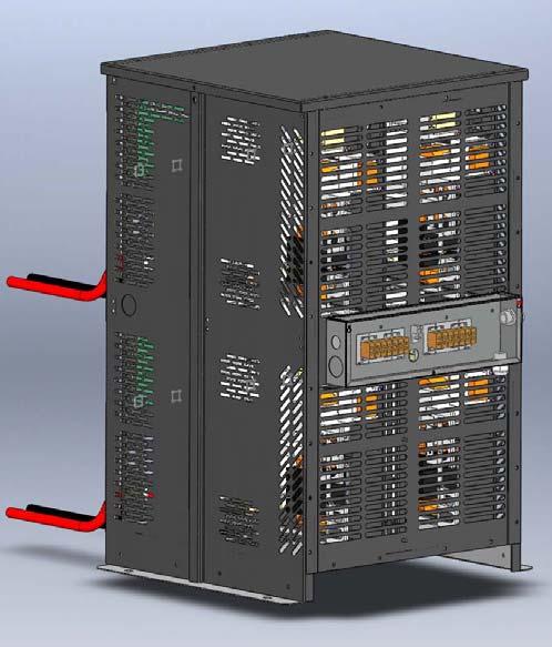
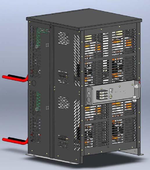
21 COMPLETE CABINET APPEARANCE QUAD AC INPUT SINGLE AC INPUT 20
22 COMPLETE CABINET APPEARANCE 21
23 MAINTENANCE LOG 1. Modifications to Factory Settings Date Variable Change Service Technician 2. Service Date Description Service Technician 22
Palomino BATTERY CHARGERS. Installation and Operating Instructions. One Technology Place Caledonia, New York The Power of Excellence
 Palomino BATTERY CHARGERS Installation and Operating Instructions One Technology Place Caledonia, New York 14423 The Power of Excellence FM1320 REV - B IMPORTANT SAFETY INSTRUCTIONS INSTRUCTIONS IMPORTANTES
Safety, Installation and Operating Instructions Instructions importantes concernant la sécurité
 ! Safety, Installation and Operating Instructions Instructions importantes concernant la sécurité Manual for the following Battery Fuel Gauge models: BFGOV12V, BFGOV24V, BFGOV36V, BFGOV48V, BFGOV64V and
SINGLE SHIFT & MULTI SHIFT
 Service Manual Ferroresonant Transformer Type Battery Charger SINGLE SHIFT & MULTI SHIFT SERIES I.B. 1501 Rev. D IND: 813 This page was intentionally left blank. AC LINE VOLTAGE LETTER CODES The following
STEED WITH CONTROLLED FERRO-RESONANT TECHNOLOGY
 STEED WITH CONTROLLED FERRO-RESONANT TECHNOLOGY Installation and Operating Instructions One Technology Place Caledonia, NY 14423 (585) 538 4421 www.appliedenergysol.com The Power of Excellence FM1249 REV
Troubleshooting Guide
 Troubleshooting Guide Current Revision: June 2009 Table of Contents PAGE IMPORTANT NOTES ------------------------------------------------------------------- 3 20T Main Electrical System --------------------------------------------------------------
Safety, Installation and Operating Instructions Instructions importantes concernant la sécurité
 Safety, Installation and Operating Instructions Instructions importantes concernant la sécurité Manual for the Following Battery Discharger: BD6812QUAD 022118-70329 IMPORTANT NOTICE: Please save and read
WorkHorse Series 3 Ferroresonant Battery Chargers
 WorkHorse Series 3 Ferroresonant Battery Chargers FEATURING dv/dt-di/dt CONTROLS Installation and Operating Instructions www.appliedenergysol.com One Technology Place Caledonia, NY 14423 (585) 538 4421
Section ENERSYS, INC. TECHNICAL SERVICE MANUAL FOR DEPTH CHARGER THREE PHASE MODEL D3E I.B REV F
 Section 28.41 ENERSYS, INC. TECHNICAL SERVICE MANUAL FOR DEPTH CHARGER THREE PHASE MODEL D3E I.B. 1411 REV F TABLE OF CONTENTS Introduction... 3 Theory of Operation... 3 Charger Parameters... 5 Transformer
Safety, Installation and Operating Instructions Instructions importantes concernant la sécurité
 Safety, Installation and Operating Instructions Instructions importantes concernant la sécurité Manual for the Following Battery Charger Models: 1250OB, 2440OB, 2450OB and 4836OB 030713 IMPORTANT NOTICE:
LESTRONIC II BATTERY CHARGER MODEL 07210
 LESTRONIC II BATTERY CHARGER MODEL 07210 PLEASE SAVE THESE IMPORTANT SAFETY AND OPERATING INSTRUCTIONS For correct operation of the equipment, it is important to read and be familiar with this entire manual
STEED GEL WITH CONTROLLED FERRO-RESONANT TECHNOLOGY
 STEED GEL WITH CONTROLLED FERRO-RESONANT TECHNOLOGY Installation and Operating Instructions One Technology Place Caledonia, NY 14423 (585) 538-4421 www.appliedenergysol.com The Power of Excellence FM1279
LegaC 2 Battery Charger Owner s Manual
 Model: DL1/DL3 LegaC 2 Battery Charger Owner s Manual To automatically be connected to your closest Service Center, call us toll-free at 1-800-DOUGLAS (1-800-368-4527) Or, visit us at: http://www.douglasbattery.com/
Safety, Installation and Operating Instructions Instructions importantes concernant la sécurité
 Safety, Installation and Operating Instructions Instructions importantes concernant la sécurité Manual for the Following Battery Charger Models i2412, i3612, i4809, i2425, i3625, and i4818 081808 IMPORTANT
SLM SWITCH MODE INDUSTRIAL BATTERY CHARGER USER S MANUAL. Important Safety, Installation, Operation, and Maintenance Instructions
 SLM 24-25 SWITCH MODE INDUSTRIAL BATTERY CHARGER USER S MANUAL Important Safety, Installation, Operation, and Maintenance Instructions www.lesterelectrical.com NOTES SLM 24-25 2 of 18 User s Manual CHARGER
Safety, Installation and Operating Instructions Instructions importantes concernant la sécurité
 Safety, Installation and Operating Instructions Instructions importantes concernant la sécurité Manual for the Following Battery Charger Models: 1212, 1212OB, 1225, 1225OB, 2412, 2412OB, 2420, 2420OB,
MODEL 6010A 6 12 VOLT BATTERY CHARGER ASSOCIATE
 MODEL 600A 6 VOLT BATTERY CHARGER ASSOCIATE IMPORTANT SAFETY INSTRUCTIONS. SAVE THESE INSTRUCTIONS. This manual contains important safety and operating instructions for the battery charger you have purchased.
Safety, Installation and Operating Instructions Instructions importantes concernant la sécurité
 Safety, Installation and Operating Instructions Instructions importantes concernant la sécurité Manual for the Following Battery Charger Models: 1212, 1212OB, 2412, 2412OB, 3612, 3612OB, 3617, 3617OB,
OPERATOR'S MANUAL IMPORTANT SAFETY INSTRUCTIONS
 ASSOCIATED OPERATOR'S MANUAL IMPORTANT SAFETY INSTRUCTIONS MODEL 6366 12 VOLT, 0-20 AMP 4 X 20 BATTERY CHARGER 1. SAVE THESE INSTRUCTIONS. This manual contains important safety and operating instructions
MODEL ELC-12/60-D BATTERY CHARGER
 *32198* NATIONAL RAILWAY SUPPLY Installing, Operating and Service Instructions for the 12/60 Solid State Charger MODEL ELC-12/60-D BATTERY CHARGER PLEASE SAVE THESE IMPORTANT SAFETY AND OPERATING INSTRUCTIONS
LS/ CCS. Constant Current Charger
 LS/ CCS Constant Current Charger Installation and Operation Manual CC_13 1 INDEX Page Section Description 3 - Safety Instructions 4 1.0 Installation 4 1.1 Receiving 4 1.2 Location 4 1.3 Line Voltage Adjustments
USER S MANUAL Industrial Battery Charger Important Safety, Installation, Operation, and Maintenance Instructions
 USER S MANUAL Industrial Battery Charger Important Safety, Installation, Operation, and Maintenance Instructions www.lesterelectrical.com CHARGER RATINGS LABEL The ratings label is located on the back
BATTERY CHARGER AR-D
 BATTERY CHARGER AR-D USER'S MANUAL (THIS PAGE WAS INTENTIONALLY LEFT BLANK) TABLE OF CONTENTS...3...3...3...3...3...3...3 1. Introduction...4 RESPONSIBILITY DISCLAIMER...4 2. Safety instructions and warnings...5
MODEL ELC-12/40-CVM-D BATTERY CHARGER
 NATIONAL RAILWAY SUPPLY MODEL ELC-12/40-CVM-D BATTERY CHARGER Installing, Operating and Service Instructions for the ELC-12/40-CVM-D Solid State Charger PLEASE SAVE THESE IMPORTANT SAFETY AND OPERATING
DISCHARGER-ANALYZER BDX USER'S MANUAL
 BATTERY DISCHARGER-ANALYZER BDX USER'S MANUAL OWM-BDX-261006 Page 1/10 1. INTRODUCTION Before starting to use your BDX battery discharger/analyzer, please take the time to read these instructions carefully.
USER S MANUAL Industrial Battery Charger Important Safety, Installation, Operation, and Maintenance Instructions
 USER S MANUAL Industrial Battery Charger Important Safety, Installation, Operation, and Maintenance Instructions www.lesterelectrical.com CHARGER RATINGS LABEL The ratings label is located on the back
LESTRONIC II BATTERY CHARGER BUILT-IN OR PORTABLE CHARGERS
 LESTRONIC II BATTERY CHARGER BUILT-IN OR PORTABLE CHARGERS PLEASE SAVE THESE IMPORTANT SAFETY AND OPERATING INSTRUCTIONS For correct operation of the equipment, it is important to read and be familiar
GV-10 Manual 10.5A / 140W IMPORTANT SAFETY INSTRUCTIONS SAVE THESE INSTRUCTIONS. Solar Charge Controllers with Maximum Power Point Tracking
 GV-10 Manual Solar Charge Controllers with Maximum Power Point Tracking For models: GV-10-Pb-12V: GV-10-Pb-CV: 12V Lead-Acid/AGM/Gel/Sealed/Flooded 12V Custom Multi-Stage Lead-Acid/AGM/Gel/ Sealed/Flooded
LESTRONIC II BATTERY CHARGER MODEL 19740
 *01679* LESTRONIC II BATTERY CHARGER MODEL 19740 PLEASE SAVE THESE IMPORTANT SAFETY AND OPERATING INSTRUCTIONS For correct operation of the equipment, it is important to read and be familiar with this
ST Charger. Industrial Battery Charger
 ST Charger Industrial Battery Charger Installation and Operation Manual ST_13 Table of Contents Pg# 1.0 INSTALLATION 1 1.1 Receiving 1 1.2 Location 1 1.3 Line Voltage 1 1.4 A.C. Service Requirements 2
AC CONVERTER / BATTERY CHARGER
 AC CONVERTER / BATTERY CHARGER User s Manual MODEL #: CON120AC12/24VDC Listed to UL 458 and CSA 22.2 NO. 107.1 Standards Contents INTRODUCTION... 3 Important Safety Instructions... 3 1. General Description...
PUMP PLUS 2000 PLC MODEL #: PP AUTOMATIC DUAL OUTPUT BATTERY CHARGER INSTRUCTION MANUAL
 INSTRUCTION MANUAL PUMP PLUS 2000 PLC AUTOMATIC DUAL OUTPUT BATTERY CHARGER Supplied with Dual Bar Graph Display MODEL #: 091-237-12-PP INPUT: 120 Volt, 60 Hz, 3.5 Amps OUTPUT BATTERY 1 and 2: 15 or 18
MINE CHARGER INSTALLATION AND OPERATION MANUAL MODEL NUMBERS: MSP MSQ MSR MSS
 MINE CHARGER INSTALLATION AND OPERATION MANUAL MODEL NUMBERS: MSP MSQ MSR MSS Sec# Table of Contents Pg# 1 INSTALLATION 1.1 Receiving 1 1.2 Location 1 1.3 Line Voltage Adjustments 2 1.4 A.C. Service Requirements
OWNERS MANUAL BATTERY CHARGER MODEL 19300
 *34943* OWNERS MANUAL BATTERY CHARGER MODEL 19300 Specifications AC Input: 108-125 Volts AC, 60 Hertz, single-phase, 10.5 amps DC Output: 36 Volts DC, 21 amps tapering to 6 @ 45 VDC Connections: 9 1/4
Art. No. EC-315. Art. No. EC-330. Art. No. EC-340 SWITCH-MODE BATTTERY CHARGER CONTENTS IMPORTANT SAFETY PRECAUTIONS... 2
 SWITCH-MODE BATTTERY CHARGER CONTENTS IMPORTANT SAFETY PRECAUTIONS... 2 DESCRIPTION AND FEATURES... 3 CHARGING STAGES... 4 Art. No. EC-315 Art. No. EC-330 Art. No. EC-340 PROTECTIONS... 5 INSTALLATION...
OBE, OBEXU, ON BOARD Battery Chargers
 C O R P O R A T IO N O P E R A T I N G I N S T R U C T I O N S OBE, OBEXU, ON BOARD Battery Chargers INTRODUCTION: These chargers are designed for the permanent installation on battery powered vehicles
SOLAR CHARGE CONTROLLER
 SOLAR CHARGE CONTROLLER SCE 1010 / SCE 1515 / SCE 2020 / SCE 3030 Instruction Manual Please read user manual carefully before use. 1.About this manual These operating instructions are part of the product.
LOADHOG BATTERY CHARGER
 Section 8.68 Installation and Operating Instructions for LOADHOG Solid State Charger LOADHOG BATTERY CHARGER PLEASE SAVE THESE IMPORTANT SAFETY AND OPERATING INSTRUCTIONS For correct operation of the equipment,
MULTIVOLTAGE PORTABLE BATTERY CHARGER MVM
 _ M MULTIVOLTAGE PORTABLE BATTERY CHARGER MVM User's MANUAL Code: MVM Version: 01-BF Date: OCT 2005 Page 1/10 _ 1. INTRODUCTION Before starting to use your Energic plus MVM battery charger, please take
SWITCH MODE INDUSTRIAL BATTERY CHARGER USER S MANUAL
 SWITCH MODE INDUSTRIAL BATTERY CHARGER USER S MANUAL Important Safety, Installation, Operation, and Maintenance Instructions www.lesterelectrical.com CHARGER RATINGS LABEL The ratings label is located
User s Manual. Automatic Switch-Mode Battery Charger
 User s Manual Automatic Switch-Mode Battery Charger IMPORTANT Read, understand, and follow these safety rules and operating instructions before using this battery charger. Only authorized and trained service
AUTO CHARGE 11 MODEL #: XX. AUTOMATIC BATTERY CHARGER U.L. Configuration INSTRUCTION MANUAL
 INSTRUCTION MANUAL AUTO CHARGE 11 AUTOMATIC BATTERY CHARGER U.L. Configuration MODEL #: 091-11-XX NOTE : This charger is designed for vehicles with dual batteries and negative ground. CAUTION This unit
GVB-8 (Boost) Manual
 Manual") GVB-8 (Boost) Manual Solar Charge Controllers with Maximum Power Point Tracking For models: GVB-8-Pb-12V: 12V Lead-Acid/AGM/Gel/Sealed/Flooded GVB-8-Pb-24V: GVB-8-Pb-36V: GVB-8-Pb-48V: GVB-8-Pb-CV: 24V
GVB-8 (Boost) Manual Solar Charge Controllers with Maximum Power Point Tracking For models: GVB-8-Pb-12V: 12V Lead-Acid/AGM/Gel/Sealed/Flooded GVB-8-Pb-24V: GVB-8-Pb-36V: GVB-8-Pb-48V: GVB-8-Pb-CV: 24V
DBL Manual. Deutronic Battery Charger with MPC4-Board and 14VDC output voltage (12VDC lead based batteries)
") Deutronicstrasse 5 D-84166 Adlkofen / Germany Tel.: +49 (0)8707 / 920-199 Fax: +49 (0)8707 / 1004 E-Mail: sales@deutronic.com http://www.deutronic.com DBL Manual Deutronic Battery Charger with MPC4-Board
Deutronicstrasse 5 D-84166 Adlkofen / Germany Tel.: +49 (0)8707 / 920-199 Fax: +49 (0)8707 / 1004 E-Mail: sales@deutronic.com http://www.deutronic.com DBL Manual Deutronic Battery Charger with MPC4-Board
MODEL A96 SERIES. 130Vdc Switchmode Utility Rectifier / Battery Charger. Used with LaMarche Power Cage ECN/DATE
 MODEL A96 SERIES 130Vdc Switchmode Utility Rectifier / Battery Charger Used with LaMarche Power Cage CPN112138 ECN/DATE ISSUE DATE: ECN 17010-12/05 106 BRADROCK DRIVE DES PLAINES, IL. 60018-1967 (847)
12V 1 AMP (1000 ma) Automatic Battery Charger & Maintainer
 Automatic Battery Charger & Maintainer") 12V 1 AMP (1000 ma) Automatic Battery Charger & Maintainer For lead-acid batteries THIS MANUAL CONTAINS IMPORTANT SAFETY AND OPERATING INSTRUCTIONS FOR 12V BATTERY CHARGER: YUA1201000 / INT1201000 KEEP
12V 1 AMP (1000 ma) Automatic Battery Charger & Maintainer For lead-acid batteries THIS MANUAL CONTAINS IMPORTANT SAFETY AND OPERATING INSTRUCTIONS FOR 12V BATTERY CHARGER: YUA1201000 / INT1201000 KEEP
INSTALLATION INSTRUCTIONS LED Canopy Retrofit Kit
 INSTALLATION INSTRUCTIONS LED Canopy Retrofit Kit TRMUNV065ECxyyZ TRAUNV065ECxyyZ Installation Instructions subject to change without notice. Page 1 of 8 1.0 INSTALLATION WARNINGS 1. 2. 3. 4. 5. 6. "THIS
IMPORTANT SAFETY INSTRUCTIONS IMPORTANT: READ AND SAVE THIS SAFETY AND INSTRUCTION MANUAL. KEEP IT WITH OR NEAR CHARGER AT ALL TIMES.
 IMPORTANT SAFETY INSTRUCTIONS IMPORTANT: READ AND SAVE THIS SAFETY AND INSTRUCTION MANUAL. KEEP IT WITH OR NEAR CHARGER AT ALL TIMES. SPECIFICATIONS: For technical assistance, call your Dealer with the
PUMP PLUS 1000 PLC MODEL #: PP AUTOMATIC SINGLE OUTPUT BATTERY CHARGER INSTRUCTION MANUAL
 INSTRUCTION MANUAL PUMP PLUS 1000 PLC AUTOMATIC SINGLE OUTPUT BATTERY CHARGER Unit supplied with one of these displays MODEL #: 091-215-12-PP INPUT: 120 Volt, 60 Hz, 3.5 Amps OUTPUT BATTERY 1 and 2: 15
Safety, Installation And Operating Instructions For The Following Battery Charger Models: i2412, i3612, i4809, i2425, i3625, and i4818
 Safety, Installation And Operating Instructions For The Following Battery Charger Models: i2412, i3612, i4809, i2425, i3625, and i4818 IMPORTANT NOTICE: Please save and read these safety, operating and
12 VOLT 30 AMP DIGITAL SOLAR CHARGE CONTROLLER
 12 VOLT 30 AMP DIGITAL SOLAR CHARGE CONTROLLER User s Manual Congratulations on your Coleman solar product purchase. This product is designed to the highest technical specifications and standards. It will
A39 UNIVERSAL SCR CHARGER
 A39 UNIVERSAL SCR CHARGER ECN/DATE CPN35971 21681 01/18 16816-6/05 15349-03 05/02 14575 02/01 14268 10/00 10400 9/96 106 BRADROCK DRIVE DES PLAINES, IL. 60018-1967 (847) 299-1188 FAX: (847) 299-3061 ISSUE
4.2 Component Identification
 Digital Control Panels Deep Sea Electronics 5220 4.1 General 4.2 Component Identification 4.3 The YML5220 Controller 4.4 Description of Controls 4.5 Navigation 4.5.1 General Navigation 4.5.2 The Event
ACC Series Power Conditioner OPERATION & INSTALLATION MANUAL
 ACC Series Power Conditioner OPERATION & INSTALLATION MANUAL PHASETEC digital power conditioners are designed to safely operate electrical equipment in the harshest power quality environments. With a wide
SWITCH MODE INDUSTRIAL BATTERY CHARGER USER S MANUAL
 SWITCH MODE INDUSTRIAL BATTERY CHARGER USER S MANUAL Important Safety, Installation, Operation, and Maintenance Instructions www.lesterelectrical.com CHARGER RATINGS LABEL The ratings label is located
Installation Instructions
 PART NUMBER: CPLPCONV007A00 60,000---130,000 BTU/HR 2TO5TONS SMALL PACKAGED PRODUCTS GAS HEATING/ELECTRIC COOLING UNITS HIGH ALTITUDE ONLY 2001---6000 FT PROPANE CONVERSION KIT Installation Instructions
AUTO CHARGE 4000 MODEL #: LOW PROFILE CHARGER AUTOMATIC DUAL OUTPUT BATTERY CHARGER INSTRUCTION MANUAL
 INSTRUCTION MANUAL AUTO CHARGE 4000 LOW PROFILE CHARGER AUTOMATIC DUAL OUTPUT BATTERY CHARGER Unit supplied with this display MODEL #: 091-89-12 INPUT: 120 Volt, 50/60 Hz, 5 Amps OUTPUT: 45 Amps File:
SP6. Automatic Battery Charger. Model
 Model SP6 Automatic Battery Charger OWNERS MANUAL PLEASE SAVE THIS OWNERS MANUAL AND READ BEFORE EACH USE. This manual will explain how to use the charger safely and effectively. Please read and follow
LESTRONIC II FULLY AUTOMATIC BATTERY CHARGER MODEL TYPE 36LC36-8ET
 *01492* LESTRONIC II FULLY AUTOMATIC BATTERY CHARGER MODEL 17090 TYPE 36LC36-8ET AC Input: DC Output: Connections: Specifications 108-128 Volts AC, 15 Amp, 60 Hertz, single-phase 36 Volts DC, 36 Amp 6-
LPC 40 MODEL #: LOW PROFILE CHARGER WITH PLC AUTOMATIC SINGLE OUTPUT BATTERY CHARGER INSTRUCTION MANUAL
 INSTRUCTION MANUAL LPC 40 LOW PROFILE CHARGER WITH PLC AUTOMATIC SINGLE OUTPUT BATTERY CHARGER Unit supplied with one of these displays MODEL #: 091-200-12 INPUT: 120 Volt, 50/60 Hz, 5 Amps OUTPUT: 40
GVB-8 (Boost) Manual
 Manual") www.genasun.com GVB-8 (Boost) Manual Solar Charge Controllers with Maximum Power Point Tracking For models: GVB-8-Pb-12V: 12V Lead-Acid/AGM/Gel/Sealed/Flooded GVB-8-Pb-24V: 24V Lead-Acid/AGM/Gel/Sealed/Flooded
www.genasun.com GVB-8 (Boost) Manual Solar Charge Controllers with Maximum Power Point Tracking For models: GVB-8-Pb-12V: 12V Lead-Acid/AGM/Gel/Sealed/Flooded GVB-8-Pb-24V: 24V Lead-Acid/AGM/Gel/Sealed/Flooded
OBAE, OBAEXU, ON BOARD Battery Chargers
 C O R P O R A T IO N O P E R A T I N G I N S T R U C T I O N S OBAE, OBAEXU, ON BOARD Battery Chargers INTRODUCTION: The OBAE line of chargers are designed for the permanent installation on battery powered
CSD Series Current Devices Split Core
 CSD Series Current Devices Split Core Installation Instructions CSD-CF0A0-1 CSD-CF0J0-1 CSD-CA1G0-1 Part. 24-10345-34, Rev. D Issued March 31, 2014 Supersedes April 5, 2013 Applications The Current Switch
SR2400, SR4803, SR6000
 _ EAGLETRONIC MTL2 SR2400, SR4803, SR6000 USER'S MANUAL V2.0 May 2006 www.batterychargers.it Page 1/18 _ INDEX 1. SAFETY INSTRUCTIONS AND WARNINGS... 3 GENERAL... 3 SHOCK PREVENTION... 3 BURN AND BODILY
MODEL 6017 OPERATOR'S MANUAL
 MODEL 6017 OPERATOR'S MANUAL ASSOCIATE D IMPORTANT SAFETY INSTRUCTIONS 1. SAVE THESE INSTRUCTIONS. This manual contains important safety and operating instructions for the battery charger you have purchased.
DSP Standby Battery Charger
 DSP Standby Battery Charger 205B Konrad Cres., Markham, ON, L3R 8T9 www.chargers.ca Building Canada s toughest battery chargers for over a century. Congratulations on your purchase of a quality built,
IMPORTANT SAFETY INSTRUCTIONS
 1163714 1.5 AMP 12VOLT TRICKLE 1.5 AUTOMATIC AMP AUTOMATIC TRICKLE 1.5 AMP AUTOMATIC 12V12VOLT BATTERY CHARGER IMPORTANT SAFETY INSTRUCTIONS 1. SAVE THESE INSTRUCTIONS This product offers a wide range
Captivate Illuminated Mirror Light
 ENGLISH WARNINGS & SAFETY INFORMATION: PLEASE READ CAREFULLY FRANÇAIS MISES EN GARDE ET SÉCURITÉ: SE IL VOUS PLAÎT LIRE ATTENTIVEMENT WARNING: RISK OF FIRE OR ELECTRIC SHOCK. LUMINAIRE WIRING AND ELECTRICAL
STEP-BY-STEP INSTALLATION GUIDE
 Battery Backup System STEP-BY-STEP INSTALLATION GUIDE Operating Instructions & Parts Manual ESP25 Please read and save these instructions. Read carefully before attempting to assemble, install, operate
AUTO CHARGE D2 MODEL #: AUTOMATIC TRIPLE OUTPUT BATTERY CHARGER INSTRUCTION MANUAL
 INSTRUCTION MANUAL AUTO CHARGE D2 AUTOMATIC TRIPLE OUTPUT BATTERY CHARGER Designed Specifically for Vehicles with DDEC ENGINES MODEL #: 091-74-12 INPUT: 120 Volt, 60 Hz, 8 Amps OUTPUT VEHICLE BATTERY 1
Installation and operating instructions. Solar charge controller MPPT 10 A / 20 A Z Z
 Installation and operating instructions Solar charge controller MPPT 10 A / 20 A EN 1 Contents 1. About these instructions... 3 1.1 Applicability... 3 1.2 Users... 3 1.3 Description of symbols... 3 2.
MODEL A97 SERIES. Switchmode Utility Rectifier/Battery Charger ECN/DATE
 MODEL A97 SERIES Switchmode Utility Rectifier/Battery Charger CPN108172 ISSUE DATE: 16071 7/03 ECN/DATE 106 BRADROCK DRIVE DES PLAINES, IL. 60018-1967 (847) 299-1188 FAX: (847)299-3061 Page 1 of 7 INSTRUCTION
24 VOLT AUTOMATIC BATTERY CHARGER PART NO
 24 VOLT AUTOMATIC BATTERY CHARGER PART NO. 957732 AC Input: DC Output: Battery Type: Specifications 230 volts, 50 hertz, 3.5 amps, single-phase 24 volts, 20 amps initially tapering to 6 amps 24 volt, 12
Specification Grade Contemporary Wall Mount/Technical Installation Data
 AVAILABLE CONFIGURATIONS RECESSED MOUNT SURFACE MOUNT MOUNTING REQUIREMENTS A. Recessed Mount: Minimum 4-Gang Box, 1-5/8 in. Deep (72.8 Cubic Inches) with 4-Gang Box Cover (20.3 Cubic Inches) B. Surface
CX-SERIES ADVANCED BATTERY CHARGER
 CX-SERIES ADVANCED BATTERY CHARGER Table of Content 1. IMPORTANT SAFETY INFORMATION... 2 1-1 General Safety Precautions... 2 1-2 Battery Precautions... 2 2. FEATURES... 3 2-1 Battery Charging Curve...
Service Manual BLACK DIAMOND SERVICE MANUAL. V.160 November
 BLACK DIAMOND SERVICE MANUAL V.160 November 2011 www.montrealchargeur.com www.battelec.ca www.doctorfleet.com Page 1/30 1. SAFETY PRECAUTIONS 1 Before to start using the Black Diamond Charger, read these
Deep Cycle Battery Safety. First. Battery Handling, Maintenance & Test Procedures
 Deep Cycle Battery Safety. First. Battery Handling, Maintenance & Test Procedures Crown deep cycle batteries employ a low-maintenance design. They do require periodic maintenance and effective charging
AUTO CHARGE 4000 MODEL #: AUTOMATIC DUAL OUTPUT BATTERY CHARGER INSTRUCTION MANUAL. Ph: Fax:
 INSTRUCTION MANUAL AUTO CHARGE 4000 AUTOMATIC DUAL OUTPUT BATTERY CHARGER MODEL #: 091-89-12 INPUT: 120 Volt, 50/60 Hz, 8 Amps OUTPUT BATTERY CHARGER: 40 Amps OUTPUT BATTERY SAVER: 5 Amps File: IM_091-89-12_reve.indd
801 BUSINESS CENTER DRIVE MOUNT PROSPECT, ILLINOIS
 280-600 Send Warranty Product Repairs to: 1025 E. Thompson Ave., Hoopeston, IL 60942-0280. Call Customer Service if you have questions: 1-800-621-5485 A. IMPORTANT SAFETY INSTRUCTIONS 1. SAVE THESE INSTRUCTIONS
AUTO CHARGE D PUMP PLUS
 INSTRUCTION MANUAL AUTO CHARGE D PUMP PLUS AUTOMATIC DUAL OUTPUT BATTERY CHARGER Designed Specifically for Vehicles with DDEC ENGINES MODEL #: 091-9-DPP INPUT: 120 Volt, 60 Hz, 8 Amps OUTPUT VEHICLE BATTERY:
Models: SP3, SPSS3 Automatic Battery Charger
 OWNERS MANUAL Models: SP3, SPSS3 Automatic Battery Charger PLEASE SAVE THIS OWNERS MANUAL AND READ BEFORE EACH USE. This manual will explain how to use the charger safely and effectively. Please read and
LESTRONIC II BATTERY CHARGER TAYLOR-DUNN MODEL TYPE 24LC25-8ET
 LESTRONIC II BATTERY CHARGER TAYLOR-DUNN 79-301-10 MODEL 13110-32 TYPE 24LC25-8ET AC Supply: DC Output: Battery Capacity: Specifications 120 volts, 60 Hertz, single-phase 24 volts, 32 amps Use only on
FC/FCA 12, 24, 32 & 48 VOLT, 6 & 10 AMP BATTERY CHARGER OPERATION & MAINTENANCE GUIDE
 FC/FCA 12, 24, 32 & 48 VOLT, 6 & 10 AMP BATTERY CHARGER OPERATION & MAINTENANCE GUIDE SENS part number: 101037 Document revision: A Engineering change number: 105073 Date: 1/13/2006 1840 Industrial Circle
Technical manual. Hawker SmarTech. three phase
 Technical manual GB Hawker SmarTech three phase ENGLISH Contents Warning Contents... Warning... Aim of this manual... Guarantee... Recommendations... Electrical safety... Limitations on use... Recycling
LPC 20 MODEL #: LOW PROFILE CHARGER AUTOMATIC SINGLE OUTPUT BATTERY CHARGER INSTRUCTION MANUAL
 INSTRUCTION MANUAL LPC 20 LOW PROFILE CHARGER AUTOMATIC SINGLE OUTPUT BATTERY CHARGER Unit supplied with one of these displays MODEL #: 091-207-12 INPUT: 120 Volt, 50/60 Hz, 7 Amps OUTPUT: 20 Amps File:
IMPORTANT SAFEGUARDS When using electrical equipment, basic safety precautions should always be followed including the following:
 ZR-RK Series LED Retrofit Troffer Kit Includes: ZR22RK and ZR24RK Standard and Emergency Luminaires IMPORTANT SAFEGUARDS When using electrical equipment, basic safety precautions should always be followed
INSTALLATION INSTRUCTIONS MOONRING 1 LP1/MR1
 INSTALLATION INSTRUCTIONS MOONRING 1 LP1/MR1 Suspended, Ceiling LED n A 1035 22nd Avenue, Unit 1 Oakland, CA 94606 P 510.489.2530 E TalkToUs@alwusa.com W alwusa.com Safety & Warnings! 1. Read all instructions.
BOOST POWER 1212 Product Description
 BOOST POWER 1212 Product Description Contents 1 Introduction...4 2 General Description...4 2.1 Compatibility with standard Lead-Acid Batteries... 4 3 Battery Performance...5 3.1 Discharge Capability...
MOONRING 1.5 MOONRING 3
 INSTALLATION INSTRUCTIONS MOONRING 1.5 MOONRING 3 MR1.5 & MR3 Suspended, Ceiling LED n A 1035 22nd Avenue, Unit 1 Oakland, CA 94606 P 510.489.2530 E TalkToUs@alwusa.com W alwusa.com Safety & Warnings!
SOLAR CHARGE CONTROLLER N 2010 IN 2011/ N 2012/ N 2014
 SOLAR CHARGE CONTROLLER N 2010 IN 2011/ N 2012/ N 2014 Instruction Manual Please read user manual carefully before use. CE 1.About this manual These operating instructions are part of the product. ~ Read
MP V 8A Electronic Smart Charger. Instruction and Information Manual
 MP7428 12V 8A Electronic Smart Charger Instruction and Information Manual In order to ensure correct and safe usage of your battery charger, you should read these instructions carefully. Please retain
INSTALLATION INSTRUCTIONS FOR Owner's Copy FILTERED AND REGULATED POWER SUPPLY VOLTS DC INPUT: Hz.
 103158 March 9, 2011 FOR INDOOR USE ONLY Detex Corporation, 302 Detex Drive, New Braunfels, Texas 78130-3045 (830)629-2900 / 1-800-729-3839 / Fax (830)620-6711 E-MAIL: detex@detex.com INTERNET: www.detex.com
Maintenance Manual 13 AMPERE POWER SUPPLY 19A704647P1-P3. Mobile Communications LBI-31801C
 C Mobile Communications 13 AMPERE POWER SUPPLY 19A704647P1-P3 CAUTION THESE SERVICING INSTRUCTIONS ARE FOR USE BY QUALI- FIED PERSONNEL ONLY. TO AVOID ELECTRIC SHOCK DO NOT PERFORM ANY SERVICING OTHER
SOS SERIES SOS1 SOS2. Spares On Site Battery Cabinet Installation Guide rEV3
 Atlantic Battery Systems 1065 Market Street Paterson, NJ 07513 Phone: (800) 875-0073 Fax: (973) 523-2344 sales@atbatsys.com www.atbatsys.com SOS1 SOS2 SOS SERIES Spares On Site Battery Cabinet Installation
PHOTOVOLTAIC SYSTEM CONTROLLERS SUNSAVER MODELS INCLUDED IN THIS MANUAL SS-6 / SS-6L SS-10 / SS-10L SS-10-24V / SS-10L-24V SS-20L SS-20L-24V
 PHOTOVOLTAIC SYSTEM CONTROLLERS OPERATOR S MANUAL SUNSAVER MODELS INCLUDED IN THIS MANUAL SS-6 / SS-6L SS-10 / SS-10L SS-10-24V / SS-10L-24V SS-20L SS-20L-24V 6A / 12V 10A / 12V 10A / 24V 20A / 12V 20A
Installation and Operating Instructions. MPPT Solar System Controller ISC3040
 Installation and Operating Instructions MPPT Solar System Controller ISC3040 ABOUT THIS MANUAL These operating instructions come with the product and should be kept with it as a reference to all user s
INSTALLATION, OPERATION & MAINTENANCE SERIES ABC11B-120-XX BATTERY CHARGERS
 MANUAL NUMBER: 64073 REV: 2 DATE: October 3, 2006 INSTALLATION, OPERATION & MAINTENANCE SERIES ABC11B-120-XX BATTERY CHARGERS AMERICAN BATTERY CHARGING, INC. P.O. BOX 17040 28 MAPLE AVENUE SMITHFIELD,
AUTO CHARGE DUAL MODEL #: AUTOMATIC DUAL OUTPUT BATTERY CHARGER INSTRUCTION MANUAL. Ph: Fax:
 INSTRUCTION MANUAL AUTO CHARGE DUAL AUTOMATIC DUAL OUTPUT BATTERY CHARGER MODEL #: 091-145-12 INPUT: 120 Volt, 50/60 Hz, 3.5 Amps OUTPUT BAT 1: 10 Amps OUTPUT BAT 2: 10 Amps File: IM_091-145-12_revb.indd
AUTO CHARGE 12 HO MODEL #: MODEL #: MODEL #: AUTOMATIC SINGLE OUTPUT BATTERY CHARGER INSTRUCTION MANUAL
 INSTRUCTION MANUAL AUTO CHARGE 12 HO AUTOMATIC SINGLE OUTPUT BATTERY CHARGER MODEL #: 091-170-6 MODEL #: 091-170-12 MODEL #: 091-170-24 File: IM_091-170-xx_revd.indd Rev: D Revised By: MFG Date: 10-23-2013
Installation and Operating Instructions. Solar System Controller ISC3030
 Installation and Operating Instructions Solar System Controller ISC3030 ABOUT THIS MANUAL These operating instructions come with the product and should be kept with it as a reference to all user s of the
Automatic Battery Charger Switching mode with Micro-controlled Input: Vac / Output: 12Volt DC
 Automatic Battery Charger Switching mode with Micro-controlled Input:100-140Vac / Output: 12Volt DC User s Manual and Important Safety Information Model: #20085 (SW121080-06) FEATURES Congratulations on