SR2400, SR4803, SR6000
|
|
|
- Sheena Barnett
- 6 years ago
- Views:
Transcription
1 _ EAGLETRONIC MTL2 SR2400, SR4803, SR6000 USER'S MANUAL V2.0 May Page 1/18
2 _ INDEX 1. SAFETY INSTRUCTIONS AND WARNINGS... 3 GENERAL... 3 SHOCK PREVENTION... 3 BURN AND BODILY INJURY PREVENTION... 4 FIRE AND EXPLOSION PREVENTION... 4 ARCING AND BURNING OF CONNECTOR... 4 MEDICAL AND FIRST AID TREATMENT DESCRIPTION OF THE CHARGER INSTALLATION OF THE CHARGER...6 AC INPUT CONNECTION... 7 AC INPUT VOLTAGE SELECTION 208/240/480VAC (ONLY FOR SR4803)... 7 AC INPUT VOLTAGE SETTINGS HOW TO USE THE CHARGER PROGRAMMATION OF THE GASSING POINT BATTERY CONNECTION VOLTAGE CHECK AND AUTOSTART CHARGE OPERATION SAFETY TIMER EMERGENCY STOP AUTOMATIC DATA SAVING BLOWN FUSE DETECTION AUTOMATIC CHARGE TERMINATION AUTOMATIC SHUTDOWN ON BATTERY DISCONNECTION EQUALIZE & REFRESH MODES MANUAL CHARGE TERMINATION SCHEMATICS & TABLES...18 Page 2/18
3 _ 1. SAFETY INSTRUCTIONS AND WARNINGS Before to start using your EAGLETRONIC MTL2 battery charger, please take the time to read these instructions carefully. The owner s manual is an important part of the charger. It s recommended to keep it in good condition for the lifetime of the charger. It should be kept in a dry and clean place, always available to the users. To indicate important instructions, the following blocks are used throughout this manual. GENERAL CAUTION! This operation can be dangerous for the user. ATTENTION! This operation is important for the functionality and reliability of the charger. Battery charging products can cause serious injury or death, or damage to other equipment or property, if the operator does not strictly observe all safety rules and take precautionary actions. Safe practices must be learned through study and training before using this equipment. Only qualified personnel should install, use, or service this equipment. SHOCK PREVENTION Bare conductors, or terminals in the output circuit, or ungrounded, electrically-live equipments can fatally shock a person. To protect against shock, have competent electrician verify that the equipment is adequately grounded and learn what terminals and parts are electrically HOT. The body s electrical resistance is decreased when wet, permitting dangerous current to flow through the body. Do not work in damp area without being extremely careful. Stand on dry rubber mat or dry wood and use insulating gloves when dampness or sweat cannot be avoided. Keep clothing dry. INSTALLATION AND GROUNDING - A power disconnect switch must be located at the equipment. Check the data label for voltage and phase requirements. If only 3-phase power is available, connect single-phase equipment to ONLY TWO WIRES of the 3-phase line. DO NOT CONNECT the equipment grounding conductor to the third live wire of the 3-phase line as this makes the equipment frame electrically HOT, which can cause a fatal shock. If a grounding conductor is part of the power supply cable, be sure to connect it to a properly grounded switch box or building ground. If not part of the supply cable, use a separate grounding conductor. Don t remove a ground prong from any plug. Use correct mating receptacles. Check ground for electrical continuity before using equipment. The grounding conductor must be of a size equal to or larger than the size of the line conductors. CHARGING LEADS Inspect leads often for damage to the insulation. Replace or repair cracked or worn leads immediately. Use leads having sufficient capacity to carry the operating current without overheating. BATTERY TERMINALS Do not touch battery terminals while equipment is operating. Page 3/18
4 _ SERVICE AND MAINTENANCE Shut OFF all power at the disconnect switch or line breaker BEFORE inspecting, adjusting, or servicing the equipment. Lock switch OPEN (or remove line fuses) so that the power cannot be turned ON accidentally. Disconnect power to equipment if it is to be left unattended or out of service. Disconnect battery from charger. Keep inside parts clean and dry. Dirt and/or moisture can cause insulation failure. This failure can result in high voltage at the charger output. BURN AND BODILY INJURY PREVENTION The battery produces very high currents when short circuited, and will burn the skin severely if in contact with any metal conductor that is carrying this current. Do not permit rings on fingers to come in contact with battery terminals or the cell connectors on top of the battery. Battery acid is very corrosive. Alwais wear correct eye and body protection when near batteries. FIRE AND EXPLOSION PREVENTION When batteries are being recharged, they generate hydrogen gas that is explosive in certain concentrations in air (the flammability or explosive limits are 4.1% to 72% hydrogen in air). The spark-retarding vents help slow the rate of release of hydrogen, but the escaping hydrogen may form an explosive atmosphere around the battery if ventilation is poor. The ventilation system should be designed to provide an adequate amount of fresh air for the number of batteries being charged. This is essential to prevent an explosion. Always keep sparks, flames, burning cigarettes, and other sources of ignition away from the battery recharging area. Do not break "live" circuits at the terminals of batteries. Do not lay tools or anything that is metallic on top of any battery. ARCING AND BURNING OF CONNECTOR To prevent arcing and burning of the connector contacts, be sure the charger is OFF before connecting or disconnecting the battery. The ammeter should NOT indicate current flow. MEDICAL AND FIRST AID TREATMENT First aid facilities and a qualified first aid person should be available for each shift for immediate treatment of electrical shock victims. EMERGENCY FIRST AID: Call phisician and ambulance immediately and use First Aid techniques recommended by the American Red Cross. DANGER: ELECTRICAL SHOCK CAN BE FATAL. If person is unconscious and electric shock is suspected, do not touch person if he or she is in contact with charging equipment, battery, charging leads, or other live electrical parts. Disconnect power at wall switch and then use First Aid. Dry wood, wooden broom, and other insulating material can be used to move cables, if necessary, away from person. IF BREATHING IS DIFFICULT, give oxygen. IF NOT BREATHING, BEGIN ARTIFICIAL BREATHING, such as mouth-to-mouth. IF PULSE IS ABSENT, BEGIN ARTIFICIAL CIRCULATION, such as external heart massage. In case of acid in the eyes, flush very well with clean water and obtain professional medical attention immediately. Page 4/18
5 _ 2. DESCRIPTION OF THE CHARGER EAGLETRONIC MTL2 battery chargers have been designed to charge Lead-Acid batteries. These units convert the AC input to a DC output at the correct voltage. The charge curve is of the type Wa. The operation of the EAGLETRONIC MTL2 chargers is managed by the new MTL2 Digital Charge Controller, which is a microprocessor based electronic board of the last generation. Important features of the MTL2 Digital charge controller are: Easy Programmation by DIP switches. Programmable Gassing Voltage. Proportional Algorithm for charge time calculation. Programmable Equalize System (Automatic Pulsed & Manual). Automatic voltage-controlled maintenance. Wrong battery detection. Battery desulphation cycle. Independent safety timer. Automatic data-saving in case of black out of the mains. Cyclical indication of V/cell, AMPS, Ah returned, time. Cool down time counter. Scrolling messages in plain text. The MTL2 Charge Controller monitors the entire charging curve, and it incorporates several safety features. The front panel of the MTL2 Digital charge controller contains the digital display (4-Digits), the STOP button and the MANUAL-EQUALIZE button. Page 5/18

6 _ 3. INSTALLATION OF THE CHARGER Conditions of use: Operating temperature: 5 C to 45 C Storage temperature: -20 C to 60 C Relative humidity: less than 75% CAUTION! Risk of electrical shock! The charger can be installed by qualified personnel only. To prevent fire or shock hazard, do not expose the unit to rain or moisture. Don't use the unit in presence of flammable gas, because it can generate sparks. ATTENTION! Make sure that the unit's maximum input power (reported on the data label) is available from your power supply, and verify that the unit's operating voltage is correct. Allow adequate air circulation to prevent internal heat buildup. Don't place the unit near heat sources such as radiators or air ducts, or in a place subject to direct sunlight, excessive dust, mechanical vibration or shock. Page 6/18

7 _ AC INPUT CONNECTION The charger must be connected to the AC input using an adequate cable and plug, with disconnect switch and fuses. The AC input wires have to be connected to the TERMINAL BLOCKS FOR AC INPUT WIRES, that are located on the right side of the internal panel, just under the AC input contactor. Make sure to tighten the terminal block screws with the proper torque, and pull each wire separately in order to verify that they are mounted properly. AC INPUT VOLTAGE SELECTION 208/240/480VAC (ONLY FOR SR4803) The model SR4803 can be configured for 208/240 VAC or 480 VAC nominal input voltage. This selection can be made with the / 480 VAC SELECTION BOARD, that is located at the center of the internal panel, near the terminal blocks for the AC input wires. Disconnect the charger from main supply and battery. Remove the plastic protection over the / 480 VAC SELECTION BOARD. Remove the three metal bars. Place the metal bars in the required position, with ref to the following pictures. Tighten the nuts with the proper torque. Apply the plastic protection. Connect the charger to main supply. SELECTION BOARD IN POSITION VAC SELECTION BOARD IN POSITION 480 VAC Page 7/18
8 _ AC INPUT VOLTAGE SETTINGS ATTENTION! The proper setting of the power transformer taps is fundamental for the correct operation of the EAGLETRONIC MTL2 chargers. If the real AC input voltage is different than the AC nominal voltage to which the charger is set, the charging current of the charger may be significantly different than the nominal. The POWER TRANSFORMER TAPS and the label with the list of the 5 NOMINAL voltages that are available, are located on the left side of the internal panel. SR2400 SR4800 SR x 250 VAC 3x 250 VAC --- 3x 500 VAC 3x 620 VAC 2 1x 240 VAC 3x 240 VAC --- 3x 490 VAC 3x 610 VAC 3 1x 224 VAC 3x 224 VAC --- 3x 480 VAC 3x 600 VAC 4 1x 208 VAC 3x 208 VAC --- 3x 460 VAC 3x 575 VAC 5 1x 200 VAC 3x 200 VAC --- 3x 440 VAC 3x 550 VAC Using an adequate AC-voltmeter, measure the value of the REAL AC input voltage available at the mounting location of the charger. Identify which of the 5 NOMINAL voltage values is closest to the REAL measured value. Example 1: Example 2: for a charger SR2400 (singlephase) if the measured voltage is 212 VAC, the transformer should be connected to the tap number 4, that corresponds to 208 VAC. for a charger SR6000 (threephase) if the measured voltage is 608 VAC, the transformer should be connected to the tap number 2, that corresponds to 610 VAC For the singlephase units (SR2400), the wires to be moved are the TWO that are connected to the AC contactor, marked with the letter A. For the threephase units (SR4803 SR6000), the wires to be moved are the THREE that are connected to the AC contactors, marked with the letters A, B and C. Page 8/18
")
")
9 _ Singlephase units (SR2400) Threephase units (SR4803 & SR6000) Page 9/18

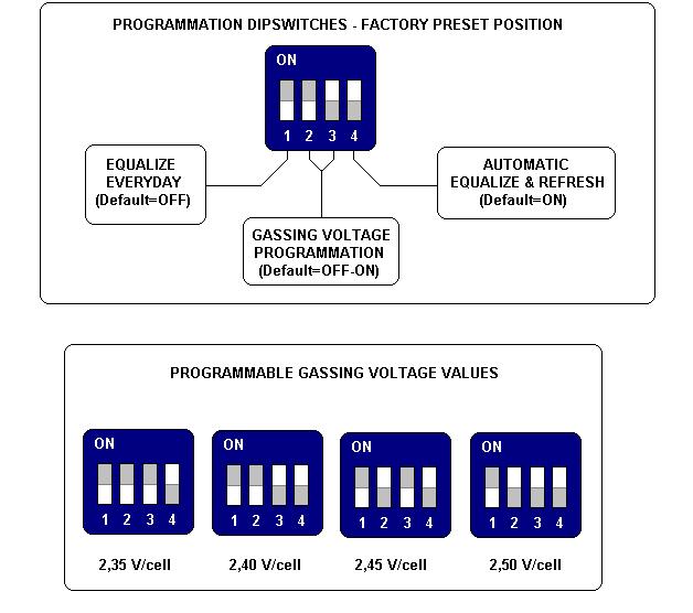
10 _ 4. HOW TO USE THE CHARGER PROGRAMMATION OF THE GASSING POINT ATTENTION! The proper programmation of the gassing point is important for the correct operation of the EAGLETRONIC MTL2 chargers. Only expert users should modify these settings. The possibility to program the gassing point may help the user to adjust the charging curve to the requirements of the battery during all its life. The default value is 2.40 Volt/cell. This value can be modified by moving two dipswitches that are located on the MTL board, near the microprocessor and the black heatsink (see next picture). The dipswitch unit has 4 switches: the two central switches (number 2 and number 3) are used for the programmation of the gassing point. To modify the value, follow these steps: Disconnect the charger from main supply and battery. Locate the dipswitches on the digital electronic board (see next picture). Set the dipswitches according with the following table and pictures. Connect the charger to main supply. Page 10/18

11 _ Page 11/18
12 _ DS #2 DS #3 GASSING POINT V/cell V/cell V/cell V/cell When a battery will be connected to the charger, the programmed gassing voltage will be shown on the display during the startup sequence. BATTERY CONNECTION VOLTAGE CHECK AND AUTOSTART ATTENTION! Eagletronic MTL2 chargers are programmed to execute a complete cycle of charge automatically, however it s recommended to survey the operations when the battery remains connected to the charger for more than 12 hours (example: week-ends). Connect the battery to the charger, using an adequate plug. When the battery is correctly connected, the display turns on and shows the battery voltage. If the battery voltage lower than the minimum threshold of 1,62 V/cell, the charger doesn't start, and the display will show the error message Voltage Low : If the battery voltage is higher than the maximum threshold of 2,60 V/cell, the charger doesn't start, and the display will show the (flashing) error message Voltage High : If the voltage of the battery is between the minimum and maximum thresholds, the charger will wait for 3 seconds before to start charging, while the display will show the programmed gassing voltage. If, during the charge, the voltage of the battery exceeds the maximum threshold of 2,80 V/cell, the charger shuts down automatically, and the errore message Voltage High will appear on the display. Page 12/18
 (Ah); Time of charge. (h) (Hours); During all the charge cycle these parameters are displayed in sequence, as indicated in the picture.")
13 _ CHARGE OPERATION When the charge is started, the digital display will start showing the following parameters: Voltage per cell of the battery (U) (Volt); Charge current; (A) (Ampere); Capacity charged; (C) (Ah); Time of charge. (h) (Hours); During all the charge cycle these parameters are displayed in sequence, as indicated in the picture. The letter (U-A-C-h) indicates which parameter being is displayed. To display the time, the charger uses this format: (HOURS). (MINUTE DECADES) h Examples: Time of charge 3h 30minutes: Displayed 3.3h Time of charge 7h 50minutes: Displayed 7.5h The charge current follows the Wa curve, as described in the norm DIN 41774, while the charge parameters continue to be shown on the digital display. Page 13/18
14 _ When the battery reaches the gassing voltage, the charge continues for one half of the time needed to reach the gassing voltage, with a minimum total time of 30 minutes. Examples: if the battery reaches the gassing voltage in 1 minute, the final charge will continue for 30 minutes. if the battery reaches the gassing voltage in 5 hours, the final charge will continue for 2 hours and 30 minutes. if the battery reaches the gassing voltage in 10 hours, the final charge will continue for 5 hours. If the battery reaches the gassing voltage in 11h59m59s, the final charge will continue for 5h 59m59s (this is the maximum total time allowed before going to Emergency state). These time limits are ok to use the charger with different battery capacities (depending on the time available for the charge, from 8 to 16 hours), and it s not needed to do adjustments on the board. SAFETY TIMER EMERGENCY STOP If the battery doesn't reach the gassing voltage within 12 hours, the charge is terminated by the safety timer, and the display shows the error message Time Error : If this error message appear, it's recommended to call the service for a complete check of the system. The cause if this problem may be a wrong setting of the input voltage: if the input is set to a certain value (for example: 610 V) but the real voltage is lower (for example: 575 V), the charging current will be significantly lower than the nominal value, thus causing a longer time to reach the gassing voltage. AUTOMATIC DATA SAVING If, during the charge or equalization, one or more black-outs of the mains happen, the microprocessor automatically saves all the relevant informations about the state of the charge. While the input power is absent and the battery is connected to the charger, the display will show the message Black Out : When the power supply will be available again, the charger will re-start automatically from the exact point of interruption, and the charge will be normally completed. Page 14/18
15 _ BLOWN FUSE DETECTION If the output fuse is blown or absent, the display will show the message Fuse : This message may appear also if the battery has been left discharged for long time, causing the sulphation process on the plates. AUTOMATIC CHARGE TERMINATION CAUTION! NEVER disconnect the battery while it's being charged. Disconnecting the battery while it's being charged is hazardous for the user and voids the charger warranty. When the charge is complete, the charger shuts down, and the display shows the scrolling message End Elapsed x.x h. The time indicated by the display is the time elapsed after the charge has been terminated. This indication is useful when there are two or more forklift operated with FIFO (First In First Out) rotation: when the user picks up a forklift, he will always chose the one with highest he time elapsed after charge termination. The final values of Voltage/cell, time of charge and capacity charged remain stored in memory. If the red STOP pushbutton is pressed, the display will show these values in sequence. AUTOMATIC SHUTDOWN ON BATTERY DISCONNECTION CAUTION! NEVER disconnect the battery while it's being charged. Disconnecting the battery while it's being charged is hazardous for the user and voids the charger warranty. If the battery is disconnected while the charge is in progress, the EagleTronic MTL2 switches off automatically. Page 15/18
16 _ EQUALIZE & REFRESH MODES ATTENTION! The proper programmation of the equalize & refresh modes is important for the correct operation of the EAGLETRONIC MTL2 chargers. Only expert users should modify these settings. Eagletronic MTL2 chargers have a complete set of programmable equalize & refresh functions: MANUAL EQUALIZE: 4 hours extension of the charge time (selected by user) DAILY EQUALIZE: 4 hours extension of the charge time (everyday) AUTO EQUALIZE & REFRESH: Weekly equalize cycle + long term battery refresh MANUAL EQUALIZE The MANUAL EQUALIZE function is intended for the users that prefer to manage the equalization of the batteries personnally. It will extend the time of the charge cycle by 4 hours, and it can be enabled by pushing the apposite button, located on the right side of the front panel, during the first minutes of charge. The display will add the message Eq. On to the cyclical visualization of the charge parameters, and the charge will proceed normally. Once the manual equalize has been selected, the only way to deselect it is to disconnect and re-connect the battery. DAILY EQUALIZE The DAILY EQUALIZE function will extend all the charge cycles by 4 hours, and it's suitable to recover batteries that are lightly sulphated. It can be enabled by moving the internal DIPSWITCH #1 to position ON (see the description of the programmation dipswitches in the previous paragraphs). The DAILY EQUALIZE function is DISABLED by default. Since the DAILY EQUALIZE is a very intense equalize program and may tend to overcharge the battery, it's recommended to limit it to short periods, then to return to a normal equalize program. It's also recommended to survey the operation of the charger and keep the temperaure of the battery under precise control while the DAILY EQUALIZE function is enabled. Page 16/18
17 _ AUTO EQUALIZE + REFRESH The AUTO EQUALIZE + REFRESH function is totally managed by the MTL2 microcontroller. It can be enabled by moving the internal DIPSWITCH #4 to position ON (see the description of the programmation dipswitches in the previous paragraphs). The AUTOMATIC EQUALIZE + REFRESH is ENABLED by default. If the charge has been completed normally, the charger will add 5 short additional charge cycles of 30 minutes, with 14 hours and 30 minutes interval between each charge. During the time interval between each equalization charge, the display will show the scrolling message: End Elapsed x.x h : When the equalization chargers are in progress, the display will show the scrolling message: equalization charge : followed by the indication of the charge current. REFRESH OPERATION If a battery is not used for a long time (example: seasonal works, holiday periods), it should be kept well charged to avoid a reduction of performance, therefore it's very important to charge the battery before leaving it in stock for more than 24 hours. The self-discharge process makes it harder to keep a battery charged when the time of stocking is longer (weeks or months). The REFRESH function is useful to keep the battery in perfect condition when it's not used for an indefined time. It is sufficient to leave the battery connected to the charger after the charge and the equalization is complete. The Eagletronic MTL2 microprocessor will keep the battery voltage under control and will activate the charger automatically if the voltage drops below a predefined minimum theshold. While the battery is monitored by the charger, the display will show the scrolling message Volt Control : Page 17/18
18 _ If the voltage drops down below the minimum threshold, the charger will give an extra charge cycle to keep the battery in perfect condition, and the display will show the scrolling message: Refresh. Each Refresh charge terminates when the battery voltage reaches a predefined maximum threshold. NOTE: With this voltage controlled refreshing system, the battery will be kept in perfect condition for an undefined time, without any risk of undercharge or overcharge. If the battery is in ideal condition (self-discharge absent) the refresh charge will never be activated. In the opposite case, if the battery is in bad condition and the self-discharge is significant, the refresh charge will be often activated and the battery will be kept charged without problems. les are completed, the charger passes to REFRESH mode. MANUAL CHARGE TERMINATION CAUTION! NEVER disconnect the battery while it's being charged. Disconnecting the battery while it's being charged is hazardous for the user and voids the charger warranty. While the charge is in progress, it's possible to shut down the charger by pressing the red button MANUAL STOP on the front panel. The display will show the message Stop : The final values of Voltage/cell, Time of charge and Capacity Charged remain stored in memory. If the MANUAL STOP button is pressed again, these values will be displayed in sequence. When the charge is terminated manually, the equalization and refresh functions are automatically disabled. Page 18/18
19 !!"! *+' () &'' % % % #% $! #!#! -,,, 6%./ &''01/2(&1301!!, 4+05!!&'05!"!"!
20 !!"! *+' () &'' % % % #% $! #!#!.- - -,% /0 &''1203(&2412!!- 5+16!!&'16!"!"!
21 93! "!! " "# ##, *+ #$%&' # *+ $%&'$%&'$%&'! ())!! - /0 ())%&01*(&2%& 3 45%6 ()%6!"
22 2+!!! )8 63&'4 6 )8 3&'43&'43&'4!5 $%%!! "# $%%&'#()$'*&'+,-&.$%&./!/
23 _ Bassi Bruno elettromeccanica & C. S.n.c. Via Mensa 3/2, S. Maria in Fabriago Lugo (RA) Tel Fax
BATTERY CHARGER AR-D
 BATTERY CHARGER AR-D USER'S MANUAL (THIS PAGE WAS INTENTIONALLY LEFT BLANK) TABLE OF CONTENTS...3...3...3...3...3...3...3 1. Introduction...4 RESPONSIBILITY DISCLAIMER...4 2. Safety instructions and warnings...5
MULTIVOLTAGE PORTABLE BATTERY CHARGER MVM
 _ M MULTIVOLTAGE PORTABLE BATTERY CHARGER MVM User's MANUAL Code: MVM Version: 01-BF Date: OCT 2005 Page 1/10 _ 1. INTRODUCTION Before starting to use your Energic plus MVM battery charger, please take
DISCHARGER-ANALYZER BDX USER'S MANUAL
 BATTERY DISCHARGER-ANALYZER BDX USER'S MANUAL OWM-BDX-261006 Page 1/10 1. INTRODUCTION Before starting to use your BDX battery discharger/analyzer, please take the time to read these instructions carefully.
OWNER S MANUAL AC150 MANUAL TIMER CHARGE CONTROL
 OWNER S MANUAL 193111-091 Issued March 25, 2011 IMPORTANT: Read these instructions before installing, operating, or servicing this system. AC150 MANUAL TIMER CHARGE CONTROL DO NOT DESTROY AMETEK/PRESTOLITE
Service Manual BLACK DIAMOND SERVICE MANUAL. V.160 November
 BLACK DIAMOND SERVICE MANUAL V.160 November 2011 www.montrealchargeur.com www.battelec.ca www.doctorfleet.com Page 1/30 1. SAFETY PRECAUTIONS 1 Before to start using the Black Diamond Charger, read these
OWNER S MANUAL Revised JULY 2, IMPORTANT: Read this manual before installing, operating, or servicing this product.
 OWNER S MANUAL 193111-053 Revised JULY 2, 2003 IMPORTANT: Read this manual before installing, operating, or servicing this product. Power Mate DO NOT DESTROY IMPORTANT: SAVE THIS SAFETY AND INSTRUCTION
OWNER S MANUAL
 OWNER S MANUAL 193111-078 Revised May 13, 2011 IMPORTANT: Read these instructions before installing, operating, or servicing this system. Specifications covered by this manual:. 500882-001. 500883-001
SMC BATTERY CHARGER USER S MANUAL SMC USER S MANUAL
 SMC BATTERY CHARGER SMC 1 INDEX 1 INDEX... 1 2 INTRODUCTION... 2 2.1 INTRODUCTION AND REFERENCES... 2 2.2 GLOSSARY... 2 2.3 DATA LABEL... 2 2.4 HOW TO USE THE USER'S MANUAL... 2 2.5 RESPONSIBILITY DISCLAIMER...
User s Manual. Automatic Switch-Mode Battery Charger
 User s Manual Automatic Switch-Mode Battery Charger IMPORTANT Read, understand, and follow these safety rules and operating instructions before using this battery charger. Only authorized and trained service
OWNER S MANUAL
 OWNER S MANUAL 193111-081 Issued March 14, 2008 IMPORTANT: Read these instructions before installing, operating, or servicing this system. BATTERY-MATE 60 Silicon Diode Ferroresonant Transformer type Battery
QPET, QPETXU Battery Chargers
 C O R P O R A T IO N O P E R A T I N G I N S T R U C T I O N S QPET, QPETXU Battery Chargers INTRODUCTION: The QPET line of chargers are designed for general purpose deep cycle batteries. They are an electronically
QSSE, QSSEX INDUSTRIAL Battery Chargers
 C O R P O R A T IO N O P E R A T I N G I N S T R U C T I O N S QSSE, QSSEX INDUSTRIAL Battery Chargers INTRODUCTION The QSE line are electronically controlled float chargers. The batteries are brought
OWNER S MANUAL
 OWNER S MANUAL Revised October 25, 2006 IMPORTANT: Read these instructions before installing, operating, or servicing this system. ULTRA CHARGE Multiple Circuit Silicon Controlled Rectifier Battery Charger
OWNER S MANUAL
 OWNER S MANUAL 193111-080 Issued March 7, 2008 IMPORTANT: Read these instructions before installing, operating, or servicing this system. BATTERY-MATE 80 Silicon Diode Ferroresonant Transformer type Battery
OWNER S MANUAL ECLIPSE II PLUS Opportunity Battery Charger
 OWNER S MANUAL 193111-096 Issued September 30, 2011 IMPORTANT: Read these instructions before installing, operating, or servicing this system. ECLIPSE II PLUS Opportunity Battery Charger DO NOT DESTROY
OWNER S MANUAL
 OWNER S MANUAL 193111-049 Revised December 10, 2008 IMPORTANT: Read these instructions before installing, operating, or servicing this system. POWER PRO FERRO 100 SERIES CHARGERS Silicon Diode Ferroresonant
innovations in battery charging
 innovations in battery charging AutomaticBatteryCharger forsealed or Valve Regulated Lead-Acid Batteries Model HPX-60 Series OperatingInstructions WARNING CONCERNING THE REMOVAL OF COVER: CAUTION: TO PREVENT
OBAE, OBAEXU, ON BOARD Battery Chargers
 C O R P O R A T IO N O P E R A T I N G I N S T R U C T I O N S OBAE, OBAEXU, ON BOARD Battery Chargers INTRODUCTION: The OBAE line of chargers are designed for the permanent installation on battery powered
ACCUSENSE CHARGE SERIES ON/OFF BOARD FULLY AUTOMATIC BATTERY CHARGER
 ACCUSENSE CHARGE SERIES ON/OFF BOARD FULLY AUTOMATIC BATTERY CHARGER SPECIFICATIONS: *Photo for reference only* Part number 8890439 Mode Select: Selects Battery Type Refer to Section 6. IMPORTANT: READ
MODEL 6010A 6 12 VOLT BATTERY CHARGER ASSOCIATE
 MODEL 600A 6 VOLT BATTERY CHARGER ASSOCIATE IMPORTANT SAFETY INSTRUCTIONS. SAVE THESE INSTRUCTIONS. This manual contains important safety and operating instructions for the battery charger you have purchased.
OWNER S MANUAL
 OWNER S MANUAL 193111-082 Revised June 30, 2010 IMPORTANT: Read these instructions before installing, operating, or servicing this system. POWER STAR SCR Controlled Output Type Battery Charger DO NOT DESTROY
OPERATOR'S MANUAL IMPORTANT SAFETY INSTRUCTIONS
 ASSOCIATED OPERATOR'S MANUAL IMPORTANT SAFETY INSTRUCTIONS MODEL 6366 12 VOLT, 0-20 AMP 4 X 20 BATTERY CHARGER 1. SAVE THESE INSTRUCTIONS. This manual contains important safety and operating instructions
OWNER S MANUAL
 OWNER S MANUAL Issued August 9, 2002 IMPORTANT: Read these instructions before installing, operating, or servicing this system. POWER PRO FERRO 60 SERIES CHARGERS Silicon Diode Ferroresonant Transformer
Art. No. EC-315. Art. No. EC-330. Art. No. EC-340 SWITCH-MODE BATTTERY CHARGER CONTENTS IMPORTANT SAFETY PRECAUTIONS... 2
 SWITCH-MODE BATTTERY CHARGER CONTENTS IMPORTANT SAFETY PRECAUTIONS... 2 DESCRIPTION AND FEATURES... 3 CHARGING STAGES... 4 Art. No. EC-315 Art. No. EC-330 Art. No. EC-340 PROTECTIONS... 5 INSTALLATION...
SERVICE MANUAL. for. Engine-to-Generator FLEXIBLE COUPLING. Part Number used on. Aircraft Ground Power Generator Sets.
 061886 Revised 071389 SERVICE MANUAL for Engine-to-Generator FLEXIBLE COUPLING Part Number 488908 used on Aircraft Ground Power Generator Sets manufactured by HOBART BROTHERS COMPANY Power Systems Group
OBE, OBEXU, ON BOARD Battery Chargers
 C O R P O R A T IO N O P E R A T I N G I N S T R U C T I O N S OBE, OBEXU, ON BOARD Battery Chargers INTRODUCTION: These chargers are designed for the permanent installation on battery powered vehicles
SP6. Automatic Battery Charger. Model
 Model SP6 Automatic Battery Charger OWNERS MANUAL PLEASE SAVE THIS OWNERS MANUAL AND READ BEFORE EACH USE. This manual will explain how to use the charger safely and effectively. Please read and follow
Installation and Operating Instructions. MPPT Solar System Controller ISC3040
 Installation and Operating Instructions MPPT Solar System Controller ISC3040 ABOUT THIS MANUAL These operating instructions come with the product and should be kept with it as a reference to all user s
LESTRONIC II BATTERY CHARGER MODEL 07210
 LESTRONIC II BATTERY CHARGER MODEL 07210 PLEASE SAVE THESE IMPORTANT SAFETY AND OPERATING INSTRUCTIONS For correct operation of the equipment, it is important to read and be familiar with this entire manual
8-STAGE AUTOMATIC BATTERY CHARGER MCU CONTROLLED - HIGH FREQUENCY SWITCHMODE MODELS: KACHG1207, KACHG1212, KACHG1220, KACHG2410. Instruction Manual
 8-STAGE AUTOMATIC BATTERY CHARGER MCU CONTROLLED - HIGH FREQUENCY SWITCHMODE MODELS: KACHG1207, KACHG1212, KACHG1220, KACHG2410 Instruction Manual Please read user manual carefully before use. WARNING
OWNER S MANUAL AC1000
 OWNER S MANUAL 193111-084 Revised July 19, 2010 IMPORTANT: Read these instructions before installing, operating, or servicing this system. AC1000 CHARGE CONTROL DO NOT DESTROY AMETEK/PRESTOLITE POWER,
Models: SP3, SPSS3 Automatic Battery Charger
 OWNERS MANUAL Models: SP3, SPSS3 Automatic Battery Charger PLEASE SAVE THIS OWNERS MANUAL AND READ BEFORE EACH USE. This manual will explain how to use the charger safely and effectively. Please read and
STEP-BY-STEP INSTALLATION GUIDE
 Battery Backup System STEP-BY-STEP INSTALLATION GUIDE Operating Instructions & Parts Manual ESP25 Please read and save these instructions. Read carefully before attempting to assemble, install, operate
OPERATING INSTRUCTIONS. Note: 6V Charging. Requires Manual Shut Off.
 Requires Manual Shut Off. 6 / 2 AMP,, DUAL RATE BATTER TTERY CHARGER 45005 OPERATING INSTRUCTIONS E224783 E224783 Note: 6V Charging Due to continuing improvements, actual product may differ slightly from
Battery Chargers Sealed or Valve Regulated Lead Acid Batteries Models: PSC A AND PSC A
 Battery Chargers Sealed or Valve Regulated Lead Acid Batteries Models: PSC-122000A AND PSC-241000A Operating Instructions WARNING CONCERNING THE REMOVAL OF COVER: CAUTION: TO PREVENT THE RISK OF ELECTRIC
12 VOLT 30 AMP DIGITAL SOLAR CHARGE CONTROLLER
 12 VOLT 30 AMP DIGITAL SOLAR CHARGE CONTROLLER User s Manual Congratulations on your Coleman solar product purchase. This product is designed to the highest technical specifications and standards. It will
24 VOLT AUTOMATIC BATTERY CHARGER PART NO
 24 VOLT AUTOMATIC BATTERY CHARGER PART NO. 957732 AC Input: DC Output: Battery Type: Specifications 230 volts, 50 hertz, 3.5 amps, single-phase 24 volts, 20 amps initially tapering to 6 amps 24 volt, 12
3000W HF/PFC Battery Charger
 3000W HF/PFC Battery Charger Description Advanced high frequency switching design with 92% typical efficiency Fully sealed enclosure providing improved reliability in demanding environments > 0.98 Power
FULLY AUTOMATIC SCR BATTERY CHARGER
 *35589* FULLY AUTOMATIC SCR BATTERY CHARGER FEATURES Microprocessor controlled charge circuit monitors battery state of charge and automatically turns charger off when the batteries reach full charge.
24 VOLT DUAL MODE WHEELCHAIR BATTERY CHARGER MODEL TYPE 24EL8 E&J PRODUCT NO
 24 VOLT DUAL MODE WHEELCHAIR BATTERY CHARGER MODEL 12630 TYPE 24EL8 E&J PRODUCT NO. 90483465 Specifications AC Supply: 120 volts, 60 Hertz, single-phase, 4 amps maximum DC Output: 24 volts, 8 amps, tapering
Deep Cycle Battery Safety. First. Battery Handling, Maintenance & Test Procedures
 Deep Cycle Battery Safety. First. Battery Handling, Maintenance & Test Procedures Crown deep cycle batteries employ a low-maintenance design. They do require periodic maintenance and effective charging
Installation and Operating Instructions. Solar System Controller ISC3030
 Installation and Operating Instructions Solar System Controller ISC3030 ABOUT THIS MANUAL These operating instructions come with the product and should be kept with it as a reference to all user s of the
PFC W HF/PFC Battery Charger
 PFC 5000 5000W HF/PFC Battery Charger Description Advanced high frequency switching design with 92% typical efficiency Fully sealed enclosure providing improved reliability in demanding environments >
PUMP PLUS 2000 PLC MODEL #: PP AUTOMATIC DUAL OUTPUT BATTERY CHARGER INSTRUCTION MANUAL
 INSTRUCTION MANUAL PUMP PLUS 2000 PLC AUTOMATIC DUAL OUTPUT BATTERY CHARGER Supplied with Dual Bar Graph Display MODEL #: 091-237-12-PP INPUT: 120 Volt, 60 Hz, 3.5 Amps OUTPUT BATTERY 1 and 2: 15 or 18
MINE CHARGER INSTALLATION AND OPERATION MANUAL MODEL NUMBERS: MSP MSQ MSR MSS
 MINE CHARGER INSTALLATION AND OPERATION MANUAL MODEL NUMBERS: MSP MSQ MSR MSS Sec# Table of Contents Pg# 1 INSTALLATION 1.1 Receiving 1 1.2 Location 1 1.3 Line Voltage Adjustments 2 1.4 A.C. Service Requirements
Chargestar P24 / P32 Battery Charger Startmaster P300 Starter / Charger
 Please dispose of packaging for the product in a responsible manner. It is suitable for recycling. Help to protect the environment, take the packaging to the local amenity tip and place into the appropriate
Automatic Battery Charger Switching mode with Micro-controlled Input: Vac / Output: 12Volt DC
 Automatic Battery Charger Switching mode with Micro-controlled Input:100-140Vac / Output: 12Volt DC User s Manual and Important Safety Information Model: #20085 (SW121080-06) FEATURES Congratulations on
MASTERsine Inverter PXA Series Installation Guide
 Backup Power System Expert TM MASTERsine Inverter PXA Series Installation Guide Important Safety Instructions IMPORTANT: Read and save this Installation Guide for future reference. This chapter contains
12 amp RMS Battery Charger
 12 amp RMS Battery Charger 83-5000-12 If faults cannot be remedied, contact the Helpline on 020 8391 6767 helpline@hilka.co.uk Manufactured under license by Hilka Pro Imports GUARANTEE This product is
IMPORTANT SAFETY INSTRUCTIONS
 1163714 1.5 AMP 12VOLT TRICKLE 1.5 AUTOMATIC AMP AUTOMATIC TRICKLE 1.5 AMP AUTOMATIC 12V12VOLT BATTERY CHARGER IMPORTANT SAFETY INSTRUCTIONS 1. SAVE THESE INSTRUCTIONS This product offers a wide range
User Manual Solar Charge Controller 3KW
 User Manual Solar Charge Controller 3KW Version: 1.3 CONTENTS 1 ABOUT THIS MANUAL... 1 1.1 Purpose... 1 1.2 Scope... 1 1.3 SAFETY INSTRUCTIONS... 1 2 INTRODUCTION... 2 2.1 Features... 2 2.2 Product Overview...
innovations in battery charging
 innovations in battery charging AutomaticBattery Charger for Sealed or Valve Regulated Lead-AcidBatteries Model HPX-10 Series OperatingInstructions POWER/FLOAT FAST CHARGE FAULT (shorted or reversed output
Model: SE-4020-CA Automatic Battery Charger
 OWNERS MANUAL Model: SE-4020-CA Automatic Battery Charger PLEASE SAVE THIS OWNERS MANUAL AND READ BEFORE EACH USE. This manual will explain how to use the battery charger safely and effectively. Please
ST Charger. Industrial Battery Charger
 ST Charger Industrial Battery Charger Installation and Operation Manual ST_13 Table of Contents Pg# 1.0 INSTALLATION 1 1.1 Receiving 1 1.2 Location 1 1.3 Line Voltage 1 1.4 A.C. Service Requirements 2
OWNER S MANUAL
 OWNER S MANUAL Revised February 2, 2011 IMPORTANT: Read these instructions before installing, operating, or servicing this system. SCR2000 CHARGE CONTROL DO NOT DESTROY AMETEK/PRESTOLITE POWER, TROY, OHIO
5 IN 1 JUMP START OPERATION & MAINTENANCE INSTRUCTIONS MODEL NO: JS5IN1 PART NO: LS0810
 5 IN 1 JUMP START MODEL NO: JS5IN1 PART NO: 6240005 OPERATION & MAINTENANCE INSTRUCTIONS LS0810 INTRODUCTION Thank you for purchasing this CLARKE product. Before attempting to use this product, please
12V/25A BATTERY CHARGER MAINTAINER / JUMPSTARTER
 12V/25A BATTERY CHARGER MAINTAINER / JUMPSTARTER OWNER S MANUAL Read carefully and understand all ASSEMBLY AND OPERATION INSTRUCTIONS before operating. Failure to follow the safety rules and other basic
Automatic taper of charge rate for superior battery life through good equalization of cells and low water use rate.
 FEATURES Automatic taper of charge rate for superior battery life through good equalization of cells and low water use rate. Silicon diodes with inherent surge protection operated at a conservative percentage
8 Step Fully Automatic Intelligent BATTERY CHARGER 12V 5A USER S MANUAL. Charges & Maintains. Flooded (WET), MF, VRLA, AGM, GEL & Calcium batteries
, MF, VRLA, AGM, GEL & Calcium batteries") 8 Step Fully Automatic Intelligent BATTERY CHARGER 12V 5A Charges & Maintains Flooded (WET), MF, VRLA, AGM, GEL & Calcium batteries USER S MANUAL 5 User s Manual And Guide To Professional Battery Charging
8 Step Fully Automatic Intelligent BATTERY CHARGER 12V 5A Charges & Maintains Flooded (WET), MF, VRLA, AGM, GEL & Calcium batteries USER S MANUAL 5 User s Manual And Guide To Professional Battery Charging
Compact Sine Inverter
 Compact Sine Inverter Instructions for installation & use Applies to the following models: Output power: 700watt, 1000 watt, 1500watt, 2000 watt & 3000 watts Output voltage: and output, 50Hz & 60Hz Output
PUMP PLUS 1000 PLC MODEL #: PP AUTOMATIC SINGLE OUTPUT BATTERY CHARGER INSTRUCTION MANUAL
 INSTRUCTION MANUAL PUMP PLUS 1000 PLC AUTOMATIC SINGLE OUTPUT BATTERY CHARGER Unit supplied with one of these displays MODEL #: 091-215-12-PP INPUT: 120 Volt, 60 Hz, 3.5 Amps OUTPUT BATTERY 1 and 2: 15
MP V 8A Electronic Smart Charger. Instruction and Information Manual
 MP7428 12V 8A Electronic Smart Charger Instruction and Information Manual In order to ensure correct and safe usage of your battery charger, you should read these instructions carefully. Please retain
MODEL ELC-12/60-D BATTERY CHARGER
 *32198* NATIONAL RAILWAY SUPPLY Installing, Operating and Service Instructions for the 12/60 Solid State Charger MODEL ELC-12/60-D BATTERY CHARGER PLEASE SAVE THESE IMPORTANT SAFETY AND OPERATING INSTRUCTIONS
Installation and Operating Instructions. Solar System Controller ISC3020
 Installation and Operating Instructions Solar System Controller ISC3020 ABOUT THIS MANUAL These operating instructions come with the product and should be kept with it as a reference to all user s of
Monicon Instruments Co., Ltd. CHR-1285/2485 CHR-1285/2485 BATTERY CHARGER
 CHR-1285/2485 BATTERY CHARGER TEL:886-4-2238-0698 FAX:886-4-2238-0891 Web Site:http://www.monicon.com.tw E-mail:sales@monicon.com.tw Copyright 2007 Monicon Instruments Co., Ltd. All right reserved. Contents
Battery Chargers Sealed or Valve Regulated Lead Acid Batteries Model: PSC A
 Battery Chargers Sealed or Valve Regulated Lead Acid Batteries Model: PSC-124000A OPERATING PROCEDURES AND SAFETY INSTRUCTIONS CAUTION: TO PREVENT THE RISK OF ELECTRIC SHOCK, DO NOT REMOVE COVER NO USER
BATTERY BOOSTER/CHARGER MODEL NO: DIGICAR 900
 BATTERY BOOSTER/CHARGER MODEL NO: DIGICAR 900 PART NO: 6261205 OPERATION & MAINTENANCE INSTRUCTIONS LS0715 INTRODUCTION Thank you for purchasing this CLARKE Battery booster / charger which is suitable
COLT CELL BATTERY CHARGER Installation and Operating Instructions
 COLT CELL BATTERY CHARGER Installation and Operating Instructions INSTALLATION All COLT chargers are for indoor use only. All COLT chargers are designed for installation into the battery tray. Charging
INTELLIGENT BATTERY CHARGER/MAINTAINER
 INTELLIGENT BATTERY CHARGER/MAINTAINER OWNER S MANUAL Read carefully and understand all ASSEMBLY AND OPERATION INSTRUCTIONS before operating. Failure to follow the safety rules and other basic safety precautions
OWNER S MANUAL AC1000
 OWNER S MANUAL 193111-030 Revised October 23, 2002 IMPORTANT: Read these instructions before installing, operating, or servicing this system. AC1000 CHARGE CONTROL DO NOT DESTROY AMETEK/PRESTOLITE POWER,
INSTALLATION AND OPERATING INSTRUCTIONS FOR FLOODED TUBULAR-HP MOTIVE POWER BATTERIES
 PLEASE READ BEFORE PLACING BATTERIES IN SERVICE THESE INSTRUCTIONS TO BE SHIPPED WITH BATTERY AND TO BE DELIVERED TO USER INSTALLATION AND OPERATING INSTRUCTIONS FOR FLOODED TUBULAR-HP MOTIVE POWER BATTERIES
Safety, Installation And Operating Instructions For The Following Battery Charger Models: i2412, i3612, i4809, i2425, i3625, and i4818
 Safety, Installation And Operating Instructions For The Following Battery Charger Models: i2412, i3612, i4809, i2425, i3625, and i4818 IMPORTANT NOTICE: Please save and read these safety, operating and
OWNER S MANUAL PORTABLE POWER COMPACT & ROBUST
 52731 18 AMP-HOUR 12 VOLT OVERHEAT PROTECTION JUMP START OWNER S MANUAL PORTABLE POWER COMPACT & ROBUST 18 Amp-Hour, 12 Volt Wall charger 6-gauge booster cable Built in ultra-bright LED work light Safety
AUTO CHARGE DUAL MODEL #: AUTOMATIC DUAL OUTPUT BATTERY CHARGER INSTRUCTION MANUAL. Ph: Fax:
 INSTRUCTION MANUAL AUTO CHARGE DUAL AUTOMATIC DUAL OUTPUT BATTERY CHARGER MODEL #: 091-145-12 INPUT: 120 Volt, 50/60 Hz, 3.5 Amps OUTPUT BAT 1: 10 Amps OUTPUT BAT 2: 10 Amps File: IM_091-145-12_revb.indd
AUTO CHARGE 4000 MODEL #: LOW PROFILE CHARGER AUTOMATIC DUAL OUTPUT BATTERY CHARGER INSTRUCTION MANUAL
 INSTRUCTION MANUAL AUTO CHARGE 4000 LOW PROFILE CHARGER AUTOMATIC DUAL OUTPUT BATTERY CHARGER Unit supplied with this display MODEL #: 091-89-12 INPUT: 120 Volt, 50/60 Hz, 5 Amps OUTPUT: 45 Amps File:
IMPORTANT SAFETY INSTRUCTIONS IMPORTANT: READ AND SAVE THIS SAFETY AND INSTRUCTION MANUAL. KEEP IT WITH OR NEAR CHARGER AT ALL TIMES.
 IMPORTANT SAFETY INSTRUCTIONS IMPORTANT: READ AND SAVE THIS SAFETY AND INSTRUCTION MANUAL. KEEP IT WITH OR NEAR CHARGER AT ALL TIMES. SPECIFICATIONS: For technical assistance, call your Dealer with the
"ELECTRICAL SAFETY IN THE LABORATORY"
 MAJOR PROGRAM POINTS "ELECTRICAL SAFETY IN THE LABORATORY" Part of the "LABORATORY SAFETY SERIES" Quality Safety and Health Products, for Today...and Tomorrow Outline of Major Points Covered in the "Electrical
A2P Single Phase Automatic Industrial Battery Charger
 A2P Single Phase Automatic Industrial Battery Charger Featuring 205B Konrad Cres., Markham, ON, L3R 8T9 www.chargers.ca Building Canada s toughest battery chargers for over a century. Congratulations on
SOS SERIES SOS1 SOS2. Spares On Site Battery Cabinet Installation Guide rEV3
 Atlantic Battery Systems 1065 Market Street Paterson, NJ 07513 Phone: (800) 875-0073 Fax: (973) 523-2344 sales@atbatsys.com www.atbatsys.com SOS1 SOS2 SOS SERIES Spares On Site Battery Cabinet Installation
12V 1 AMP (1000 ma) Automatic Battery Charger & Maintainer
 Automatic Battery Charger & Maintainer") 12V 1 AMP (1000 ma) Automatic Battery Charger & Maintainer For lead-acid batteries THIS MANUAL CONTAINS IMPORTANT SAFETY AND OPERATING INSTRUCTIONS FOR 12V BATTERY CHARGER: YUA1201000 / INT1201000 KEEP
12V 1 AMP (1000 ma) Automatic Battery Charger & Maintainer For lead-acid batteries THIS MANUAL CONTAINS IMPORTANT SAFETY AND OPERATING INSTRUCTIONS FOR 12V BATTERY CHARGER: YUA1201000 / INT1201000 KEEP
JUMP STARTER OPERATION & MAINTENANCE INSTRUCTIONS MODEL NO: JSM350 PART NO: ORIGINAL INSTRUCTIONS LS1117-ISS 1
 JUMP STARTER MODEL NO: JSM350 PART NO: 6239010 OPERATION & MAINTENANCE INSTRUCTIONS ORIGINAL INSTRUCTIONS LS1117-ISS 1 INTRODUCTION Thank you for purchasing this CLARKE product. Please read this manual
Manual. Curtis Model 1625 Battery Charger. Curtis Instruments, Inc. 200 Kisco Avenue Mt. Kisco, NY
 Manual Curtis Model 1625 Battery Charger Curtis Instruments, Inc. 200 Kisco Avenue Mt. Kisco, NY 10549 www.curtisinstruments.com Read Instructions Carefully! Specifications are subject to change without
Pro Booster 802Li. Please read and fully understand the instructions in this manual before operation. Keep this manual safe for future reference.
 Please dispose of packaging for the product in a responsible manner. It is suitable for recycling. Help to protect the environment, take the packaging to the local amenity tip and place into the appropriate
Sentry Battery Charger. Installation and Operations Manual Section 75
 Sentry Battery Charger Installation and Operations Manual 00-02-0616 03-03-08 Section 75 In order to consistently bring you the highest quality, full featured products, we reserve the right to change our
ENGLISH SAFETY INSTRUCTIONS. Recommendations for safe operation. Operator safety. General warnings
 Safety and use instructions LifeSpeed iq TM - 3-phase chargers ENGLISH SAFETY INSTRUCTIONS GOALS OF THIS MANUAL This manual is aimed at any authorized personnel wanting to use a 3-phase LifeSpeed iq TM
A39 UNIVERSAL SCR CHARGER
 A39 UNIVERSAL SCR CHARGER ECN/DATE CPN35971 21681 01/18 16816-6/05 15349-03 05/02 14575 02/01 14268 10/00 10400 9/96 106 BRADROCK DRIVE DES PLAINES, IL. 60018-1967 (847) 299-1188 FAX: (847) 299-3061 ISSUE
12V 160W Folding Portable Solar Panel Kit KDSLR160PNLA User Manual
 12V 160W Folding Portable Solar Panel Kit KDSLR160PNLA User Manual Table of Contents Product Features... 1 Product Components... 2 Product Specifications... 2 LED Indicators... 3 Safety Precautions...
Battery Chargers Sealed or Valve Regulated Lead Acid Batteries Model: PSC AP
 Battery Chargers Sealed or Valve Regulated Lead Acid Batteries Model: PSC-124000AP OPERATING PROCEDURES AND SAFETY INSTRUCTIONS CAUTION: TO PREVENT THE RISK OF ELECTRIC SHOCK, DO NOT REMOVE COVER NO USER
LS/ CCS. Constant Current Charger
 LS/ CCS Constant Current Charger Installation and Operation Manual CC_13 1 INDEX Page Section Description 3 - Safety Instructions 4 1.0 Installation 4 1.1 Receiving 4 1.2 Location 4 1.3 Line Voltage Adjustments
GENERALITIES TECHNICAL FEATURES
 GENERALITIES This device is a traditional three-phases battery charger, with a power supply of 230Vac or 400Vac. The battery charger is a WA charge cycle type, which ensures a decrease of the current and
Section 650 Page 45 M9208G rev.d INDUSTRIAL BATTERY CHARGER OWNER'S MANUAL INDUSTRIAL BATTERY CHARGER
 Section 650 Page 45 M9208G rev.d INDUSTRIAL BATTERY CHARGER OWNER'S MANUAL INDUSTRIAL BATTERY CHARGER TABLE OF CONTENTS PAGE GENERAL INFORMATION 1 Safety 1 Receipt & Installation 1 Operation 2 Service
Battery charger , A, B
 Battery charger 420.093.050, 420.093.050.A, 420.093.050.B Battery charger 420.093.050, 420.093.050.A, 420.093.050.B englisch 12.09 2009 AUDI AG AUDI AG works continuously to develop and further improve
Operator Manual. The most important component is you. This operator manual. has information for. all models of series. B plus some options and
 Operator Manual This operator manual has information for all models of series B plus some options and accessories. Some of the illustrations and information may not apply to your truck. The most important
CONGRATULATIONS ON YOUR PURCHASE OF YOUR THUNDER BATTERY CHARGER! For your personal safety read, understand and follow the information provided in
 CONGRATULATIONS ON YOUR PURCHASE OF YOUR THUNDER BATTERY CHARGER! For your personal safety read, understand and follow the information provided in this instruction manual & on the battery charger. This
Today, we re going to talk about battery safety. We ll discuss all the key issues associated with using batteries safely, including battery hazards,
 Today, we re going to talk about battery safety. We ll discuss all the key issues associated with using batteries safely, including battery hazards, battery charging, and battery maintenance. Although
Installation and Operating Instructions. Solar System Controller ISC1000
 Installation and Operating Instructions Solar System Controller ISC1000 About this manual These operating instructions come with the product and shall be kept along it for all the life of the product
O P E R A T I N G I N S T R U C T I O N S
 O P E R A T I N G I N S T R U C T I O N S Select-A-Charge Battery Chargers models: SCP, SCPX, SCS, SCSX, SCX For Industrial Use: Designed for gel, wet cell, AGM, and Lithium Ion batteries (Lithium ion
AUTO CHARGE 12 HO MODEL #: MODEL #: MODEL #: AUTOMATIC SINGLE OUTPUT BATTERY CHARGER INSTRUCTION MANUAL
 INSTRUCTION MANUAL AUTO CHARGE 12 HO AUTOMATIC SINGLE OUTPUT BATTERY CHARGER MODEL #: 091-170-6 MODEL #: 091-170-12 MODEL #: 091-170-24 File: IM_091-170-xx_revd.indd Rev: D Revised By: MFG Date: 10-23-2013
MODEL 6017 OPERATOR'S MANUAL
 MODEL 6017 OPERATOR'S MANUAL ASSOCIATE D IMPORTANT SAFETY INSTRUCTIONS 1. SAVE THESE INSTRUCTIONS. This manual contains important safety and operating instructions for the battery charger you have purchased.
Safety Training Topic ELECTRICAL SAFETY
 Safety Training Topic Purpose of Meeting To remind workers that electrical hazards can result in a serious injury. To reinforce electrical safety rules. To consider ways to protect yourself from electrical