TX90 Isolated Online UPS
|
|
|
- Erica Jackson
- 6 years ago
- Views:
Transcription
1 TX90 Isolated Online UPS 1000VA, 2000VA, 3000VA, 5000VA Models User & Installation Manual All rights reserved. (Rev 2/29/16)
2 Table of Contents Important Safety Warning...4 Transportation...4 Preparation...4 Installation...4 Operation...4 Installation And Setup...6 Rear Panel View...6 Setup the UPS...8 Operations...10 Button Operation...10 LCD Panel...11 Audible Alarm...12 LCD Display Wordings Index...12 UPS Setting...13 Operating Mode Description...17 Faults Reference Code...18 Warning Indicator...18 Troubleshooting...19 Storage And Maintenance Operation...21 Specifications...22 Obtaining Service...23 Xtreme Power Conversion Limited Warranty...24 Xtreme Power Conversion Load Protection Policy...25 Page 2
3 Important Safety Warning Please comply with all warnings and operating instructions in this manual strictly. Save this manual properly and read carefully the following instructions before installing the unit. Do not operate this unit before reading through all safety information and operating instructions carefully. Transportation Please transport the UPS system only in the original package to protect against shock and impact. Preparation Condensation may occur if the UPS system is moved directly from cold to warm environment. The UPS system must be absolutely dry before being installed. Please allow at least two hours for the UPS system to acclimate the environment. o Do not install the UPS system near water or in moist environments. Do not install the UPS system where it would be exposed to direct sunlight or near heater. Do not block ventilation holes in the UPS housing. Installation Do not connect appliances or devices which would overload the UPS system to the UPS output sockets. o Place cables in such a way that no one can step on or trip over them. o The UPS can be operated by any individuals with no previous experience. Connect the UPS system only to an earthed shockproof outlet which must be easily accessible and close to the UPS system. Please use only VDE-tested, CE-marked mains cable (e.g. the mains cable of your computer) to connect the UPS system to the building wiring outlet (shockproof outlet). Please use only VDE-tested, CE-marked power cables to connect the loads to the UPS system. When installing the equipment, it should ensure that the sum of the leakage current of the UPS and the connected devices does not exceed 3.5mA. Operation Do not disconnect the mains cable on the UPS system or the building wiring outlet (shockproof socket outlet) during operations since this would cancel the protective earthing of the UPS system and of all connected loads. The UPS system features its own, internal current source (batteries). The UPS output sockets or output terminals block may be electrically live even if the UPS system is not connected to the building wiring outlet. o In order to fully disconnect the UPS system, first press the OFF/Enter button to disconnect the mains. o Prevent no fluids or other foreign objects from inside of the UPS system. Maintenance, Service, and Faults The UPS system operates with hazardous voltages. Repairs may be carried out only by qualified maintenance personnel. Caution - risk of electric shock. Even after the unit is disconnected from the mains (building wiring outlet), components inside the UPS system are still connected to the battery and electrically live and dangerous. Before carrying out any kind of service and/or maintenance, disconnect the batteries and verify that no Page 3
4 current is present and no hazardous voltage exists in the terminals of high capability capacitor such as BUS-capacitors. Only persons are adequately familiar with batteries and with the required precautionary measures may replace batteries and supervise operations. Unauthorized persons must be kept well away from the batteries. Caution - risk of electric shock. The battery circuit is not isolated from the input voltage. Hazardous voltages may occur between the battery terminals and the ground. Before touching, please verify that no voltage is present! Batteries may cause electric shock and have a high short-circuit current. Please take the precautionary measures specified below and any other measures necessary when working with batteries: o Remove wristwatches, rings and other metal objects o Use only tools with insulated grips and handles. When changing batteries, install the same number and same type of batteries. Do not attempt to dispose of batteries by burning them. This could cause battery explosion. Do not open or destroy batteries. Escaping electrolyte can cause injury to the skin and eyes. It may be toxic. Please replace the fuse only with the same type and amperage in order to avoid fire hazards. Do not dismantle the UPS system. Page 4


5 Installation And Setup Note: Before installation, please inspect the unit. Be sure that nothing inside the package is damaged. Please keep the original package in a safe place for future use. Rear Panel View TX TX90i-1000 TX TX90i-2000 Page 5
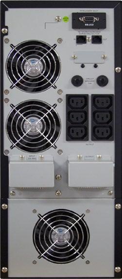
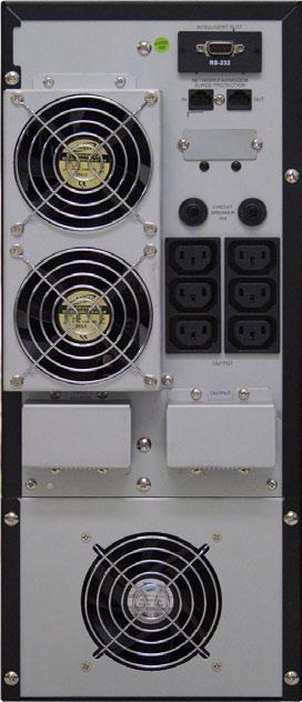
6 TX TX90i-3000 TX90i-5000 Page 6
7 Setup the UPS Step 1: UPS input connection Plug the UPS into a two-pole, three-wire, grounded receptacle only. Avoid using extension cords (The long run model should be connected well the proper capacity of battery with the ups). Step 2: UPS output connection Simply plug devices to output sockets. During power failure, UPS will provide power to connected devices. Step 3: Communication connection RS-232 Port Intelligent Slot To allow for unattended UPS shutdown/start-up and status monitoring, connect the communication cable one end to the RS-232 port and the other to the communication port of your PC. With the monitoring software installed, you can schedule UPS shutdown/start-up and monitor UPS status through PC. 1kVA, 2kVA, 3kVA, 5kVA models are equipped with intelligent slot perfect for SNMP, RS-232, USB or Relay/AS400 card. When installing with these communication card in the UPS, it will provide advanced communication and monitoring options. Step 1: Step 2: Step 3: Remove cover of intelligent slot. Insert communication card into the slot Screw card tightly and complete installation. Step 4: Network connection Connect a single modem/phone/fax line into surge-protected IN outlet on the back panel of the UPS unit. Connect from OUT outlet to the equipment with another modem/fax/phone line cable. Page 7

8 Step 5: Turn on the UPS Press the ON/Mute button on the front panel for two seconds to power on the UPS. Note: The battery charges fully during the first five hours of normal operation. Do not expect full battery run capability during this initial charge period. Step 6: Install software For optimal computer system protection, install UPS monitoring software to fully configure UPS shutdown. You may insert provided CD into CD-ROM to install the monitoring software. If not, please follow steps below to download and install monitoring software from the internet: 1. Go to the website 2. Click ViewPower software icon and then choose your required OS to download the software. 3. Follow the on-screen instructions to install the software. 4. When your computer restarts, the monitoring software will appear as an orange plug icon located in the system tray, near the clock. Step 7: External battery connection Follow the below chart to make external battery connection. To external battery To external battery Step 8: External battery capacity configuration in software To calculate accurate backup time of external batteries, it s necessary to configure battery numbers in software. The standard calculated capacity for one battery is 9Ah. If connecting to 100Ah batteries, then it s equal to 11 in parallel (100Ah / 9Ah 11 sets). Page 8
9 Operations Button Operation Button ON/Mute Button OFF/Enter Button Select Button ON/Mute + Select Button ON/Mute + Select Button Function Turn on the UPS: Press and hold ON/Mute button for at least 2 seconds to turn on the UPS. Mute the alarm: After the UPS is turned on in battery mode, press and hold this button for at least 5 seconds to disable or enable the alarm system. But it s not applied to the situations when warnings or errors occur. Up key: Press this button to display previous selection in UPS setting mode. Switch to UPS self-test mode: Press ON/Mute buttons simultaneously for 5 seconds to enter UPS self-testing while in AC mode or converter mode. Turn off the UPS: Press and hold this button at least 2 seconds to turn off the UPS in battery mode. UPS will be in standby mode under power normal or transfer to Bypass mode if the Bypass enable setting by pressing this button. Confirm selection key: Press this button to confirm selection in UPS setting mode. Switch LCD message: Press this button to change the LCD message for input voltage, input frequency, battery voltage, output voltage and output frequency. It will return back to default display when pausing for 10 seconds. Setting mode: Press and hold this button for 5 seconds to enter UPS setting mode when UPS is in standby mode or bypass mode. Down key: Press this button to display next selection in UPS setting mode. Switch to bypass mode: When the main power is normal, press ON/Mute and Select buttons simultaneously for 5 seconds. Then UPS will enter to bypass mode. This action will be ineffective when the input voltage is out of acceptable range. Switch to UPS self-test mode: Press ON/Mute and OFF/Enter buttons Simultaneously for 5 seconds to enter UPS self-testing while in AC mode or converter mode Page 9

10 LCD Panel Display Backup time information Function Indicates the backup time in pie chart. Fault information Indicates the backup time in numbers. H: hours, M: minute, S: second Indicates that the warning and fault occurs. Mute operation Indicates the warning and fault codes, and the codes are listed in details in 3-5 section. Indicates that the UPS alarm is disabled. Output & Battery voltage information Indicates the output voltage, frequency or battery voltage. Vac: output voltage, Vdc: battery voltage, Hz: frequency Load information Indicates the load level by 0-25%, 26-50%, 51-75%, and %. Indicates overload. Indicates the load or the UPS output is short circuit. Mode operation information Indicates the UPS connects to the mains. Page 10
11 Indicates the battery is working. Indicates the bypass circuit is working. Indicates the Inverter circuit is working. Indicates the output is working. Audible Alarm Battery Mode Low Battery Overload Fault Bypass Mode Sounding every 4 seconds Sounding every second Sounding twice every second Continuously sounding Sounding every 10 seconds LCD Display Wordings Index Abbreviation Display content Meaning ENA DIS ESC HLS LLS BAT CF TP CH Enable Disable Escape High loss Low loss Battery Converter Temperature Charger Page 11
12 UPS Setting Parameter 1 There are three parameters to set up the UPS. Parameter 2 Parameter 3 Parameter 1: It s for program alternatives. There are 6 programs to set up. Refer to below table. Parameter 2 and Parameter 3 are the setting options or values for each program. 01: Output voltage setting Interface Setting For 208/220/230/240 VAC models, you may choose the following output voltage:(default 230Vac/120Vac) 208: presents output voltage is 208Vac 220: presents output voltage is 220Vac 230: presents output voltage is 230Vac 240: presents output voltage is 240Vac For 110/115/120/127 VAC models, you may choose the following output voltage: 110: presents output voltage is 110Vac 115: presents output voltage is 115Vac 120: presents output voltage is 120Vac 127: presents output voltage is 127Vac Page 12
13 02: Input voltage acceptable range setting Interface 03: ECO enable/disable Interface Setting Press the Down key or Up key to set the acceptable high voltage point and acceptable low voltage point of the input: (Default HLS:144V/288V;LLS:88V/176V) HLS: High loss voltage in Line mode For Vout 208/220/230/240 VAC models, the setting range is from 260V to 288V(half of the setting voltage in LV mains) For Vout 110/115/120/127 VAC models, the setting range is from 130V to 144V (twice of the setting voltage in HV mains) LLS: Low loss voltage in Line mode For Vout 208/220/230/240 VAC models, the setting range is from 176V to 190V(half of the setting voltage in LV mains) For Vout 110/115/120/127 VAC models, the setting range is from 88V to 95V(twice of the setting voltage in HV mains) Setting ENA: ECO mode enable (Default DIS) DIS: ECO mode disable 04: ECO voltage range setting Interface Setting Press the Down key or Up key to set the acceptable high voltage point and acceptable low voltage point: HLS: High loss voltage in ECO mode For 208/220/230/240 VAC models, the setting range is from 7V to 24V of the nominal output voltage For 110/115/120/127 VAC models, the setting range is from 3V to 12V of the nominal output voltage. LLS: Low loss voltage in ECO mode For 208/220/230/240 VAC models, the setting range is from -7V to -24V of the nominal output voltage For 110/115/120/127 VAC models, the setting range is from -3V to -12V of the nominal output voltage. Page 13
14 05: Bypass mode enable/disable Interface Setting ENA: Bypass mode enable (Default DIS) DIS: Bypass mode disable 06: Bypass voltage range setting Interface Setting Press the Down key or Up key to set the acceptable high voltage point and acceptable low voltage point: For 208/220/230/240 VAC models (Default HLS:132V/264V;LLS:88V/176V) HLS: Bypass high voltage point setting the high voltage point from 230Vac to 264Vac LLS: Bypass low voltage point setting the high voltage point from 176Vac to 220Vac For 110/150/120/127 VAC models HLS: Bypass high voltage point setting the high voltage point from 120Vac to 132Vac LLS: Bypass low voltage point setting the high voltage point from 88Vac to 115Vac Note: When the bypass voltage range setting, the ups can not return to bypass mode again. 07: Bypass frequency range setting Interface Setting Press the Down key or Up key to set the acceptable high frequency point and acceptable low frequency point:for 50Hz models: (Default HLS:63.0Hz/53.0Hz;LLS:57.0Hz/47.0Hz) :setting high frequency point from 51.0Hz to 55.0Hz; :setting high frequency point from 45.0Hz to49.0hz; For 60Hz models: :setting high frequency point from 61.0Hz to 65.0Hz; :setting high frequency point from 55.0Hz to 59.0Hz; Page 14
15 08: Autonomy limitation Interface Setting DISCHARGETIME= SETTING NUMBER*60 SECOND Default (999) 0: DISCHARGE AT LEAST 10 SECOND 999: DISABLE THIS FUNCTION 09: Battery AH setting Interface Setting Press the function key to set the Battery AH of UPS : if you change the battery AH of UPS, please set the correct AH for the ups. Unit (AH) Page 15


16 Operating Mode Description Operating mode Description LCD display Online mode When the input voltage is within acceptable range, UPS will provide pure and stable AC power to output. The UPS will also charge the battery at online mode. ECO mode Energy saving mode: When the input voltage is within voltage regulation range, UPS will bypass voltage to output for energy saving. Battery mode When the input voltage is beyond the acceptable range or power failure and alarm is sounding every 4 second, UPS will backup power from battery. Bypass mode When input voltage is within acceptable range but UPS is overload, UPS will enter bypass mode or bypass mode can be set by front panel. Alarm is sounding every 10 second. Standby mode UPS is powered off and no output supply power, but still can charge batteries. Page 16
17 Faults Reference Code Fault event Fault code Icon Fault event Fault code Icon Bus start fail 01 x Inverter voltage Low 13 x Bus over 02 x Inverter output short 14 Bus under 03 x Battery voltage too high 27 Bus unbalance 04 x Battery voltage too low 28 Inverter soft start fail 11 x Over temperature 41 x Inverter voltage high 12 x Over load 43 Warning Indicator Warning Icon (flashing) Alarm Low Battery Sounding every second Overload Sounding twice every second Battery is not connected Sounding every second Over Charge Sounding every second Over temperature Charger failure Out of bypass voltage range Sounding every second Sounding every second Sounding every second Page 17
18 Troubleshooting If the UPS system does not operate correctly, please solve the problem by using the table below. Symptom Possible cause Remedy No indication and alarm even though the mains is normal. The icon and flashing on LCD display and alarm is sounding every second. Fault code is shown as 27 and the icon is lighting on LCD display and alarm is continuously sounding. Fault code is shown as 28 and the icon is lighting on LCD display and alarm is continuously sounding. The icon and is flashing on LCD display and alarm is sounding twice every second. Fault code is shown as 43 and The icon is lighting on LCD display and alarm is continuously sounding. Fault code is shown as 14 and the icon is lighting on LCD display and alarm is continuously sounding. Fault code is shown as 1, 2, 3, 4, 11, 12, 13 and 41 on LCD display and alarm is continuously sounding. The AC input power is not connected well. The AC input is connected to the UPS output. The external or internal battery is incorrectly connected. Battery voltage is too high or the charger is fault. Battery voltage is too high or the charger is fault. UPS is overload UPS is overloaded. Devices connected to the UPS are fed directly by the electrical network via the Bypass. After repetitive overloads, the UPS is locked in the Bypass mode. Connected devices are fed directly by the mains. The UPS shut down automatically because of overload at the UPS output. The UPS shut down automatically because short circuit occurs on the UPS output. A UPS internal fault has occurred. There are two possible results: 1. The load is still supplied, but directly from AC power via bypass. 2. The load is no longer supplied by power. Check if input power cord firmly connected to the mains. Plug AC input power cord to AC input correctly. Check if all batteries are connected well. Contact your dealer. Contact your dealer. Remove excess loads from UPS output. Remove excess loads from UPS output. Remove excess loads from UPS output first. Then shut down the UPS and restart it. Remove excess loads from UPS output and restart it. Check output wiring and if connected devices are in short circuit status. Contact your dealer Page 18
19 Battery backup time is shorter than nominal value Batteries are not fully charged Batteries defect Charge the batteries for at least 5 hours and then check capacity. If the problem still persists, consult your dealer. Contact your dealer to replace the battery. Page 19
20 Storage And Maintenance Operation The UPS system contains no user-serviceable parts. If the battery service life (3-5 years at 25 C ambient temperature) has been exceeded, the batteries must be replaced. In this case, please contact your dealer. Be sure to deliver the spent battery to a recycling facility or ship it to your dealer in the replacement battery packing material. Storage Before storing, charge the UPS 5 hours. Store the UPS covered and upright in a cool, dry location. During storage, recharge the battery in accordance with the following table: Storage Temperature Recharge Frequency Charging Duration -20 C - 40 C Every 3 months 1-2 hours 40 C - 45 C Every 2 months 1-2 hours Page 20
21 Specifications MODEL NUMBER TX TX TX TX90i-5000 CAPACITY Power rating 1000VA (800W) 2000VA (1600W) 3000VA (2400W) 5000VA (4000W) INPUT Voltage VAC and VAC (auto sensing)* VAC* Frequency Surge rating 40 70Hz > 600J line to neutral Input current 230V/120V 4.6A / 9.7A 9.2A / 19.4A 13.9A / 29.1A 22.3A OUTPUT Voltage 100/110/115/120/127VAC (TX90) user selectable** 200/208/220/230/ Waveform Frequency Transfer time Harmonic distortion Overload capacity 200/208/220/230/240VAC (TX90i) user selectable*** Sine wave 50Hz ± 3Hz or 60Hz ± 3Hz synchronized with input AC mode to Battery mode = 0 ms; AC mode to Bypass/ECO = 4 ms; Bypass/ECO to AC mode = 4 ms; ECO to Battery mode = 10 ms 3% THD (linear load); 7% THD (non-linear mode) > 100% for 30 sec, > 130% for 1.5 sec BATTERY Charge current 1.0A 240VAC**** Battery type (2) 12V 9AH (4) 12V 9AH (6) 12V 9AH (8) 12V 10AH Battery runtime Half load = 11 min; full load = 5 min Recharge 5 hours to 90% capacity PHYSICAL UPS dimensions (W x D x H) 5.7 x 16.6 x 13.1 in (145 x 421 x 332 mm) 7.5 x 16.8 x 17.6 in (190 x 426 x 448 mm) UPS weight 58.5 lbs (26.5 kg) 89 lbs (40.5 kg) 136 lbs (61.7 kg) 156 lbs (70.8 kg) Input connection IEC C14 inlet Terminal block w/ IEC C20 Terminal block or input cord (optional) Receptacles (TX90) (4) 5 15R (8) 5 15/20R (6) 5 15/20R + HW N/A Receptacles (TX90i) (4) IEC C13 (8) IEC C13 (6) IEC C13 + terminal block LCD display UPS status, load level, battery level, input/output/battery status, discharge timer, fault conditions APPROVALS CE, RoHS WARRANTY 3 years electronics, 3 year battery warranty (USA and Canada) COMMUNICATIONS INTERFACE Standard RS-232, optional USB, Web/SNMP, Relay/dry contact, and Modbus card INCLUDED IN BOX Local monitoring CD, RS-232 cable, user manual AVAILABLE OPTIONS Caster base, input cord sets, output receptacles (including NEMA L6 20R, L6 30R, or 6 15/20R), power distribution (XPDU) *Depending on load level **TX90 capacity derates 20% at 100V output ***TX90i capacity derates 20% at 200V and 208VAC output voltage ****TX90i-5000 capacity derates 20% at 200/208VAC output voltage Page 21
22 Obtaining Service If the UPS requires Service: 1. Use the TROUBLESHOOTING section in this manual to eliminate obvious causes. 2. Verify there are no circuit breakers tripped. 3. Call your dealer for assistance. If you cannot reach your dealer, or if they cannot resolve the problem, call Xtreme Power Conversion Corp Technical Support at Technical support inquiries can also be made at Please have the following information available BEFORE calling the Technical Support Department: Your name and address. The serial number of the unit. Where and when the unit was purchased. All of the model information about your UPS. Any information on the failure, including LED s that may or may not be illuminated. A description of the protected equipment, including model numbers if possible. A technician will ask you for the above information and, if possible, help solve your problem over the phone. In the event that the unit requires factory service, the technician will issue you a Return Material Authorization number (RMA). If you are returning the UPS to Xtreme Power for service, please follow these procedures: 1. Pack the UPS in its original packaging. If the original packaging is no longer available, ask the Technical Support Technician about obtaining a replacement set of packaging material. It is important to pack the UPS properly in order to avoid damage in transit. Never use Styrofoam beads for a packing material. 2. Include a letter with your name, address, daytime phone number, RMA number, a copy of your original sales receipt, and a brief description of the problem. 3. Mark the RMA number on the outside of all packages. Xtreme Power cannot accept any package without the RMA number marked on the outside of the boxes. 4. Return the UPS by insured, prepaid carrier to the address provided by the Technician. 5. Refer to the Warranty statements in this manual for additional details on what is covered. Page 22
23 Xtreme Power Conversion Limited Warranty Xtreme Power Conversion (XPC) Corporation warrants Xtreme Power Conversion equipment, when properly applied and operated within specified conditions, against faulty materials or workmanship for a period of three years for TX90-Series products from the date of purchase. XPC Corporation warrants internal batteries for a period of three years from the date of purchase. For equipment sites within the United States and Canada, this warranty covers repair or replacement, at the sole discretion of XPC Corporation. The customer is responsible for the costs of shipping the defective product to XPC Corporation. XPC Corporation will pay for ground shipment of the repaired or replacement product. This warranty applies only to the original purchaser. If equipment provided by XPC Corporation is found to be Dead-on-Arrival (DOA), XPC Corporation will be responsible for the costs of shipping product to and returning equipment from the customer in a timely manner as agreed to with the customer, once the customer has requested and received a Return Material Authorization (RMA) number. DOA equipment is defined as equipment that does not properly function according to user documentation when initially received and connected in conjunction with proper procedures as shown in the user documentation or via support provided by XPC Corporation personnel or authorized agents. This warranty shall be void if (a) the equipment is repaired or modified by anyone other than XPC Corporation or a XPC Corporation approved third party; (b) the equipment is damaged by the customer, is improperly used or stored, is subjected to an adverse operating environment, or is operated outside the limits of its electrical specifications; or (c) the equipment has been used or stored in a manner contrary to the equipment s operating manual, intended use or other written instructions. Any technical advice furnished by XPC Corporation or a XPC Corporation authorized representative before or after delivery with regard to the use or application of Xtreme Power Conversion equipment is furnished on the basis that it represents XPC Corporations best judgment under the situation and circumstances, but it is used at the recipient s sole risk. EXCEPT AS STATED ABOVE, XPC Corporation DISCLAIMS ALL WARRANTIES, EXPRESSED OR IMPLIED, INCLUDING WARRANTIES OF MERCHANTABILITY AND FITNESS FOR A PARTICULAR PURPOSE. EXCEPT AS STATED ABOVE, IN NO EVENT WILL XPC Corporation BE LIABLE FOR DIRECT, INDIRECT, SPECIAL, INCI- DENTAL, OR CONSEQUENTIAL DAMAGES ARISING OUT OF THE USE OF Xtreme Power Conversion EQUIPMENT, including but not limited to, any costs, lost profits or revenue, loss of equipment, loss of use of equipment, loss of software, loss of data, cost of substitutes, or claims by third parties. Purchaser s sole and exclusive remedy for breach of any warranty, expressed or implied, concerning Xtreme Power Conversion equipment, and the only obligation of XPC Corporation under this warranty, shall be the repair or replacement of defective equipment, components, or parts; or, at XPC Corporations sole discretion, refund of the purchase price or substitution of an equivalent replacement product. Page 23
24 Xtreme Power Conversion Load Protection Policy THIS POLICY IS NOT A WARRANTY. REFER TO THE XPC CORPORATION, INC. LIMITED WARRANTY FOR INFORMATION CONCERNING THE WARRANTY FOR YOUR XPC PRODUCT. THE LIMITATIONS AND CONDITIONS CONTAINED IN THIS POLICY DO NOT AFFECT THE TERMS OF THE XPC LIMITED WARRANTY. Definitions: 1. Product means a Standard 120, 208, or 240 Volt power protection device that is used in the United States and Canada. This policy does not include custom manufactured products. 2. Power Disturbance means an AC power line transient (telephone line or Local Area Network, if applicable), spike or surge. 3. Connected Equipment properly connected electronic equipment 4. Fair Market Value of damaged Connected Equipment as determined by XPC shall be the lower of (a) the average price the same or similar items are being sold for on ebay, (b) the price list of Orion Blue Book (or if such price list is no longer published, a published or announced price list reasonably selected by XPC), (c) the lowest price the same or similar items can be purchased for in the United States or (d) the total amount of all payment(s) you have or are entitled to receive from insurance, other warranties, extended warranties, a legal liability claim or from other sources or persons for the damaged Connected Equipment. 5. Purchaser means the person or entity that originally purchased the Product from an authorized reseller or distributor of XPC Products. The Purchaser of this Product is protected, for the term of the XPC Limited Warranty, against certain losses caused by a Power Disturbance for properly connected electronic equipment (referred to as the "Connected Equipment") subject to certain terms and conditions provided below. This policy applies only to the original purchaser of the Product. If the Product is transferred or sold to another person or entity, this policy is void. Load Protection Policy Dollar and Period Limits For purchasers that meet the qualifications and conditions set forth in this policy, XPC will provide reimbursement (cost of repair or fair market value as determined by XPC) during the period limits and up to the dollar limits stated as follows: PRODUCT DOLLAR LIMIT PERIOD OF COVERAGE XVT 25,000 Term of XPC Limited Warranty XST 25,000 Term of XPC Limited Warranty S70 25,000 Term of XPC Limited Warranty XPRT 6kVA & 10kVA 50,000 Term of XPC Limited Warranty NXRT 50,000 Term of XPC Limited Warranty P90, P90L, P90g, P90Lg 50,000 Term of XPC Limited Warranty T90 50,000 Term of XPC Limited Warranty TX90, TX90i 50,000 Term of XPC Limited Warranty This Load Protection Policy is not deemed "first dollar" coverage. XPC s obligation is reduced by any amounts that the Purchaser is entitled to recover, from other sources regarding the Connected Equipment, including, but not limited to, insurance, other warranty, extended warranty, or legal liability, regardless of whether or not the Purchaser makes a claim for recovery. Eligibility for Coverage Under the Load Protection Policy 1. The Product must be registered on the XPC website, within 10 days of purchase. All required information must be provided, and Purchaser should retain a copy for Purchaser s records. When registering on the website, Purchaser must list all connected equipment that is directly connected to the Page 24
25 product. Only those devices registered in that manner will be covered. 2. All Connected Equipment must be UL or CSA approved. 3. The Product must be plugged into a properly wired and grounded outlet. Use of input surge devices, extension cords, adapters, ground wires, or electrical connections not manufactured by XPC voids the XPC Load Protection Policy. No other surge protection device may be connected to the output sockets of the Product. The installation must comply with all applicable electrical and safety codes set forth pursuant to the NEC. 4. The Product must have undeniable physical evidence of a Power Disturbance that directly and proximately caused the damage; 5. The Connected Equipment must have been damaged by a Power Disturbance on a properly installed, grounded, and National Electric Code, ("NEC"), code-compliant 120, 208, 240 Volt AC power line in the United States or Canada, by a Power Disturbance on standard telephone land line or PBX telephone equipment line that is properly installed and connected to an RJ11 port on the Product; or by a Power Disturbance on a standard Local Area Network connection that is properly installed and connected to an RJ45 port on the Product and (d) is directly plugged into, and properly connected to, the Product in its original condition which was properly operated when a Power Disturbance passed through the Product and (i) exhausts the protection capacity of the Product or (ii) damages the Product. 6. The Load Protection Policy does not apply if the Product has been operated in a failure mode or not in compliance with XPC operating instructions in the Product user's manual, or if the Connected Equipment has not been operated in compliance with the instructions and manuals of its manufacturer/vendor. 7. This policy is null and void if, XPC determines, in its sole discretion, that the Product has been tampered with or altered in any way. What is Not Covered Under the Load Protection Policy: The following damage is not covered by this Policy: 1. Restoration of lost data and reinstallation of software. 2. Damage from a cause other than AC power-line transients, except for damage due to telephone line, Local Area Network, or CATV transients, which is covered only if the Product offers such protection. 3. DAMAGE CAUSED BY FAILURE TO PROVIDE A SUITABLE INSTALLATION ENVIRONMENT FOR THE PRODUCT (INCLUDING, BUT NOT LIMITED TO, LACK OF A PROPER SAFETY GROUND). 4. Damage caused by the use of the Product for purposes other than those for which it was designed. 5. Damage caused by accidents, or natural disasters, including but not limited to, fire, flood, and wind. 6. Damage caused by abuse, misuse, alteration, modification, or negligence. 7. Any labor costs or travel, room and board expenses associated with the repair and/or restoration of lost or damaged hardware, software or data. EXCEPT AS EXPRESSLY PROVIDED IN THIS POLICY, XPC SHALL NOT BE LIABLE FOR ANY DAMAGES WHATSOEVER, INCLUDING, BUT NOT LIMITED TO, DIRECT, INDIRECT, SPECIAL, INCIDENTAL, CONSEQUENTIAL, OR MULTIPLE DAMAGES ARISING OUT OF THE USE OF THE PRODUCT OR DAMAGE TO THE CONNECTED EQUIPMENT, REGARD- LESS OF THE LEGAL THEORY ON WHICH SUCH CLAIM IS BASED, EVEN IF ADVISED OF THE POSSIBILITY OF SUCH DAMAGE. SUCH DAMAGES INCLUDE, BUT ARE NOT LIMITED TO, LOSS OF PROFITS, LOSS OF SAVINGS OR REV- ENUE, LOSS OF USE OF THE PRODUCT OR THE CONNECTED EQUIPMENT OR ANY ASSOCIATED EQUIPMENT, LOSS OF SOFTWARE, COST OF CAPITAL, COST OF ANY SUBSTITUTE EQUIPMENT, FACILITIES OR SERVICES, DOWNTIME, THE CLAIMS OF THIRD PARTIES, INCLUDING CUSTOMERS, AND INJURY TO PROPERTY. Submitting a Load Protection Policy Claim: 1. Any claim under the Load Protection Policy must be made within 10 days of the date of alleged damage to the Connected Equipment. 2. Call the XPC technical support department at and obtain a Load Protection Policy Returned Material Authorization (RMA) number. Have information on all applicable insurance or other resources of recovery/payment that is available to the Purchaser and the name of the power utility supplier for the location of the Connected Equipment. XPC will forward to the Purchaser a Load Protection Policy claims form, which Page 25
26 must be completed and filed with XPC within 30 days. Mark the Load Protection Policy RMA number on the Product the Purchaser is returning. Pack the Product in its original packaging or similar packing materials if the original packaging has been discarded. Enclose the completed Load Protection Policy claim form and a copy of the Purchaser s original sales receipt for the Product in the box. Mark the RMA number clearly on the outside of the box. Ship the Product (one-way shipping charges paid by the Purchaser) to: XPC Corporation 230 Yuma Street Denver, CO Attn: LPP RMA# 3. XPC will evaluate the Product to determine its level of functionality, and will examine the Product for evidence of damage from a Power Disturbance. If XPCs' evaluation provides no evidence of damage from a Power Disturbance, XPC will send to the Purchaser (i) a report summarizing the tests performed and (ii) a rejection of claim notice. If the Product shows evidence of damage from a Power Disturbance, XPC will request that all Connected Equipment for which a Load Protection Policy claim has been submitted, be sent for evaluation to either XPC or an authorized service center. If it is determined that the Connected Equipment has been damaged by a Power Disturbance, XPC will, in its sole discretion, issue payment to the Purchaser for either the cost of repair of the Connected Equipment or the Fair Market Value of the damaged Connected Equipment, up to the dollar limits stated above. XPC reserves the right to require the Purchaser to transfer title and deliver the Connected Equipment to XPC if it chooses to reimburse the Purchaser for the fair market value of the Connected Equipment. XPCs' maximum liability shall be reduced to reflect all such other payments or sources of recovery, whether applied for or not. 4. If XPC issues payment to the Purchaser to have the Connected Equipment repaired, the repair must be performed at a service center that is authorized by the manufacturer of the Connected Equipment. XPC reserves the right to contact the authorized service center directly to discuss repair costs and damage to the Connected Equipment to determine if it was caused by a Power Disturbance and the right to request that the service center forward the Connected Equipment or components of the Connected Equipment to XPC for inspection 5. Unless modified in writing signed by an officer of XPC and the Purchaser, the terms of this policy are the complete and exclusive agreement between the parties, superseding all prior agreements, oral or written, and all other communications between the parties relating to the subject matter of this agreement. No employee of XPC or any other party is authorized to make any representations beyond those made in this agreement concerning the Load Protection Policy. XPC Corporation 230 Yuma Street Denver, CO Page 26
ULTIMA W SERIES. 1K/2K/3K Online UPS USER MANUAL
 ULTIMA W SERIES 1K/2K/3K Online UPS USER MANUAL Maruson Technology Corporation 18557 East Gale Avenue City of Industry, California 91748, U.S.A. Tel: +1-626-912-8388 Fax: +1-626-912-8680 Toll Free: 1-888-MARUSON
User Manual. PF0.9 1K/2K/3K Online UPS. Uninterruptible Power Supply System. Version: 1.3
 User Manual PF0.9 1K/2K/3K Online UPS Uninterruptible Power Supply System Version: 1.3 Table of Contents 1. Important Safety Warning... 1 1-1. Transportation... 1 1-2. Preparation... 1 1-3. Installation...
User Manual V1.1 OptiFlex 1100 / OptiFlex 2000
 User Manual V1.1 OptiFlex 1100 / OptiFlex 2000 Uninterruptible Power Supply System Table of Contents 1. Important Safety Warning 2 1-1. Transportation 2 1-2. Preparation 2 1-3. Installation 2 1-4. Operation
V80 Value Series Pure Sine Wave Line Interactive UPS
 V80 Value Series Pure Sine Wave Line Interactive UPS 700VA, 1000VA, 1500VA, 2000VA Models User & Installation Manual www.xpcc.com 2017. All rights reserved. (Rev 3/15/17) Table of Contents Important Safety
Liebert GXT MT+ User Manual VA Installer/User Guide
 Liebert GXT MT+ User Manual - 1000-3000 VA Installer/User Guide Table of Contents 1. Important Safety Warning 1 1-1. Transportation 1 1-2. Preparation 1 1-3. Installation 1 1-4. Operation 1 1-5. Maintenance,
USER MANUAL DN / DN
 USER MANUAL DN-170040/ DN-170041 Online UPS Uninterruptible Power Supply System Version:1.0 Table of Contents 1. Important Safety Warning... 1 1-1. Transportation... 1 1-2. Preparation... 1 1-3. Installation...
User Manual V1.0 MaxiFlex 3000
 User Manual V1.0 MaxiFlex 3000 Uninterruptible Power Supply System Table of Contents 1. Important Safety Warning 2 1-1. Transportation 2 1-2. Preparation 2 1-3. Installation 2 1-4. Operation 2 1-5. Maintenance,
1. Important Safety Warning
 Table of Contents 1. Important Safety Warning... 1 1-1. Transportation... 1 1-2. Preparation... 1 1-3. Installation... 1 1-4. Operation... 1 1-5. Maintenance, service and faults... 2 2. Installation and
Centurion 1000/1500/2000/3000 Tower/Rackmount On Line UPS User s manual
 Centurion 1000/1500/2000/3000 Tower/Rackmount On Line UPS User s manual www.powershield.com.au 0 Introduction Thank you for choosing PowerShield. PowerShield Centurion UPS series are designed to provide
User M anual. Rack/Tower Online UPS 1K/1.5K/2K/3K
 User M anual Rack/Tower Online UPS 1K/1.5K/2K/3K Uninterruptible Power Supply System Version: 1.2 Table of Contents 1. Important Safety Warning... 1 1-1. Transportation... 1 1-2. Preparation... 1 1-3.
XPC-EBP64 External Battery Pack User & Installation Manual Xtreme Power Conversion Corporation. All rights reserved.
 XPC-EBP64 User & Installation Manual www.xpcc.com 2015. All rights reserved. (Rev 9/28/15) Table of Contents Introduction...5 Product Description...5 Extended Battery Pack Configurations...6 Safety Information...7
Xtreme Value Tower Series (XVT) User s & Installation Manual. Xtreme Power Conversion (XPC) Corporation
 User s & Installation Manual. Xtreme Power Conversion (XPC) Corporation") Xtreme Value Tower Series (XVT) User s & Installation Manual Xtreme Power Conversion (XPC) Corporation TABLE OF CONTENTS PRODUCT DESCRIPTION...5 UPS Functionality... 5 Battery/Surge Outlets... 6 Power
Xtreme Value Tower Series (XVT) User s & Installation Manual Xtreme Power Conversion (XPC) Corporation TABLE OF CONTENTS PRODUCT DESCRIPTION...5 UPS Functionality... 5 Battery/Surge Outlets... 6 Power
P80g Pure Sine Wave Line Interactive UPS
 P80g Pure Sine Wave Line Interactive UPS 3000VA, 5000VA Models User & Installation Manual www.xpcc.com 2016. All rights reserved. (Rev 6/30/16) Table of Contents Important Safety Warning...4 Transportation...4
P90L Online UPS. P90L-1500, 2000, 3000 Models. User & Installation Manual
 P90L Online UPS P90L-1500, 2000, 3000 Models User & Installation Manual www.xpcc.com 2014. All rights reserved. (Rev 8/13/14) Table of Contents Introduction...6 Product Description...6 Double Conversion
P80 Pure Sine Wave Line Interactive UPS
 P80 Pure Sine Wave Line Interactive UPS 800VA, 1100VA, 1500VA, 2200VA, 3000VA Models User & Installation Manual www.xpcc.com 2016. All rights reserved. (Rev 6/29/16) Table of Contents Important Safety
T91 Unity Online UPS. 700VA, 1000VA, 1500VA, 2000VA, 3000VA Models. User & Installation Manual
 T91 Unity Online UPS 700VA, 1000VA, 1500VA, 2000VA, 3000VA Models User & Installation Manual www.xpcc.com 2017. All rights reserved. (Rev 3/14/17) Table of Contents Important Safety Warning...3 Transportation...6
MM-AVR UPS Series User s Manual
 MM-AVR UPS Series User s Manual TABLE OF CONTENTS Safety Instructions... 2 Description... 2 Determining Power Requirements... 3 Hardware Installation Guide... 3 Battery Replacement Instructions... 4 LED
User Manual Rittal PMC UPS 6kVA
 User Manual Rittal PMC UPS 6kVA Germany Rittal GmbH & Co. KG Auf dem Stützelberg D-35745 Herborn Tel.: ++49-27 72-5 05-0 Fax: ++49-27 72-5 05-23 19 Internet: www.rittal.de 26 Contents 1. Introduction...
UPS9 Series. Online UPS. User & Installation Manual. Models UPS9-1000, UPS9-1500, UPS9-2000, UPS
 UPS9 Series Online UPS Models UPS9-1000, UPS9-1500, UPS9-2000, UPS9-3000 User & Installation Manual 06-28-16 TABLE of CONTENTS IMPORTANT SAFETY INSTRUCTIONS... 3 INTRODUCTION... 4 PRODUCT DESCRIPTION...
On Line UPS. LUC 1000E / LUC 2000E / LUC 3000E User Manual
 On Line UPS LUC 1000E / LUC 2000E / LUC 3000E User Manual Save This Manual Please read this manual carefully prior to storage, installation, wiring, operation and maintenance of the UPS. This manual contains
USER S MANUAL CONTENTS. Uninterruptible Power Supply 1. INTRODUCTION SAFTY INSTRUCTION SYSTEM DESCRIPTION... 4
 USER S MANUAL PowerWalker VFI 1000 / 3000VA CONTENTS 1. INTRODUCTION...... 1 2. SAFTY INSTRUCTION......... 2 3. SYSTEM DESCRIPTION......... 4 4. CABLE CONNECTION......... 7 5. OPERATION...... 8 6. TROUBLE
In order to validate product warranty, it is essential that you register your UPS on line.
 Introduction Thank you for choosing PowerShield. PowerShield Centurion RT UPS series are designed to provide the highest level of protection against disturbances found on electrical power supply lines.
1. INTRODUCTION SYSTEM DESCRIPTION Front Panel CONNECTION AND OPERATION TROUBLESHOOTING...8
 Contents : 1. INTRODUCTION...1 2. IMPORTANT SAFETY INSTRUCTIONS...2 3. SYSTEM DESCRIPTION...4 3.1 Front Panel...4 4. CONNECTION AND OPERATION...6 5. TROUBLESHOOTING...8 6. MAINTENANCE...9 6.1 Operation...9
Power. On Your Terms.
 Power. On Your Terms. 10 YEAR LIMITED WARRANTY PHI 1310 TM 1 SIMPLIPHI POWER, INC. REV102016 10 YEAR LIMITED WARRANTY: PHI 1310 TM LIMITED PRO-RATED WARRANTY COVERAGE The SimpliPhi Power PHI 1310 as supplied
UNISTAR SB-NET V 50/60Hz 800VA to 3kVA USER MANUAL
 UNISTAR SB-NET 120-230V 50/60Hz 800VA to 3kVA USER MANUAL 003-2594 REV B Staco Energy is highly specialized in the development and production of uninterruptible power systems (UPS). The UPS s of this series
NEWTECH PRO X KVA DSP LCD 1/1 ONLINE UNINTERRUPTIBLE POWER SUPPLY USER MANUAL
 NEWTECH PRO X9 6-10 KVA DSP LCD 1/1 ONLINE UNINTERRUPTIBLE POWER SUPPLY USER MANUAL Uninterruptible Power Supply System Please comply with all warnings and operating instructions in this manual strictly.
User Manual. NetGuard IMPORTANT. PSD 650/1200/1600 Line Interactive UPS Uninterruptible Power Supply System. UPS Monitoring Software
 User Manual Thank you for purchasing the Defender 650/1200/1600. It is designed to provide safe and reliable power protection to your precious electronics equipment. Before you start using the product,
USER S MANUAL CONTENTS. Uninterruptible Power Supply 1. INTRODUCTION SAFTY INSTRUCTION CABLE CONNECTION... 4
 USER S MANUAL ON-LINE 1K/2K/3KVA CONTENTS 1. INTRODUCTION...... 1 2. SAFTY INSTRUCTION.......... 2 3. CABLE CONNECTION.......... 4 4. SYSTEM DESCRIPTION............ 5 5. UPS OPERATION...... 12 6. TROUBLE
10 Year Limited Warranty
 Power. On Your Terms. 10 Year Limited Warranty PHI 2.7 TM PHI 3.5 TM 60A SIMPLIPHI POWER, INC. REV020618 10 Year Limited Warranty: PHI 2.7 TM PHI 3.5 TM 60A 24V 48V Limited Pro-Rated Warranty Coverage
User Manual. Centurion RT Online UPS 1000/2000/3000. Uninterruptible Power Supply System
 User Manual Centurion RT Online UPS 1000/2000/3000 Uninterruptible Power Supply System IMPORTANT Download latest software /downloads NetGuard 0 Introduction Thank you for choosing PowerShield. PowerShield
USER MANUAL. E4 LCD TX 5000(S) / 6000(S) / (S) With Output Isolation Transformer. Uninterruptible Power Supply System
 / 6000(S) / (S) With Output Isolation Transformer. Uninterruptible Power Supply System") USER MANUAL E4 LCD TX 5000(S) / 6000(S) / 10 000(S) With Output Isolation Transformer Uninterruptible Power Supply System Table of Contents 1. IMPORTANT SAFETY INSTRUCTIONS:... 2 1-1. TRANSPORTATION...
USER MANUAL E4 LCD TX 5000(S) / 6000(S) / 10 000(S) With Output Isolation Transformer Uninterruptible Power Supply System Table of Contents 1. IMPORTANT SAFETY INSTRUCTIONS:... 2 1-1. TRANSPORTATION...
Broadband PowerShield. External Battery Pack 20 Ah 12 V Battery. User Manual
 Broadband PowerShield External Battery Pack 20 Ah 12 V Battery User Manual 990-1660 08/2003 Chapter 1 General Information The APC PowerShield External Battery Pack connects directly to the APC PowerShield
User Manual. PF1.0 1K/1.5K/2K/3K Online UPS. Uninterruptible Power Supply System. Version: 1.4
 User Manual PF1.0 1K/1.5K/2K/3K Online UPS Uninterruptible Power Supply System Version: 1.4 Table of Contents 1. Important Safety Warning... 1 1-1. Transportation... 1 1-2. Preparation... 1 1-3. Installation...
User Manual. Online Sinewave UPS. PF=1.0-1K/1.5K/2K/3K Online UPS. (Zasilacz awaryjny 1K/1,5K/2K/3K VA) Seria KR Pro obudowa wolnostojąca (Tower)
 Seria KR Pro obudowa wolnostojąca (Tower)") User Manual Online Sinewave UPS PF=1.0-1K/1.5K/2K/3K Online UPS (Zasilacz awaryjny 1K/1,5K/2K/3K VA) Seria KR Pro obudowa wolnostojąca (Tower) PF=1,0 Uninterruptible Power Supply System Version: 1.4 Table
User Manual Online Sinewave UPS PF=1.0-1K/1.5K/2K/3K Online UPS (Zasilacz awaryjny 1K/1,5K/2K/3K VA) Seria KR Pro obudowa wolnostojąca (Tower) PF=1,0 Uninterruptible Power Supply System Version: 1.4 Table
Centurion. 6000/10000 VA Rack Online UPS. Users Manual.
 Centurion 6000/10000 VA Rack Online UPS Users Manual www.powershield.com.au Introduction Thank you for choosing PowerShield. PowerShield Centurion UPS series are designed to provide the highest level of
User Manual Back-UPS BE425M/425M-LM, BN450M/450M-CA
 User Manual Back-UPS BE425M/425M-LM, BN450M/450M-CA Safety and General Information Inspect the package contents upon receipt. Notify the carrier and dealer if there is any damage. SAVE THESE INSTRUCTIONS
Network Xtreme Rack Tower Series (NXRT) User s & Installation Manual. Xtreme Power Conversion (XPC) Corporation
 User s & Installation Manual. Xtreme Power Conversion (XPC) Corporation") Network Xtreme Rack Tower Series (NXRT) User s & Installation Manual Xtreme Power Conversion (XPC) Corporation Table of Contents EMC Statements - FCC Part 15... 5 IMPORTANT SAFETY INSTRUCTIONS:... 6 INTRODUCTION...
Network Xtreme Rack Tower Series (NXRT) User s & Installation Manual Xtreme Power Conversion (XPC) Corporation Table of Contents EMC Statements - FCC Part 15... 5 IMPORTANT SAFETY INSTRUCTIONS:... 6 INTRODUCTION...
User Manual. PF0.9 6K/10K Online UPS
 User Manual PF0.9 6K/10K Online UPS Uninterruptible Power Supply System Version: 1.02 Please comply with all warnings and operating instructions in this manual strictly. Save this manual properly and read
USER MANUAL ONLINE UPS
 USER MANUAL ONLINE UPS 1-3K/220Vac LCD Uninterruptible Power Systems Please comply with all warnings and operating instructions in this manual and on the unit strictly. Save this manual properly. Do not
User s Manual for: UP625 UPS UP825 UPS. ADDITIONAL INSTALLATION TIPS CAN BE FOUND AT:
 User s Manual for: UP625 UPS UP825 UPS ADDITIONAL INSTALLATION TIPS CAN BE FOUND AT: www.cyberpowersystems.com/faqs.htm TABLE OF CONTENTS IMPORTANT SAFETY WARNINGS. 1 INSTALLING YOUR UPS SYSTEM. 2 - UNPACKING.2
User Manual. EGL - 6K/10K Online UPS. Uninterruptible Power Supply System
 User Manual EGL - 6K/10K Online UPS Uninterruptible Power Supply System Please comply with all warnings and operating instructions in this manual strictly. Save this manual properly and read carefully
Broadband PowerShield. CP27U Models. User Manual
 Broadband PowerShield CP27U Models User Manual 990-2366C 04/2016 Chapter 1: General Information The PowerShield provides a power source for broadband telephony, Fiber-to-the-Home/Premise (FTTH/P), and
T90 Online UPS. 700VA, 1000VA, 1500VA, 2000VA, 3000VA Models. User & Installation Manual
 T90 Online UPS 700VA, 1000VA, 1500VA, 2000VA, 3000VA Models User & Installation Manual www.xpcc.com 2015. All rights reserved. (Rev 4/15/15) Table of Contents EMC Statements - FCC Part 15...4 ICES-003...4
User Manual. 6K/10K Online UPS with Isolation Transformer. Uninterruptible Power Supply System
 User Manual 6K/10K Online UPS with Isolation Transformer Uninterruptible Power Supply System Please comply with all warnings and operating instructions in this manual strictly. Save this manual properly
PVI 1800/PVI Residential/Commercial Grid-Tied Photovoltaic Inverter WARRANTY MANUAL. Subject to Change REV , Solectria Renewables
 PVI 1800/PVI 2500 WARRANTY MANUAL Residential/Commercial Grid-Tied Photovoltaic Inverter 2009, Solectria Renewables Subject to Change REV 10.09 1 Product Warranty & RMA Policy 1.1 Warranty Policy The Solectria
User Manual. 6K/10K Online UPS. Uninterruptible Power Supply System
 User Manual 6K/10K Online UPS Uninterruptible Power Supply System Please comply with all warnings and operating instructions in this manual strictly. Save this manual properly and read carefully the following
User Manual. 1P-1P 6KL/7.5KL/10KL Online UPS
 User Manual 1P-1P 6KL/7.5KL/10KL Online UPS Uninterruptible Power Supply System Version: 2.0 Please comply with all warnings and operating instructions in this manual strictly. Save this manual properly
PVI 60KW, PVI 82KW, PVI 95KW
 PVI 60KW PVI 82KW PVI 95KW WARRANTY MANUAL Commercial, Grid-Tied Photovoltaic Inverters 2008, Solectria Renewables LLC Subject to Change DOC-020099 rev 024 1 1 Product Warranty & RMA Policy Warranty Policy
CONTENTS 1. INTRODUCTION SAFTY INSTRUCTION CABLE CONNECTION SYSTEM DESCRIPTION INVERTER OPERATION...
 CONTENTS 1. INTRODUCTION...... 1 2. SAFTY INSTRUCTION.......... 2 3. CABLE CONNECTION.......... 4 4. SYSTEM DESCRIPTION............ 5 5. INVERTER OPERATION... 11 6. TROUBLE SHOOTING GUIDE....... 16 7.
BroadBand PowerShield. 20 AHr Battery. User Manual
 BroadBand PowerShield 20 AHr Battery User Manual 990-1316A 10/2004 Chapter 1 General Information The PowerShield provides a power source for broadband telephony applications. Important Safety Instructions
Installation Guide. Marine Filter SURT023M SURT024M
 Installation Guide Marine SURT023M SURT024M suo0738a Product Description The APC by Schneider Electric Marine Application reduces the EMI (electro magnetic interference), produced by a connected that
Installation Power Management Unit Battery Cables and Battery Harness
 Installation Power Management Unit Battery Cables and Battery Harness Important Safety Messages SAVE THESE INSTRUCTIONS - This manual contains important instructions that should be followed during installation
Smart-UPS RT External Battery Pack Stack/Rack-Mount 6U
 Smart-UPS RT External Battery Pack Stack/Rack-Mount 6U SURT192RMXLBP2 SURT192RMXLBP2J English 990-2485B 02/2009 Introduction About this UPS The American Power Conversion (APC ) SURT192RMXLBP2 external
Installation / Operation Instructions Sunnex ORION Series Exam Lights
 Installation / Operation Instructions Sunnex ORION Series Exam Lights OR-120 OR-127 OR-220 OR-227 Models: OR-300 OR-400 OR-500 OR-600 1. APPLICATIONS The Sunnex ORION Series light was designed specifically
USER MANUAL. Blazer Vista 1000/1400/2000. Uninterruptible Power System
 USER MANUAL Blazer Vista 1000/1400/2000 Uninterruptible Power System IMPORTANT SAFETY INSTRUCTIONS SAVE THESE INSTRUCTIONS This manual contains important instructions for model Blazer Vista 1000/1400/2000
Installation and Operation
 Installation and Operation Smart-UPS External Battery Pack Tower/Rack-Mount 2U/3U SRC192XLBP SRC240XLBP1 SRC240XLBP2 oem0141a Smart-UPS External Battery Pack Tower/Rack-Mount 2U/3U SRC192XLBP SRC240XLBP1
CTFRP Series Power Supplies
 CTFRP Series Power Supplies Ferroresonant Non-Standby Power Supplies User Manual Myers Power Products 6/2013 CTFRP Series Manual Chapter 1 General Information The Myers CTFRP Series Power Supply provides
User Manual Back-UPS BX650CI-MS 230 Vac with AVR
 User Manual Back-UPS BX650CI-MS 230 Vac with AVR Overview Safety and General Information Inspect the package contents upon receipt. Notify the carrier and dealer if there is any damage. Read the Safety
Installation and Operation Back-UPS BX550CI-CN
 Installation and Operation Back-UPS BX550CI-CN Safety and General Information This unit is intended for indoor use only. Do not operate this unit in direct sunlight, in contact with fluids, or where there
USER MANUAL. PowerMust 1080 LCD (1KVA), Online, IEC PowerMust 2016 LCD (2KVA), Online, IEC PowerMust 3024 LCD (3KVA), Online, IEC
, Online, IEC PowerMust 2016 LCD (2KVA), Online, IEC PowerMust 3024 LCD (3KVA), Online, IEC") USER MANUAL PowerMust 1080 LCD (1KVA), Online, IEC PowerMust 2016 LCD (2KVA), Online, IEC PowerMust 3024 LCD (3KVA), Online, IEC CONTENT 1. Safety and EMC Instructions... 1 1.1 Installation... 1 1.2 Operation...
USER MANUAL PowerMust 1080 LCD (1KVA), Online, IEC PowerMust 2016 LCD (2KVA), Online, IEC PowerMust 3024 LCD (3KVA), Online, IEC CONTENT 1. Safety and EMC Instructions... 1 1.1 Installation... 1 1.2 Operation...
User Manual Digital Energy Uninterruptible Power Supply ML Series UPS VA GE Digital Energy Power Quality
 GE Digital Energy Power Quality User Manual Digital Energy Uninterruptible Power Supply ML Series UPS 350-500-700-1000 VA GE imagination at work GB User Manual Digital Energy Uninterruptible Power Supply
WARNINGS, CAUTIONS AND NOTES
 Welcome Please read this manual thoroughly before installing and operating your new Power Bright Power Inverter. This manual contains information you need to obtain the performance required for your application.
CONTENTS 1. INTRODUCTION SAFTY INSTRUCTION CABLE CONNECTION SYSTEM DESCRIPTION OPERATION... 9
 USER MANUAL 1 CONTENTS 1. INTRODUCTION... 1 2. SAFTY INSTRUCTION... 3 3. CABLE CONNECTION... 4 4. SYSTEM DESCRIPTION... 5 5. OPERATION... 9 6. TROUBLE SHOOTING GUIDE... 25 7. OPERATION MODES..... 27 8.
BRAVER UPS. (Uninterruptible Power System) User s Manual
 User s Manual") BRAVER UPS (Uninterruptible Power System) User s Manual Safety CAUTION! This UPS utilizes voltages that may be hazardous. Do not attempt to disassemble the unit. The unit contains no user replaceable parts.
BRAVER UPS (Uninterruptible Power System) User s Manual Safety CAUTION! This UPS utilizes voltages that may be hazardous. Do not attempt to disassemble the unit. The unit contains no user replaceable parts.
User Manual. Digital Energy Uninterruptible Power Supply ML Series UPS VA. GE Digital Energy Power Quality. GE imagination at work
 GE Digital Energy Power Quality User Manual Digital Energy Uninterruptible Power Supply ML Series UPS 350-500-700-1000 VA GE Consumer & Industrial SA General Electric Company CH 6595 Riazzino (Locarno)
User s Manual Lineage LI3000 UPS K
 User s Manual Lineage LI3000 UPS K01-1120005-00 TABLE OF CONTENTS SAFETY WARNINGS.....3 BLOCK DIAGRAM.....4 INSTALLATION... 4 - UNPACKING.....4 - HOW TO DERTERMINE THE POWER REQUIREMENTS OF YOUR EQUIPMENT.4
Operating Instructions for PAC800 Battery Charger
 Operating Instructions for PAC800 Battery Charger General Safety The charger may only be used for the specified battery types. This battery charger is supplied with pre-set charging curves that are adapted
Installation and Operation Manual Back-UPS BX1100CI-CN
 Installation and Operation Manual Back-UPS BX1100CI-CN Safety and General Information This unit is intended for indoor use only. Do not operate this unit in direct sunlight, in contact with fluids, or
MICROCARE 3 PHASE INVERTER MANUAL
 3 PHASE INVERTER MANUAL 1 Contents 1. INTRODUCTI... 3 2. SAFETY INSTRUCTI... 4 3. SYSTEM DESCRIPTI... 6 4. WIRING DIAGRAM... 9 5. INVERTER OPERATI... 10 6. INVERTER CLUSTER PROGRAMMING... 13 7. CLUSTER
User Manual. English. APC Smart-UPS. 750/1000/1500 VA 100/120/230 Vac 2U Rack-Mount Uninterruptible Power Supply
 User Manual English APC Smart-UPS 750/1000/1500 VA 100/120/230 Vac 2U Rack-Mount Uninterruptible Power Supply 990-1194D 03/2012 Introduction The APC Uninterruptible Power Supply (UPS) is designed to prevent
Item no Smart AC 200 USB. User s Manual
 R Item no. 2402 Smart AC 200 USB User s Manual Smart AC 200 Watt with USB by Wagan Tech User s Manual Read before using this equipment Thank you for purchasing Smart AC 200 Watt with USB by Wagan Tech.
Installation and Operation Manual Back-UPS BX800CI-ZA/BX1100CI-ZA
 Installation and Operation Manual Back-UPS BX800CI-ZA/BX1100CI-ZA Inventory Safety and General Information bu001c This unit is intended for indoor use only. Do not operate this unit in direct sunlight,
RT Series Step Down Transformer for RT Series UPS 6-10kVA UL Input Vac Output Vac User Guide
 RT Series Step Down Transformer for RT Series UPS 6-10kVA UL Input 208-240 Vac Output 208-120 Vac User Guide UNLESS SPECIFICALLY AGREED TO IN WRITING, SELLER (A) MAKES NO WARRANTY AS TO THE ACCURACY, SUFFICIENCY
TOWER MAXI T SINGLE CONVERSION ON LINE UPS SYSTEMS
 INSTRUCTION MANUAL TOWER MAXI T SINGLE CONVERSION ON LINE UPS SYSTEMS September 2000 TOWER UPS DISTRIBUTION (PTY) LTD 1 1. INTRODUCTION T A B L E O F C O N T E N T S 1.1 General Description... 3 1.2 Features...
Smart-UPS RC External Battery Pack Tower/Rack-Mount 4U
 Smart-UPS RC External Battery Pack Tower/Rack-Mount 4U SRC96XLBP SRC96XLBP2S English 990-3486A 01/2009 Introduction Overview The American Power Conversion (APC ) SRC96XLBP external battery pack (XLBP)
Thank you for choosing EATON products. Safety information and operating instructions are included in this manual. Do not attempt to operate the UPS
 Thank you for choosing EATON products. Safety information and operating instructions are included in this manual. Do not attempt to operate the UPS until reading through this manual carefully. Observe
AC POWER SOURCE PURE SINE WAVE DC-AC INVERTERS OWNER S MANUAL
 AC POWER SOURCE PURE SINE WAVE DC-AC INVERTERS MODEL: PST-15S-12A OWNER S MANUAL Please read this manual before operating your inverter. INDEX Contents General Safety & Installation... 3 Warning... 4 Description
OWNERS MANUAL JANUARY 2007 ISO
 Manufacturer of Dimensions TM Inverters 4467 White Bear Parkway St. Paul, MN 55110 Phone: 651-653-7000 Fax: 651-653-7600 E-mail: inverterinfo@sensata.com Web: www.dimensions.sensata.com 121231B OWNERS
WARRANTY POLICY. Grid-Tied Photovoltaic Inverters. Revision D. 2014, Solectria Renewables, LLC DOCIN
 WARRANTY POLICY Revision D 2014, Solectria Renewables, LLC DOCIN-070360 1 Product Warranty & RMA Policy 1. Warranty Policy Warranty Registration: It is important to have updated information about the inverter
User Manual. 3/1 10K/20K Online UPS with Isolation Transformer. Uninterruptible Power Supply System
 User Manual 3/1 10K/20K Online UPS with Isolation Transformer Uninterruptible Power Supply System Please comply with all warnings and operating instructions in this manual strictly. Save this manual properly
WF-5110R True Sine Wave Inverter
 Operator s Manual WF-5110R True Sine Wave Inverter WF-9900 Series WF-5110R ( The Inverter model number is located on the label on top of the enclosure) Distributed in the U.S.A. and Canada by ARTERRA DISTRIBUTION
This document describes:
 Thank you for purchasing this product from ERM. We appreciate your interest in our unique product line as we try to offer our customers an alternative to today s traditional products. This programmable
Power Inverter. User s Manual. Diamond Series CPD1200EILCD
 Power Inverter Diamond Series CPD1200EILCD User s Manual 2 TABLE OF CONTENTS 1 IMPORTANT SAFETY INSTRUCTIONS..4 2 INSTALLATION....5 2-1 Unpacking...5 2-2 Product Overview & Outlook..5 2-3 Power Requirements
BATTERY PACK. User's Manual
 BATTERY PACK User's Manual TABLE OF CONTENTS English MINUTEMAN BATTERY PACK'S USER'S MANUAL 1. Introduction 2 2. Installation 3 Installation Placement 4 Caster Removal 4 Installation Procedures 5 Style:
Back-UPS CS Back-UPS CS 350
 Back-UPS CS Back-UPS CS 350 APC Back-UPS CS, 210 Watts / 350 VA,Input 120V / Output 120V, Interface Port DB-9 RS-232, USB Includes: CD with software, Cord management straps, USB cable, User Manual Standard
User Manual 1KVA-5KVA INVERTER / CHARGER
 User Manual 1KVA-5KVA INVERTER / CHARGER Version: 1.7 Table Of Contents ABOUT THIS MANUAL... 1 Purpose... 1 Scope... 1 SAFETY INSTRUCTIONS... 1 INTRODUCTION... 2 Features... 2 Basic System Architecture...
Owner's Manual. 120 Watt DC-AC Inverter Pure Sine Wave PST-12S-12A. Please read this manual before using your inverter
 120 Watt DC-AC Inverter Pure Sine Wave PST-12S-12A Owner's Manual Please read this manual before using your inverter 1INTRODUCTION Thank you for choosing to purchase our inverters. Our power inverter series
DC to AC Power Inverters
 Manufacturer of Dimensions TM Inverters 4467 White Bear Parkway St. Paul, MN 55110 Phone: 651-653-7000 Fax: 651-653-7600 E-mail: inverterinfo@sensata.com Web: www.dimensions.sensata.com ISO 9001:2000 Certified
DC to AC Power Inverters
 Manufacturer of Dimensions TM Inverters 4467 White Bear Parkway St. Paul, MN 55110 Phone: 651-653-7000 Fax: 651-653-7600 E-mail: inverterinfo@sensata.com Web: www.dimensions.sensata.com 121114C OWNERS
Online Battery Backup
 Online Battery Backup UPS-1000-OL - 1000 VA UPS UPS-2000-OL - 2000 VA UPS UPS-3000-OL - 3000 VA UPS User Manual 2016 AMETEK Electronic Systems Protection / Technical Support: 1-800-645-9721 / espsurgex.com
FRUK+19 6K / FRUK+19 10K FRUK RM-01V / FRUK RM-01V
 User Manual FRUK+19 6K / FRUK+19 10K FRUK+19-6000RM-01V / FRUK+19-10000RM-01V Online UPS Uninterruptible Power Supply System Please comply with all warnings and operating instructions in this manual strictly.
User s Manual Legend SB825 UPS K
 User s Manual Legend SB825 UPS K01-1120009-00 TABLE OF CONTENTS IMPORTANT SAFETY WARNINGS. 1 INSTALLING YOUR UPS SYSTEM. 2 - UNPACKING.2 - HARDWARE INSTALLATION GUIDE 2 BASIC OPERATION...2 - FRONT PANEL
BRAVO Inverter/Battery Charger. Table of Contents
 BRAVO 1050 Inverter/Battery Charger Table of Contents Introduction... 2 General Description... 2 Specifications... 3 Installation: Hardwire Units... 4 Operation: Hardwire Units... 5-6 Installation: GFCI
The Power of Reliability INSTRUCTION MANUAL
 The Power of Reliability INSTRUCTION MANUAL SAFETY & WARNINGS Read this manual carefully and understand all Warnings and Cautions before connections are made to the Inverter. If unsure about any aspects
User Manual. 6K/10K Online UPS with Isolation Transformer
 User Manual 6K/10K Online UPS with Isolation Transformer Uninterruptible Power Supply System Version: 1.2 Please comply with all warnings and operating instructions in this manual strictly. Save this manual
ADI-125/750 ADI-125/1500 ADI-125/2500
 Manufacturer of Dimensions TM Inverters 4467 White Bear Parkway St. Paul, MN 55110 Phone: 651-653-7000 Fax: 651-653-7600 E-mail: inverterinfo@sensata.com Web: www.dimensions.sensata.com 121094B OWNERS
COLT CELL BATTERY CHARGER Installation and Operating Instructions
 COLT CELL BATTERY CHARGER Installation and Operating Instructions INSTALLATION All COLT chargers are for indoor use only. All COLT chargers are designed for installation into the battery tray. Charging
USER MANUAL. PowerMust 1400/2000 LCD. Uninterruptible Power System
 USER MANUAL PowerMust 1400/2000 LCD Uninterruptible Power System IMPORTANT SAFETY INSTRUCTIONS SAVE THESE INSTRUCTIONS This manual contains important instructions for model Power Must 1400/2000 LCD that
User manual. Solar Hybrid 1-5KVA. Uninterruptible Power Supply / Charger
 User manual Solar Hybrid 1-5KVA Uninterruptible Power Supply / Charger All rights reserved. The information in this document is subject to change without notice. Thank you for purchasing this series UPS.
MIL-24/2600Q MIL-24/3200DQ
 Manufacturer of Dimensions TM Inverters 4467 White Bear Parkway St. Paul, MN 55110 Phone: 651-653-7000 Fax: 651-653-7600 E-mail: inverterinfo@sensata.com Web: www.dimensions.sensata.com 121473B OWNER'S