In order to validate product warranty, it is essential that you register your UPS on line.
|
|
|
- Marlene Turner
- 5 years ago
- Views:
Transcription
1
2 Introduction Thank you for choosing PowerShield. PowerShield Centurion RT UPS series are designed to provide the highest level of protection against disturbances found on electrical power supply lines. It is suitable for most applications including IT, security, telephone, broadcasting, medical etc. The Centurion RT UPS series are designed to provide the most comprehensive protection for your valuable electronic equipment, hardware, software and data from harmful disturbances found on AC power lines including blackouts, power sags, power surges, under voltage, over voltage, line noise, frequency variation, switching transients and harmonic distortions. The Centurion RTs true online double conversion topology will continuously protect your equipment by internally isolating your equipment from the utility power ensuring that all your equipment always receives clean, uninterrupted and stable power. Very Important!! : WARRANTY REGISTRATION In order to validate product warranty, it is essential that you register your UPS on line. Please Visit PowerShield on line product warranty web page at /register-products/ This user manual contains instructions relating to safety, installation, operation, maintenance and warranty of this product. Please keep this manual in a safe place for future references. 1


3 Special Symbols The following symbols are used on the UPS to alert you to important information. RISK OF ELECTRIC SHOCK - Indicates that a risk of electric shock is present and the associated warning should be observed CAUTION; REFER TO OPERATOR S MANUAL - Refer to your operator s manual for additional information, such as important operating and maintenance procedures. SAFETY EARTHING TERMINAL - Indicates the primary safety ground. This symbol indicates that you should not discard the UPS or the UPS batteries in the trash. The UPS may contain sealed, lead-acid batteries. Batteries must be recycled. 2
4 Table of Contents 1. Important Safety Warning Transportation Preparation Installation Operation Maintenance, service and faults Installation and setup Rear panel view Installing the UPS up the UPS Battery Replacement Battery Kit Assembly (option) Operations Button operation LCD Panel Audible Alarm LCD display wordings index UPS Parameter s Operating Mode Description Faults Reference Code Warning indicator Troubleshooting Storage and Maintenance Operation Storage Specifications
5 1. Important Safety Warning For safety reasons, it is essential to comply with all warnings and operating instructions listed in this manual. Do not operate the UPS unit before carefully reading through all safety information and operating instructions. It is recommended that you save and or backup this manual for future reference Transportation Transport the UPS system using only the original packaging to protect against shock and impact. Handling Safety Do not lift heavy loads without assistance. This equipment is intended for installation in a controlled temperature indoor area free from conductive contaminants Preparation The UPS system must be absolutely dry before installation. As condensation may occur if the UPS system is moved directly from cold to warm environments, allow at least two hours for the UPS system to acclimate to the environment. Do not install the UPS system near water or in moist environments. Do not install the UPS system where it would be exposed to direct sunlight or near heaters. Do not block ventilation holes in the UPS housing Installation Do not connect appliances or devices that may overload the UPS system (e.g. laser printers) to the UPS output sockets. To ensure against physical hazards, place cables safely such that persons cannot accidentally trip over or step on them. Do not connect domestic appliances such as hair dryers to UPS output sockets. The UPS can be operated by any individual without previous experience. Always connect the UPS system to an earthed shockproof outlet that is easily accessible and close to the UPS system. Use only VDE-tested, CE-marked mains cable (e.g. the mains cable of your computer) to connect the UPS system to the building wiring outlet (shockproof outlet). Use only VDE-tested, CE-marked power cables to connect the loads to the UPS system. When installing the equipment, ensure that the sum of the leakage currents of the UPS and the connected devices do not exceed 3.5mA. 4
6 1-4. Operation Do not disconnect the mains cable on the UPS system or the building wiring outlet (shockproof socket outlet) during operations as this will cancel and invalidate the protective earth of the UPS system and of all connected loads. As the UPS system features its own internal current source (high capacity batteries), the UPS output sockets may be electrically live even if the UPS system is not connected to the building wiring outlet. In order to fully disconnect the UPS system, first press the OFF/Enter button to disconnect the mains. Prevent fluids or other foreign objects from entering inside the UPS system Maintenance, service and faults The UPS system operates with hazardous voltages. Repairs should only be carried out by qualified maintenance personnel. Caution - risk of electric shock. Even after the unit is disconnected from the mains, building wiring outlet, components inside the UPS system are still connected to the battery and electrically live and dangerous. Before carrying out any kind of service and/or maintenance; switch off mains power, then disconnect the batteries and verify that no hazardous voltages are present at the terminals of the large storage capacitors (the BUS-capacitors). Only persons who are adequately familiar with high capacity batteries, and with the understanding of the required precautionary measures outlined below, are permitted to replace batteries and supervise operations. Unauthorized persons must be kept well away from the batteries. Caution - risk of electric shock. The battery circuit is not isolated from the input voltage. Hazardous voltages may occur between the battery terminals and the ground. Before touching, always verify that no voltage is present! Batteries may cause electric shock and have very high short-circuit currents. When working with batteries always ensure the following precautionary measures are adhered to: -remove all jewellery items (wristwatches, rings and metal objects) -use only tools with insulated grips and handles. When changing batteries, always install the same model and type of batteries. Do not attempt to dispose of batteries by burning as they may explode. Do not open or destroy batteries. Escaping electrolyte can cause injury to the skin and eyes and may be toxic. Replacement fuses must be of the same type and amperage (current rating) in order to avoid fire hazards. Do not dismantle the UPS system. 5
7 2. Installation and setup NOTE: Inspect the unit before installation for any evidence of mistreatment or damage of contents inside the packaging during transport. Store the original package in a safe place for future use. NOTE: There are two different types of online UPS: standard and long-run models. Please refer to the following model table. Model No. Type Model No. Type PSCERT1000 PSCERT1000L PSCERT2000 Standard PSCERT2000L Long-run PSCERT3000 PSCERT3000L 2-1 Rear panel view AC Input - 10Amp IEC PSCERT1000(L) AC Input - 10Amp IEC PSCERT2000 AC Input - 15 Amp IEC PSCERT3000(L) AC Input - 15 Amp IEC PSCERT2000L 1. Programmable outlets: connect to non-critical loads. 2. Output receptacles: connect to mission-critical loads. 3. AC input 4. Emergency power off function connector (EPO) 5. USB communication port 6. RS-232 communication port 7. SNMP intelligent slot 8. External battery connector 6
8 2-2. Installing the UPS The UPS is usually shipped from the factory with the battery wires connected. Note: LCD and alarm will indicate if battery wires are not connected at the start of power up sequence. If not connected, follow the steps below to re-connect the battery wires. Step 1 Step 2 Step 3 battery wires behind metal plate Remove front panel. Battery wires are connected behind metal plate. Connect the AC input. Replace front panel on the unit. This UPS can be used as either a stand-alone tower or rack mounted in a 19 chassis. Choose from the appropriate installation instructions below to position the UPS accordingly. Rack-mount Installation Install UPS alone Install UPS and external battery Contact on for optional PowerShield Rail Kit - PSRK 7

9 Tower Installation Step 1 Step 2 Step 3 Install UPS and external battery 2-3. up the UPS Step 1: UPS input connection When connecting the UPS to the mains supply always use a three pin plug, three-wire, grounded receptacle and avoid using extension cords. Step 2: UPS output connection There are two kinds of socket-type outputs: programmable outlets (white coloured outlets) and general outlets (black coloured outlets). Connect non-critical devices to the programmable outlets and critical devices to the general outlets. The backup time to critical devices may be extended during power failure by setting shorter backup time for non-critical devices. Step 3: Communication connection Communication port: USB port RS-232 port Intelligent slot To allow for unattended UPS shutdown/start-up and status monitoring, connect the communication cable on one end to the USB or RS-232 port of the UPS and the other to the USB or RS232 communication port of your PC. With the monitoring software installed, you can 8

 function, cut the wire between pin 1 and pin 2 (open switch). Illustration is in the closed switch position for normal UPS operation.")
10 schedule UPS shutdown/start-up and monitor UPS status through the PC. The UPS is equipped with an intelligent slot to accommodate either an SNMP or AS400 card. When installed, either the SNMP or AS400 card will provide advanced communication and monitoring options for the UPS. Please Note: The USB port and RS-232 port can NOT operate at the same time. Step 4: Disable and enable EPO function For normal UPS operation, connect pin 1 and pin 2 (closed switch). To activate Emergency Power Off (EPO) function, cut the wire between pin 1 and pin 2 (open switch). Illustration is in the closed switch position for normal UPS operation. Step 5: External Battery Bank connection Connect the UPS to the first Battery Bank and daisy chain any additional Battery Banks in parallel using the external battery cables provided. UPS External battery cable Battery Bank External battery cable Battery Bank BATTERY BANKS PSRTBB6 suits PSCERT1000(L) PSRTBB12 suits PSCERT2000(L) and PSCERT3000(L) 9
11 Step 6: Turn on the UPS Press the ON/Mute button on the front panel for two seconds to power on the UPS. Note: The battery will fully charge during the first five hours of normal operation. Do not expect full battery run capability during this initial charge period. Step 7: Software Installation For optimal computer system protection, install the UPS monitoring software to fully configure UPS shutdown. Follow the steps below to download and install NetGuard monitoring software: 1. Go to the website 2. Click Downloads software icon and choose your required OS to download the NetGuard software in the downloads page. 3. Follow the on-screen instructions to install the NetGuard software. 4. When the computer re-starts, the NetGuard monitoring software will appear as an orange plug icon located in the system tray, near the clock. 10


12 2-4 Battery Replacement NOTICE: The UPS is equipped with a hot-swappable battery design so the internal batteries can be replaced without shutting down the UPS or connected loads. Replacement is a safe procedure, isolated from electrical hazards. CAUTION!! Consider all warnings, cautions and notes before replacing batteries. Note: The equipment is not protected from power outages during battery disconnection. Step 1 Step 2 Step 3 battery wires behind metal plate Remove front panel. Remove the screws on front metal plate and remove plate. Disconnect battery wires. Pull out the battery box. Step 4 Step 5 Step 6 battery wires behind metal plate Remove the top cover of battery box and replace the batteries inside. Step 7 Slide the battery box back in the original location, re-connect the battery wires and fasten the screws on metal cover securely. Replace front panel. Replace the front panel on the unit. 11
13 2-5 Battery Kit Assembly (option) Call Service on or contact for fully assembled replacement battery kits. Alternatively, follow the procedures below to assemble new battery kits before replacing used UPS batteries kits. 3-battery kit Step 1: Remove adhesive tapes. Tapes Step 2: Connect all battery terminals by following below chart. Tapes Step 3: Put assembled battery packs on one side of plastic shells and insert one more defect battery on the space. Step 4: Cover the other side of plastic shell as below chart. Then, battery kit is assembly well. Defect battery 6-battery kit Step 1: Remove adhesive tapes. Step 2: Connect all battery terminals by following the chart below. Tapes Tapes 12
14 Step 3: Place assembled battery packs on one side of the plastic shells. Step 4: Cover the other side of the plastic shell as shown below so that the battery kit assembly is ready for installation. 13

15 3. Operations 3-1. Button operation Button ON/Mute Button OFF/Enter Button Select Button ON/Mute + Select Button Select + OFF/Enter Button Function Button View Turn on the UPS: Press and hold ON/Mute button for at least 2 seconds to turn on the UPS. Mute the alarm: After the UPS is turned on in battery mode, press and hold this button for at least 3 seconds to disable or enable the alarm system. This does not mute other warnings or errors. Up key: Press this button to display previous selection in UPS setting mode. Switch to UPS self-test mode: Press ON/Mute buttons for 3 seconds to enter UPS self-testing while in AC mode, ECO mode, or converter mode. Turn off the UPS: Press and hold this button for at least 2 seconds to turn off the UPS. UPS will switch off to standby mode under normal power or transfer to Bypass mode if the Bypass setting has been enabled. Confirm selection key: Press this button to confirm selection in UPS setting mode. Switch LCD message: Press this button to change the LCD message for input voltage, input frequency, battery voltage, output voltage and output frequency. mode: Press and hold this button for 3 seconds to enter UPS setting mode when in Standby or Bypass mode. Down key: Press this button to display next selection in UPS setting mode. Switch to bypass mode: When the main power is normal, press ON/Mute and Select buttons simultaneously for 3 seconds. Then UPS will enter bypass mode. This action will be ineffective when the input voltage is out of acceptable range. Exit setting mode or return to the upper menu: When working in setting mode, press ON/Mute and Select buttons simultaneously to return to the upper menu. If it s already in top menu, press these two buttons at the same time to exit the setting mode. Rack or Tower display switch: Press Select and OFF/Enter buttons simultaneously for 3 seconds. The display will change from/to Rack to/from Tower. 14


16 3-2. LCD Panel Rack Display Tower Display Load info Input/output and Battery info UPS status Battery info Battery info Warning & Fault info/ operation Backup time info Load info Input/output and Battery info Warning & Fault info/ operation UPS status Backup time info Display Function Backup remaining time information Indicates the remaining backup time in pie chart. Indicates the remaining backup time in numbers or digits. H: hours, M: minute Warning & Fault information Indicates that a warning and fault occurs. Operation Indicates the warning and fault codes as listed in detail in section 3-7 and 3-8. Indicates the setting operation. Input/Output & Battery information Indicates input voltage, input frequency, battery voltage, output voltage and output frequency. V: voltage, Hz: frequency Load information Indicates the load level by 0-24%, 25-49%, 50-74%, and %. Indicates overload. UPS status Indicates the load or the UPS output is short circuited. Indicates that programmable management outlets are working. Indicates the UPS is working in line mode. Indicates the UPS is working in converter mode. Indicates the UPS is working in bypass mode. Indicates the UPS powers the output directly from the mains Indicates the UPS alarm is disabled. 15
17 Battery information Indicates the battery charger is working. Indicates the Battery level by 0-24%, 25-49%, 50-74%, and %. Indicates low battery. Indicates there is something wrong with battery Audible Alarm Battery Mode Bypass Mode Low Battery Overload Fault 2 beeps every 30 seconds 1 beep every 10 seconds Rapid one beep every second 2 short beeps every 2 seconds Continuously sounding 3-4. LCD display wordings index Abbreviation Display content Meaning ENA Enable DIS Disable ESC Escape HS High loss LS Low loss ON ON OK OK SF Site fault EP EPO TP Temperature CH Charger FU Bypass frequency unstable EE EEPROM error BR Battery Replace 16

18 3-5. UPS Parameter s Parameter 2 Parameter 1 There are two parameters used to set up the UPS. Parameter 1: Is used for program alternatives. Parameter 2: Is used for setting information display. 01: Output voltage setting For 200/208/220/230/240 VAC models, you may choose the following output voltage: 200: sets output voltage to 200Vac 208: sets output voltage to 208Vac 220: sets output voltage to 220Vac 230: sets output voltage to 230Vac 240: sets output voltage to 240Vac (Default setting) 02: Frequency Converter enable/disable CF ENA: converter mode enable CF DIS: converter mode disable (Default setting) 03: Output frequency setting The frequency may be set in battery mode: BAT 50: sets output frequency to 50Hz BAT 60: sets output frequency to 60Hz If converter mode is enabled, output frequency can be selected: CF 50: sets output frequency to 50Hz CF 60: sets output frequency to 60Hz 17
19 04: ECO enable/disable ENA: ECO mode enable DIS: ECO mode disable (Default setting) 05: ECO voltage range setting Parameter 1 & 2: Set the acceptable high voltage point and low voltage point for ECO mode by pressing Down key or Up key. HS: High loss voltage in ECO mode in parameter 2. The setting range in parameter 3 is from +7V to +24V of the nominal voltage. (Default: +12V) LS: Low loss voltage in ECO mode in parameter 2. The setting range in parameter 3 is from -7V to -24V of the nominal voltage. (Default: -12V) 06: Bypass enable/disable when UPS is off Parameter 2: Enable or disable Bypass function. You may choose the following two options: ENA: Bypass enable DIS: Bypass disable (Default setting) 18
20 07: Bypass voltage range setting Parameter 1 & 2: Set the acceptable high voltage point and acceptable low voltage point for Bypass mode by pressing the Down key or Up key. HS: Bypass high voltage point : setting the high voltage point in parameter 3 from 230Vac to 264Vac. (Default: 264Vac) LS: Bypass low voltage point : setting the low voltage point in parameter 3 from 170Vac to 220Vac (Default: 170Vac) 08: Bypass frequency range setting Parameter 1 & 2:Set the acceptable high frequency point and acceptable low frequency point for Bypass mode by pressing the Down key or Up key. HS: Bypass high frequency point For 50Hz output frequency models: 51-55Hz: setting the frequency low loss point from 51Hz to 55HZ(Default: 53.0Hz) For 60Hz output frequency models: 61-65Hz: setting the frequency low loss point from 61Hz to 65Hz(Default: 63.0Hz) LS: Bypass low Frequency point For 50Hz output frequency models: 45-49Hz: setting the frequency low loss point from 45Hz to 49HZ(Default: 47.0Hz) For 60Hz output frequency models: 55-59Hz: setting the frequency low loss point from 55Hz to 59Hz(Default: 57.0Hz) 19
21 09: Programmable outlets enable/disable Parameter 2: Enable or disable programmable outlets. ENA: Programmable outlets enable DIS: Programmable outlets disable (Default setting) 10: Programmable outlets setting Parameter 2: Set up backup time limits for programmable outlets : setting the backup time limits in minutes from for programmable outlets which connect to non-critical devices on battery mode. (Default: 999) 11: Autonomy limitation setting Parameter 2: Set up backup time on battery mode for general outlets : setting the backup time in minutes from for general outlets on battery mode. DIS: Disable the autonomy limitation and the backup time will depend on battery capacity. (Default) Note: When setting as 0, the backup time will be only 10 seconds. 12: Battery total AH setting Parameter 2: Set up the battery total AH of the UPS : setting the battery total capacity from in AH. Please set the correct battery total capacity if external battery bank is connected. 20
22 13: Charger maximum current setting Parameter 2: Set up the charger maximum current. 1/2/4/6/8: setting the charger maximum current 1/2/4/6/8 in Ampere. (Default: 8A) Note: the setting is only effective for super charger 14: Charger Boost voltage setting Parameter 2: Set up the charger boost voltage : setting the charger boost voltage from 225 to 240(unit: 0.01V/cell). (Default: 236) 15: Charger Float voltage setting Parameter 2: Set up the charger float voltage : setting the charger float voltage from 220 to 233(unit: 0.01V/cell). (Default:228) 16: LCD display backlight setting Aon: LCD display backlight is on all the time. Aut: LCD display backlight will turn off after 60 seconds if no buttons are pressed. (Default setting) 21
 Step 1: Before entering setting mode, ensure the UPS is in either Bypass or Stand-by mode (off-charging) and make sure the")
23 00: Exit setting Exit the setting mode Steps for setting programmable outlet ( White Coloured Outlets ) Step 1: Before entering setting mode, ensure the UPS is in either Bypass or Stand-by mode (off-charging) and make sure the battery is connected. The LCD display is shown at right. Step 2: Press and hold the Select button for 3 seconds to enter mode. Step 3: Press the Up button (ON/MUTE) to switch to "09" of program list. Then press Enter button to enter value setting of parameter 2. Press the Up button to change the value to ENA to enable the programmable outlet function. Then press Enter button again to confirm the setting. Step 4: Press the Up button (ON/MUTE) again to switch to "10" of program list. Then press Enter button for setting programmable outlet time. Push Up button to change the value of backup time according to your demand. Then press Enter to confirm the setting. Step 5: Press Up button (ON/MUTE) to switch to "00" of program list. Then press Enter button to exit setting menu. Step 6: Disconnect AC input and wait until the LCD display is off. The new setting will be activated when the UPS is turned on again. 22


24 3-6. Operating Mode Description Operating Description mode Online mode When the input voltage is within acceptable range, UPS will provide pure and stable AC power to output. The UPS will also charge the battery in online mode. LCD display Rack Display Tower Display ECO mode (Efficiency Corrective Optimizer) When the input voltage is within setting range (±3%Vo), UPS will bypass voltage to output for energy saving. PFC and INVERTER are still active in this mode. Frequency Converter mode When input frequency is within 40 Hz to 70 Hz, the UPS can be set at a constant output frequency of 50 Hz or 60 Hz. The UPS will still charge the battery in this mode. Battery mode When the input voltage is beyond the acceptable range or power failure and alarm is sounding 2 beeps every 30 seconds, UPS will backup power from the battery. Bypass mode Standby mode When input voltage is within acceptable range but UPS is in overload, UPS will enter bypass mode or bypass mode can be set by front panel. Alarm is sounding every 10 seconds. UPS is powered off without providing output power, but the battery is still being charged. Fault mode The UPS is in fault mode when no output power is supplied from the UPS and the fault icon flashes on the LCD display. The UPS status information continues to be displayed on the screen. 23
25 3-7. Faults Reference Code Fault event Fault code Icon Fault event Fault code Icon Bus start fail 01 x Inverter output short 14 Bus over 02 x Battery voltage too high 27 Bus under 03 x Battery voltage too low 28 Inverter soft start fail 11 x Over temperature 41 x Inverter voltage high 12 x Over load 43 Inverter voltage Low 13 x Charger failure 45 x 3-8. Warning indicator Warning Icon (flashing) Alarm Low Battery Overload Battery is not connected Overcharge Site wiring fault EPO enable Over temperature Charger failure Battery Fault Bypass Out Range Bypass Frequency Unstable EEPROM error Replace Battery Rapid one beep every second 2 short beeps every 2 seconds 2 short beeps every 2 seconds Continuously sounding 2 short beeps every 2 seconds 2 short beeps every 2 seconds Continuously sounding Continuously sounding Continuously sounding (At this time, UPS is off to remind users of something wrong with battery) 2 short beeps every 2 seconds 2 short beeps every 2 seconds 2 short beeps every 2 seconds 2 short beeps every 2 seconds 24
26 4. Troubleshooting Use the table below to diagnose the UPS system for symptoms and problems. Symptom Possible cause Remedy The AC input power is not connected well. No indication and alarm even though the mains supply is normal. The icon and the warning code flashing on LCD display and alarm is sounding 2 short beeps every 2 seconds. The icon and flashing on LCD display and alarm is sounding 2 short beeps every 2 seconds. The icon and flashing on LCD display and alarm is sounding 2 short beeps every 2 seconds. Fault code is shown as 27 and the The AC input is connected to the UPS output. EPO function is activated. Line and neutral conductors of UPS input are reversed. The external or internal battery is incorrectly connected. Battery voltage is too high or the charger is faulty. Check if input power cord firmly connected to the mains. Plug AC input power cord to AC input correctly. Set the circuit in closed position to disable EPO function. Check mains power socket and or building wiring and then reconnect to UPS system. Check if all batteries are connected well. Contact your dealer. icon is lighting on LCD display and alarm is continuously sounding. Fault code is shown as 28 and the icon is lighting on LCD display and alarm is continuously sounding. The icons of and are flashing on LCD display and alarm is sounding 2 short beeps every 2 seconds. Battery voltage is too low or the charger is faulty. UPS is overloading UPS is overloaded. Devices connected to the UPS are fed directly by the electrical network via the Bypass. After repetitive overloads, the UPS is locked in the Bypass mode. Connected devices are fed directly by the mains. Contact your dealer. Remove excess loads from UPS output. Remove excess loads from UPS output. Remove excess loads from UPS output first. Then shut down the UPS and restart it. 25
27 Symptom Possible cause Remedy Fault code is shown as 43 and The icon is lighting on LCD display and alarm is continuously sounding. Fault code is shown as 14 and alarm is continuously sounding. Fault code is shown as 01, 02, 03, 11, 12, 13 and 41 on LCD display and alarm is continuously sounding. Battery backup time is shorter than nominal value Fault code is shown as 45 on LCD display. At the same time, alarm is continuously sounding. The UPS shut down automatically because of overload at the UPS output. The UPS shut down automatically because short circuit occurs on the UPS output. A UPS internal fault has occurred. There are two possible results: 1. The load is still supplied, but directly from AC power via bypass. 2. The load is no longer supplied. Batteries are not fully charged Battery defect No output from charger and battery voltage is less than 10V/PC. Remove excess loads from UPS output and restart it. Check output wiring and if connected devices are in short circuit status. Contact your dealer Charge the batteries for at least 5 hours and then check capacity. If the problem still persists, consult your dealer. Contact your dealer to replace the batteries. Contact your dealer. 26
28 5. Storage and Maintenance 5-1. Operation The UPS system contains no user-serviceable parts. Please contact your dealer if the battery service life (3~5 years at 25 C ambient temperature) has been exceeded, as the batteries must be replaced. Be sure to deliver the spent battery to a recycling facility or ship it to your dealer in the replacement battery packing material Storage Before storing, charge the UPS for 5 hours. Store the UPS covered and upright in a cool, dry location. During storage, recharge the battery in accordance with the following table: Storage Temperature Recharge Frequency Charging Duration -25 C - 40 C Every 3 months 1-2 hours 40 C - 45 C Every 2 months 1-2 hours 27
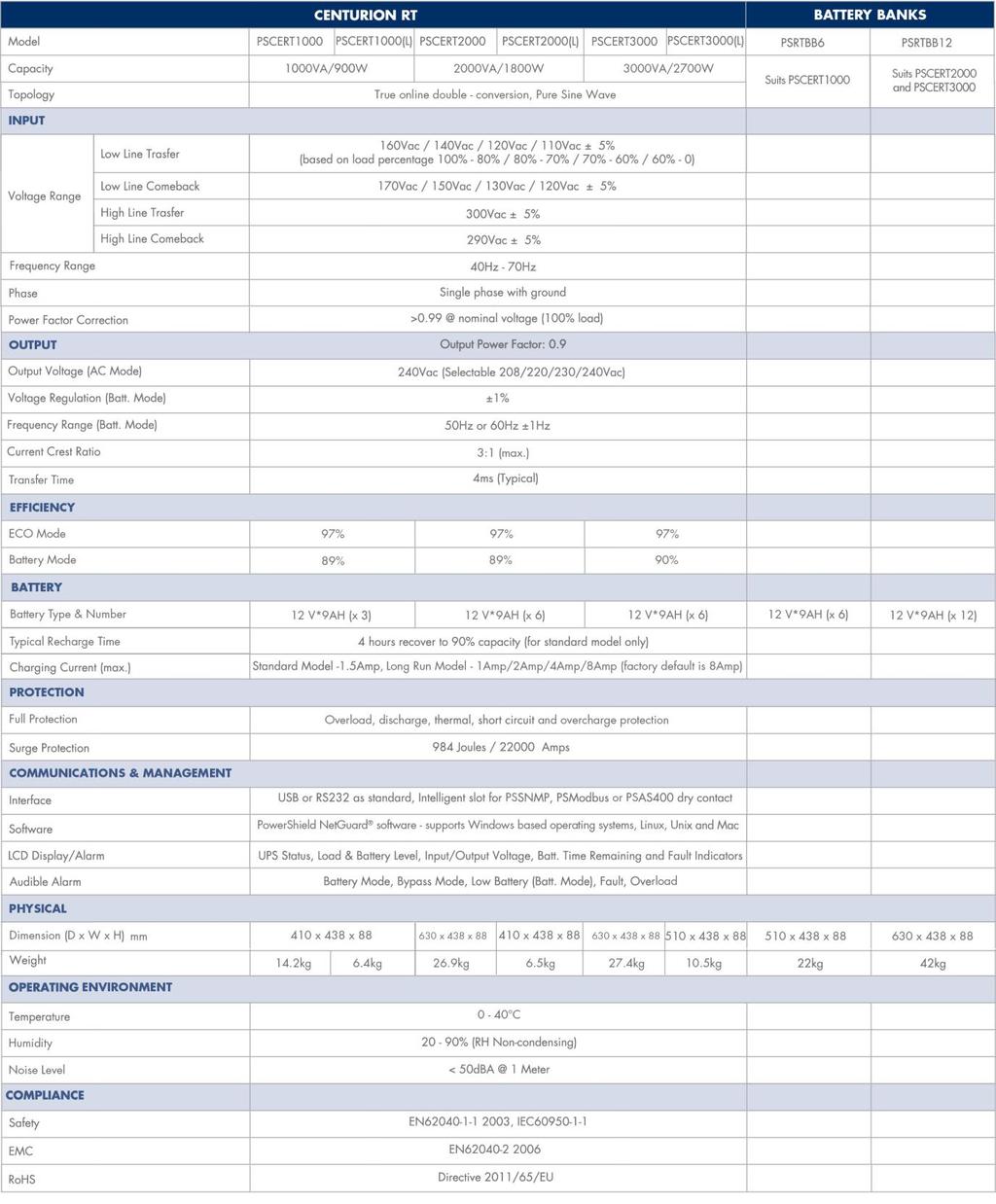
29 6. Specifications 28
30 Power Shield Pty Ltd Warranty Terms & Conditions (PSW ) SERVICE / WARRANTY (Australia) (Tel) Warranty Conditions 1. Power Shield product are warranted for certain specified period (see item 15 below) against failure due to faulty materials or workmanship from the invoice date from the Power Shield Store. Power Shields products are covered by a warranty in addition to all rights available to you by statute. 2. If, within the warranty period, the product does not meet the specification above and the product was installed and operated in accordance with Power Shield and Australian standards and procedures, then Power Shield will, correct any defects due to material or workmanship. 3. If the product has been modified, recalibrated, repaired, opened or tampered with in any way by the customer then its warranty will be void. 4. If the product has been damaged during transport then warranty will be void. 5. If product failed due to fire, earthquake, flood, direct lighting strike, terrorism, pollution, exposed under poison gas, and incorrect utility voltage then warranty will be void. 6. Batteries must be operated within the technical specification limits of the manufacturer and must be fully re-charged at least every three months during storage. 7. If Power Shield at its sole discretion determines that the product has failed, under Power Shield warranty conditions then Power Shield will at its option repair or replace the faulty unit 8. Power Shield will, at its sole discretion, replace the faulty product with an equal or equivalent model of a similar age and condition. 9. If the product, has failed due to reasons that Power Shield at its sole discretion, determines to be outside of warranty conditions, or is found to be not faulty then a minimum inspection and handling fee will be charged and also freight will be for the customer s account. 10. Blown fuses are usually as a result of overload and are not considered a warranty condition and a handling and inspection charge will apply as above 11. For hardwired products, larger than 3KVA, the warranty covers onsite repair for metro areas in capital cities only. For equipment installed in remote locations Power Shield may, at its sole discretion, request that the product be returned to a Power Shield service centre at the customer s cost, 12. Power Shield UPS products are not failsafe devices. Although well designed and manufactured, like all electrical, electronic and mechanical devices it has the potential to fail. This should be taken into consideration when designing any critical system 13. Subject to the applicable Law, in no event shall Power Shield Pty Ltd, it s officers, directors, affiliates or employees be liable for any form of indirect, special, consequential or punitive damages, arising out of the use, service or installation, of the products, whether such damages arise in contract or tort, irrespective of fault, negligence or strict liability or whether Power Shield Pty Ltd has been advised in advance of the possibility of such damages. Specifically, Power Shield Pty Ltd is not liable for any costs, such as lost profits or revenue, loss of equipment, loss of use of equipment, loss of software, loss of data, costs of substitution, claims by third parties, or otherwise. 14. Our products come with guarantees that cannot be excluded under the Australian Consumer Law. You are entitled to a replacement or refund for a major failure and compensation for any other reasonably foreseeable loss or damage. You are also entitled to have the products repaired or replaced if the products fail to be of acceptable quality and the failure does not amount to a major failure. 15. Warranty period commences from the date Power Shield invoices the goods ZapGuard Range: 1 year CompuGuard, SafeGuard, Defender, Commander, Centurion: 2 years Platinum Range: 1 year Gamatronic Range: 1 year To claim a warranty our contact details are as follows Call Service on Or Visit /rmaform/ to process an RMA Or Power Shield Pty Ltd (Head Office) U3, 205 Camboon Rd Malaga, WA 6090 Any claim for expenses must be provided to us in writing and should be sent to our office, detailed above. 29
User Manual. Centurion RT Online UPS 1000/2000/3000. Uninterruptible Power Supply System
 User Manual Centurion RT Online UPS 1000/2000/3000 Uninterruptible Power Supply System IMPORTANT Download latest software /downloads NetGuard 0 Introduction Thank you for choosing PowerShield. PowerShield
User Manual V1.1 OptiFlex 1100 / OptiFlex 2000
 User Manual V1.1 OptiFlex 1100 / OptiFlex 2000 Uninterruptible Power Supply System Table of Contents 1. Important Safety Warning 2 1-1. Transportation 2 1-2. Preparation 2 1-3. Installation 2 1-4. Operation
User Manual V1.0 MaxiFlex 3000
 User Manual V1.0 MaxiFlex 3000 Uninterruptible Power Supply System Table of Contents 1. Important Safety Warning 2 1-1. Transportation 2 1-2. Preparation 2 1-3. Installation 2 1-4. Operation 2 1-5. Maintenance,
USER MANUAL DN / DN
 USER MANUAL DN-170040/ DN-170041 Online UPS Uninterruptible Power Supply System Version:1.0 Table of Contents 1. Important Safety Warning... 1 1-1. Transportation... 1 1-2. Preparation... 1 1-3. Installation...
User Manual. PF0.9 1K/2K/3K Online UPS. Uninterruptible Power Supply System. Version: 1.3
 User Manual PF0.9 1K/2K/3K Online UPS Uninterruptible Power Supply System Version: 1.3 Table of Contents 1. Important Safety Warning... 1 1-1. Transportation... 1 1-2. Preparation... 1 1-3. Installation...
Centurion 1000/1500/2000/3000 Tower/Rackmount On Line UPS User s manual
 Centurion 1000/1500/2000/3000 Tower/Rackmount On Line UPS User s manual www.powershield.com.au 0 Introduction Thank you for choosing PowerShield. PowerShield Centurion UPS series are designed to provide
ULTIMA W SERIES. 1K/2K/3K Online UPS USER MANUAL
 ULTIMA W SERIES 1K/2K/3K Online UPS USER MANUAL Maruson Technology Corporation 18557 East Gale Avenue City of Industry, California 91748, U.S.A. Tel: +1-626-912-8388 Fax: +1-626-912-8680 Toll Free: 1-888-MARUSON
Liebert GXT MT+ User Manual VA Installer/User Guide
 Liebert GXT MT+ User Manual - 1000-3000 VA Installer/User Guide Table of Contents 1. Important Safety Warning 1 1-1. Transportation 1 1-2. Preparation 1 1-3. Installation 1 1-4. Operation 1 1-5. Maintenance,
User M anual. Rack/Tower Online UPS 1K/1.5K/2K/3K
 User M anual Rack/Tower Online UPS 1K/1.5K/2K/3K Uninterruptible Power Supply System Version: 1.2 Table of Contents 1. Important Safety Warning... 1 1-1. Transportation... 1 1-2. Preparation... 1 1-3.
1. Important Safety Warning
 Table of Contents 1. Important Safety Warning... 1 1-1. Transportation... 1 1-2. Preparation... 1 1-3. Installation... 1 1-4. Operation... 1 1-5. Maintenance, service and faults... 2 2. Installation and
UNISTAR SB-NET V 50/60Hz 800VA to 3kVA USER MANUAL
 UNISTAR SB-NET 120-230V 50/60Hz 800VA to 3kVA USER MANUAL 003-2594 REV B Staco Energy is highly specialized in the development and production of uninterruptible power systems (UPS). The UPS s of this series
User Manual. NetGuard IMPORTANT. PSD 650/1200/1600 Line Interactive UPS Uninterruptible Power Supply System. UPS Monitoring Software
 User Manual Thank you for purchasing the Defender 650/1200/1600. It is designed to provide safe and reliable power protection to your precious electronics equipment. Before you start using the product,
User Manual. Online Sinewave UPS. PF=1.0-1K/1.5K/2K/3K Online UPS. (Zasilacz awaryjny 1K/1,5K/2K/3K VA) Seria KR Pro obudowa wolnostojąca (Tower)
 Seria KR Pro obudowa wolnostojąca (Tower)") User Manual Online Sinewave UPS PF=1.0-1K/1.5K/2K/3K Online UPS (Zasilacz awaryjny 1K/1,5K/2K/3K VA) Seria KR Pro obudowa wolnostojąca (Tower) PF=1,0 Uninterruptible Power Supply System Version: 1.4 Table
User Manual Online Sinewave UPS PF=1.0-1K/1.5K/2K/3K Online UPS (Zasilacz awaryjny 1K/1,5K/2K/3K VA) Seria KR Pro obudowa wolnostojąca (Tower) PF=1,0 Uninterruptible Power Supply System Version: 1.4 Table
User Manual. PF1.0 1K/1.5K/2K/3K Online UPS. Uninterruptible Power Supply System. Version: 1.4
 User Manual PF1.0 1K/1.5K/2K/3K Online UPS Uninterruptible Power Supply System Version: 1.4 Table of Contents 1. Important Safety Warning... 1 1-1. Transportation... 1 1-2. Preparation... 1 1-3. Installation...
USER S MANUAL CONTENTS. Uninterruptible Power Supply 1. INTRODUCTION SAFTY INSTRUCTION CABLE CONNECTION... 4
 USER S MANUAL ON-LINE 1K/2K/3KVA CONTENTS 1. INTRODUCTION...... 1 2. SAFTY INSTRUCTION.......... 2 3. CABLE CONNECTION.......... 4 4. SYSTEM DESCRIPTION............ 5 5. UPS OPERATION...... 12 6. TROUBLE
User Manual Rittal PMC UPS 6kVA
 User Manual Rittal PMC UPS 6kVA Germany Rittal GmbH & Co. KG Auf dem Stützelberg D-35745 Herborn Tel.: ++49-27 72-5 05-0 Fax: ++49-27 72-5 05-23 19 Internet: www.rittal.de 26 Contents 1. Introduction...
Centurion. 6000/10000 VA Rack Online UPS. Users Manual.
 Centurion 6000/10000 VA Rack Online UPS Users Manual www.powershield.com.au Introduction Thank you for choosing PowerShield. PowerShield Centurion UPS series are designed to provide the highest level of
1. INTRODUCTION SYSTEM DESCRIPTION Front Panel CONNECTION AND OPERATION TROUBLESHOOTING...8
 Contents : 1. INTRODUCTION...1 2. IMPORTANT SAFETY INSTRUCTIONS...2 3. SYSTEM DESCRIPTION...4 3.1 Front Panel...4 4. CONNECTION AND OPERATION...6 5. TROUBLESHOOTING...8 6. MAINTENANCE...9 6.1 Operation...9
UPS9 Series. Online UPS. User & Installation Manual. Models UPS9-1000, UPS9-1500, UPS9-2000, UPS
 UPS9 Series Online UPS Models UPS9-1000, UPS9-1500, UPS9-2000, UPS9-3000 User & Installation Manual 06-28-16 TABLE of CONTENTS IMPORTANT SAFETY INSTRUCTIONS... 3 INTRODUCTION... 4 PRODUCT DESCRIPTION...
On Line UPS. LUC 1000E / LUC 2000E / LUC 3000E User Manual
 On Line UPS LUC 1000E / LUC 2000E / LUC 3000E User Manual Save This Manual Please read this manual carefully prior to storage, installation, wiring, operation and maintenance of the UPS. This manual contains
T91 Unity Online UPS. 700VA, 1000VA, 1500VA, 2000VA, 3000VA Models. User & Installation Manual
 T91 Unity Online UPS 700VA, 1000VA, 1500VA, 2000VA, 3000VA Models User & Installation Manual www.xpcc.com 2017. All rights reserved. (Rev 3/14/17) Table of Contents Important Safety Warning...3 Transportation...6
USER S MANUAL CONTENTS. Uninterruptible Power Supply 1. INTRODUCTION SAFTY INSTRUCTION SYSTEM DESCRIPTION... 4
 USER S MANUAL PowerWalker VFI 1000 / 3000VA CONTENTS 1. INTRODUCTION...... 1 2. SAFTY INSTRUCTION......... 2 3. SYSTEM DESCRIPTION......... 4 4. CABLE CONNECTION......... 7 5. OPERATION...... 8 6. TROUBLE
NEWTECH PRO X KVA DSP LCD 1/1 ONLINE UNINTERRUPTIBLE POWER SUPPLY USER MANUAL
 NEWTECH PRO X9 6-10 KVA DSP LCD 1/1 ONLINE UNINTERRUPTIBLE POWER SUPPLY USER MANUAL Uninterruptible Power Supply System Please comply with all warnings and operating instructions in this manual strictly.
User Manual. PF0.9 6K/10K Online UPS
 User Manual PF0.9 6K/10K Online UPS Uninterruptible Power Supply System Version: 1.02 Please comply with all warnings and operating instructions in this manual strictly. Save this manual properly and read
User Manual. EGL - 6K/10K Online UPS. Uninterruptible Power Supply System
 User Manual EGL - 6K/10K Online UPS Uninterruptible Power Supply System Please comply with all warnings and operating instructions in this manual strictly. Save this manual properly and read carefully
BRAVER UPS. (Uninterruptible Power System) User s Manual
 User s Manual") BRAVER UPS (Uninterruptible Power System) User s Manual Safety CAUTION! This UPS utilizes voltages that may be hazardous. Do not attempt to disassemble the unit. The unit contains no user replaceable parts.
BRAVER UPS (Uninterruptible Power System) User s Manual Safety CAUTION! This UPS utilizes voltages that may be hazardous. Do not attempt to disassemble the unit. The unit contains no user replaceable parts.
USER MANUAL. E4 LCD TX 5000(S) / 6000(S) / (S) With Output Isolation Transformer. Uninterruptible Power Supply System
 / 6000(S) / (S) With Output Isolation Transformer. Uninterruptible Power Supply System") USER MANUAL E4 LCD TX 5000(S) / 6000(S) / 10 000(S) With Output Isolation Transformer Uninterruptible Power Supply System Table of Contents 1. IMPORTANT SAFETY INSTRUCTIONS:... 2 1-1. TRANSPORTATION...
USER MANUAL E4 LCD TX 5000(S) / 6000(S) / 10 000(S) With Output Isolation Transformer Uninterruptible Power Supply System Table of Contents 1. IMPORTANT SAFETY INSTRUCTIONS:... 2 1-1. TRANSPORTATION...
User Manual. 1P-1P 6KL/7.5KL/10KL Online UPS
 User Manual 1P-1P 6KL/7.5KL/10KL Online UPS Uninterruptible Power Supply System Version: 2.0 Please comply with all warnings and operating instructions in this manual strictly. Save this manual properly
User Manual. 6K/10K Online UPS with Isolation Transformer. Uninterruptible Power Supply System
 User Manual 6K/10K Online UPS with Isolation Transformer Uninterruptible Power Supply System Please comply with all warnings and operating instructions in this manual strictly. Save this manual properly
USER MANUAL ONLINE UPS
 USER MANUAL ONLINE UPS 1-3K/220Vac LCD Uninterruptible Power Systems Please comply with all warnings and operating instructions in this manual and on the unit strictly. Save this manual properly. Do not
Online Battery Backup
 Online Battery Backup UPS-1000-OL - 1000 VA UPS UPS-2000-OL - 2000 VA UPS UPS-3000-OL - 3000 VA UPS User Manual 2016 AMETEK Electronic Systems Protection / Technical Support: 1-800-645-9721 / espsurgex.com
TX90 Isolated Online UPS
 TX90 Isolated Online UPS 1000VA, 2000VA, 3000VA, 5000VA Models User & Installation Manual www.xpcc.com 2016. All rights reserved. (Rev 2/29/16) Table of Contents Important Safety Warning...4 Transportation...4
User Manual. 6K/10K Online UPS. Uninterruptible Power Supply System
 User Manual 6K/10K Online UPS Uninterruptible Power Supply System Please comply with all warnings and operating instructions in this manual strictly. Save this manual properly and read carefully the following
USER MANUAL. PowerMust 1080 LCD (1KVA), Online, IEC PowerMust 2016 LCD (2KVA), Online, IEC PowerMust 3024 LCD (3KVA), Online, IEC
, Online, IEC PowerMust 2016 LCD (2KVA), Online, IEC PowerMust 3024 LCD (3KVA), Online, IEC") USER MANUAL PowerMust 1080 LCD (1KVA), Online, IEC PowerMust 2016 LCD (2KVA), Online, IEC PowerMust 3024 LCD (3KVA), Online, IEC CONTENT 1. Safety and EMC Instructions... 1 1.1 Installation... 1 1.2 Operation...
USER MANUAL PowerMust 1080 LCD (1KVA), Online, IEC PowerMust 2016 LCD (2KVA), Online, IEC PowerMust 3024 LCD (3KVA), Online, IEC CONTENT 1. Safety and EMC Instructions... 1 1.1 Installation... 1 1.2 Operation...
Centurion /20000 VA Rack Online UPS. Users Manual.
 Centurion 10000/20000 VA Rack Online UPS Users Manual www.powershield.com.au Introduction Thank you for choosing PowerShield. PowerShield Centurion UPS series are designed to provide the highest level
P80g Pure Sine Wave Line Interactive UPS
 P80g Pure Sine Wave Line Interactive UPS 3000VA, 5000VA Models User & Installation Manual www.xpcc.com 2016. All rights reserved. (Rev 6/30/16) Table of Contents Important Safety Warning...4 Transportation...4
P80 Pure Sine Wave Line Interactive UPS
 P80 Pure Sine Wave Line Interactive UPS 800VA, 1100VA, 1500VA, 2200VA, 3000VA Models User & Installation Manual www.xpcc.com 2016. All rights reserved. (Rev 6/29/16) Table of Contents Important Safety
CONTENTS 1. INTRODUCTION SAFTY INSTRUCTION CABLE CONNECTION SYSTEM DESCRIPTION INVERTER OPERATION...
 CONTENTS 1. INTRODUCTION...... 1 2. SAFTY INSTRUCTION.......... 2 3. CABLE CONNECTION.......... 4 4. SYSTEM DESCRIPTION............ 5 5. INVERTER OPERATION... 11 6. TROUBLE SHOOTING GUIDE....... 16 7.
Users Manual. Defender 1 8.0KW to 14.0KW Online Emergency Lighting Inverter. Technical Manual # Revision B
 Users Manual Defender 1 8.0KW to 14.0KW Online Lighting Inverter Technical Manual #018-0102-01 Revision B Phone: 1.877.DSPM.POWER 1.877.377.6769 Fax: 909.930.3335 Website: www.dspmanufacturing.com E-Mail:
User Manual. 3/1 10K/20K Online UPS with Isolation Transformer. Uninterruptible Power Supply System
 User Manual 3/1 10K/20K Online UPS with Isolation Transformer Uninterruptible Power Supply System Please comply with all warnings and operating instructions in this manual strictly. Save this manual properly
User Manual Solar Charge Controller 3KW
 User Manual Solar Charge Controller 3KW Version: 1.3 CONTENTS 1 ABOUT THIS MANUAL... 1 1.1 Purpose... 1 1.2 Scope... 1 1.3 SAFETY INSTRUCTIONS... 1 2 INTRODUCTION... 2 2.1 Features... 2 2.2 Product Overview...
USER MANUAL. Blazer Vista 1000/1400/2000. Uninterruptible Power System
 USER MANUAL Blazer Vista 1000/1400/2000 Uninterruptible Power System IMPORTANT SAFETY INSTRUCTIONS SAVE THESE INSTRUCTIONS This manual contains important instructions for model Blazer Vista 1000/1400/2000
UPS2000-G-(1 kva-3 kva) Quick Guide. Issue: 05 Date: HUAWEI TECHNOLOGIES CO., LTD.
 Quick Guide. Issue: 05 Date: HUAWEI TECHNOLOGIES CO., LTD.") UPS2000-G-(1 kva-3 kva) Quick Guide 0 Issue: 05 Date: 2017-07-21 HUAWEI TECHNOLOGIES CO., LTD. 1 Introduction UPS Model Represented By Weight Dimensions (H x W x D) UPS2000-G-1KRTS UPS2000-G-1KRTL UPS2000-G-2KRTS
UPS2000-G-(1 kva-3 kva) Quick Guide 0 Issue: 05 Date: 2017-07-21 HUAWEI TECHNOLOGIES CO., LTD. 1 Introduction UPS Model Represented By Weight Dimensions (H x W x D) UPS2000-G-1KRTS UPS2000-G-1KRTL UPS2000-G-2KRTS
User Manual. Solar Charge Controller 3KW
 User Manual Solar Charge Controller 3KW 1 CONTENTS 1 ABOUT THIS MANUAL... 3 1.1 Purpose... 3 1.2 Scope... 3 1.3 SAFETY INSTRUCTIONS... 3 2 INTRODUCTION... 4 2.1 Features... 4 2.2 Product Overview... 5
Installation Guide Smart-UPS On-Line SRT1000/SRT1500 XLA Tower/Rack-Mount
 Installation Guide Smart-UPS On-Line SRT1000/SRT1500 XLA Tower/Rack-Mount Important Safety Messages Read the instructions carefully to become familiar with the equipment before attempting to install, operate,
Installation Power Management Unit Battery Cables and Battery Harness
 Installation Power Management Unit Battery Cables and Battery Harness Important Safety Messages SAVE THESE INSTRUCTIONS - This manual contains important instructions that should be followed during installation
Users Manual. Cobra Plus Stand-By Emergency Lighting Inverter. Technical Manual # Revision B
 Users Manual Cobra Plus Stand-By Lighting Inverter Technical Manual #018-0110-01 Revision B Phone: 1.877.DSPM.POWER 1.877.377.6769 Fax: 909.930.3335 Website: www.dspmanufacturing.com E-Mail: techsupport@dspmanufacturing.com
User Manual. PF 1 6K/10K Rack/Tower Online UPS
 User Manual PF 1 6K/10K Rack/Tower Online UPS Uninterruptible Power Supply System Version: 1.0 Please comply with all warnings and operating instructions in this manual strictly. Save this manual properly
User Manual. 3/1 10K~30K Online UPS
 User Manual 3/1 10K~30K Online UPS Uninterruptible Power Supply System Version: 1.7 Please comply with all warnings and operating instructions in this manual strictly. Save this manual properly and read
On-line, Single Phase, Double Conversion UPS
 V Series Standard Universal Tower/Rack Mount 1, 2, 3 kva On-line, Single Phase, Double Conversion UPS The UniStar V features a field-proven Digital Signal Processor (DSP) achieving high reliability, while
FRUK+19 6K / FRUK+19 10K FRUK RM-01V / FRUK RM-01V
 User Manual FRUK+19 6K / FRUK+19 10K FRUK+19-6000RM-01V / FRUK+19-10000RM-01V Online UPS Uninterruptible Power Supply System Please comply with all warnings and operating instructions in this manual strictly.
P90L Online UPS. P90L-1500, 2000, 3000 Models. User & Installation Manual
 P90L Online UPS P90L-1500, 2000, 3000 Models User & Installation Manual www.xpcc.com 2014. All rights reserved. (Rev 8/13/14) Table of Contents Introduction...6 Product Description...6 Double Conversion
User Manual. 6K/10K Online UPS with Isolation Transformer
 User Manual 6K/10K Online UPS with Isolation Transformer Uninterruptible Power Supply System Version: 1.2 Please comply with all warnings and operating instructions in this manual strictly. Save this manual
User Manual. Digital Energy Uninterruptible Power Supply ML Series UPS VA. GE Digital Energy Power Quality. GE imagination at work
 GE Digital Energy Power Quality User Manual Digital Energy Uninterruptible Power Supply ML Series UPS 350-500-700-1000 VA GE Consumer & Industrial SA General Electric Company CH 6595 Riazzino (Locarno)
UPS USER MANUAL F-11 LINE INTERACTIVE UPS GENERAL PURPOSE UPS 650VA/1200VA/2200VA
 UPS USER MANUAL F-11 LINE INTERACTIVE UPS GENERAL PURPOSE UPS 650VA/1200VA/2200VA IMPORTANT SAFETY INSTRUCTIONS SAVE THESE INSTRUCTIONS This manual contains important instructions for models Aurora Vista
Thank you for choosing EATON products. Safety information and operating instructions are included in this manual. Do not attempt to operate the UPS
 Thank you for choosing EATON products. Safety information and operating instructions are included in this manual. Do not attempt to operate the UPS until reading through this manual carefully. Observe
User Manual 4KVA/ 5KVA INVERTER / CHARGER. With MPPT Controller
 User Manual 4KVA/ 5KVA INVERTER / CHARGER With MPPT Controller CONTENTS ABOUT THIS MANUAL... 1 Purpose... 1 Scope... 1 SAFETY INSTRUCTIONS... 1 INTRODUCTION... 2 Features... 2 Basic System Architecture...
User Manual Digital Energy Uninterruptible Power Supply ML Series UPS VA GE Digital Energy Power Quality
 GE Digital Energy Power Quality User Manual Digital Energy Uninterruptible Power Supply ML Series UPS 350-500-700-1000 VA GE imagination at work GB User Manual Digital Energy Uninterruptible Power Supply
User Manual 1KVA/ 2KVA/ 3KVA INVERTER / CHARGER
 User Manual 1KVA/ 2KVA/ 3KVA INVERTER / CHARGER CONTENTS ABOUT THIS MANUAL... 1 Purpose... 1 Scope... 1 SAFETY INSTRUCTIONS... 1 INTRODUCTION... 2 Features... 2 Basic System Architecture... 2 Product Overview...
Operation Manual. Smart-UPS C. Uninterruptible Power Supply 1000/1500/2000/3000 VA. 120/230 Vac. Tower. su0813a
 Operation Manual Smart-UPS C Uninterruptible Power Supply 1000/1500/2000/3000 VA 120/230 Vac Tower su0813a Important Safety Messages SAVE THESE INSTUCTIONS - This manuals contains important instructions
Standard 1000VA, 2000VA & 3000VA Universal Tower/Rack Mount LB Extended Models 900VA, 1700VA & 2500VA
 V Series 120/120VAC Standard 1000VA, 2000VA & 3000VA Universal Tower/Rack Mount LB Extended Models 900VA, 1700VA & 2500VA On-line, Single Phase, Double Conversion UPS The UniStar V features a field-proven
Installation and user manual. 5SC 500i 5SC 750i 5SC 1000i 5SC 1500i ENGLISH. Copyright 2013 EATON All rights reserved.
 ENGLISH Installation and user manual 5SC 500i 5SC 750i 5SC 1000i 5SC 1500i Copyright 2013 EATON All rights reserved. Service and support: Call your local service representative Certification Standards
Series 120/120VAC Universal Tower/Rack Mount
 V Series 120/120VAC Universal Tower/Rack Mount Standard 1000VA, 1500VA, 2000VA & 3000VA LB Extended Models 900VA, 1250VA, 1700VA & 2500VA On-line, Single Phase, Double Conversion UPS The UniStar V features
1. INTRODUCTION. Features:
 1. INTRODUCTION This series is a compact and fully pure sinewave line interactive UPS, and it designs for critical application and environment, such as desktops, servers, workstations, and other networking
User Manual 1KVA-5KVA INVERTER / CHARGER
 User Manual 1KVA-5KVA INVERTER / CHARGER Version: 1.7 Table Of Contents ABOUT THIS MANUAL... 1 Purpose... 1 Scope... 1 SAFETY INSTRUCTIONS... 1 INTRODUCTION... 2 Features... 2 Basic System Architecture...
CONTENTS 1. INTRODUCTION SAFTY INSTRUCTION CABLE CONNECTION SYSTEM DESCRIPTION OPERATION... 9
 USER MANUAL 1 CONTENTS 1. INTRODUCTION... 1 2. SAFTY INSTRUCTION... 3 3. CABLE CONNECTION... 4 4. SYSTEM DESCRIPTION... 5 5. OPERATION... 9 6. TROUBLE SHOOTING GUIDE... 25 7. OPERATION MODES..... 27 8.
Installation and user manual 5SC 500 5SC 750 5SC SC SC 500G 5SC 750G 5SC 1500G ENGLISH. Copyright 2013 EATON All rights reserved.
 ENGLISH Installation and user manual SC 00 SC 70 SC 000 SC 00 SC 00G SC 70G SC 00G Copyright 03 EATON All rights reserved. Service and support: Call your local service representative Page IMPORTANT SAFETY
User Manual 1.5KVA-3KVA INVERTER / CHARGER. Version: 1.1
 User Manual 1.5KVA-3KVA INVERTER / CHARGER Version: 1.1 Table Of Contents ABOUT THIS MANUAL... 1 Purpose... 1 Scope... 1 SAFETY INSTRUCTIONS... 1 INTRODUCTION... 2 Features... 2 Basic System Architecture...
TOWER MAXI T SINGLE CONVERSION ON LINE UPS SYSTEMS
 INSTRUCTION MANUAL TOWER MAXI T SINGLE CONVERSION ON LINE UPS SYSTEMS September 2000 TOWER UPS DISTRIBUTION (PTY) LTD 1 1. INTRODUCTION T A B L E O F C O N T E N T S 1.1 General Description... 3 1.2 Features...
Foreword
 Foreword Content 1. Summary 2. Safety instruction Safety Symbol Indication Attention Static discharge sensitive Electric shock Dangerous Indicate risk of serious injury or death or seriously damage the
User manual. Solar Hybrid 1-5KVA. Uninterruptible Power Supply / Charger
 User manual Solar Hybrid 1-5KVA Uninterruptible Power Supply / Charger All rights reserved. The information in this document is subject to change without notice. Thank you for purchasing this series UPS.
User Manual SOLARMAX 1KVA/ 2KVA/ 3KVA INVERTER / CHARGER
 User Manual SOLARMAX 1KVA/ 2KVA/ 3KVA INVERTER / CHARGER WWW.POWERHIGHWAY.NET CONTENTS ABOUT THIS MANUAL... 1 Purpose... 1 Scope... 1 SAFETY INSTRUCTIONS...... 1 INTRODUCTION... 2 Features... 2 Basic System
Installation and Operation Back-UPS BX550CI-CN
 Installation and Operation Back-UPS BX550CI-CN Safety and General Information This unit is intended for indoor use only. Do not operate this unit in direct sunlight, in contact with fluids, or where there
User Manual Easy UPS On-Line SRV Series 1000VA, 2000VA, 3000VA
 User Manual Easy UPS On-Line SRV Series 1000VA, 2000VA, 3000VA Important Safety Information Read the instructions carefully and look at the equipment to become familiar with the device before trying to
Power Inverter. User s Manual. Diamond Series CPD1200EILCD
 Power Inverter Diamond Series CPD1200EILCD User s Manual 2 TABLE OF CONTENTS 1 IMPORTANT SAFETY INSTRUCTIONS..4 2 INSTALLATION....5 2-1 Unpacking...5 2-2 Product Overview & Outlook..5 2-3 Power Requirements
USER MANUAL. PowerMust 1400/2000 LCD. Uninterruptible Power System
 USER MANUAL PowerMust 1400/2000 LCD Uninterruptible Power System IMPORTANT SAFETY INSTRUCTIONS SAVE THESE INSTRUCTIONS This manual contains important instructions for model Power Must 1400/2000 LCD that
USER MANUAL 3/3 10K~20K Online UPS
 USER MANUAL EN 3/3 10K~20K Online UPS Uninterruptible Power Supply System Please comply with all warnings and operating instructions in this manual strictly. Save this manual properly and read carefully
12/24 VOLT AUTOMATIC SOLAR CHARGE CONTROLLER
 12/24 VOLT AUTOMATIC SOLAR CHARGE CONTROLLER P/No.s SC320 & SC330 WARNING Please read these instructions completely prior to installation. Lead acid batteries can be dangerous. Ensure no sparks or flames
Broadband PowerShield. CP27U Models. User Manual
 Broadband PowerShield CP27U Models User Manual 990-2366C 04/2016 Chapter 1: General Information The PowerShield provides a power source for broadband telephony, Fiber-to-the-Home/Premise (FTTH/P), and
RT Series Step Down Transformer for RT Series UPS 6-10kVA UL Input Vac Output Vac User Guide
 RT Series Step Down Transformer for RT Series UPS 6-10kVA UL Input 208-240 Vac Output 208-120 Vac User Guide UNLESS SPECIFICALLY AGREED TO IN WRITING, SELLER (A) MAKES NO WARRANTY AS TO THE ACCURACY, SUFFICIENCY
MICROCARE 3 PHASE INVERTER MANUAL
 3 PHASE INVERTER MANUAL 1 Contents 1. INTRODUCTI... 3 2. SAFETY INSTRUCTI... 4 3. SYSTEM DESCRIPTI... 6 4. WIRING DIAGRAM... 9 5. INVERTER OPERATI... 10 6. INVERTER CLUSTER PROGRAMMING... 13 7. CLUSTER
User Manual 1.5KVA-3KVA INVERTER / CHARGER
 User Manual 1.5KVA-3KVA INVERTER / CHARGER Version: 1.0 Table Of Contents ABOUT THIS MANUAL... 1 Purpose... 1 Scope... 1 SAFETY INSTRUCTIONS... 1 INTRODUCTION... 2 Features... 2 Basic System Architecture...
POWERVAR Sinergy III Rackmount / Tower User Instruction Manual. Sinergy III 120 Volt UPS. Sinergy III Volt UPS
 POWERVAR Sinergy III Rackmount / Tower User Instruction Manual Sinergy III 120 Volt UPS ACDEF700-11 700 VA UPS ACDEF1000-11 1000 VA UPS E024-12 External Battery Cabinet ACDEF1500-11 1500 VA UPS E036-12
User Manual 5KVA/5KW INVERTER / CHARGER. Version: 1.3
 User Manual 5KVA/5KW INVERTER / CHARGER Version: 1.3 Table Of Contents ABOUT THIS MANUAL... 1 Purpose... 1 Scope... 1 SAFETY INSTRUCTIONS... 1 INTRODUCTION... 2 Features... 2 Basic System Architecture...
Installation and Operation
 Installation and Operation Smart-UPS External Battery Pack Tower/Rack-Mount 2U/3U SRC192XLBP SRC240XLBP1 SRC240XLBP2 oem0141a Smart-UPS External Battery Pack Tower/Rack-Mount 2U/3U SRC192XLBP SRC240XLBP1
Start UP Guide. Symmetra LX Tower Rack-Mount. UPS Models 200 V, 4-8 kva 208/240 V, 4-8 kva 220/230/240 V, 4-8 kva
 Start UP Guide Symmetra LX Tower Rack-Mount UPS Models 200 V, 4-8 kva 208/240 V, 4-8 kva 220/230/240 V, 4-8 kva 200 V, 4-16 kva 208/240 V, 4-16 kva 220/230/240 V, 4-16 kva Important Safety Messages SAVE
Installation and Operation Manual Back-UPS BX1100CI-CN
 Installation and Operation Manual Back-UPS BX1100CI-CN Safety and General Information This unit is intended for indoor use only. Do not operate this unit in direct sunlight, in contact with fluids, or
Installation Guide Smart-UPS On-Line SRT1000/1500 UXI-NCLI, SRT1000/1500 UXI-LI, Tower/Rack-Mount
 Installation Guide Smart-UPS On-Line SRT1000/1500 UXI-NCLI, SRT1000/1500 UXI-LI, Tower/Rack-Mount Important Safety Messages Read the instructions carefully to become familiar with the equipment before
XPC-EBP64 External Battery Pack User & Installation Manual Xtreme Power Conversion Corporation. All rights reserved.
 XPC-EBP64 User & Installation Manual www.xpcc.com 2015. All rights reserved. (Rev 9/28/15) Table of Contents Introduction...5 Product Description...5 Extended Battery Pack Configurations...6 Safety Information...7
User Manual Easy UPS On-Line SRVS Series Rack-Mount 1000VA, 2000VA, 3000VA
 User Manual Easy UPS On-Line SRVS Series Rack-Mount 1000VA, 2000VA, 3000VA Important Safety Information Read the instructions carefully and look at the equipment to become familiar with the device before
Solar Hybrid Inverter SP Brilliant Series
 User Manual Solar Hybrid Inverter SP Brilliant Series Version: 1.5 Table Of Contents ABOUT THIS MANUAL... 1 Purpose... 1 Scope... 1 SAFETY INSTRUCTIONS... 1 INTRODUCTION... 2 Features... 2 Basic System
Pulsar EXtreme CLA 1500C
 www.mgeups.com MGE UPS SYSTEMS Pulsar EXtreme CLA 500C Installation and user manual 503998EN/AA - Page Introduction Thank you for selecting an MGE UPS SYSTEMS product to protect your electrical equipment.
USER MANUAL. Power GUARD UPS. Uninterruptible Power System
 USER MANUAL Power GUARD UPS Uninterruptible Power System IMPORTANT SAFETY INSTRUCTIONS SAVE THESE INSTRUCTIONS This manual contains important instructions for Power GUARD that should be followed during
WARNINGS, CAUTIONS AND NOTES
 Welcome Please read this manual thoroughly before installing and operating your new Power Bright Power Inverter. This manual contains information you need to obtain the performance required for your application.
1KVA/ 2KVA/ 3KVA/ 4KVA/ 5KVA MS, LV MPPT INVERTER / CHARGER. User Manual. Version: 2.3
 1KVA/ 2KVA/ 3KVA/ 4KVA/ 5KVA MS, LV MPPT INVERTER / CHARGER User Manual Version: 2.3 Table Of Contents ABOUT THIS MANUAL... 1 Purpose... 1 Scope... 1 SAFETY INSTRUCTIONS... 1 INTRODUCTION... 2 Features...
User Manual 1KVA-5KVA (PF1) INVERTER / CHARGER. Version: 1.0
 INVERTER / CHARGER. Version: 1.0") User Manual 1KVA-5KVA (PF1) INVERTER / CHARGER Version: 1.0 Table Of Contents ABOUT THIS MANUAL... 1 Purpose... 1 Scope... 1 SAFETY INSTRUCTIONS... 1 INTRODUCTION... 2 Features... 2 Basic System Architecture...
User Manual 1KVA-5KVA (PF1) INVERTER / CHARGER Version: 1.0 Table Of Contents ABOUT THIS MANUAL... 1 Purpose... 1 Scope... 1 SAFETY INSTRUCTIONS... 1 INTRODUCTION... 2 Features... 2 Basic System Architecture...
Solar Hybrid Inverter SP Efecto Series
 User Manual Solar Hybrid Inverter SP Efecto Series Version 1.2 Table Of Contents ABOUT THIS MANUAL... 1 Purpose... 1 Scope... 1 SAFETY INSTRUCTIONS... 1 INTRODUCTION... 2 Features... 2 Basic System Architecture...
MPPT Controller PVTS Series User Manual. User Manual. 800W-4000W Hybrid solar inverter. Version: 1.4
 User Manual 800W-4000W Hybrid solar inverter Version: 1.4 Table Of Contents ABOUT THIS MANUAL... 1 Purpose... 1 Scope... 1 SAFETY INSTRUCTIONS... 1 INTRODUCTION... 2 Features... 2 Basic System Architecture...
User Manual 1KVA-5KVA INVERTER / CHARGER
 User Manual 1KVA-5KVA INVERTER / CHARGER Table Of Contents ABOUT THIS MANUAL... 1 Purpose... 1 Scope... 1 SAFETY INSTRUCTIONS... 1 INTRODUCTION... 2 Features... 2 Basic System Architecture... 2 Product
User Manual Back-UPS BX650CI-MS 230 Vac with AVR
 User Manual Back-UPS BX650CI-MS 230 Vac with AVR Overview Safety and General Information Inspect the package contents upon receipt. Notify the carrier and dealer if there is any damage. Read the Safety