Product Selection Guide: T3 Series- 100 & 225 Amps
|
|
|
- Preston Webster
- 6 years ago
- Views:
Transcription


1 Selection Guide: T3 Series- 100 & 225 Amps
2 T3 Series INTRODUCTION & SPECS Specs This specification covers the electrical characteristics and general requirements for a track busway system, hereafter referred to as (Track Busway). The system shall be designed primarily for overhead distribution of electrical power; supporting designated work areas and equipment. Once installed the Busway will provide a simple, versatile, fast and economic means of distributing power. Loads fed from a variety of plug-in units can be easily added or removed without shutting power down to the busway. The Track Busway shall be designed and manufactured to the following standards: 1. Underwriters Laboratories Standard, UL 857 The common UL, CSA, and ANCE Standard for Busways that is derived from the fifth edition of CSA Standard C22.2 No. 27, the twelfth edition of UL 857, and the second edition of NMX-J ANCE. 2. Low Voltage Switchgear and Controlgear Assemblies, Part 1: Type Tested and partially type tested Assemblies, IEC & IEC Introduction Universal Electric Corporation (UEC) is the leader in electrical power distribution in the mission critical, commercial and light industrial industries with STARLINE Track Busway. This system was designed to meet the rugged specification of the UL857, Busway and Associated Fittings, with the flexible features of track lighting - and is available in systems with 100 or 225 amps with isolated ground. Track Busway is the simple, versatile, fast and economical solution for supplying power to electrical loads and is unique because the busway can be instantly tapped at any location, with a variety of plug-in units. The Selection Guide was developed to help the design engineer understand and consider all of the options available with STARLINE Track Busway when designing a system. This guide is all-inclusive; however, UEC excels at collaborating with design engineers to provide solutions for any application. If you have a need that is not found in this guide, please contact us at or us at info@uecorp.com. We will be happy to answer your questions over the telephone or schedule a visit with one of our local representatives. Also, if viewing this guide in print, please keep in mind that this is a working document. UEC reseves the right to change information and descriptions of listed services and products. The latest version of this guide is available for download at downloads.uecorp.com/starline/busway/. *All standards and certifications available upon request 3.1 StarlinePower.com
3 T3 Series TABLE OF CONTENTS SYSTEM LAYOUT DRAWING GROUND OPTIONS POLARITY TIPS SYSTEM LAYOUT TIPS COMPONENT RELATIONSHIP TIPS T3 Systems STRAIGHT SECTIONS STRAIGHT SECTIONS: PRODUCT NUMBERS ELBOW SECTIONS ELBOW SECTIONS: PRODUCT NUMBERS TEE SECTIONS TEE SECTIONS: PRODUCT NUMBERS END FEED UNITS END FEED UNITS: METERING END FEED UNITS: PRODUCT NUMBERS ABOVE FEED UNITS ABOVE FEED UNITS: PRODUCT NUMBERS T3 Systems STRAIGHT SECTIONS STRAIGHT SECTIONS: PRODUCT NUMBERS ELBOW SECTIONS ELBOW SECTIONS: PRODUCT NUMBERS TEE SECTIONS TEE SECTIONS: PRODUCT NUMBERS END FEED UNITS END FEED UNITS: METERING END FEED UNITS: PRODUCT NUMBERS ABOVE FEED UNITS ABOVE FEED UNITS: PRODUCT NUMBERS RAL Colors ACCESSORIES: SUPPORT HARDWARE ACCESSORIES: SUPPORT HARDWARE ACCESSORIES: SUPPORT HARDWARE ACCESSORIES: CONNECTION HARDWARE ACCESSORIES: INSTALLATION TOOL SERVICES StarlinePower.com
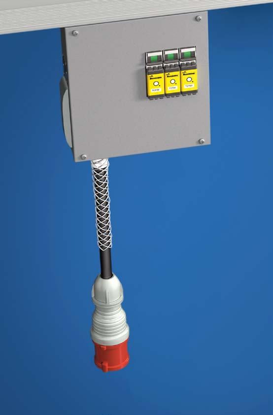
4 T3 Series SYSTEM LAYOUT DRAWING End Cap Support Hardware Housing Section Tee Elbow Installation Tool End Feed Unit Plug-In Unit example: For further information on plug-in unit options, please visit the Plug- In Units section 3.3 StarlinePower.com

 vs.")
5 T3 Series GROUND OPTIONS Case Ground/Chassis Earth Uses aluminum housing and no extra copper bar. Dedicated Ground/Earth Extra bar in busway for ground. Everything tied together inside plugs. Bar and housing at same potential. Isolated Ground/Earth Orange receptacles in plugs. Case ground isolated from copper ground bar. Isolated ground carried back to panel by others. *U.S.: For further details about Dedicated Ground vs. Isolated Ground, please reference our Isolated Ground vs. Dedicated Ground tech brief on *International: For further details about Dedicated Earth vs. Isolated Earth, please reference our Metric: Isolated Earth (IG) vs. Dedicated Earth (DG) tech brief on StarlinePower.com
6 T3 Series POLARITY TIPS STARLINE utilizes a unique polarizing method to prevent mismatched components from being inadvertently connected to each other. The system is designed to prevent cross phasing during installation. It is particularly important to understand this design concept prior to ordering and/or installing some components. For example, if the face direction of a STARLINE plug-in unit is important in your installation consider that they will always face the conductor side. Certain plug-in units are reversible, designated by R, to face devices away from the conductor side. All standard outlet boxes face the conductor side unless reversed plugs are specified Polarizing Strip = Plug-In Unit Front-Facing Direction = 3.5 StarlinePower.com
7 T3 Series SYSTEM LAYOUT TIPS Power Feeds Determine location of power feeds based on relation to power source, existing feeders and voltage drop concerns for longer runs. Support Hardware Support hardware is spaced no more than 10 ft. (3m) apart. Refer to page 3.31 for support hardware details. Contact your local Starline applications engineer for any questions. Installation Printed installation drawings are supplied with each system shipment and they are also available for download online at starline/busway/. CAD files of these drawings are also available by contacting your local Starline applications engineer. Busway Housing Sections Standard Busway lengths are available in 5 ft (1.5m) 10 ft (3m) and 20 foot (6m) increments. Although the factory can cut individual STARLINE Track Busway sections to any length under 20 feet (6m), it is highly recommended to keep all layout runs in increments of 5 feet (1.5m) to simplify layout and installation. Custom lengths can be made but can increase lead time and make layout and installation a bit more complex. Busway Tees and Elbows Sections Try to keep all runs as straight as possible as tees and elbows are added cost. Pay close attention to polarity on the elbows. The polarity will need to match the adjacent busway section(s) to be compatible. Length of Busway for a One Volt Drop in Line to Line Voltage: SYSTEM DESIGNATION DISTRIBUTED LOAD VOLTAGE 0.8 PF Single Phase VOLTAGE 0.8 PF Three Phase 100T3 (standard) 100 amps 42 Ft. (12.8m) 72 Ft. (22m) 225T3 (standard) 225 amps 28 Ft. (8.5m) 48 Ft. (14.6m) 3.6 StarlinePower.com
8 T3 Series COMPONENT RELATIONSHIP TIPS When ordering material, it is important to understand the relationship between various components. Examples: Each piece of housing (straights and elbows) requires a joint kit (containing two housing couplers and one bus connector). Determine the total number of housing sections (regardless of length) as this becomes the number of joint kits that will be needed. -Add one extra joint kit for each tee section If this is your first installation for 100T3 or 225T3 systems, you will need to order an Installation Tool (ST3IT). General support hardware rule to follow: 10 ft (3m) maximum spacing between supports and we recommend 10% more than the required quantity to cover potential layout changes. Total Power Feeds and End Caps can be determined by counting the total number of unconnected runs. Before specifying or ordering elbow or tee connectors, it is important to understand polarity and the relationship to direction of outlets. Please refer to pg. 3.5 Polarity Tips for more detail. 3.7 StarlinePower.com
9 100T3 Systems STRAIGHT SECTIONS Description Track Busway straight section consists of an extruded aluminum shell with channel type solid copper busbars contained in a full length insulator mounted on one side of the interior wall. Each straight has an open access slot over its entire length for the insertion of turn-n-lock plug-in units. Housing configuration is 4 pole, 600 Volt for U.S. systems, and 4 pole, 415 Volt for metric systems (IEC). Busway joint connections are made using a joint kit, which includes a housing coupler and bus connector. An installation tool is used to insert the bus connector in between the busbar channels of the two sections for a solid spring-tempered electrical connection. A housing coupler is then used to make a solid mechanical connection. MATERIAL: Extruded Aluminum (60.33mm) (60.33mm) RATINGS: LENGTH: 100% Ground Path U.S: 100 Amp, 600 Volt Metric: 100 Amp, 415 Volt 5 Ft (1.5m), 10 Ft (3m), 20 Ft. (6m); or custom lengths between 2-20 Ft. (1.5-6m) (L3) (L2) (L1) (106.35mm) (L3) (L2) (L1) (106.35mm) VOLTAGE DROP: distributed load Single Phase 1V per 54ft (16.5m) (.8PF) Three Phase 1V per 62ft (19m) (.8PF) WEIGHT: 10 ft. (3m) 4 pole: 26 lbs/11.8 kg 10 ft. (3m) 4 pole w/ ground: 30 lbs/13.6 kg 10 ft. (3m) 4 pole w/ 200% N: 33 lbs/15 kg 10 ft. (3m) 4 pole w/ ground & 200% N: 34 lbs/15.4 kg (N) US L1 or Phase A L2 or Phase B L3 or Phase C Neutral Ground (N) Metric L1 or Phase A L2 or Phase B L3 or Phase C Neutral Ground Bus Connector Installation Tool 3.8 StarlinePower.com
10 100T3 Systems STRAIGHT SECTIONS: PRODUCT NUMBERS U S 100 T3 C 4 S C 1. System 2. Type 3. Frame 4. Compatibility 5. Material - BLK 0 *10. Paint color 6. Neutral/ Ground busbar 7. Polarization *11. Tape Marking 8. Straight Length 9. Busway Access *Optional **RAL (please see page 3.30) 1. System (standard of measure) U U.S. M Metric 2. Type (section component) S Straight section 3. Frame (maximum amperage) amps 4. Compatibility (frame compatibility) T3 T3 systems *10. Paint Color (allows painting of the busway housing) 000 None RED Paint UEC Red BLK Paint UEC Black BLU Paint UEC Blue WHT Paint UEC White **RAL system can also be used; reference page 3.30 *11. Tape Marking (allows colored tape on the polarizing strip side of busway housing) 0 None 3 Tape UEC Black 4 Tape UEC White 6 Tape UEC Red 7 Tape UEC Blue 5. Material (busbar material) C Copper 6. Neutral/Ground Busbar (size of neutral busbar and/or ground) 4 3 Phase plus Neutral G 3 Phase plus Neutral plus N 3 Phase plus 200% Internal Ground Conductor Neutral F 3 Phase plus 200% Neutral plus Internal Ground Conductor 7. Polarization (orientation of section for mating purposes) S Standard 8. Straight Length (length of section) XXYY XX = feet, YY = inches (for U.S.) MXYY X = meters, YY = centimeters (for Metric) 9. Busway Access (how plugs access the busway) C Continuous Examples: US100T3C4S-0206C = US, Straight section, 100 amps, T3, Copper conductor, 3 Phase plus neutral, Standard polarization- 2ft. 6in., Continuous access MS100T3CNS-M600C-P013 = Metric, Straight section, 100 amps, T3, Copper conductor, 3 Phase plus 200% Neutral, Standard polarization- 6m, Continuous access- RAL 1001, black tape 3.9 StarlinePower.com
11 100T3 Systems ELBOW SECTIONS Description Elbows are used for making a 90 degree in a Busway run. Horizontal and vertical elbows are available. Specify external or internal elbow according to the orientation of the busbars in the Busway sections to be connected. Elbow sections are connected to adjacent Busway sections using an installation tool and joint kit that includes a housing coupler and bus connector (ordered separately). This handles both the mechanical and electrical connection between a straight section and elbow section of busway. Joint Kit Joint Kit WEIGHT: 5.6 lbs (2.5 kg) Elbow = Polarizing Strip 12 (305mm) 12 (305mm) 12 (305mm) 12 (305mm) External Elbow Internal Elbow External Elbow Internal Elbow 3.10 StarlinePower.com
12 100T3 Systems ELBOW SECTIONS: PRODUCT NUMBERS U E 100 T3 C 4 S - IN 1. System 2. Type 3. Frame 4. Compatibility - BLK 0 *9. Paint color 5. Material 6. Neutral/ Ground busbar *10. Tape Marking 7. Polarization 8. Turning Direction *Optional **RAL (please see page 3.30) 1. System (standard of measure) U U.S. M Metric 2. Type (section component) E Elbow section 3. Frame (maximum amperage) amps 4. Compatibility (frame compatibility) T3 T3 systems *9. Paint Color (allows painting of the busway housing) 000 None RED Paint UEC Red BLK Paint UEC Black BLU Paint UEC Blue WHT Paint UEC White **RAL system can also be used; reference page 3.30 *10. Tape Marking (allows colored tape on the polarizing strip side of busway housing) 0 None 3 Tape UEC Black 4 Tape UEC White 6 Tape UEC Red 7 Tape UEC Blue 5. Material (busbar material) C Copper 6. Neutral/Ground Busbar (size of neutral busbar and/or ground) 4 3 Phase plus Neutral G 3 Phase plus Neutral plus N 3 Phase plus 200% Internal Ground Conductor Neutral F 3 Phase plus 200% Neutral plus Internal Ground Conductor 7. Polarization (orientation of section for mating purposes) S Standard 8. Turning Direction (direction of section polarizing strip) IN Internal EX External Examples: UE100T3C4S-IN-BLK4 = US, Elbow section, 100 amps, T3, Copper conductor, 3 Phase plus neutral, Standard polarization- Internal- painted black, white tape ME100T3CNS-EX = Metric, Elbow section, 100 amps, T3, Copper conductor, 3 Phase plus 200% Neutral, Standard polarization- External 3.11 StarlinePower.com
13 100T3 Systems TEE SECTIONS Description Tee sections are used for creating a 90 degree branch leg in a Busway run. When laying out a system, specify the correct busbar orientation of the tee. Indicate right or left, external or internal busbars. External tees are preferred. Tee sections are connected to adjacent Busway sections using an installation tool and joint kit that includes a housing coupler and bus connector (ordered separately). This handles both the mechanical and electrical connection between a straight section and tee section of busway. = Polarizing Strip WEIGHT: 8 lbs ( 3.6 kg) (610mm) (305mm) 24 (610mm) 12 (305mm) External-Left (EL) External-Right (ER) 24 (610mm) 12 (305mm) 24 (610mm) 12 (305mm) Internal-Left (IL) Internal-Right (IR) 3.12 StarlinePower.com
14 100T3 Systems TEE SECTIONS: PRODUCT NUMBERS U T 100 T3 C 4 S - IR 1. System 2. Type 3. Frame 4. Compatibility - BLK 0 *9. Paint color 5. Material 6. Neutral/ Ground busbar *10. Tape Marking 7. Polarization 8. Turning Direction *Optional **RAL (please see page 3.30) 1. System (standard of measure) U U.S. M Metric 2. Type (section component) T Tee section 3. Frame (maximum amperage) amps 4. Compatibility (frame compatibility) T3 T3 systems *9. Paint Color (allows painting of the busway housing) 000 None RED Paint UEC Red BLK Paint UEC Black BLU Paint UEC Blue WHT Paint UEC White **RAL system can also be used; reference page 3.30 *10. Tape Marking (allows colored tape on the polarizing strip side of busway housing) 0 None 3 Tape UEC Black 4 Tape UEC White 6 Tape UEC Red 7 Tape UEC Blue 5. Material (busbar material) C Copper 6. Neutral/Ground Busbar (size of neutral busbar and/or ground) 4 3 Phase plus Neutral G 3 Phase plus Neutral plus N 3 Phase plus 200% Internal Ground Conductor Neutral F 3 Phase plus 200% Neutral plus Internal Ground Conductor 7. Polarization (orientation of section for mating purposes) S Standard 8. Turning Direction (direction of section polarizing strip) IL Internal-Left EL External-Left IR Internal-Right ER External-Right Examples: UT100T3C4S-IR-RED0 = US, Tee section, 100 amps, T3, Copper conductor, 3 Phase plus neutral, Standard polarization- Internal-Right- painted red, no tape marking MT100T3CGS-EL = Metric, Tee section, 100 amps, T3, Copper conductor, 3 Phase plus neutral plus internal ground conductor, Standard polarization- External-Left 3.13 StarlinePower.com
 steel junction box, with removable sides, connected to a 12 in. (305mm) section of Busway.")
15 100T3 Systems END FEED UNITS Description End power feed units connect to the end of the Busway. A large size, factory assembled unit consists of a 12 x 16 x 5 in. (305 x 406 x 127mm) steel junction box, with removable sides, connected to a 12 in. (305mm) section of Busway. The assembly includes connection lugs, a ground lug and shrink tubing for wires up to 300 MCM (150mm 2 ). 12 (305mm) 100T3 end feed shown End power feed units are connected to adjacent Busway sections using an installation tool and housing coupler set (ordered separately). 16 (406mm) Top View standard orientation Special need power feed units for confined spaces as found in mission critical data centers can also be designed and fabricated requiring minimum quantities. 5 (127mm) 12 (305mm) reversed orientation WEIGHT: 17 lbs (7.7 kg) Infrared (IR) Window options: Refer to option 10. Accessories Package on pg End Feed Units: Numbers Lugs Boxes Standard Large Fused Large box with circular IR window Standard Double Bolt L A - Box size and Lug options: Refer to option 8. Lug/Box Options on pg End Feed Units: Numbers Large box with rectangular IR window *Isolated or dedicated ground is determined at the feed during installation. For further details about Dedicated Ground vs. Isolated Ground, please reference our tech brief on com/starline/ 3.14 StarlinePower.com
16 100T3 Systems END FEED UNITS: METERING Description Standard end power feed units connect to the end of the busway. A factory assembled unit consists of a 12 x 16 x 7.62 inch (305 x 406 x 193.5mm) steel junction box, with removable sides, connected to a 12 in. (305mm) section of busway. The assembly includes connection lugs, a ground lug, and shrink tubing for wires up to 300 MCM (150mm 2 ). 12 (305mm) 16 (406mm) Integral CPM installed in the end feed provides power monitoring and alarm capabilities. Nuisance tripping may be avoided using the current information to protect against overloading phases. The monitors also assist in the continuous challenge to balance the three phase loads. An automated will be sent at 80% of full load as a warning to the user. This level may be changed in the field using the integrated webpage. End Feed Meter Options: M41 M43 M45 M47 WiFi, 415V Y, 240V Δ No WiFi, 415V Y, 240V Δ WiFi, 480V Y, 400V Δ No WiFi, 480V Y, 400V Δ Y = wye, Δ = delta M41D CPM with 4.3 inch (109mm) display and Wi-Fi M41D CPM with 4.3 inch (109mm) display and Wi-Fi on a 30 angled display 7.62 (193.5mm) 12 (305mm) Please note: standard depth of an end feed is 5 in (127mm) while the depth of an end feed with meter is 7.62 in (193.5mm). This is because an extender plate is automatically inserted to incorporate the meter. *For additional information on metering options, and for metering accessory options such as IR Windows & Angled Display please visit the separate Metering document found at downloads.uecorp.com/starline StarlinePower.com
17 100T3 Systems END FEED UNITS: PRODUCT NUMBERS U F 100 T3 C 4 S - S N S N C 1. System 2. Type 3. Frame 4. Compatibility 5. Material - BLK 0 - M41 S 1 *14. Paint color 6. Neutral/ Ground busbar 7. Polarization *15. Tape Marking 8. Lug/box options *16. Meter Release 9. Lid orientation *17. M40 Options Accessories Accessories Package Location *18. System configuration and CT type 12. Straight Length 13. Busway Access *Optional **RAL (please see page 3.30) 1. System (standard of measure) U U.S. M Metric 2. Type (section component) F End Feed 3. Frame (maximum amperage) amps 4. Compatibility (frame compatibility) T3 T3 systems 5. Material (busbar material) C Copper 6. Neutral/Ground Busbar (size of neutral busbar and/or ground) 4 3 Phase plus Neutral G 3 Phase plus Neutral plus N 3 Phase plus 200% Internal Ground Conductor Neutral F 3 Phase plus 200% Neutral plus Internal Ground Conductor 7. Polarization (orientation of section for mating purposes) S Standard R Reversed 8. Lug/Box Options (choice of standard/double/bolt lugs and box size) L Standard lugs, large box A Double lugs, large box 11. Accessories Location (viewed from the terminal, the side with accessory) N None (N/A) T Top L Left B Bottom R Right F Front 12. Straight Length (length of section) foot (for U.S.) M030.3 meters (for Metric) For other lengths, consult the factory 13. Busway Access (how plugs access the busway) C Continuous *14. Paint Color (allows painting of the busway housing) 000 None RED Paint UEC Red BLK Paint UEC Black BLU Paint UEC Blue WHT Paint UEC White **RAL system can also be used; reference page 3.30 *15. Tape Marking (allows colored tape on the polarizing strip side of busway housing) 0 None 3 Tape UEC Black 4 Tape UEC White 6 Tape UEC Red 7 Tape UEC Blue *16. Meter Release (M40 Series Meters) M41 WiFi, 415V Y, 240V Δ M45 WiFi, 480V Y, 400V Δ M43 No WiFi, 415V Y, 240V Δ M47 No WiFi, 480V Y, 400V Δ 9. Lid Orientation (viewed from the terminal, the side with meter) N None (N/A) T Top L Left B Bottom R Right F Front 10. Accessories Package (optional accessories for feed units) S Standard R IR window- Rectangular C IR window- circular A Angled meter lid T IR (Rect.) + Angled Lid L IR (Circ.) + Angled Lid *17. M40 Options (choose from a 4.1 display, measured neutral, and/or an audible alarm) S Standard F Featured (D+A) D Display E Enhanced (N+A) N (Measured) Neutral P Professional (D+N) A Audible alarm U Ultimate (D+N+A) *18. System Configuration and CT Type (line-line or line-neutral and wye or delta systems) 1 LLD - Standard, milivolt K LLD - SC, 5A 2 LLY - Standard, milivolt L LLY - SC, 5A 3 LNY - Standard, milivolt M LNY - SC, 5A Examples: UF100T3C4R-LNSN-0100C = US, end Feed, 100 amps, T3, Copper conductor, 3 Phase plus neutral, Reversed polarization- Std lugs, Large box, No lid orientation, standard accessory package, no accessory location- 1 ft., Continuous access 3.16 StarlinePower.com
18 100T3 Systems ABOVE FEED UNITS Description The above feed power unit comes as a completely pre-wired steel box to the top of a 30 (762mm) section of busway. A connection lug is located inside the box for field termination of supply power cable up to 1/0. This unit is then connected to the end of an adjoining busway section using an installation tool and set of housing couplers (ordered separately) (289mm) (460.4mm) WEIGHT: 16.5 lbs (7.5 kg) 5 (127mm) 30 (762mm) busway section *Isolated or dedicated ground is determined at the feed during installation. For further details about Dedicated Ground vs. Isolated Ground, please reference our tech brief on com/starline/ 3.17 StarlinePower.com
19 100T3 Systems ABOVE FEED UNITS: PRODUCT NUMBERS U A 100 T3 C 4 S - S N S N C System 2. Type 3. Frame 4. Compatibility 5. Material 6. Neutral/ Ground busbar - BLK 0 - M41 S 1 *15. Paint color 7. Polarization *16. Tape Marking 8. Lug/box options Lid Accessories Accessories orientation Package Location *17. Meter Release *18. M40 Options *19. System configuration and CT type 12. Straight Length 13. Busway Access 14. Feed Location *Optional **RAL (please see page 3.30) 1. System (standard of measure) U U.S. M Metric 2. Type (section component) A Above Feed 3. Frame (maximum amperage) amps 4. Compatibility (frame compatibility) T3 T3 systems 5. Material (busbar material) C Copper 6. Neutral/Ground Busbar (size of neutral busbar and/or ground) 4 3 Phase plus Neutral G 3 Phase plus Neutral plus N 3 Phase plus 200% Internal Ground Conductor Neutral F 3 Phase plus 200% Neutral plus Internal Ground Conductor 7. Polarization (orientation of section for mating purposes) S Standard R Reversed 8. Lug Options (other than standard lugs, there is also the option for double lugs and bolt lugs) S Standard lugs, standard box L Standard lugs, large box 9. Lid Orientation (viewed from the terminal, the side with meter) N None (N/A) T Top L Left F Front R Right A Rear 10. Accessories Package (optional accessories for feed units) S Standard 12. Straight Length (length of section) ft 6 inches (for U.S.) M meters (for Metric) For other lengths, consult the factory 13. Busway Access (how plugs access the busway) C Continuous 14. Feed Location (location of the center of the top feed) inches (for U.S.) centimeters (for Metric) For other lengths, consult the factory *15. Paint Color (allows painting of the busway housing) 000 None RED Paint UEC Red BLK Paint UEC Black BLU Paint UEC Blue WHT Paint UEC White **RAL system can also be used; reference page 3.30 *16. Tape Marking (allows colored tape on the polarizing strip side of busway housing) 0 None 3 Tape UEC Black 4 Tape UEC White 6 Tape UEC Red 7 Tape UEC Blue *17. Meter Release (M40 Series Meters) M41 WiFi, 415V Y, 240V Δ M45 WiFi, 480V Y, 400V Δ M43 No WiFi, 415V Y, 240V Δ M47 No WiFi, 480V Y, 400V Δ *18. M40 Options (choose from a 4.1 display, measured neutral, and/or an audible alarm) S Standard F Featured (D+A) D Display E Enhanced (N+A) N (Measured) Neutral P Professional (D+N) A Audible alarm U Ultimate (D+N+A) 11. Accessories Location (viewed from the terminal, the side with accessory) *19. System Configuration and CT Type (line-line or line-neutral and wye or delta systems) N None (N/A) R Right A Rear 1 LLD - Standard, milivolt K LLD - SC, 5A L Left T Top F Front 2 LLY - Standard, milivolt L LLY - SC, 5A Examples: 3 LNY - Standard, milivolt M LNY - SC, 5A UA100T3CFS-LNSN-0206C015 = US, Above feed, 100 amps, T3, Copper conductor, 3 Phase plus 200% neutral plus internal ground conductor, Standard polarization- Std lugs, Large box, No lid orientation, Standard accessory package, No accessory location- 2 ft. 6 inches, Continuous access, 15 inches 3.18 StarlinePower.com

20 225T3 System STRAIGHT SECTIONS Description Track Busway straight section consists of an extruded aluminum shell with channel type solid copper busbars contained in a full length insulator mounted on one side of the interior wall. Each straight has an open access slot over its entire length for the insertion of turn-n-lock plug-in units. Housing configuration is 4 pole, 600 Volt for U.S. systems, and 4 pole, 415 Volt for metric systems (IEC). Busway joint connections are made using a joint kit, which includes a housing coupler and bus connector. An installation tool is used to insert the bus connector in between the busbar channels of the two sections for a solid spring-tempered electrical connection. A housing coupler is then used to make a solid mechanical connection. MATERIAL: Extruded Aluminum (60.33mm) Housing Section (60.33mm) RATINGS: 100% Ground Path 225 Amp, 600 Volt (L3) (L3) LENGTH: VOLTAGE DROP: 5 Ft (1.5m), 10 Ft (3m), 20 Ft. (6m); or custom lengths between 2-20 Ft. (1.5-6m) distributed load Single Phase 1V per 28ft (8.5m) (.8PF) Three Phase 1V per 48ft (14.6m) (.8PF) (L2) (L1) (N) (106.35mm) (L2) (L1) (N) (106.35mm) WEIGHT: 10 ft. (3m) 4 pole: 33 lbs/15 kg US L1 or Phase A L2 or Phase B L3 or Phase C Neutral Ground Metric L1 or Phase A L2 or Phase B L3 or Phase C Neutral Ground Bus Connector Installation Tool 3.19 StarlinePower.com
21 225T3 System STRAIGHT SECTIONS: PRODUCT NUMBERS U S 225 T3 C 4 S C 1. System 2. Type 3. Frame 4. Compatibility 5. Material - BLK 0 *10. Paint color 6. Neutral/ Ground busbar 7. Polarization *11. Tape Marking 8. Straight Length 9. Busway Access *Optional **RAL (please see page 3.30) 1. System (standard of measure) U U.S. M Metric 2. Type (section component) S Straight section 3. Frame (maximum amperage) amps 4. Compatibility (frame compatibility) T3 T3 systems *10. Paint Color (allows painting of the busway housing) 000 None RED Paint UEC Red BLK Paint UEC Black BLU Paint UEC Blue WHT Paint UEC White **RAL system can also be used; reference page 3.30 *11. Tape Marking (allows colored tape on the polarizing strip side of busway housing) 0 None 3 Tape UEC Black 4 Tape UEC White 6 Tape UEC Red 7 Tape UEC Blue 5. Material (busbar material) C Copper 6. Neutral/Ground Busbar (size of neutral busbar and/or ground) 4 3 Phase plus Neutral 7. Polarization (orientation of section for mating purposes) S Standard 8. Straight Length (length of section) XXYY XX = feet, YY = inches (for U.S.) MXYY X = meters, YY = centimeters (for Metric) 9. Busway Access (how plugs access the busway) C Continuous Examples: US225T3C4S-0206C = US, Straight section, 225 amps, T3, Copper conductor, 3 Phase plus neutral, Standard polarization- 2ft. 6in., Continuous access MS225T3C4S-M600C-P013 = Metric, Straight section, 225 amps, T3, Copper conductor, 3 Phase plus neutral, Standard polarization- 6m, Continuous access- RAL 1001, black tape 3.20 StarlinePower.com

22 225T3 System ELBOW SECTIONS Description Elbows are used for making a 90 degree in a Busway run. Horizontal and vertical elbows are available. Specify external or internal elbow according to the orientation of the busbars in the Busway sections to be connected. Elbow sections are connected to adjacent Busway sections using an installation tool and joint kit that includes a housing coupler and bus connector (ordered separately). This handles both the mechanical and electrical connection between a straight section and elbow section of busway. Joint Kit Joint Kit WEIGHT: 5.5 lbs (2.5 kg) Elbow = Polarizing Strip 12 (305mm) 12 (305mm) 12 (305mm) 12 (305mm) External Elbow Internal Elbow External Elbow Internal Elbow 3.21 StarlinePower.com
23 225T3 System ELBOW SECTIONS: PRODUCT NUMBERS U E 225 T3 C 4 S - IN 1. System 2. Type 3. Frame 4. Compatibility - BLK 0 *9. Paint color 5. Material 6. Neutral/ Ground busbar *10. Tape Marking 7. Polarization 8. Turning Direction *Optional **RAL (please see page 3.30) 1. System (standard of measure) U U.S. M Metric 2. Type (section component) E Elbow section 3. Frame (maximum amperage) amps 4. Compatibility (frame compatibility) T3 T3 systems *10. Paint Color (allows painting of the busway housing) 000 None RED Paint UEC Red BLK Paint UEC Black BLU Paint UEC Blue WHT Paint UEC White **RAL system can also be used; reference page 3.30 *11. Tape Marking (allows colored tape on the polarizing strip side of busway housing) 0 None 6 Tape UEC Red 3 Tape UEC Black 7 Tape UEC Blue 4 Tape UEC White 5. Material (busbar material) C Copper 6. Neutral/Ground Busbar (size of neutral busbar and/or ground) 4 3 Phase plus Neutral 7. Polarization (orientation of section for mating purposes) S Standard 8. Turning Direction (direction of section polarizing strip) IN Internal EX External Examples: UE225T3C4S-EX-WHT0 = US, Elbow section, 225 amps, T3, Copper conductor, 3 Phase plus neutral, Standard polarization- External- painted white, no tape marking ME225T3C4S-IN-PH40 = Metric, Elbow section, 225 amps, T3, Copper conductor, 3 Phase plus neutral, Standard polarization- Internal- painted RAL 5014, no tape marking 3.22 StarlinePower.com

24 225T3 System TEE SECTIONS Description Tee sections are used for creating a 90 degree branch leg in a Busway run. When laying out a system, specify the correct busbar orientation of the tee. Indicate right or left, external or internal busbars. External tees are preferred. Tee sections are connected to adjacent Busway sections using an installation tool and joint kit that includes a housing coupler and bus connector (ordered separately). This handles both the mechanical and electrical connection between a housing section and tee section of busway. = Polarizing Strip WEIGHT: 9.2 lbs (4.2 kg) 24 (610mm) 12 (305mm) 24 (610mm) 12 (305mm) External-Left (EL) External-Right (ER) 24 (610mm) 12 (305mm) 12 (305mm) 24 (610mm) Internal-Left (IL) Internal-Right (IR) 3.23 StarlinePower.com
25 225T3 System TEE SECTIONS: PRODUCT NUMBERS U T 225 T3 C 4 S - IR 1. System 2. Type 3. Frame 4. Compatibility - BLK 0 *9. Paint color 5. Material 6. Neutral/ Ground busbar *10. Tape Marking 7. Polarization 8. Turning Direction *Optional **RAL (please see page 3.30) 1. System (standard of measure) U U.S. M Metric 2. Type (section component) T Tee section 3. Frame (maximum amperage) amps 4. Compatibility (frame compatibility) T3 T3 systems *10. Paint Color (allows painting of the busway housing) 000 None RED Paint UEC Red BLK Paint UEC Black BLU Paint UEC Blue WHT Paint UEC White **RAL system can also be used; reference page 3.30 *11. Tape Marking (allows colored tape on the polarizing strip side of busway housing) 0 None 3 Tape UEC Black 4 Tape UEC White 6 Tape UEC Red 7 Tape UEC Blue 5. Material (busbar material) C Copper 6. Neutral/Ground Busbar (size of neutral busbar and/or ground) 4 3 Phase plus Neutral 7. Polarization (orientation of section for mating purposes) S Standard 8. Turning Direction (direction of section polarizing strip) IL Internal-Left EL External-Left IR Internal-Right ER External-Right Examples: UT225T3C4S-IR-BLU0 = US, Tee section, 225 amps, T3, Copper conductor, 3 Phase plus neutral, Standard polarization- Internal-Right- painted blue, no tape marking MT225T3C4S-EL = Metric, Tee section, 225 amps, T3, Copper conductor, 3 Phase plus neutral, Standard polarization- External-Left 3.24 StarlinePower.com
 steel junction box, with removable side, connected to a 12 in. (305mm) section of Busway.")
.")
26 225T3 System END FEED UNITS Description Standard end power feed units connect to the end of the Busway. Factory assembled unit consists of a 12 x 16 x 5 in. (305 x 406 x 127mm) steel junction box, with removable side, connected to a 12 in. (305mm) section of Busway. The assembly includes connection lugs, a ground lug and shrink tubing for wires up to 300 MCM (150mm 2 ). End power feed units are connected to adjacent Busway sections using an installation tool and joint kit (ordered separately). 16 (406mm) 12 (305mm) Special need power feed units for confined spaces as found in mission critical data centers can also be designed and fabricated requiring minimum quantities. WEIGHT: 16.5 lbs (7.5 kg) 5 (127mm) 12 (305mm) Lugs Standard Double Bolt S D Boxes Standard Large Fused Top View standard orientation reversed orientation Box size and Lug options: Refer to option 8. Lug/Box Options on pg End Feed Units: Numbers Infrared (IR) Window options Refer to option 10. Accessories Package on pg End Feed Units: Numbers Standard box with circular IR window Standard box with rectangular IR window 3.25 StarlinePower.com
 steel junction box, with removable sides, connected to a 12 in. (305mm) section of busway. The assembly includes connection lugs, a ground lug, and shrink tubing for wires up to 300 MCM.")

27 225T3 System END FEED UNITS: METERING Description Standard end power feed units connect to the end of the busway. A factory assembled unit consists of a 12 x 16 x 7.62 inch (305 x 406 x 193.5mm) steel junction box, with removable sides, connected to a 12 in. (305mm) section of busway. The assembly includes connection lugs, a ground lug, and shrink tubing for wires up to 300 MCM. 12 (305mm) 16 (406mm) Integral CPM installed in the end feed provides power monitoring and alarm capabilities. Nuisance tripping may be avoided using the current information to protect against overloading phases. The monitors also assist in the continuous challenge to balance the three phase loads. An automated will be sent at 80% of full load as a warning to the user. This level may be changed in the field using the integrated webpage. M41D CPM with 4.3 inch (109mm) display and Wi-Fi 7.62 (193.5mm) 12 (305mm) Please note: standard depth of an end feed is 5 in (127mm) while the depth of an end feed with meter is 7.62 in (193.5mm). This is because an extender plate is automatically inserted to incorporate the meter. End Feed Meter Options: M41 WiFi, 415V Y, 240V Δ M43 No WiFi, 415V Y, 240V Δ M45 WiFi, 480V Y, 400V Δ M47 No WiFi, 480V Y, 400V Δ Y = wye, Δ = delta M41D CPM with 4.3 inch (109mm) display and Wi-Fi on a 30 angled display *For additional information on metering options, and for metering accessory options such as IR Windows & Angled Display please visit the separate Metering document found at downloads.uecorp.com/starline StarlinePower.com
28 225T3 System U F 225 T3 C 4 S - S N S N C 1. System 2. Type 3. Frame 4. Compatibility 5. Material - BLK 0 - M41 S 1 *14. Paint color END FEED UNITS: PRODUCT NUMBERS 6. Neutral/ Ground busbar 7. Polarization *15. Tape Marking 8. Lug/box options *16. Meter Release 9. Lid orientation Accessories Accessories Package Location *17. M40 Options *18. System configuration and CT type 12. Straight Length 13. Busway Access *Optional **RAL (please see page 3.30) 1. System (standard of measure) U U.S. M Metric 2. Type (section component) F End Feed 3. Frame (maximum amperage) amps 4. Compatibility (frame compatibility) T3 T3 systems 5. Material (busbar material) C Copper 6. Neutral/Ground Busbar (size of neutral busbar and/or ground) 4 3 Phase plus Neutral 11. Accessories Location (viewed from the terminal, the side with accessory) N None (N/A) T Top L Left B Bottom R Right F Front 12. Straight Length (length of section) foot (for U.S.) M030.3 meters (for Metric) For other lengths, consult the factory 13. Busway Access (how plugs access the busway) C Continuous *14. Paint Color (allows painting of the busway housing) 000 None RED Paint UEC Red BLK Paint UEC Black BLU Paint UEC Blue WHT Paint UEC White 7. Polarization (orientation of section for mating purposes) S Standard R Reversed 8. Lug/Box Options (choice of standard/double/bolt lugs and box size) S Standard lugs, standard box D Double lugs, standard box 9. Lid Orientation (viewed from the terminal, the side with meter) N None (N/A) T Top L Left B Bottom R Right F Front 10. Accessories Package (optional accessories for feed units) S Standard R IR window- Rectangular C IR window- circular A Angled meter lid T IR (Rect.) + Angled Lid L IR (Circ.) + Angled Lid **RAL system can also be used; reference page 3.30 *15. Tape Marking (allows colored tape on the polarizing strip side of busway housing) 0 None 3 Tape UEC Black 4 Tape UEC White 6 Tape UEC Red 7 Tape UEC Blue *16. Meter Release (M40 Series Meters) M41 WiFi, 415V Y, 240V Δ M45 WiFi, 480V Y, 400V Δ M43 No WiFi, 415V Y, 240V Δ M47 No WiFi, 480V Y, 400V Δ *17. M40 Options (choose from a 4.1 display, measured neutral, and/or an audible alarm) S Standard F Featured (D+A) D Display E Enhanced (N+A) N (Measured) Neutral P Professional (D+N) A Audible alarm U Ultimate (D+N+A) *18. System Configuration and CT Type (line-line or line-neutral and wye or delta systems) 1 LLD - Standard, milivolt K LLD - SC, 5A 2 LLY - Standard, milivolt L LLY - SC, 5A 3 LNY - Standard, milivolt M LNY - SC, 5A Examples: UF225T3C4R-DNSN-0100C = US, end Feed, 225 amps, T3, Copper conductor, 3 Phase plus neutral, Reversed polarization- Double lugs, standard box, No lid orientation, standard accessory package, no accessory location- 1 ft., Continuous access 3.27 StarlinePower.com

29 225T3 System ABOVE FEED UNITS Description The above feed power unit comes as a completely pre-wired steel box to the top of a 30 (762mm) section of busway. A connection lug is located inside the box for field termination of supply power cable up to 1/0. This unit is then connected to the end of an adjoining busway section using an installation tool and a joint kit (ordered separately) (289mm) (460.4mm) WEIGHT: lbs ( kg) 5 (127mm) 30 (762mm) busway section 3.28 StarlinePower.com
30 225T3 System U A 225 T3 C 4 S - S N S N C System 2. Type 3. Frame 4. Compatibility 5. Material ABOVE FEED UNITS: PRODUCT NUMBERS 6. Neutral/ Ground busbar - BLK 0 - M41 S 1 *15. Paint color 7. Polarization *16. Tape Marking 8. Lug/box options Lid Accessories Accessories orientation Package Location *17. Meter Release *18. M40 Options *19. System configuration and CT type 12. Straight Length 13. Busway Access 14. Feed Location *Optional **RAL (please see page 3.30) 1. System (standard of measure) U U.S. M Metric 2. Type (section component) A Above Feed 3. Frame (maximum amperage) amps 4. Compatibility (frame compatibility) T3 T3 systems 5. Material (busbar material) C Copper 6. Neutral/Ground Busbar (size of neutral busbar and/or ground) 4 3 Phase plus Neutral 7. Polarization (orientation of section for mating purposes) S Standard R Reversed 8. Lug Options (other than standard lugs, there is also the option for double lugs and bolt lugs) S Standard lugs, standard box L Standard lugs, large box 12. Straight Length (length of section) ft 6 inches (for U.S.) M meters (for Metric) For other lengths, consult the factory 13. Busway Access (how plugs access the busway) C Continuous 14. Feed Location (location of the center of the top feed) inches (for U.S.) centimeters (for Metric) For other lengths, consult the factory *15. Paint Color (allows painting of the busway housing) 000 None RED Paint UEC Red BLK Paint UEC Black BLU Paint UEC Blue WHT Paint UEC White **RAL system can also be used; reference page 3.30 *16. Tape Marking (allows colored tape on the polarizing strip side of busway housing) 0 None 3 Tape UEC Black 4 Tape UEC White 6 Tape UEC Red 7 Tape UEC Blue 9. Lid Orientation (viewed from the terminal, the side with meter) N None (N/A) T Top L Left F Front R Right A Rear 10. Accessories Package (optional accessories for feed units) S Standard 11. Accessories Location (viewed from the terminal, the side with accessory) *17. Meter Release (M40 Series Meters) M41 WiFi, 415V Y, 240V Δ M45 WiFi, 480V Y, 400V Δ M43 No WiFi, 415V Y, 240V Δ M47 No WiFi, 480V Y, 400V Δ *18. M40 Options (choose from a 4.1 display, measured neutral, and/or an audible alarm) S Standard F Featured (D+A) D Display E Enhanced (N+A) N (Measured) Neutral P Professional (D+N) A Audible alarm U Ultimate (D+N+A) N None (N/A) R Right F Front *19. System Configuration and CT Type (line-line or line-neutral L Left T Top A Rear and wye or delta systems) 1 LLD - Standard, milivolt K LLD - SC, 5A 2 LLY - Standard, milivolt L LLY - SC, 5A 3 LNY - Standard, milivolt M LNY - SC, 5A Examples: UA225T3C4R-SNSN-0206C015 = US, Above feed, 225 amps, T3, Copper conductor, 3 Phase plus neutral, Reversed polarization- Std lugs, std box, No lid orientation, standard accessory package, no accessory location- 2 ft. 6 inches, Continuous access, 15 inches 3.29 StarlinePower.com
31 T3 Series RAL Colors 1st Character 2nd Character 3rd Character P Paint A B C D E 400 F 401 G 500 H 501 J 502 K 600 L 601 Example: M 602 N 603 P B 2 = Paint RAL 3012 P 700 Q 701 R 702 S 703 T 704 U 800 V 801 W 802 X 900 Y 901 Z StarlinePower.com

 Weight.3 lb (.14 kg) 3/8 (9.")

 Stud Weight Hook Can be used as a hanger to suspend the busway from chains or cables.")
 under the busway, such as light fixtures, tools and balancers.")
 Recessed Suspended Ceilings For hanging busway into a recessed ceiling.")
 for under floor")
32 T3 Series ACCESSORIES: SUPPORT HARDWARE Threaded Rod For mounting to 3/8-16 threaded rod. Can be inserted anywhere along the top fullaccess slot of busway. Hanger support is required every 10 ft (3m) maximum. Part Number U.S: UBRH-1 Metric: MBRH-M10 Available in plain zinc or black (-BLK) Weight.3 lb (.14 kg) 3/8 (9.5mm) rod coupler Standard For mounting to strut or other flat surfaces. Twist-in design allows inserting anywhere along the top full-access slot on the busway. Hanger support is required every 10 ft (3m) maximum. Part Number U.S: UBH-1 Metric: MBH-M10 Available in plain zinc or black (-BLK) Weight.2 lb (.09 kg) 3/8 (9.5mm) Stud Weight Hook Can be used as a hanger to suspend the busway from chains or cables. Can also be used to hang loads up to 100 lbs (45.4 kg) under the busway, such as light fixtures, tools and balancers. Part Number SWHRT3 Available in plain zinc Weight.2 lb (.09 kg) Recessed Suspended Ceilings For hanging busway into a recessed ceiling. *Hanger bolt must be ordered separately Part Number SRMT3-1 Available in plain zinc Raised Access Floor For mounting the busway vertically (with access slot facing down) for under floor applications. Part Number U.S: URFBT3-1 Metric: MRFBT3-1 *UBH-1 (or MBH-M10) comes included Available in plain zinc or black (-BLK) 3.31 StarlinePower.com


 Weight.2 lb (.")


33 T3 Series ACCESSORIES: SUPPORT HARDWARE Raised Mounting Bracket For mounting the busway horizontally (with access slot facing to the side) for under floor applications. Pedestal not included. Part Number U.S: URFBT3-2 Metric: MRFBT3-2 Available in plain zinc or black (-BLK) Weight.2 lb (.09 kg) Side Mount Brackets Mounted to vertical supports. Vertical supports not included, only bracket. Part Number U.S: UBSS-1 Metric: MBSS-1 Available in plain zinc or black (-BLK) Weight.2 lb (.09 kg) Mounted to overhead supports. Part Number U.S: UBH-T3-SIDE Metric: MBH-T3-SIDE Available in plain zinc or black (-BLK) Weight 1.31 lb (.59 kg) 3.32 StarlinePower.com
 wide through slots to mount directly onto virtually any server cabinet.")
34 T3 Series ACCESSORIES: SUPPORT HARDWARE Universal Server Cabinet Mounting Brackets The Universal Server Cabinet Mounting Brackets are designed with generous 3/8 (9.5mm) wide through slots to mount directly onto virtually any server cabinet. These accessories quickly and easily provide a flexible busway mounting solution on top of server cabinets, eliminating the need for threaded rod and strut support from the ceiling. The brackets are adjustable in height, can be ordered in virtually any color, and can be positioned at any depth on the server cabinet. Moreover, they can accommodate up to (2) runs of busway. Hanger Bolt Included UBH-1 (or MBH-M10) MATERIAL: HEIGHT: Galvanneal Steel (449mm) Min (603mm) Max Maximum Spacing: Every 10 (3m) per run C: Color (1, 3, 4, 6, 7) 1- Anodized Silver 3- Black 4- White 6- Red 7- Blue *consult factory for custom colors Part Number U.S: UUSCMB-(X)-(D)-(C) Metric: MUSCMB-(X)-(D)-(C) X = System (T3) D = Depth (30 [762mm], 36 [914mm], 42 [1067mm], 48 [1219mm] or custom length) C = Color (1, 3, 4, 6, 7) Examples: UUSCMB-T = US, Universal Server Cabinet Mounting Bracket-T3 system-36 inch depth-white MUSCMB-T = Metric, Universal Server Cabinet Mounting Bracket-T3 system-1219mm depth-black 3.33 StarlinePower.com


 Available in all standard and RAL colors 6 (152mm) bus connector 6 (152mm) housing couplers top housing coupler bottom housing coupler End Cap For covering the end of 100T3 or 225T3 busway.")
35 T3 Series ACCESSORIES: CONNECTION HARDWARE Joint Kit For the connection of adjacent busway sections. One kit is required at each joint. Each kit is comprised of a housing coupler pair and bus connector set. Part Number SJK100T3 (for 100 amp systems) SJK100T3G (for 100 amp systems with ground) SJK225T3 (for 225 amp systems) Bus Connector: copper blades secured to an insulating mounting plate. This makes the electrical connection between sections. Housing Couplers: one pair that consists of a 2-bolt coupler for the top of busway, and a 4-bolt coupler for the bottom of busway. *Installation tool is required (pg. 3.35) Available in all standard and RAL colors 6 (152mm) bus connector 6 (152mm) housing couplers top housing coupler bottom housing coupler End Cap For covering the end of 100T3 or 225T3 busway. Part Number SECT3 Available in all standard and RAL colors Weight:.2 lb (.09 kg) 2.5 (63.5mm) (98.4mm) Optional Closure Strip Snaps into bottom access slot of busway housing. The optional closure strip is normally shipped in 20 ft. (6m) lengths and can be field cut to fit exact desired length. Part Number SCST3-1 Aluminum closure strip: SCST3-1-AL Available in all standard colors Maximum Cut Length: 20 ft (6m) SCST3-1 SCST3-1-AL 3.34 StarlinePower.com

36 T3 Series ACCESSORIES: INSTALLATION TOOL Installation Tool An installation tool is used to install the bus connector between two adjacent sections of busway. A joint kit, which is comprised of two housing couplers and a bus connector set, is required at every joint. Busway sections are butted together and the top housing coupler is installed. The bus connector is inserted, centered and seated in the slot of the busway. The installation tool is inserted into the jointed intersection and rotated 90 degrees to form a spring-loaded, secure electrical connection. The housing coupler is then positioned over the bottom joint and tightened. Weight: 2.5 lb (1.1 kg) Part Number (for all T3 systems): ST3IT No available colors Installation tool is inserted and rotated 90 degrees 3.35 StarlinePower.com
37 T3 Series SERVICES Our trained and authorized factory representatives will provide unmatched on-site services whenever you need them. Our complete line of services include: 24/7 Emergency Service and Phone Support On-site Training Installation Inspection, Commissioning and Certification Load Bank Testing IR Scanning and other Ongoing Support Extended Warranty Programs Meter Programming, Commissioning and Maintenance With over 25 years of experience in the busway market, Starline has the knowledge and expertise to ensure that your Track Busway system is functioning at a best-inclass level. We are currently offering the following services: On-Site Support & System Startup Training Plan to have a Starline service technician on-site prior to installation to train the contractor on installation best practices as well as proper operation and safety techniques while using the product. The factory representative will conduct an indepth training program which is sure to save you time and money throughout the installation process and operational lifetime of the busway system. Commissioning & Certification A Starline service technician will perform a comprehensive visual inspection of all joint connections, lug connections, plug-in units and supports. Any and all issues will be immediately addressed with the installation company. Once the results are satisfactory, a certification report will be generated and distributed, increasing the standard factory warranty from 12 months to 18 months. Load Bank Testing Starline Services also offers load bank testing for the entire power chain at the industry s most competitive rates. Once testing is successfully completed, a results and certification report will be submitted, extending the factory warranty on the tested busway system from one to two years. Ongoing Support Plans Service Silver Gold 1 trip per year X 2 trips per year X Thermal imaging of all plug-in units X Thermal imaging of all Busway joints X X Thermal imaging of all end feed units X X Fully executed thermography report X X Extended warranty throughout life of contract X X Parts and freight covered on all warranty claims X X Update firmware and verify all Starline CPM products X Secure online portal to view test reports and documentation X 24/7 emergency support hotline X 3.36 StarlinePower.com
Product Selection Guide: T5 Series- 250, 400 & 800 Amps
 Selection Guide: T5 Series- 250, 400 & 800 Amps T5 Series INTRODUCTION & SPECS Specs This specification covers the electrical characteristics and general requirements for a track busway system, hereafter
Product Selection Guide
 Selection Guide Selection Guide TABLE OF CONTENTS T1 Series: 40, 50 & 60 Amps...1.1-1.29 T2 Series: 60, 100 Amps...2.1-2.44 T3 Series: 100 & 225 Amps...3.1-3.37 T5 Series: 250, 400 & 800 Amps...4.1-4.51
Global Product Selection Guide
 Global Product Selection Guide SELECTION GUIDE INTRODUCTION STARLINE Track Busway, Manufactured by Universal Global, is quickly becoming the industry standard in customizable power distribution. It was
COMPACT BUSWAY 40 & 60 AMP HOUSING
 40 & 60 AMP HOUSING B40 & HOUSING Each Track Busway housing section consists of an extruded aluminum housing with an insulated strip containing copper conductors mounted on the top interior wall. The aluminum
168 Georgetown Road Canonsburg, PA USA Phone: Toll Free: Fax:
 168 Georgetown Road Canonsburg, PA 15317 USA Phone: 724-597-7800 Toll Free: 800-245-6378 Fax: 724-916-2221 www.uecorp.com info@uecorp.com A DIVISION OF Introduction Plug-In Accessories Application Briefs
PDI PowerWave 2 Bus System
 1 GENERAL 1.1 Summary This specification covers the electrical characteristics and general requirements for a continuous opening, low voltage, vertical or horizontal power busway distribution system. System
Product Selection Guide
 Selection Guide INTRODUCTION At A Glance Designed to meet the ever-changing power distribution and datacom needs of research, pharmaceutical, university, hospital, and data labs. Add or relocate plug-in
PowerWave Bus System. For More Information Use your QR Reader THE NEXT GENERATION OF FLEXIBLE POWER DISTRIBUTION
 PowerWave Bus System tm For More Information Use your QR Reader THE NEXT GENERATION OF FLEXIBLE POWER DISTRIBUTION PDI PowerWave Bus System tm : designed specifically for the Critical Power Market The
Flexible, Customizable Power Solutions for Mission Critical Success
 Flexible, Customizable Power Solutions for Mission Critical Success The most critical decision, for mission critical facilities. By their very nature, mission critical and data center facilities are extremely
Conduit and Wire. Wire and Cable Whips. Bus Duct, Cable Trays, Overhead or Under Floor Raceways, Strut or Channel Systems
 Conduit and Wire Must be scrapped whenever reconfiguration of the electrical layout is needed. Many runs may be needed for applications with a high volume or high density of electrical loads. It is labor
Raising the bar for flexible power.
 Raising the bar for fleible power. A Legacy of Power Distribution. Universal Electric Corporation (UEC), the manufacturer of Starline, is built on over 90 years of innovation in delivering safe and fleible
Pow-R-Flex low ampere busway
 Pow-R-Flex low ampere busway Commercial Industrial Telecommunications Data centers Research Light manufacturing Pow-R-Flex low ampere busway Pow-R-Flex low ampere busway Pow-R-Flex low ampere busway provides
Put the Power in Your Hands
 Put the Power in Your Hands StarlineTrack Busway... STARLINE Track Busway is quickly becoming the industry standard for power distribution systems. Introduced in 1988, this innovative system is a modular,
BUSWAY Low Voltage (Pow-R-Flex)
") BUSWAY LOW VOLTAGE (POW-R-FLEX) PART 1 GENERAL 1.01 1.02 SCOPE The Contractor shall furnish and install the busway system including all necessary fittings, hangers and accessories as specified herein and
BUSWAY LOW VOLTAGE (POW-R-FLEX) PART 1 GENERAL 1.01 1.02 SCOPE The Contractor shall furnish and install the busway system including all necessary fittings, hangers and accessories as specified herein and
INTELLIGENT MEDIUM POWERBAR
 INTELLIGENT MEDIUM POWERBAR POWERBAR INTRODUCTION TECHNICAL FEATURES Intelligent Medium Powerbar is a patented range of busbar trunking that is utilized within Data Centers and various industrial applications
Flexible, Customizable Power Solutions for Mission Critical Success
 Flexible, Customizable Power Solutions for Mission Critical Success The most critical decision, for mission critical facilities. By their very nature, mission critical and data center facilities are extremely
Selection and Application Guide. busway system. Cost-effective Power Distribution Compact Design
 Selection and Application Guide busway system XJ-L Cost-effective Power Distribution Compact Design Specifications New for 2007..400A XJ-L Busway XJ-L Busway is available up to 400A. First introduced in
PowerWave 2 TM Bus System
 PowerWave 2 TM Bus System 250A 800A Installation and Operation Ctrl Nr: PM375106 Revision: 001 PowerWave 2 Bus System Installation and Operation Thank you for your recent purchase of a PowerWave 2 Bus
INSTALLATION INSTRUCTION W Track Recessed 120V Flangeless
 W Track Recessed 120V Flangeless WT4-RTL, WT8-RTL, WT12-RTL SAFETY INSTRUCTION Read all of these instructions before installing the track system. Turn off power at main switch before installing or modifying
Two Circuit Trac System TRAC SECTION, JOINERS & FEEDS
 Project: Fixture Type: Location: Contact/Phone: PRODUCT DESCRIPTION DIMENSIONS Low profile, two-circuit trac sections for surface or pendant mounting. Provides two separate 20-amp circuits from a single
Flexible, Customizable Power Solutions for Mission Critical Success
 Flexible, Customizable Power Solutions for Mission Critical Success The most critical decision, for mission critical facilities. By their very nature, mission critical and data center facilities are extremely
INTELLIGENT MEDIUM POWERBAR impb
 INTELLIGENT MEDIUM POWERBAR impb INTELLIGENT MEDIUM POWERBAR impb E+I Engineering s Intelligent Medium Powerbar (impb) is a 600 Volt encased track busduct. The range is available in two bar configurations
Juno Trac-Master Trac Lighting Systems. Comprehensive line and low voltage track systems
 Juno Trac-Master Trac Lighting Systems Comprehensive line and low voltage track systems Juno Trac-Master System Safe and simple installation is what you can expect from Juno one-circuit and two-circuit
100-Ampere Busway. Effective November 2005 New Information. Elbow, Busway and Cable Tap Box. Technical Data TD E
 100-Ampere Busway Technical Data TD01701002E Effective November 2005 New Information Elbow, Busway and Cable Tap Box Contents General Information.............................. 2 Connections...............................
SURFACE TRACK (120/250V) SPECIFICATIONS
 SPECIFICATIONS") SURFACE TRACK (120/250V) SPECIFICATIONS GENERAL Lighting Track shall allow fixtures to be located anywhere along the track length. Fixtures shall be easily focused, switched, dimmed, accessorized and removed
SURFACE TRACK (120/250V) SPECIFICATIONS GENERAL Lighting Track shall allow fixtures to be located anywhere along the track length. Fixtures shall be easily focused, switched, dimmed, accessorized and removed
Plug-In Raceway - Power
 Plug-In Raceway - Power End Caps Vertical Elbow Page PR.1 Power Feeds Wall Clip Horizontal Elbows Plug-In Units Joiner Kit Plug-In Raceway - Power HOUSING SECTION Each Plug-In Raceway housing section consists
Two Circuit Trac System TRAC SECTION, JOINERS & FEEDS
 Project: Fixture Type: Location: Contact/Phone: PRODUCT DESCRIPTION DIMENSIONS Low-Profile, two-circuit trac sections for surface or pendant mounting. Provides two separate 20-amp circuits from a single
6.1. Low Voltage Busway. Low Voltage Busway Pow-R-Way and 100V. Features, Benefits and Functions
 .1 Features, Benefits and Functions Pow-R-Way III Offers a Full Line of to Meet the Needs of the Global Marketplace Eaton Corporation has combined the requirements of NEMA, UL, CSA and IEC into one design
POWERBUS 225 Busway and Plug-In Units
 Busway and Plug-In Units Class 5600 CONTENTS Schneider Electric Brands Description Page Product Descriptions.................................................. 3 POWERBUS 225 Busway System.....................................
INTEGRID TRACK (120V) SPECIFICATIONS
 SPECIFICATIONS") INTEGRID TRACK (120V) SPECIFICATIONS GENERAL Integrid Track shall be a combination Track and main runner for mech - anically supporting suspended ceiling systems. Integrid Track shall allow fixtures to
INTEGRID TRACK (120V) SPECIFICATIONS GENERAL Integrid Track shall be a combination Track and main runner for mech - anically supporting suspended ceiling systems. Integrid Track shall allow fixtures to
Generator Fire Safety: Generator assemblies should be located outside the building.
 SECTION 33 70 00 - ELECTRICAL DISTRIBUTION PACKAGED GENERATOR ASSEMBLIES Generator Fire Safety: Generator assemblies should be located outside the building. All fuel piping from the outside of the building
National Marine Manufacturers Association Product Compliance Specialist Examination D.C. Electrical (2013 MY) ABYC E-11 (08 Amended 09)
 ABYC E-11 (08 Amended 09)") 1. Two marine electrical technicians are discussing conductor support. Tech A says that all conductors shall be supported throughout their length or at least every 18. Tech B says that there is an exception
1. Two marine electrical technicians are discussing conductor support. Tech A says that all conductors shall be supported throughout their length or at least every 18. Tech B says that there is an exception
One Circuit Trac System TRAC SECTION, JOINERS & FEEDS T Series
 Project: Fixture Type: Location: Contact/Phone: PRODUCT DESCRIPTION DIMENSIONS Low-Profile, single-circuit trac sections for surface or pendant mounting. I-beam cross section provides added strength and
Busway Construction. Bus Bars
 Busway Construction Bus Bars A better understanding of what busway is can be gained by examining its construction. A typical Siemens Sentron busway section has three or four formed aluminum or copper bars
SECTION LOW VOLTAGE DISTRIBUTION EQUIPMENT
 SECTION 16400 LOW VOLTAGE DISTRIBUTION EQUIPMENT A. General 1. The University does not accept Series-Rated equipment for power distribution switchboards, distribution panels and branch circuit panelboards.
Metering and Service Installation:
 Table of Contents 1. Metering Installation Requirements, General... 1 2. Type of Service... 2 3. Definitions... 2 4. Who Provides Metering Equipment?... 2 5. Establishment of Service... 2 6. Meter Access...
Michigan State University Construction Standards SECONDARY UNIT SUBSTATIONS PAGE
 PAGE 261116-1 SECTION 261116 PART 1 - GENERAL 1.1 RELATED DOCUMENTS A. Drawings and general provisions of the Contract, including General and Supplementary Conditions and Division 01 Specification Sections,
One Circuit Trac System TRAC SECTION, JOINERS & FEEDS T Series
 Project: Fixture Type: Location: Contact/Phone: PRODUCT DESCRIPTION DIMENSIONS Low-Profile, single-circuit trac sections for surface or pendant mounting. I-beam cross section provides added strength and
New York City Apartment Metering Meter Sockets / Load Centers
 s New York City Apartment Metering Meter Sockets / Load Centers Selection and Application Guide Bulletin RPSA-S0001 Before You Begin... System Parameters Mounting: Indoor only Input: 208Y/120V AC, 3 Phase,
MR - MEDIUM RATING A
 88 MR - MEDIUM RATING 160-1000A SECTION CONTENTS 90 General features 96 Advantages 100 Illustrated contents MR MEDIUM RATING 102 Trunking components 110 Feed units and end covers 113 Tap-off boxes 118
ELECTRICAL BUS BARS PRODUCT CATALOG #5
 M E T C O M A R I N E ELECTRICAL BUS BARS PRODUCT CATALOG #5 Distribution Bus Bars Collection Bus Bars Junction Blocks Combination Bus Bars Fuse Holders Battery Links Custom Configurations METCO / DIVISION
SURFACE CONTROLTrack SPECIFICATIONS
 CONTROLTrack SURFACE CONTROLTrack SPECIFICATIONS GENERAL CONTROLTrack shall allow fixtures to be located anywhere along the track length. Fixtures shall be easily focused, switched, dimmed, accessorized
Roughneck Single- Conductor Connectors. The ultimate performance solution, built to take heavy abuse under the most extreme conditions.
 Roughneck Single- Conductor Connectors The ultimate performance solution, built to take heavy abuse under the most extreme conditions. Roughneck Applications, Features & Benefits High-amperage connectors
INDUSTRY WIDE LABOR-MANAGEMENT SAFETY COMMITTEE
 INDUSTRY WIDE LABOR-MANAGEMENT SAFETY COMMITTEE SAFETY BULLETIN #23 GUIDELINES FOR WORKING WITH LIGHTING SYSTEMS AND OTHER ELECTRICAL EQUIPMENT All electrical systems and electrically energized equipment
Demarcation Fuse/Circuit Breaker Alarm Panel 125DM08. Installation Guide
 Demarcation Fuse/Circuit Breaker Alarm Panel 125DM08 Installation Guide Table of Contents 1.1 Overview... 2 1.2 Specifications... 3 1.3 Inspection... 3 1.4 Installation... 4 1.4.1 Important Installation
Electrical Applications. Metal Framing & Cable Tray Superstrut Metal Framing System. Column A. Design Data: Materials: Column B
 Electrical Raceway Series 800 Surface Raceway and Lighting Systems Superstrut channel together with snap-in closure strip is listed by Underwriters Laboratories as a surface metal raceway. Other accessories
LSI 20 Series 30A, 120V Surface Busway Components 1
 LSI Busway System LSI 20 Series 30A, 120V Surface Busway Components 1 IBEW union made at LSI plant in USA Specification grade heavy duty.075 (1.8mm) extruded aluminum busway 8 foot (2.4m) and 12 foot (3.7m)
Product Overview Compressed Air and Electric Supply
 Product Overview Compressed Air and Electric Supply Solutions from a single source! Solutions are born as ideas and implemented through products. Conductix-Wampfler s handling systems can be found in
Flat Screen Garage Table System Price List. November 6, 2006 Updated May 22,
 Flat Screen Garage Table System Price List November 6, 2006 Updated May 22, 2007 800-424-2432 1 Contents Flat Screen Garage Table System General Information 2 Worksurface w/flat Screen Garage 4 8-Wire/4
UBC Technical Guidelines Section Edition Commissioning of Electrical Systems Page 1 of 5
 Page 1 of 5 1.0 GENERAL 1.1 Coordination Requirements.1 UBC Building Operations Electrical Technical Support.2 UBC Energy & Water Services 2.0 REQUIREMENTS FOR COMMISSIONING AND TESTING 2.1 Testing.1 Unit
Service Entrance Methods
 Service Section Typical switchboards consist of a service section, also referred to as the main section, and one or more distribution sections. The service section can be fed directly from the utility
D9-3. No. WIRING DIAGRAM CONNECTIONS FOR UNDERGROUND SELF CONTAINED METERS JRH JED krich95 LINE LINE ABCN SOURCE SOURCE GROUND GROUND STUD STUD SOURCE
 SOURCE 20V 240V STUD (PER NEC) A customer supplied and installed teaser wire is required from the neutral lug to a 5th terminal mounted on the left side of the meter block between the line and load terminals.
horizons New +44 (0) Termate s range of MMX components an easy way to build withdrawables.
 Termate s range of MMX components an easy way to build withdrawables.") New horizons Termate s range of MMX components an easy way to build withdrawables. 1 250A and 400A versions 1 Tested for over 200 operations to comply with IEC 61439 1 Busplugs successfully tested for
New horizons Termate s range of MMX components an easy way to build withdrawables. 1 250A and 400A versions 1 Tested for over 200 operations to comply with IEC 61439 1 Busplugs successfully tested for
Power Distribution Blocks
 ower istribution Blocks A OWERFUL WAY TO MANAGE YOUR OWER ISTRIBUTION CHALLENGES Your problem: You re facing the enormously complex wiring requirements of an automated manufacturing facility. Or the compatibility
A powerful way to manage your power distribution challenges. I Power Distribution Blocks
 I Power Distribution Blocks A powerful way to manage your power distribution challenges. Your problem: You re facing the enormously complex wiring requirements of an automated manufacturing facility. Or
ELECTRIC SERVICE RULES DISTRIBUTED GENERATION Issued Jan 2016
 DISTRIBUTED GENERATION CHAPTER 5 500. SCOPE This chapter includes distributed or customer-owned generation connected in parallel and operating with Alliant Energy s electric distribution system. For all
I power distribution. Blocks. challenges. Finger-Safe / FSPDB Series...I2. MPDB Open-Style PDBs... I4. MPDB62-MPDB63 (Mini) Open-Style PDBs...
 Open-Style PDBs...") Power Distribution Blocks I A powerful way to manage your power distribution challenges. Your problem: You re facing the enormously complex wiring requirements of an automated manufacturing facility. Or
Power Distribution Blocks I A powerful way to manage your power distribution challenges. Your problem: You re facing the enormously complex wiring requirements of an automated manufacturing facility. Or
HIGH POWERBAR COPPER UL857
 HIGH POWERBAR COPPER UL857 HIGH POWERBAR COPPER UL857 E+I Engineering s High Powerbar (HPB) UL857 range is a 600 Volt totally encased, non-ventilated, low impedance busduct. The range is available from
Cetra. Ceiling Power Entry Installation (AEC1, AEC14, or AEC16)
") Figure A Power Pole Top Cap Trim Plate L Bracket (Long leg attached to top of panel) Ceiling Installation (AEC, AEC, or AEC) Recommended Tools Variable Speed Drill with Torque Option Pop Rivets Riveting
Figure A Power Pole Top Cap Trim Plate L Bracket (Long leg attached to top of panel) Ceiling Installation (AEC, AEC, or AEC) Recommended Tools Variable Speed Drill with Torque Option Pop Rivets Riveting
DIVISION 16 - ELECTRICAL SECTION 16xx0 MANUFACTURED WIRING SYSTEM ACCESS FLOOR
 DIVISION 16 - ELECTRICAL SECTION 16xx0 16xx0-1. GENERAL MANUFACTURED WIRING SYSTEM ACCESS FLOOR The modular convenience power system ensures the electrification and delivery of power from the power panels
LB - LIGHTING BUSWAY 25-40A
 16 LB - LIGHTING BUSWAY 25-40A LIGHTING BUSWAY SECTION CONTENTS 18 General features 24 Trunking components: 2 and 4 conductors elements 28 Trunking components: 6 conductors elements 30 Plugs 33 Fixing
Tender Schedule for Electrical Works at Varagani Branch. Sl. No. Particulars Quantity Unit Rate Amount
 Tender Schedule for Electrical Works at Varagani Branch Sl. No. 1 Particulars Quantity Unit Rate Amount SITC of following rated Indoor operated wall/floor mounted, cubicle type MV cum APFC Panel suitable
M T E C o r p o r a t i o n. dv/dt Filter. Series A VAC USER MANUAL PART NO. INSTR REL MTE Corporation
 M T E C o r p o r a t i o n dv/dt Filter Series A 440-600 VAC USER MANUAL PART NO. INSTR - 019 REL. 041119 2004 MTE Corporation IMPORTANT USER INFORMATION NOTICE The MTE Corporation dv/dt Filter is designed
RECESSED TRACK (120V) SPECIFICATIONS
 SPECIFICATIONS") RECESSED TRACK (120V) SPECIFICATIONS GENERAL Recessed track shall be approved by the NEC for flush-mounting into ceiling or any flat surface. Recessed Track shall allow fixtures to be easily focused, switched,
RECESSED TRACK (120V) SPECIFICATIONS GENERAL Recessed track shall be approved by the NEC for flush-mounting into ceiling or any flat surface. Recessed Track shall allow fixtures to be easily focused, switched,
10 Commercial, Industrial, Agricultural Services
 10 Commercial, Industrial, Agricultural Services This section describes the Power Company requirements for commercial, industrial, and agricultural services. This section covers single phase and three
TRAC-LITES One Circuit Trac System TRAC SECTIONS & SYSTEM COMPONENTS R Series
 Project: Fixture Type: Location: Contact/Phone: PRODUCT DESCRIPTION DIMENSIONS Reduced-profile, single-circuit trac sections for surface or pendant mounting. Compatible with a full range of feed, connector
INTERWORKS EQ. Table of Contents. Panel System. Interworks EQ Kimball Legacy. Price List Effective Dates: Pricing Revision
 INTERWORKS EQ Table of Contents Price List Effective Dates: 07.02.18 Revision 06.15.18 See page Statement of Line page 14.2 Panels, Connectors, Trim page 14.2 Power and Data page 14.3 Overview page 14.4
CONTENTS. This Product is Certified by CANADIAN STANDARDS ASSOCIATION and Bears the Mark:
 This Product is Listed by UNDERWRITERS LABORATORIES INC. and Bears the Mark: This Product is Certified by CANADIAN STANDARDS ASSOCIATION and Bears the Mark: SLATER SCD Installation Instructions For Self-Contained
Electrical Wiring Practices
 Chapter 2 Electrical Wiring Practices and Diagrams MElec-Ch2-1 Overview Safety Standards Wiring Considerations Wire Terminations Coaxial Cable Wiring Installations Wiring Diagrams MElec-Ch2-2 Safety Lethal
EZTray. Cable Management Made Easy
 EZTray Cable Management Made Easy PRESENTATION Introduction:.................................. 3 EZ Tray: The Tray That Saves You Time!.............. 4-5 EZ Tray: The Innovative Cable Management Solution....
F-Series. Circuit Breaker
 F-Series Circuit Breaker The F-Series hydraulic/magnetic high amperage circuit breakers are designed to handle high current applications in extremely hot and/or cold locations. Due to its timeproven hydraulic/magnetic
9. Non-Residential Services (Commercial, Industrial, and Agricultural)
") Section 9 2016 Electric Service Requirements, 3rd Edition Section 9 Non-Residential Services Directory Page 9.1 General Requirements 68 9.2 Direct-Connect Metering, Single Installations 69 9.3 Direct-Connect
Section 9 2016 Electric Service Requirements, 3rd Edition Section 9 Non-Residential Services Directory Page 9.1 General Requirements 68 9.2 Direct-Connect Metering, Single Installations 69 9.3 Direct-Connect
Assessing a Site for Installation of Consumption Monitoring
 TECHNICAL BRIEF Assessing a Site for Installation of Consumption Monitoring About the Enphase Envoy-S Metered The Enphase Envoy-S Metered communications gateway enables performance monitoring and remote
SECTION PANELBOARDS
 SECTION 16470 PANELBOARDS PART 1 - GENERAL 1.1 RELATED DOCUMENTS A. The general provisions of the contract including General and Special Conditions and General Requirements shall apply to all work under
Mechanical engineering partner
 Mechanical engineering partner Reliable technology that improves productivity The main thing is that everything works well! In mechanical and electrical engineering everything has to work smoothly, be
FACT SHEET Standard: Electrical Safety
 What is a Ground Fault Circuit Interrupter? FACT SHEET The ground-fault circuit interrupter, or GFCI, is a fast-acting circuit breaker designed to shut off electric power in the event of a ground-fault
F-Series. Circuit Breaker
 F-Series Circuit Breaker The F-Series hydraulic/magnetic high amperage circuit breakers are designed to handle high current applications in extremely hot and/or cold locations. Due to its timeproven hydraulic/magnetic
2018 Consultant s Handbook Division 26 Electrical 2413 Switchboards
 1 General 1.1 Switchboards shall be U.L. listed and labeled. 1.2 Each switchboard shall have its own main disconnecting means unless it is located in the same room as its source of origin. In most cases
Snake Bus Power Distribution
 Snake Bus Power Distribution ELECTRICAL CHARACTERISTICS Rated Current 50 Amps Rated Voltage 208Y/120 or 480Y/277 Volts Frequency 50/60 Hz Conditional Short Circuit Rating (Protection device) 16 KA Conductor
TRI-SERVICE ELECTRICAL WORKING GROUP (TSEWG) 03/05/09 TSEWG TP-11: UFC N BEST PRACTICES
 03/05/09 TSEWG TP-11: UFC N BEST PRACTICES") TSEWG TP-11: UFC 3-500-10N BEST PRACTICES UFC 3-500-10N was developed by NAVFAC and was used as the starting point for the tri-services development of UFC 3-500-10, Design: Electrical Engineering. UFC
TSEWG TP-11: UFC 3-500-10N BEST PRACTICES UFC 3-500-10N was developed by NAVFAC and was used as the starting point for the tri-services development of UFC 3-500-10, Design: Electrical Engineering. UFC
Quik-Spec Coordination Panelboard Specifications
 Quik-Spec Coordination Panelboard Specifications 30A - 400A Fusible Panelboards SECTION 26 24 XX (This Specification references CSI MasterFormat 2004) FUSIBLE BRANCH CIRCUIT PANELBOARDS PART 1 1.01 SUMMARY
SECTION ENCLOSED SWITCHES AND CIRCUIT BREAKERS
 SECTION 26 28 16 ENCLOSED SWITCHES AND PART 1 - GENERAL 1.1 SUMMARY A. Section includes the following individually mounted, enclosed switches and circuit breakers rated 600V AC and less: 1. Fusible switches.
9/16/2010. Chapter , The McGraw-Hill Companies, Inc. TRANSMISSION SYSTEMS. 2010, The McGraw-Hill Companies, Inc.
 Chapter 3 TRANSMISSION SYSTEMS 1 Transmitting large amounts of electric energy over long distances is accomplished most efficiently by using high-voltages. Without transformers the widespread distribution
INSTRUCTIONS FOR THE RELIANCE CONTROLS ARM SERIES AUTOMATIC TRANSFER SWITCH
 INSTRUCTIONS FOR THE RELIANCE CONTROLS ARM SERIES AUTOMATIC TRANSFER SWITCH THE RELIANCE CONTROLS ARM SERIES AUTOMATIC TRANSFER SWITCH IS NOT FOR "DO-IT-YOURSELF" INSTALLATION. It must be installed by
Zenith ZBTS/ ZBTSD/ZBTSCT
 Critical Power from GE Zenith ZBTS/ ZBTSD/ZBTSCT Transfer/Bypass-Isolation Transfer Switches Introduction GE s Zenith ZBTS Series Bypass Isolation Transfer Switch consists of two major modules the automatic
Price List & Catalog Q1/Q2/Q3 2016
 Price List & Catalog Q1/Q2/Q3 2016 snapnrack.com Table of Contents SnapNrack 100 Roof Attachments L Foot Flashing Kits...................................................... 1 L Foot Accessories............................................................
XB IEC Terminal Blocks. Screw Type Insulation Displacement Connection Type
 XB IEC Terminal Blocks Screw Type Spring Cage Type Insulation Displacement Connection Type 2 XB IEC Terminal Blocks. Versatility, quality, and reliability. Sometimes it s the little things Eaton knows
Modular Standardized Electrical and Control Solutions for Fast Track Projects
 Modular Standardized Electrical and Control Solutions for Supporting fast track projects ABB is the leading supplier of electrical and control equipment for power plants. The company offers a comprehensive
Juno Trac-Lites System A complete and customizable track system with an array of features
 Juno Trac-Lites System A complete and customizable track system with an array of features Juno Trac-Lites System Track sections are constructed of extruded aluminum and offer a low 1/2" profile that unobtrusively
OTEC Transfer switch open transition
 Specification sheet OTEC Transfer switch open transition 40 1200 amp Description OTEC transfer switches are designed for operation and switching of electrical loads between primary power and Standby generator
IMPORTANT SAFEGUARDS
 INSTRUCTION MANUAL NON-INTERRUPTIBLE AC INVERTER SYSTEM MODEL EAC FTM 350 FOR EMERGENCY LIGHTING POWER IMPORTANT SAFEGUARDS When using electrical equipment, basic safety precautions should always be followed,
Power Switching Devices
 Watlow has manufactured solid state power controllers for over forty years. Watlow s is a microprocessor-based product that features application flexibility unmatched by any other silicon controlled rectifier
New Product Bulletin. PowerCINCH The Modular Power Distribution and Motor Control Connection System for Machinery Applications
 New Product Bulletin NP 307 PowerCINCH The Modular Power Distribution and Motor Control Connection System for Machinery Applications NFPA-79-2002 Standard Compliance Eliminates the need for Conduit or
Pretest Module 24 Three-phase Service Entrance
 Pretest Module 24 Three-phase Service Entrance 1. What is the most widely used three-phase service entrance system? 2. What are the three most common voltage combinations for three-phase, four-wire systems?
GROUNDING & BONDING PRODUCTS
 GROUNDING & BONDING PRODUCTS Busbars Page 5-3 Insulators Page 5-8 Grounding Products Page 5-9 Compression Tools, Lugs & Taps Page 5-14 Learn About CPI s Extended Limited Warranties for coverage of (2)
Metering and Control Standards OFF-PEAK & DUAL FUEL WIRING DIAGRAMS
 Metering and Control Standards OFF-PEAK & DUAL FUEL WIRING DIAGRAMS REVISED FEBRUARY 2017 TABLE OF CONTENTS Metering Equipment & Installation Standards... 1 Metering Equipment & Installation Standards
SCHEDULE OF QUANTITY
 SCHEDULE OF QUANTITY ELECTRICAL WORKS PM PALEM BRANCH, VISAKHAPATNAM SL NO. DESCRIPTION OF ITEM / WORK UNIT Qty RATE AMOUNT PART - A : ELECTRICAL WORKS 1 Energy Meter Cubicle : 2 Emergency Off Box (Red
NT-300 Series Single Circuit Track System & Accessories
 NT-300 Series Single Circuit Track System & Accessories Type Project Catalog No. Lamp/Wattage PRODUCT DESCRIPTION Low profile, extruded aluminum track with 20-Amp rated flat, solid integral copper conductors.
Power Mod. Introduction.
 Power Mod Siemens is proud to introduce Power Mod with QuickSystem - a new robust and featurerich line of modular metering designed with the contractor in mind. Power Mod features a unique combination
The Best Flexible Wire Replacement with ERIFLEX FLEXIBAR STANDARD and ERIFLEX FLEXIBAR SUMMUM
 ERIFLEX FLEXIBAR The Best Flexible Wire Replacement with ERIFLEX FLEXIBAR STANDARD and ERIFLEX FLEXIBAR SUMMUM connections are made by punching directly through the laminates. No lugs to purchase, installation