Design of a Lead Acid Battery Charger System A THESIS SUBMITTED IN PARTIAL FULFILLMENT OF THE REQUIREMENTS FOR THE DEGREE OF
|
|
|
- Bruce Chambers
- 6 years ago
- Views:
Transcription
1 Design of a Lead Acid Battery Charger System A THESIS SUBMITTED IN PARTIAL FULFILLMENT OF THE REQUIREMENTS FOR THE DEGREE OF Bachelor of technology In Electronics and Instrumentation Engineering By ABHIK DATTA Department of Electronics and Communication Engineering National Institute of Technology Rourkela 2009
2 National Institute of Technology Rourkela CERTIFICATE This is to certify that the thesis entitled, Design of a Lead Acid Battery Charger System submitted by Sri Abhik Datta in partial fulfillment of the requirements for the award of Bachelor of Technology Degree in Electronics & Instrumentation Engineering at the National Institute of Technology, Rourkela (Deemed University) is an authentic work carried out by him under my supervision and guidance. To the best of my knowledge, the matter embodied in the thesis has not been submitted to any other University / Institute for the award of any Degree or Diploma. Date: Prof. Dr. K.K.Mahapatra Dept. of Electronics and Communication Engineering National Institute of Technology Rourkela
3 ACKNOWLEDGEMENT I would like to articulate my profound gratitude and indebtedness to my project guide Prof.Dr. K.K Mahapatra who has always been a constant motivation and guiding factor throughout the project time in and out as well. It has been a great pleasure for me to get a opportunity to work under him and complete the project successfully. An assemblage of this nature could never have been attempted without reference to and inspiration from the works of others whose details are mentioned in reference section. I acknowledge my indebtedness to all of them. Last but not the least to all of my friends who were patiently extended all sorts of help for accomplishing this undertaking. Date Abhik Datta
4 CONTENTS ABSTRACT 05 CHAPTER 1:Introduction...06 CHAPTER 2:Charging process of batteries...10 CHAPTER 3:Hardware Design and Simulation.. 16 CHAPTER 4:Result and Conclusion 34 REFERENCES
5 ABSTRACT With the lack of centralized power grids, lead acid batteries have taken the place of one of the main energy sources available in developing countries. With this in mind, our objective was to design a cheap, versatile and efficient lead acid car battery charger which will interest and appeal to the cost-minded customer. Lead-acid batteries are finding considerable use as both primary and backup power sources. For complete battery utilization, the charger circuit must charge the battery to full capacity, while minimizing over-charging for extended battery life. In our circuit we have used a voltage regulator and comparator to regulate the voltage supply to the battery for effective charging. Four LED s are used to indicate the status of battery charge. This circuit was simulates using a simulation software called Multisim, a product of National Instruments.
6 CHAPTER 1 INTRODUCTION
7 INTRODUCTION A battery charger is a device used to put energy into a cell or (rechargeable) battery by forcing an electric current through it. Lead-acid battery chargers typically have two tasks to accomplish. The first is to restore capacity, often as quickly as practical. The second is to maintain capacity by compensating for self discharge. In both instances optimum operation requires accurate sensing of battery voltage. When a typical lead-acid cell is charged, lead sulphate is converted to lead on the battery s negative plate and lead dioxide on the positive plate. Over-charge reactions begin when the majority of lead sulphate has been converted, typically resulting in the generation of hydrogen and oxygen gas. At moderate charge rates, most of the hydrogen and oxygen will recombine in sealed batteries. In unsealed batteries however, dehydration will occur.
8 The onset of over-charge can be detected by monitoring battery voltage. The figure on the next page shows battery voltage verses percent of previous discharge capacity returned at various charge rates. Over charge reactions are indicated by the sharp rise in cell voltage. The point at which over-charge reactions begin is dependent on charge rate, and as charge rate is increased, the percentage of returned capacity at the onset of over-charge diminishes. For overcharge to coincide with 100% return of capacity, the charge rate must typically be less than C/100 (1/100 amps of its amp- hour capacity). At high charge rates, controlled over-charging is typically as quickly as possible. To maintain capacity on a fully charged battery, a constant voltage is applied. The voltage must be high enough to compensate for self discharge, yet not too high as to cause excessive over-charging.
9 Figure:- Over-charge reactions begin earlier (indicated by the sharp rise in cell voltage) when charge rate is increased.
10 CHAPTER 2 CHARGING PROCESS OF BATTERIES
11 CHARGING PROCESS OF BATTERIES Charging a lead acid battery is a matter of replenishing the depleted supply of energy that the battery had lost during use. This replenishing process can be accomplished with several different charger implementations: constant voltage charger, constant current charger or a "multistage" constant voltage/current charger. Each of these approaches has its advantages and disadvantages that need to be compared and weighed to see which one would be the most practical and realistic to fit with our requirements. Constant Voltage charger:- Constant voltage charging is one of the most common charging methods for lead acid batteries. The idea behind this approach is to keep a constant voltage across the terminals of the battery at all times. Initially, a large current will be drawn from the voltage source, but as the battery charges and increases its internal voltage, the current will slowly fold and decays exponentially. When the battery is brought up to a potential full charge, which is usually considered around 13.8V, the charging voltage is dropped down to a lower value that will provide a trickle
12 charge to maintain the battery as long as it is plugged into the charger. The best characteristic of this method is that it provides a way to return a large bulk of the charge into the battery very fast. The draw back, ofcourse, is that to complete a full charge would take a much longer time since the current is exponentially decreased as the battery charges. A prolonged charging time must be considered as one of the issues to this design. Solar cells are one of our main portable power sources. Inherently, they provide a constant current which is dependent on light intensity and other uncontrollable variability in the environment. This characteristic fits well with a constant voltage charge design, which does not depend on the current provided by the input source, which in turn eliminates the dependence of the charger on external variations like the time of day, weather conditions or temperature. The effects of the changing voltage are also minimized since the voltage is being regulated.
13 Constant Current Source:- Constant current charging is another simple yet effective method for charging leadacid batteries. A current source is used to drive a uniform current through the battery in a direction opposite of discharge. This can be analogous to pouring water into a bucket with a constant water flow, no matter how full the bucket is. Constant current sources are not very hard to implement; therefore, the final solution would require a very simple design. There is a major drawback to this approach. Since the battery is always being pushed at a constant rate, when it is close to being fully charged, the charger would force extra current into the battery, causing overcharge. The ability to harness this current is the key to a successful charger. By monitoring the voltage on the battery, the charge level can be determined, and at a certain point, the current source would need to be folded back to only maintain a trickle charge and prevent overcharging.
14 Multi-stage Constant Voltage/Current Charging Solutions: Both constant voltage and current approaches have their advantages; that is the reason multistage chargers have been developed which combine the two methods to achieve maximum charge time, with minimum damage to the charging cell. Stage 1: Deep Discharge Charging Pulse Mode The Charger starts charging at 0.5V and give pulse current up to 5V. This has effect of removing loose sulphation formed during deep discharge state of the battery. Stage 2: Constant Current Mode (CC) The charger changes to constant current 2.5A. When the battery voltage reaches up to 14.4V, the charging stage changes from (CC) Constant Current to CV (Constant Voltage) mode. Stage 3: Constant Voltage Mode (CV) The charger holds the battery at 14.4V and the current slowly reduces. When the current reaches at 0.5 C (C= Battery Capacity), this point called the Switching Point. The Switching Point is one of the great features of this battery charger that it can adjust the current automatically according to the battery capacity. Other chargers without microprocessors are not capable to adjust the current.
15 Stage 4: Standby Voltage Mode The charger maintains the battery voltage at 13.8V and current slowly reduces to zero. Charger can be left connected indefinitely without harming the battery. Recharging: If the battery voltage drops to 13.8V, the charger changes from any mode to Constant Current mode and restart charging. The charging cycle will go through Stage 2 to Stage 4. As much as multi-stage chargers are enticing in terms of their features, for our purposes, the complexity and the control logic needed to implement this kind of solution would make our project unrealistic given the time constraints.
16 CHAPTER 3 HARDWARE DESIGN AND SIMULATION
17 Hardware Design and Simulation The design of the hardware of lead acid battery charger is clearly illustrated by the block diagram shown below: Each individual module was designed and tested separately. After successful simulation and testing, they were put together to get the finalized version.
18 Input Voltage Limiting The input voltage limiting capability is necessary to protect the voltage regulator in the charging circuit from input voltage above the maximum allowable value. This value is determined by the input output differential. It may not exceed 36V. The figure in the next page shows the voltage clamp circuit that was taken out of our prototype at the last minute. The specification of the pass-through transistor added a voltage drop of 4V at the maximum current, which was not acceptable since the charging circuit requires 17V for steady voltage regulation. This circuit compares the zener diode reference to a fraction of the input voltage. Based on this comparison, the op-amp controls transistor Q2, which either turns off or turns on the transistor Q1; therefore disconnecting the charging circuit from the input. Voltage clamp Circuit Schematic
19 AC/DC Conversion This module converts the AC input of 230Volts, to a usable DC output greater than 17V for the charger circuit. The design includes an internal transformer, bridge rectifier and a filter capacitor. Operation:- 1) Input signal from the outlet lowered to 16Vrms. 2) 16Vrms gets rectified going through the full-bridge rectifier, with 2 diode voltage drop loss(~1.4v) 3) Capacitor is charged to peak value of the signal. 4) Capacitor is discharged by the rest of the circuit until the voltage on the capacitor isn t increased by the rectified AC signal wave.

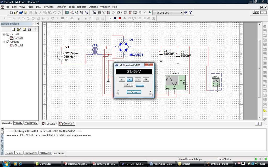
20 Our transformer needed to step down 230Vac to 16Vrms with a current of atleast 3Arms. Hence the transformer ratio is so calculated to be 16Vrms/220Vrms = as shown in the simulation Following the transformer output, the next stage in the AC/DC conversion process involved inverting the negative cycles of the AC input. This process requires the use of a full wave rectifier diode bridge. We determined the required specifications for the bridge rectifier based on the input voltage and current. We determined that our rectifier would have to be able to handle the peak voltage of 22.6V as well as 3 A that the charging circuit would be pulling. We used the MDA 2501 rectifier for simulation purposes. Next we needed to decide the value of the capacitance. The Ac output from the transformer consisted of 16Vrms at 50Hz. We tested for different
21 known values of the capacitor to see how they would affect the output. The current source was 3A which was the maximum current drawn by the charger circuit due to internal current limiting of the voltage regulator. We computed the required capacitor values using the formula: = I= 3A ie the maximum load current of the charging circuit dv= 22.6V-17V, i.e the amplitude of the input signal minus the minimum voltage required by the charging circuit. dt= 1/100Hz, because the frequency of the rectified signal is twice the frequency of the input. C= uf. Since the calculated value is not a common value we choose the next highest value, 5600uf. We choose a higher value as higher capacitor values decrease the ripple voltage. But in Multisim we found a 6800uf capacitor with a better voltage rating than a 5600uf capacitor so we chose it for the simulation purpose. The voltage output from the multimeter and the spectrum analyser output is as shown in the simulation in the next page.

22
23 Charging Circuit General Description The full charger feedback control circuit can be seen in Figure below. This circuit implements a three stage charger algorithm: constant current state, constant voltage full charge state, and constant voltage float charges state. This circuit will require an input voltage of at least 17 volts to output the 14.7V for charging because of the 2V drop across the regulator. The comparator is used to provide feedback of the current that the battery is drawing from the circuit: as the battery charges, the current drawn decreases. The current sensing resistor is used to convert that current into voltage, which can be used to compare to a reference within the circuit. This will be the logic needed for the state switching mechanism. The full charge state will provide 14.7V or 2.45V/Cell on the battery and float charge will provide 13.8V or 2.3V/Cell. The battery will try to draw maximum current, in this case: (14.7V-10.5V)/.1Ohm= 42A (assuming the battery is completely dead) The current limiting of the voltage regulator will force the current to 3A. The charger will continuously pump this 3A until the battery current falls below the limit of 500 ma. This will bring the voltage of the battery above the reference point, therefore causing the comparator to turn on the transistor switch, pulling the output voltage to the float charging level.
24 Complete Charging Circuit module

25 Simulation The simulation was slowly built up piece by piece to ensure proper simulation of the complete circuit, as well as catch any simulation problems that might be encountered. Step I: Testing Voltage Regulation Our circuit will include an LM350, 3-Amp, adjustable voltage regulator, but since the model for this regulator was not available in Multisim, a comparable adjustable regulator was used for simulation purposes. The input to the regulator was chosen to be at least two volts higher above the set
26 output voltage. In the figure above the resistor values were chosen so that the voltage regulator is configured to the output 14.5V DC for testing purposes only. An interesting note, the simulator applies a 1.3V potential between the adjustment and the output pins. This somewhat varies from the specification of the LM350, which tries to maintain 1.25V across the same pins. Using the simulator s voltage across R1, the voltage was calculatedto be 14.5V: Vout = 1.3V + (1.3V/R1)*R2 This was confirmed by the simulation. Step 2: Varying Vout through a Single Switch Controlling the output voltage to the battery is an essential part of multi-stage charging circuitry. Adding a transistor will act as a switch to ground, and therefore vary the equivalent resistance of R4 which will provide control over the voltage regulator. When the switch is turned on, R5 is connected to ground, putting it in parallel with R4. This lowers the equivalent resistance of both resistors, and therefore lowers the voltage across both of them. Since the voltage is lower, the total output voltage is brought down the same amount. The voltage on the first stage needed to be 14.7V or 2.45 V/Cell and during the float state, 13.8V or 2.3V/Cell. The current through R1, R3 and R2 is 1.25V/250Ohms=.005 A as shown in the simulator

27 The output voltages was calculated to be: Transistor State R4 R5 VR4 Vout OFF ON
28 Simulating the circuit the output voltage was measured to be 13.8 and 15.1 V when it was completely off. This.4V difference is due to the fact that the potential difference between the adjusting terminal and the output pin is 1.3 rather than 1.25; therefore producing a larger current, while increasing the output voltage. Another possible reason could be the voltage drop across the transistor which does not completely pull the resistor to ground when it is on, and also has leakage currents.

29 Step 3: Reference Controlled Switch Providing automatic switching based on voltage level was implemented using a comparator. The logical state change happens when the battery reaches a certain potential below the full charging voltage.
30 The current through R1 and R5 was calculated to be 5 ma. Breaking the 250Ohm resistor into 240Ohm resistor in series with a 10Ohm, provides a 50mV reference below the output voltage. This reference is used as the negative input for the comparator, and the battery voltage as the positive input. Whenever the battery charge is greater than the reference point, the comparator turns on the transistor, and therefore lowers the output voltage to the float charger state. This phenomenon was observed as predicted in the simulations above.
31 Step 4: Providing feedback through the current sensing resistor This final step was to build the complete circuit. It proved to be a challenging task. Even though logically the circuit made sense and did not vary significantly from the previous one, we were unable to get the expected output. After trying to appease the simulator for long hours, we came to the conclusion that our analysis is probably correct and that feedback loop through the current sensing resistor R6, added enough complexity to the circuit that the simulator did not provide an accurate answer.
32 Battery Indicator We came up with a very simple design for a voltage monitor. Figure 18 depicts a quad-voltage comparator (LM324) that used to control a simple bar graph meter to indicate the charge condition of the 12-volt lead acid battery. A 5.4-volt reference voltage(d1) is connected to each of the non-inverting inputs of the four comparators and the inverting inputs are connected to successive points along a voltage divider. The LEDsilluminate as the voltage at the inverting terminals exceeds the reference voltage. LED 1turns on at 11 volts, LED 2 turns on at 13 volts, LED 3 turns on at 14 volts, and LED 4 turns on at 14.3 volts.
33 Charging Circuit Module
34 Conclusion A simple lead acid battery charger system was designed successfully. The proposed charger can work in constant voltage or constant current mode although constant voltage mode is the most preferred. The battery charger has many advantages like successful 3-stage charging, over charge protection, battery discharge protection and a simple design. However the battery charger would be difficult to operate in hotter temperatures. Further we can improve the heatsink to dissipate the heat better and also indicators can be designed to indicate bulk charge and float charge states.
35 REFERENCES RV owners forum: Boaters World: Battery Stuff.com: Battery Mart: Battery Minder: PCB Pro.com: Powerstream.com:
ECE 480 Design Team 3: Designing Low Voltage, Low Current Battery Chargers
 Michigan State University Electrical Engineering Department ECE 480 Design Team 3: Designing Low Voltage, Low Current Battery Chargers Application Note Created by: James McCormick 11/8/2015 Abstract: The
SPECIFICATIONS LOW COST 2404R CHARGER
 SPECIFICATIONS LOW COST 2404R CHARGER Totally Automatic Switch-Mode Battery Chargers "Suitable for Gel, Sealed & Wet Lead Acid Batteries" Summary: 24 Volts, 2 Amp Constant Current (Equivalent to 4A tapered
Dismantling the Myths of the Ionic Charge Profiles
 Introduction Dismantling the Myths of the Ionic Charge Profiles By: Nasser Kutkut, PhD, DBA Advanced Charging Technologies Inc. Lead acid batteries were first invented more than 150 years ago, and since
High Efficiency Battery Charger using Power Components [1]
![High Efficiency Battery Charger using Power Components [1]](/thumbs/72/67707899.jpg "High Efficiency Battery Charger using Power Components [1]") APPLICATION NOTE AN:101 High Efficiency Battery Charger using Power Components [1] Marco Panizza Senior Applications Engineer Contents Page Introduction 1 A Unique Converter Control Scheme 1 The UC3906
APPLICATION NOTE AN:101 High Efficiency Battery Charger using Power Components [1] Marco Panizza Senior Applications Engineer Contents Page Introduction 1 A Unique Converter Control Scheme 1 The UC3906
Reference: Photovoltaic Systems, p References: Photovoltaic Systems, Chap. 7 National Electrical Code (NEC), Articles 110,
, Articles 110,") Charge controllers are required in most PV systems using a battery to protect against battery overcharging and overdischarging. There are different types of charge controller design, and their specifications
Charge controllers are required in most PV systems using a battery to protect against battery overcharging and overdischarging. There are different types of charge controller design, and their specifications
SPECIFICATIONS LOW COST 2404S CHARGER
 6033 Shawson Dr., Unit 29, Mississauga Ontario, Canada L5T 1H8, e-mail: info@soneil.com Ph.: 905 565 0360 Fax: 905 565 0352 Visit us on the web at www.soneil.com SPECIFICATIONS LOW COST 2404S CHARGER Totally
SPECIFICATIONS SRL CHARGER
 SONEIL 6033 Shawson Dr., Unit 29, Mississauga Ontario, Canada L5T 1H8, Email: info@soneil.com Ph.: 905 565 0360 Fax: 905 565 0352 Visit us on the web at http://soneil.com SPECIFICATIONS - 2403SRL CHARGER
LM3647 Reference Design User s Manual
 LM3647 Reference Design User s Manual GENERAL DESCRIPTION The LM3647 is a charge controller for Nickel-Cadmium (Ni- Cd), Nickel-Metal Hydride (Ni-MH) or Lithium-Ion (Li-Ion) batteries. The device uses
Power Management Solution: Constant Voltage (CV) Pulse Charging of Hybrid Capacitors
 Pulse Charging of Hybrid Capacitors") VISHAY BCCOMPONENTS www.vishay.com Aluminum Capacitors By Gerald Tatschl ENYCAP TM 196 HVC SERIES GENERAL INFORMATION Rechargeable energy storage solutions are of high interest because of their flexibility,
VISHAY BCCOMPONENTS www.vishay.com Aluminum Capacitors By Gerald Tatschl ENYCAP TM 196 HVC SERIES GENERAL INFORMATION Rechargeable energy storage solutions are of high interest because of their flexibility,
Technical Note. Management of Sealed Lead Acid Batteries in Reliable Small DC Standby Power Supply Systems
 Technical Note Management of Sealed Lead Acid Batteries in Reliable Small DC Standby Power Supply Systems Automation Products Introduction As more and more remote monitoring is installed on sites ranging
SPECIFICATIONS SR CHARGER
 6033 Shawson Dr., Unit 29, Mississauga Ontario, Canada L5T 1H8, Email: info@soneil.com Ph.: 905 565 0360 Fax: 905 565 0352 Visit us on the web at www.soneil.com SPECIFICATIONS - 2409SR CHARGER Totally
12-Batteries and Inverters. ECEGR 452 Renewable Energy Systems
 12-Batteries and Inverters ECEGR 452 Renewable Energy Systems Overview Batteries Lead-Acid Batteries Battery Specifications Battery Charge Controllers Inverters Dr. Louie 2 Batteries Incorporation of a
Open-circuit voltages (OCV) of various type cells:
 of various type cells:") Open-circuit voltages (OCV) of various type cells: Re-Chargeable cells: Lead Acid: 2.10V/cell to 1.95 NiMH and NiCd: 1.20 V/cell Li Ion: 3.60 V/cell Non-re-chargeable (primary) cells: Alkaline: 1.50 V/cell
Open-circuit voltages (OCV) of various type cells: Re-Chargeable cells: Lead Acid: 2.10V/cell to 1.95 NiMH and NiCd: 1.20 V/cell Li Ion: 3.60 V/cell Non-re-chargeable (primary) cells: Alkaline: 1.50 V/cell
ELECTRICAL BATTERIES FOR RENEWABLE ENERGY
 ELECTRICAL BATTERIES FOR RENEWABLE ENERGY Abstract The lead acid battery is the most used in industry. It s advantageous to use because of its low cost. Modern renewable energy systems need batteries to
Coleman Air Diversion Controller Model C40
 Coleman Air Diversion Controller Model C40 Version 2.0 With Extended Diversion Mode Designed for 12 volt battery based systems. The Coleman Air model C40 charge controller is a compact, simple to use controller
Solar Power Energy Harvesting Electrical Integration
 WHITEPAPER Solar Power Energy Harvesting Electrical Integration Contents Introduction... 1 Solar Cell Electrical Characteristics... 2 Energy Harvesting System Topologies... 4 Design Guide... 6 Indoor Single
Specification of Soneil Battery Charger MODEL: 5807SR 60V5A BATTERY CHARGER
 SONEIL INTERNATIONAL LIMITED 3 180 Advance Blvd., Brampton, Ontario, L6T 4J4 Ph.: 905-565-0360 Fax: 905-799-6821 http://www.soneil.com Specification of Soneil Battery Charger MODEL: 5807SR 60V5A BATTERY
SPECIFICATIONS SRM10 24V 0.5A MEDICAL CHARGER
 6033 Shawson Dr., Unit 29, Mississauga Ontario, Canada L5T 1H8, Email: info@soneil.com Ph.: 905 565 0360 Fax: 905 565 0352 Visit us on the web at www.soneil.com SPECIFICATIONS - 2403SRM10 24V 0.5A MEDICAL
EXPERIMENTAL VERIFICATION OF INDUCED VOLTAGE SELF- EXCITATION OF A SWITCHED RELUCTANCE GENERATOR
 EXPERIMENTAL VERIFICATION OF INDUCED VOLTAGE SELF- EXCITATION OF A SWITCHED RELUCTANCE GENERATOR Velimir Nedic Thomas A. Lipo Wisconsin Power Electronic Research Center University of Wisconsin Madison
Service Department. Other Service Items. Battery Basics. How Do Lead Acid Batteries Work? Battery Construction. Service Address
 1 of 5 12/6/2012 11:57 AM Home Contact Us Site Ma About Us RV Specialty Marine Medical Sales Services Customers News Manufacturing American Made Products for RV, Specialty, Marine and Medical Industries
SPECIFICATIONS SR
 6033 Shawson Dr., Unit 29, Mississauga Ontario, Canada L5T 1H8 e-mail: info@soneil.com Ph.: 905 565 0360 Fax: 905 565 0352 Visit us on the web at www.soneil.com SPECIFICATIONS - 4812SR Totally Automatic
SPECIFICATIONS SRF SuperchargerPlus
 SPECIFICATIONS - 2412SRF Totally Automatic Switch-Mode Battery Chargers "Suitable for Gel, Sealed & Wet Lead Acid Batteries" Summary: 24 V, 6Amp Constant Current (equivalent to 12A tapered charger in charging
Specification of Soneil Battery Charger
 SONEIL INTERNATIONAL LIMITED 3 180 Advance Blvd., Brampton, Ontario, L6T 4J4 Ph.: 905-565-0360 Fax: 905-799-6821 http://www.soneil.com Specification of Soneil Battery Charger MODEL: CS3603SR 36V1.2A BATTERY
Powerterm L120C Single Output PSU/Battery Chargers Model C2199A-1 (12V/8A) or Model C2199A-2 (24V/6A)
 or Model C2199A-2 (24V/6A)") A Complete solution for small battery-backed dc instrument power systems. DATASHEET Supply 12Vdc 8A or 24Vdc 6A loads Ideal for RTU s, dataloggers, remote field instrumentation, alarm systems, etc. where
A Complete solution for small battery-backed dc instrument power systems. DATASHEET Supply 12Vdc 8A or 24Vdc 6A loads Ideal for RTU s, dataloggers, remote field instrumentation, alarm systems, etc. where
INTRODUCTION. Specifications. Operating voltage range:
 INTRODUCTION INTRODUCTION Thank you for purchasing the EcoPower Electron 65 AC Charger. This product is a fast charger with a high performance microprocessor and specialized operating software. Please
SPECIFICATIONS CAA Supercharger
 SPECIFICATIONS - 2408CAA Totally Automatic Switch-Mode Battery Chargers "Suitable for Gel, Sealed & Wet Lead Acid Batteries" Summary: 24 V, 4A Constant Current (equivalent to 8A tapered charger in charging
Final Year Project Final Presentation Title: Energy Conversion for low voltage sources.
 Final Year Project Final Presentation Title: Energy Conversion for low voltage sources. Supervisor: Dr.Maeve Duffy Aim of Project The aim of this project was to develop circuits to demonstrate the performance
Signature of the candidate. The above candidate has carried out research for the Masters Dissertation under my supervision.
 DECLARATION I declare that this is my own work and this dissertation does not incorporate without acknowledgement any material previously submitted for a Degree or Diploma in any other University or institute
Ag Features. Multi-Stage Charging. Solar Panel or DC Input. Maximum Power Point Tracking (MPPT) Very Low Power Consumption
 Very Low Power Consumption") Datasheet Ag103 Intelligent Sealed Lead Acid Solar Battery Charger Module Pb 1 Features Multi-Stage Charging Solar Panel or DC Input Maximum Power Point Tracking (MPPT) Very Low Power Consumption Wide
Datasheet Ag103 Intelligent Sealed Lead Acid Solar Battery Charger Module Pb 1 Features Multi-Stage Charging Solar Panel or DC Input Maximum Power Point Tracking (MPPT) Very Low Power Consumption Wide
Coleman Air Diversion Controller Model C40
 Coleman Air Diversion Controller Model C40 Designed for 12 volt battery based systems. The Coleman Air model C40 charge controller is a compact, simple to use controller specifically designed for use with
Lead Acid Batteries Modeling and Performance Analysis of BESS in Distributed Generation
 Murdoch University Faculty of Science & Engineering Lead Acid Batteries Modeling and Performance Analysis of BESS in Distributed Generation Heng Teng Cheng (30471774) Supervisor: Dr. Gregory Crebbin 11/19/2012
THE SOLAR POWERED ANTI-THEFT BAG
 THE SOLAR POWERED ANTI-THEFT BAG Ruchi Mangesh Jadhav 1, Sarika Hari Gaonkar 2, Darshan Kamlesh Khatri 3 Soumya Satish Bangera 4 a ruchimjadhav@gmail.com, b sarikagaonkar01@gmail.com, c darshankk.dk@gmail.com,
Lithium Ion Battery Charger for Solar-Powered Systems
 Lithium Ion Battery Charger for Solar-Powered Systems General Description: The is a complete constant-current /constant voltage linear charger for single cell Li-ion and Li Polymer rechargeable batteries.
DYNAMIC BOOST TM 1 BATTERY CHARGING A New System That Delivers Both Fast Charging & Minimal Risk of Overcharge
 DYNAMIC BOOST TM 1 BATTERY CHARGING A New System That Delivers Both Fast Charging & Minimal Risk of Overcharge William Kaewert, President & CTO SENS Stored Energy Systems Longmont, Colorado Introduction
Application Note CTAN #127
 Application Note CTAN #127 Guidelines and Considerations for Common Bus Connection of AC Drives An important advantage of AC drives with a fixed DC is the ability to connect the es together so that energy
Implementation of a Grid Connected Solar Inverter with Maximum Power Point Tracking
 ECE 4600 GROUP DESIGN PROJECT PROGRESS REPORT GROUP 03 Implementation of a Grid Connected Solar Inverter with Maximum Power Point Tracking Authors Radeon Shamilov Kresta Zumel Valeria Pevtsov Reza Fazel-Darbandi
DESIGN OF HIGH ENERGY LITHIUM-ION BATTERY CHARGER
 Australasian Universities Power Engineering Conference (AUPEC 2004) 26-29 September 2004, Brisbane, Australia DESIGN OF HIGH ENERGY LITHIUM-ION BATTERY CHARGER M.F.M. Elias*, A.K. Arof**, K.M. Nor* *Department
CONTENTS TABLE OF CONTENTS... 1 INTRODUCTION... 2 SEC 1 - SPECIFICATIONS... 3 SEC 2 - DESCRIPTION... 5 SEC 3 - OPERATING INSTRUCTIONS...
 CONTENTS SUBJECT PAGE TABLE OF CONTENTS... 1 INTRODUCTION... 2 SEC 1 - SPECIFICATIONS... 3 SEC 2 - DESCRIPTION... 5 SEC 3 - OPERATING INSTRUCTIONS... 8 SEC 4 - BATTERY CHARGING NOTES... 9 SEC 5 - VERIFICATION
SPECIFICATIONS SRF
 6033 Shawson Dr., Unit 29, Mississauga Ontario, Canada L5T 1H8 e-mail: info@soneil.com Ph.: 905 565 0360 Fax: 905 565 0352 Visit us on the web at www.soneil.com SPECIFICATIONS - 2416SRF Totally Automatic
SPECIFICATIONS SR CHARGER
 6033 Shawson Dr., Unit 29, Mississauga Ontario, Canada L5T 1H8, Email: info@soneil.com Ph.: 905 565 0360 Fax: 905 565 0352 Visit us on the web at http://soneil.com SPECIFICATIONS - 1212SR CHARGER Totally
5A LOW DROPOUT POSITIVE REGULATOR
 5A LOW DROPOUT POSITIVE REGULATOR Features Output Current : 5A Maximum Input Voltage : 12V Adjustable Output Voltage or Fixed 1.8V, 3.3V, 5.0V Current Limiting and Thermal Protection Standard 3Pin Power
Battery Bank for Wind Turbine. Project Proposal Prash Ramani, Marcos Rived TA: Katherine O Kane
 Battery Bank for Wind Turbine Project Proposal Prash Ramani, Marcos Rived TA: Katherine O Kane Table of Contents: 1.0 Introduction.2 1.1 Statement of Purpose 1.1.0 Scope 1.1.1 Purpose 1.2 Objectives 1.2.1
Multiple Input Battery Charger Competitive Value Analysis
 Multiple Input Battery Charger Competitive Value Analysis Group 3 Homework 2 November 11, 2003 Michael Eskowitz ECE Box # 99 Eric Hall ECE Box # 133 Chris Hamman ECE Box # 139 Table of Contents 1 Introduction
BPS-v4 Technical Reference S-CAB 11 volt, 1 amp battery power supply
 BPS-v4 Technical Reference S-CAB 11 volt, 1 amp battery power supply This fourth generation BPS battery power supply is intended for applications requiring up to 1 amp from a small package. Conceptually,
Novel Design and Implementation of Portable Charger through Low- Power PV Energy System Yousif I. Al-Mashhadany 1, a, Hussain A.
 Novel Design and Implementation of Portable Charger through Low- Power PV Energy System Yousif I. Al-Mashhadany 1, a, Hussain A. Attia 2,b 1 Electrical Engineering Dept., College of Engineering, University
Why Ni-Cd batteries are superior to VRLA batteries. Statements and facts
 Why Ni-Cd batteries are superior to VRLA batteries Statements and facts 1. Maintenance Maintenance for VLRA batteries leads to higher costs than for nickelcadmium batteries. 2. Lifetime In practice, the
Simple Free-Energy Devices
 Simple Free-Energy Devices There is nothing magic about free-energy and by free-energy I mean something which produces output energy without the need for using a fuel which you have to buy. Chapter 4:
HIGH VOLTAGE vs. LOW VOLTAGE: POTENTIAL IN MILITARY SYSTEMS
 2013 NDIA GROUND VEHICLE SYSTEMS ENGINEERING AND TECHNOLOGY SYMPOSIUM POWER AND MOBILITY (P&M) MINI-SYMPOSIUM AUGUST 21-22, 2013 TROY, MICHIGAN HIGH VOLTAGE vs. LOW VOLTAGE: POTENTIAL IN MILITARY SYSTEMS
Robots may bepowered by avariety of methods. Some large robots use internal
 Appendix C Batteries Robots may bepowered by avariety of methods. Some large robots use internal combustion engines to generate electricityorpower hydraulic or pneumatic actuators. For a small robot, however,
CONTINUOUS POWER SUPPLY BY SWITCHING THREE SOURCES
 CONTINUOUS POWER SUPPLY BY SWITCHING THREE SOURCES Miss. Khapane Nisha Nanaso 1 1LECTURER, Department of Electronics and Telecommunication, Y.D. Mane Institute of Technology, Kagal. ---------------------------------------------------------------------------***----------------------------------------------------------------------
NorthStar Battery (NSB) Telecom Application Manual
 Telecom Application Manual") NorthStar Battery (NSB) Telecom Application Manual Contents Silver Star Technology TM... 3 1 Introduction... 3 1.1 The Silver Star Technology TM and Semi-Stable Mains... 3 1.2 Discharge Rate... 3 2 Charge...
NorthStar Battery (NSB) Telecom Application Manual Contents Silver Star Technology TM... 3 1 Introduction... 3 1.1 The Silver Star Technology TM and Semi-Stable Mains... 3 1.2 Discharge Rate... 3 2 Charge...
XA4217. Preset 8.4V Charge Voltage with 1% Accuracy
 High Accuracy Linear Li-Lon Battery Charger Features Preset 8.4V Charge Voltage with 1% Accuracy Input Voltage:9-10V DC Pre-Charging, the Charge Current is Programmable Charge Current Up to 1A adjustable
Charging pure lead-tin batteries:
 A guide for CYCLON and Genesis products Kalyan Jana Western Product Support Manager Hawker Energy Products Inc. Warrensburg, MO 64093-9301 (USA) Table of contents LIST OF FIGURES...4 GENERAL...5 BASIC
ATD-5921 RECHARGEABLE 12 VOLT 18 AMP/HOUR JUMP START OWNERS MANUAL
 ATD-5921 RECHARGEABLE 12 VOLT 18 AMP/HOUR JUMP START OWNERS MANUAL 900 PEAK AMPS/400 CRANKING AMPS OF STARTING POWER. STARTS CARS, TRUCKS, RV s AND BOATS WITHOUT THE NEED OF ANOTHER VEHICLE OR AC POWER
SECTION #1 - The experimental design
 Six Lemons in a Series/Parallel Charging a 4.4 Farad Capacitor, NO Load Resistor SECTION #1 - The experimental design 1a. The goal of this experiment is to see what voltage I can obtain with the lemon
In this installment we will look at a number of things that you can do with LEDs on your layout. These will include:
 Introduction The first article in this series, LEDs 101 - The Basics, served to review the characteristics and use of LED lighting in a garden railway environment. It also generated a host of questions
Matching Your Load With Your PV System
 Matching Your Load With Your PV System After A you have determined that PV represents the best way to meet your load, you need to size your system to effectively meet your daily load. In addition to bringing
High Level Design ElecTrek
 High Level Design ElecTrek EE Senior Design November 9, 2010 Katie Heinzen Kathryn Lentini Neal Venditto Nicole Wehner Table of Contents 1 Introduction...3 2 Problem Statement and Proposed Solution...3
Model No.: NHC-01 Smart Charger Module for NiMH Battery Packs (Rev. 2.0)
") Model No.: NHC-01 Smart Charger Module for NiMH Battery Packs (Rev. 2.0) DESCRIPTION The NHC-01 is a professional, processor-controlled charger module for NiMH battery pack for AA and AAA cells (1000 2800
Model No.: NHC-01 Smart Charger Module for NiMH Battery Packs (Rev. 2.0) DESCRIPTION The NHC-01 is a professional, processor-controlled charger module for NiMH battery pack for AA and AAA cells (1000 2800
HX6038 HX
 HX1001 Advanced Linear Charge Management Controller Features Preset 8.4V Charge Voltage with 1% Accuracy Input Voltage: 9V-16V Pre-Charging, the Charge Current is Programmable Charge Current Up to 1A adjustable
Learning Objectives:
 Topic 5.5 High Power Switching Systems Learning Objectives: At the end of this topic you will be able to; recall the conditions under which a thyristor conducts; explain the significance of the following
Lithium battery charging
 Lithium battery charging How to charge to extend battery life? Why Lithium? Compared with the traditional battery, lithium ion battery charge faster, last longer, and have a higher power density for more
Chapter 19: DC Circuits
 Chapter 19: DC Circuits EMF and Terminal Voltage Resistors in Series and in Parallel Kirchhoff s Rules EMFs in Series and in Parallel; Charging a Battery Capacitors in Series and in Parallel RC Circuits
Coleman Air C440-HVM 440 Amp Diversion Controller Version 3.2
 Coleman Air C440-HVM 440 Amp Diversion Controller Version 3.2 With Extended Diversion Mode Page 1 Page 2 Introduction This diversion controller is the result of our many attempts to use the controllers
HOMER OPTIMIZATION BASED SOLAR WIND HYBRID SYSTEM 1 Supriya A. Barge, 2 Prof. D.B. Pawar,
 1 HOMER OPTIMIZATION BASED SOLAR WIND HYBRID SYSTEM 1 Supriya A. Barge, 2 Prof. D.B. Pawar, 1,2 E&TC Dept. TSSM s Bhivrabai Sawant College of Engg. & Research, Pune, Maharashtra, India. 1 priyaabarge1711@gmail.com,
Maintaining the operating temperature of the battery at 20 C to 25 C will maximize its service life and efficiency.
 5.1.3 Reliability In most cases, the reliability of a VLA is better than VRLA cells given similar environments. VLA batteries are also more robust to environmental conditions such as temperature and ripple
BASIC ELECTRICAL MEASUREMENTS By David Navone
 BASIC ELECTRICAL MEASUREMENTS By David Navone Just about every component designed to operate in an automobile was designed to run on a nominal 12 volts. When this voltage, V, is applied across a resistance,
The Physics of the Automotive Ignition System
 I. Introduction This laboratory exercise explores the physics of automotive ignition systems used on vehicles for about half a century until the 1980 s, and introduces more modern transistorized systems.
ICS1702EB. ICS1702 Evaluation Board. Table 1 Cells R6 R8 1 Open Short 2 2.0k 2.0k 3 1.0k 2.0k 4 1.0k 3.0k 5 3.0k 12k 6 2.0k 10k 7 2.0k 12k 8 1.3k 9.
 ICS70EB ICS70 Evaluation Board General Description Galaxy Power, Inc.'s ICS70 Evaluation Board allows quick evaluation of the ICS70 Charge Controller for Nickel-Cadmium and Nickel-Metal Hydride Batteries.
DIRECT TORQUE CONTROL OF A THREE PHASE INDUCTION MOTOR USING HYBRID CONTROLLER. RAJESHWARI JADI (Reg.No: M070105EE)
") DIRECT TORQUE CONTROL OF A THREE PHASE INDUCTION MOTOR USING HYBRID CONTROLLER A THESIS Submitted by RAJESHWARI JADI (Reg.No: M070105EE) In partial fulfillment for the award of the Degree of MASTER OF
DIRECT TORQUE CONTROL OF A THREE PHASE INDUCTION MOTOR USING HYBRID CONTROLLER A THESIS Submitted by RAJESHWARI JADI (Reg.No: M070105EE) In partial fulfillment for the award of the Degree of MASTER OF
ATD-5925 RECHARGEABLE 12 VOLT 18 AMP/HOUR JUMP START WITH BUILT-IN 260 PSI AIR COMPRESSOR OWNERS MANUAL
 ATD-5925 RECHARGEABLE 12 VOLT 18 AMP/HOUR JUMP START WITH BUILT-IN 260 PSI AIR COMPRESSOR OWNERS MANUAL 1000 PEAK AMPS/400 CRANKING AMPS OF STARTING POWER. STARTS CARS, TRUCKS, RV s AND BOATS WITHOUT THE
Autonomously Controlled Front Loader Senior Project Proposal
 Autonomously Controlled Front Loader Senior Project Proposal by Steven Koopman and Jerred Peterson Submitted to: Dr. Schertz, Dr. Anakwa EE 451 Senior Capstone Project December 13, 2007 Project Summary:
Coleman Air Diversion Controller Model C160M Version 4.3 With Extended Diversion Mode
 Coleman Air Diversion Controller Model C160M Version 4.3 With Extended Diversion Mode Page 1 Introduction This diversion controller is the result of our many attempts to use the controllers currently on
BATTERY CHARGING SYSTEMS
 BATTERY CHARGING SYSTEMS BATTERIES ARE CHARGED BY APPLYING A HIGH ENOUGH VOLTAGE TO THEM. BUT THE RATE OF CHARGE IS NOT CONSTANT. IN THE FIRST SPLIT SECOND, THE VERY LIGHT ELECTRONS FROM THE CHARGING SOURCE
DYNAMO & ALTERNATOR - B FIELD LOGIC PROBE.
 DYNAMO & ALTERNATOR - B FIELD LOGIC PROBE. H. HOLDEN 2010. Background: This article describes the development and construction of a simple diagnostic tool - a self powered logic probe, to assess the voltage
AUTO CHARGE 4000 MODEL #: AUTOMATIC DUAL OUTPUT BATTERY CHARGER INSTRUCTION MANUAL. Ph: Fax:
 INSTRUCTION MANUAL AUTO CHARGE 4000 AUTOMATIC DUAL OUTPUT BATTERY CHARGER MODEL #: 091-89-12 INPUT: 120 Volt, 50/60 Hz, 8 Amps OUTPUT BATTERY CHARGER: 40 Amps OUTPUT BATTERY SAVER: 5 Amps File: IM_091-89-12_reve.indd
Design and Implementation of an Automatic Power Supply from Four Different Source Using Microcontroller
 International Journal of Electrical and Electronic Science 2017; 4(5): 40-46 http://www.aascit.org/journal/ijees ISSN: 2375-2998 Design and Implementation of an Automatic Power Supply from Four Different
KIT-STCS60D KIT-STCS100D Solar Suitcase 60W and 100W Owner s Manual
 KIT-STCS60D KIT-STCS100D Solar Suitcase 60W and 100W Owner s Manual RNG Group Inc. (Renogy) 14288 Central Ave., Suite A Chino, CA 91710 1-800-330-8678 Product Description The Renogy Solar Suitcases combine
BATTERY CHARGERS.
 BATTERY CHARGERS Battery Charging Batteries used on rolling stock are either lead acid or nickel cadmium. Both types are available in sealed form so that water or gel does not need to be added. Batteries
Real-time Bus Tracking using CrowdSourcing
 Real-time Bus Tracking using CrowdSourcing R & D Project Report Submitted in partial fulfillment of the requirements for the degree of Master of Technology by Deepali Mittal 153050016 under the guidance
A Transient Free Novel Control Technique for Reactive Power Compensation using Thyristor Switched Capacitor
 A Transient Free Novel Control Technique for Reactive Power Compensation using Thyristor Switched Capacitor 1 Chaudhari Krunal R, 2 Prof. Rajesh Prasad 1 PG Student, 2 Assistant Professor, Electrical Engineering
Battery Charging Options for Portable Products by David Brown Senior Manager of Applications Engineering Advanced Analogic Technologies, Inc.
 Technical Article Battery Charging Options for Portable Products by David Brown Senior Manager of Applications Engineering Advanced Analogic Technologies, Inc. Few components in portable system design
The Traveler Series TM : Adventurer
 The Traveler Series TM : Adventurer 30A PWM Flush Mount Charge Controller w/ LCD Display 2775 E. Philadelphia St., Ontario, CA 91761 1-800-330-8678 Version: 3.4 Important Safety Instructions Please save
The Traveler Series: Adventurer
 The Traveler Series: Adventurer RENOGY 30A Flush Mount Charge Controller Manual 2775 E. Philadelphia St., Ontario, CA 91761 1-800-330-8678 Version: 2.2 Important Safety Instructions Please save these instructions.
Investigations into methods of measuring the state of health of a nickel-cadmium Industrial Battery
 Investigations into methods of measuring the state of health of a nickel-cadmium Industrial Battery Anthony Green, SAFT, France AUTHOR BIOGRAPHICAL NOTES Anthony Green graduated from the University of
LBI-31864D. Mobile Communications VEHICULAR CHARGER UNIT 19B801507P1, P4. Printed in U.S.A. Maintenance Manual
 LBI-31864D Mobile Communications VEHICULAR CHARGER UNIT 19B801507P1, P4 Maintenance Manual Printed in U.S.A. TABLE OF CONTENTS Page SPECIFICATIONS.................................................... 1
Semi-Active Suspension for an Automobile
 Semi-Active Suspension for an Automobile Pavan Kumar.G 1 Mechanical Engineering PESIT Bangalore, India M. Sambasiva Rao 2 Mechanical Engineering PESIT Bangalore, India Abstract Handling characteristics
Solar Based Up Convertor Handles Remote Sensors
 Solar Based Up Convertor Handles Remote Sensors This project is an up-convertor with a mix of functions. This gadget essentially converts a low voltage source to a higher voltage source. Usually you can
Dual power flow Interface for EV, HEV, and PHEV Applications
 International Journal of Engineering Inventions e-issn: 2278-7461, p-issn: 2319-6491 Volume 4, Issue 4 [Sep. 2014] PP: 20-24 Dual power flow Interface for EV, HEV, and PHEV Applications J Ranga 1 Madhavilatha
INSTRUCTION MANUAL Model 1743B
 Test Equipment Depot - 800.517.8431-99 Washington Street Melrose, MA 02176 TestEquipmentDepot.com INSTRUCTION MANUAL Model 1743B 0-35 V, 0-6 A DC POWER SUPPLY With Dual 4-Digit LED Displays TEST INSTRUMENT
INDIA S FIRST 4 Star Rated Technology Inverter
 INDIA S FIRST 4 Star Rated Technology Inverter 89.57* DC-AC Label Period: 11th Aug, 2014-31st Dec, 2016 Low energy consumption Energy efficient More back up Low running cost DC Bus Voltage Waveform : Inverters
Design Features: User Manual. 1. PFC function. 2. LCD remote control. 3. Battery temperature sensor function.
 User Manual Design Features: 1. PFC function. except BC-1215HT / BC-2407HT 2. LCD remote control. BC-1215HT / BC-2407HT 3. Battery temperature sensor function. 4. Tri-LED color indicator for different
Manual Installation & Operation
 Manual Installation & Operation Model: NCxxLxx 12A or 30A Solid State Solar Charging Regulator and 12A Load Controller. 231 Patent #: 5,642,030 Applies Page 1 Warnings When Installing, connect grounds,
APPLICATION NOTE TESTING PV MICRO INVERTERS USING A FOUR QUADRANT CAPABLE PROGRAMMABLE AC POWER SOURCE FOR GRID SIMULATION. Abstract.
 TESTING PV MICRO INVERTERS USING A FOUR QUADRANT CAPABLE PROGRAMMABLE AC POWER SOURCE FOR GRID SIMULATION Abstract This application note describes the four quadrant mode of operation of a linear AC Power
CONSONANCE CN3051A/CN3052A. 500mA USB-Compatible Lithium Ion Battery Charger. General Description: Features: Pin Assignment.
 CONSONANCE 500mA USB-Compatible Lithium Ion Battery Charger CN3051A/CN3052A General Description: The CN3051A/CN3052A is a complete constant-current /constant voltage linear charger for single cell Li-ion
High-Tech Solar System
 PRODUCT EVALUATION High-Tech Solar System Like its new HPV22B counterpart, Heliotrope s new HPV30 controller incorporates an on/off switch, so the solar panels can be turned off. The HVP30 is specifically
SL Series Application Notes. SL Series - Application Notes. General Application Notes. Wire Gage & Distance to Load
 Transportation Products SL Series - Application Notes General Application Notes vin 2 ft. 14 AWG The SL family of power converters, designed as military grade standalone power converters, can also be used
OPERATING INSTRUCTIONS
 Manual No LI-4159-MIL OPERATING INSTRUCTIONS OPERATING INSTRUCTIONS NAVY BATTERY CHARGER / ANALYZER P/N 4159-MIL MODEL CA-1550-MIL NSN: 4920-01-498-2543 Issued By: LamarTechnologies LLC 14900 40th Ave.
FlexCharger Battery Chargers
 FlexCharger Battery Chargers Operating Instructions Definitions (as used in these instructions) Flooded Battery Lead-acid battery with liquid electrolyte that requires open-venting and regular water replacement.
CE3152 Series. Standalone Linear LiFePO4 battery charger with Thermal Regulation INTRODUCTION: FEATURES: APPLICATIONS: PIN CONFIGURATION:
 Standalone Linear LiFePO battery charger with Thermal Regulation Series INTRODUCTION: The is a complete constantcurrent constantvoltage linear charger for single cell LiFePO batteries. It s SOT package