DYNAMO & ALTERNATOR - B FIELD LOGIC PROBE.
|
|
|
- Rolf Williams
- 6 years ago
- Views:
Transcription
1 DYNAMO & ALTERNATOR - B FIELD LOGIC PROBE. H. HOLDEN Background: This article describes the development and construction of a simple diagnostic tool - a self powered logic probe, to assess the voltage regulator function and the field or rotor coil drive in an automotive dynamo or alternator system. In the early days of digital electronics it was recognised that a simple cheap tool could help a technician determine if a logic voltage level, typically at the output of some digital IC, was high, or low or, or switching between these two states at some high frequency that could not be visualised without an oscilloscope. Generally these probes had 3 LED s, one for a high voltage level (usually 5 volts), one for a low level and another which blinked on and off, at some easily visible rate, if the voltage was switching very rapidly between high and low levels. This article explains how this same basic idea can be applied to the dynamo or alternator charging system thereby creating a helpful workshop tool. The functionality of both the dynamo and the alternator voltage regulators have been explained in the other articles on this website, relating to Alternators vs Dynamos and Electronic Replacements for the Lucas RB106. To briefly recap, the switching of the coils (either the dynamo field winding or alternator rotor winding) across the power supply voltage controls the average coil current and therefore the B field (magnetic field). Voltage regulation is achieved because the B field controls the output voltage and the voltage regulator device controlling the coil s switching cycle is in a negative feedback loop with the dynamo or alternator s output voltage which is the sensed variable. To make the feedback loop concept clearer, one can regard the alternator or dynamo as a device which has a current input (current to the rotor or field coil) and as a consequence a voltage output (the output from the armature or diode pack in the alternator). Symbolically then the dynamo or alternator can be regarded as a current to voltage converter and the voltage output power boosted from an external power source (mechanical rotation). The mechanical power is derived from the car s engine and transformed to electrical power and delivered at some rate in Joules per seconds of power. The dynamo or alternator system could be represented by the system diagram below. This negative feedback concept is outlined in figure 1. Basically the voltage regulator unit switches voltage across the field coil (or rotor) to create the B field. This process continues until the sensed voltage at the negative input of the comparator system exceeds the reference value, in the typical automotive application this is 14.2 volts. This switches off the voltage drive to the field coil, lowering the average field current so the unit s output voltage falls. This creates a cycle which repeats over and over so that the output voltage
 of dynamo or alternator output voltages and current loading.")
2 remains close to a stable value and varies only with a small amplitude around the reference voltage value. In all negative feedback loops the system remains under feedback control only over a range (dynamic range) of dynamo or alternator output voltages and current loading. We will now refer to the alternator or dynamo as the generator to suggest a unit which includes both types of machine. In other words there is a limited dynamic range of operation where the regulator is switching. For example if the rpm is too slow and the generator cannot produce 14.2 volts, the voltage regulator produces an uncontrolled full on voltage drive to the field coil or rotor. Likewise when the generator is overloaded (due to the finite internal resistance of the armature or stator & diodes in the alternator) the 14.2 volt output is not exceeded and therefore the voltage regulator also drives the field or rotor coil with a full on voltage. Also in fault conditions there may be no drive or continuous voltage drive to the field or rotor coil. From this we can conclude: When the generator is working properly within a mid range rpm and with medium current loading (and therefore running within its normal dynamic range of operation) then a switching voltage should be present across the field coil or rotor coil. Absence of the switching voltage under these circumstances therefore indicates a failure or fault condition. In addition there will reach a point with high current loads, near the generator s maximum output capacity, where the switching stops and the field coil or rotor is being driven by a continuous voltage in an attempt to maintain the specified voltage output.

3 If there is a continuos voltage present across the field coil or rotor coil (in the mid range rpm test condition say engine = 2000 rpm and modest load say headlamps on low beam) then this indicates a failure to produce adequate output due to an open circuit field coil or rotor, or shorted turns such that an inadequate B field is produced. This can be checked if required by measuring the DC resistance of the rotor or field coil with a simple Ohm meter and comparing it with the specifications or a known good unit. If this is ok then attention can be turned to the armature, commutator and brushes and cut-out contacts in the dynamo system or the rectifier pack in the alternator system. If there is low to zero voltage drive on the field coil (or rotor) then suspect the voltage regulator contacts in the conventional dynamo system or the electronic regulator in the alternator system which passes the current to this coil. The point under a heavy load current at which the switching system stops and a continuous field (or rotor) voltage drive occurs, is indicative of the general electrical condition of the generator. Assuming the B field has reached its maximum normal value (there is no field coil or rotor coil problem) then this point is indicative of the armature and commutator and brush condition in the dynamo and in the alternator the condition of the stator windings and rectifier pack. FAULT FINDING A DYNAMO OR ALTERNATOR SYSTEM: The field/rotor coil connection could be monitored with a meter however this will not indicate definite switching voltages only average voltages. Also a lamp or an LED could be connected across the field or rotor coil connections, but due to the switching frequency being above 35 to 40 Hz the flicker is not easily seen due to the flicker fusion frequency of human vision. Ideally to display the switching events one would connect an oscilloscope across the field coil or alternator rotor however this can be inconvenient in the workshop and not easy for those unfamiliar with their operation. Therefore to solve this problem and have a simple workshop diagnostic tool the following B FIELD LOGIC PROBE made from inexpensive parts was designed:
4 Description of operation: The circuit derives its power from the field (or rotor coil) drive voltage and this is regulated down to 5 volts by the 78L05 regulator. Due to the self powering and two wire connection the probe can be applied to either the dynamo or alternator field/rotor coils with the same results in negative ground cars. (It can also be applied to positive ground cars with dynamos if the clip is connected to the F connection and the probe tip to earth instead). The input diode protects the unit from voltage transients swinging below the earth clip potential. These can occur with the electromechanical regulators. This diode also protects the unit from inadvertent reversed polarity connection. The 16V zener diode limits the input voltage should it be higher than this with voltage transients so as to protect the 78L05. When the input voltage exceeds around 7 volts the BC337 conducts triggering the 74LS93 counter which simply contains a chain of flip flops. With a switching voltage crossing this 7 volt threshold value regularly, as it does with normal regulator switching, the 74LS93 is repeatedly toggled and its first flip flop divides the frequency in half. When the frequency is stable this produces a square wave voltage present on pin 1 & 12. If the frequency is variable there is still an alternating voltage on pin 1 & 12 albeit not a perfect square wave. The presence of the square wave or switching voltage is detected by the AC coupled rectifier system using two 1N5711 diodes which produce close to a 4 volt DC level, provided there is output from the first flip flop. If the first flip flop stops toggling then the voltage on pin 1 &12 will either be high (near 5V) or low depending on which state this first flip flop stops in. Due to the AC coupling (via the 1uF capacitor) the state that the flip flop stops in is not important. If there is no flip flop toggling the rectified voltage decays to zero as the one Meg Ohm resistor discharges the other 1uF filter capacitor. The operational amplifiers are biased to one volt, so when switching signal is present the rectified voltage exceeds this value and pin 1 of the TLC272 is high (5V) and pin 7 is low near 0 volts. This situation reverses if there is no flip flop toggling and no switching signal. As a result pin 2 of the 74LS00 remains high with a switching signal present and this allows another signal AC/8 to be gated through via pin 1 of the 74LS00 and to drive the blue LED via the negated Or gate system causing the LED to flash. (Note that a NAND gate is equivalent to an OR gate with negated or inverted inputs- De Morgan s Theorem). This LED flashing signal represents the output from two other flip flops in the 74LS93 and is the probe s input frequency (or the field coil s switching frequency) divided by 8. Therefore if the field coil s switching frequency is 40Hz the LED will be flashing at 5 Hz which is very easy to see visually. In addition, if ever required, an AC/16 (or 1/16 th the input frequency) is available on pin 11 of the 74LS93 in lieu of the AC/8 connection in the case of an extremely rapidly switching alternator rotor drive so as to divide the rate by 16, but it will unlikely be required. If there is no switching detected, then pin 7 of the TLC272 is high and pin 1 low. This blocks the AC/8 signal on pin 8 of the 74LS93. This is required because the output flip flop on this pin could have stopped
5 in a high or low state. The high on pin 12 of the 74LS00 now allows the scaled down input voltage from the probe tip applied to pin 13 to pass via the OR gate system to the LED. The voltage is scaled by the 1k5 and 220 ohm resistors so that the LED will light if the input voltage is over 8 to 10 volts which indicates if the field coil in the dynamo is driven by a continuos on voltage. The Lucas dynamo field coil is pulled towards and to the positive supply voltage by the contacts in the regulator unit. However in the case of most alternator systems the regulator output stage pulls the rotor coil connection towards and to earth (negative). Therefore using this probe with the ground clip connected to the car s ground, the switching function detection won t be affected, however the LED function for continuous voltage will be reversed, in that the LED will be illuminated with a low voltage across the field coil and will extinguish with a continuous voltage applied to the coil. This is shown below.this connection might be handy as the thin probe tip may possibly pass through a vent hole in the alternator rear casing to connect to the regulator body which is the F connection, for example with the 14TR and 19TR Lucas regulators. The photos below show the prototype probe. The first photo shows the inside of the prototype unit:


6 The photo below shows the end view looking at the blue LED:
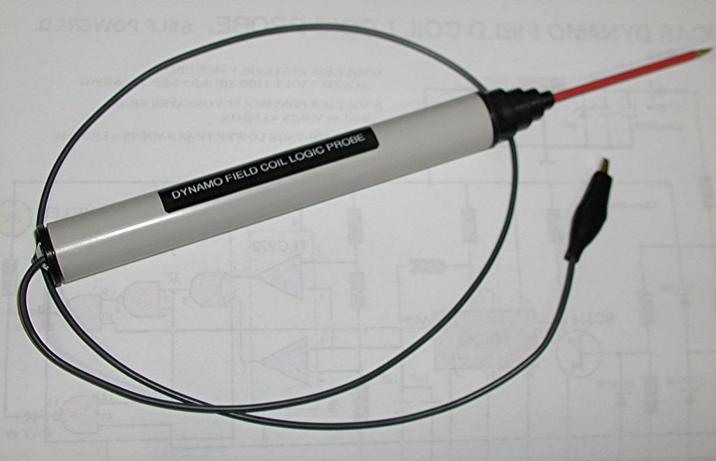
7 The final photo shows a completed probe: *************************************************************************************
3. OPERATION 2.1. RESTRAINT CIRCUIT 2.6. INDICATING CIRCUIT 2.2. OPERATING CIRCUIT 2.7. SURGE PROTECTION CIRCUIT 2.3.
 41-348.1H Type SA-1 2.1. RESTRAINT CIRCUIT The restraint circuit of each phase consists of a center-tapped transformer, a resistor, and a full wave rectifier bridge. The outputs of all the rectifiers are
2.0 CONSTRUCTION 3.0 OPERATION. SA-1 Generator Differential Relay - Class 1E 2.5 TRIP CIRCUIT
 41-348.11C SA-1 Generator Differential Relay - Class 1E 2.0 CONSTRUCTION The type SA-1 relay consists of: Restraint Circuit Sensing Circuit Trip Circuit Surge Protection Circuit Operating Circuit Amplifier
Unit AE01K Knowledge of Locating and Correcting Simple Electrical Faults in the Automotive Workplace
 Assessment Requirements Unit AE01K Knowledge of Locating and Correcting Simple Electrical Faults in the Automotive Workplace Content: Basic electrical principles a. Explain the direction of current flow
Unit 32 Three-Phase Alternators
 Unit 32 Three-Phase Alternators Objectives: Discuss the operation of a three-phase alternator. Explain the effect of rotation speed on frequency. Explain the effect of field excitation on output voltage.
Electronic Dynamo Regulator INSTRUCTION MANUAL. COPYRIGHT 2015 CLOVER SYSTEMS All Rights Reserved
 DR310 TM Electronic Dynamo Regulator INSTRUCTION MANUAL COPYRIGHT 2015 CLOVER SYSTEMS All Rights Reserved INTRODUCTION The Clover Systems DR310 is an allelectronic voltage and current regulator for dynamos
Electronic Dynamo Regulator INSTRUCTION MANUAL. COPYRIGHT 2014 CLOVER SYSTEMS All Rights Reserved
 DRM TM DRM-HP TM Electronic Dynamo Regulator INSTRUCTION MANUAL COPYRIGHT 2014 CLOVER SYSTEMS All Rights Reserved INTRODUCTION The Clover Systems DRM is a state-of-the art all-electronic voltage and current
INSTITUTE OF AERONAUTICAL ENGINEERING Dundigal, Hyderabad
 INSTITUTE OF AERONAUTICAL ENGINEERING Dundigal, Hyderabad - 500 043 MECHANICAL ENGINEERING ASSIGNMENT Name : Electrical and Electronics Engineering Code : A40203 Class : II B. Tech I Semester Branch :
Handout Activity: HA773
 Charging system HA773-2 Handout Activity: HA773 Charging system The charging system allows for a means to recharge the battery and allow for electrical usage of components in the vehicle. The charging
INDEX Section Page Number Remarks
 INDEX Section Page Number Remarks Synchronous Alternators 2 4 General Fault Finding Capacitors 5 6 Fault Finding & Testing Diodes,Varistors, EMC capacitors & Recifiers 7 10 Fault Finding & Testing Rotors
Electrical Energy and Power Ratings
 Section 1 - From the Wall Socket Electrical Energy and ower Ratings Batteries and the mains are sources of electrical energy. Electrical appliances can then convert this into other forms of energy. e.g.
C capacitance, 91 capacitors, codes for, 283 coupling, polarized and nonpolarized,
 Index Numbers and Symbols 555 timer, 164 166 making sound using, setting output speed of, 166 167 using for reaction game speed, 260 261 μf (microfarad), 92 Ω (ohms), 7, 70 A A (amperes), 7 AC (alternating
Armature Reaction and Saturation Effect
 Exercise 3-1 Armature Reaction and Saturation Effect EXERCISE OBJECTIVE When you have completed this exercise, you will be able to demonstrate some of the effects of armature reaction and saturation in
THE DISTRIBUTOR TEST MACHINE for 25D and 45D series distributors:
 THE DISTRIBUTOR TEST MACHINE for 25D and 45D series distributors: Dr. H. Holden Jan 2015. Introduction: The machine shown above was constructed to test 25D and 45D Lucas distributors and their variations
The Physics of the Automotive Ignition System
 I. Introduction This laboratory exercise explores the physics of automotive ignition systems used on vehicles for about half a century until the 1980 s, and introduces more modern transistorized systems.
Learning Objectives:
 Topic 5.5 High Power Switching Systems Learning Objectives: At the end of this topic you will be able to; recall the conditions under which a thyristor conducts; explain the significance of the following
Electronic Dynamo Regulator INSTRUCTION MANUAL. COPYRIGHT 2014 CLOVER SYSTEMS All Rights Reserved
 DRM TM DRM-HP TM Electronic Dynamo Regulator INSTRUCTION MANUAL COPYRIGHT 2014 CLOVER SYSTEMS All Rights Reserved INTRODUCTION The Clover Systems DRM is a state-of-the art all-electronic voltage and current
Chapter 5: DC Motors. 9/18/2003 Electromechanical Dynamics 1
 Chapter 5: DC Motors 9/18/2003 Electromechanical Dynamics 1 Reversing the Rotation Direction The direction of rotation can be reversed by reversing the current flow in either the armature connection the
EXPERIMENTAL VERIFICATION OF INDUCED VOLTAGE SELF- EXCITATION OF A SWITCHED RELUCTANCE GENERATOR
 EXPERIMENTAL VERIFICATION OF INDUCED VOLTAGE SELF- EXCITATION OF A SWITCHED RELUCTANCE GENERATOR Velimir Nedic Thomas A. Lipo Wisconsin Power Electronic Research Center University of Wisconsin Madison
1 THE WOLVERTON SYSTEM OF TRAIN LIGHTING.
 1 THE WOLVERTON SYSTEM OF TRAIN LIGHTING. The Wolverton equipment is a single battery system utilising a plain shunt wound dynamo. The dynamo is controlled by an automatic field regulator which senses
BASIC ELECTRICAL MEASUREMENTS By David Navone
 BASIC ELECTRICAL MEASUREMENTS By David Navone Just about every component designed to operate in an automobile was designed to run on a nominal 12 volts. When this voltage, V, is applied across a resistance,
Understanding The HA2500's Horiz Driver Test
 Understanding The HA2500's Horiz Driver Test Horizontal output stage symptoms and component failures are often caused by problems in the horizontal driver stage. The horizontal driver stage is seldom suspected,
The Starter motor. Student booklet
 The Starter motor Student booklet The Starter motor - INDEX - 2006-04-07-13:20 The Starter motor The starter motor is an electrical motor and the electric motor is all about magnets and magnetism: A motor
CD-20A Sample Probe Controller User Manual
 CLIF MOCK CD-20A Sample Probe Controller User Manual Class I Groups C and D Hazardous Locations Manual No. 2350753-01, Rev. 02 Symbols and Terms Used in this Manual Important Safety Information! WARNING:
Features IN THIS CHAPTER
 CHAPTER THREE 3Special Features IN THIS CHAPTER Motor Braking Regeneration Solutions Sharing the Power Bus: V Bus+ and V Bus- Current Foldback (I T Limit) Front Panel Test Points Resolver Alignment ➂ Special
Battery Power Inverters
 Battery Power Inverters Renogy 500W 1000W 2000W Pure Sine Wave Inverter Manual 2775 E. Philadelphia St., Ontario, CA 91761 1-800-330-8678 1 Version 1.4 Important Safety Instructions Please save these instructions.
SALDET SALES & SERVICE, INC. CLINTON TOWNSHIP, MICHIGAN
 Form 1254 BRAKETRON Electronic Motor Brake Instructions SALDET SALES & SERVICE, INC. CLINTON TOWNSHIP, MICHIGAN TABLE OF CONTENTS SECTION TITLE PAGE I. Introduction 1 II. Specifications 1 III. Principles
Installation Instructions
 Quick-Mount Visual Instructions for Quick-Mount Visual Instructions 1. Rotate the damper to its failsafe position. If the shaft rotates counterclockwise, mount the CCW side of the actuator out. If it rotates
SECTION M. ELECTRICAL. Section Description Page No.
 SECTION M. ELECTRICAL. Section Description Page No. M.1 General Page 2 M.2 Alternator Page 2 M.3 Battery Page 7 M.4 Hazard Warning System Page 7 M.5 Brake Fail Warning System Page 8 M.6 Seat Belt Warning
ALTERNATOR DE-EXCITATION WITH K1 AND K2 ON ANALOGUE
 Application Guidance Notes: Technical Information from Cummins Generator Technologies AGN 023 AVR Features ALTERNATOR DE-EXCITATION WITH K1 AND K2 ON ANALOGUE AVRs On STAMFORD alternators, analogue AVR
An High Voltage CMOS Voltage Regulator for automotive alternators with programmable functionalities and full reverse polarity capability
 L. Fanucci, G. Pasetti University of Pisa P. D Abramo, R. Serventi, F. Tinfena Austriamicrosystems P. Tisserand, P. Chassard, L. Labiste - Valeo An High Voltage CMOS Voltage Regulator for automotive alternators
ELECTRICITY: INDUCTORS QUESTIONS
 ELECTRICITY: INDUCTORS QUESTIONS No Brain Too Small PHYSICS QUESTION TWO (2017;2) In a car engine, an induction coil is used to produce a very high voltage spark. An induction coil acts in a similar way
Atlas ESR and ESR + Equivalent Series Resistance and Capacitance Meter. Model ESR60/ESR70. Designed and manufactured with pride in the UK.
 GB60/70-9 Atlas ESR and ESR + Equivalent Series Resistance and Capacitance Meter Model ESR60/ESR70 Designed and manufactured with pride in the UK User Guide Peak Electronic Design Limited 2004/2016 In
C.E. Niehoff & Co. C703/C703A and C706 Alternators Troubleshooting Guide CAUTION. Testing Guidelines. Hazard Definitions WARNING.
 C.E. Niehoff & Co. C703/C703A and C706 Alternators Troubleshooting Guide WARNING Before troubleshooting any CEN products, the service technician should: read, understand, and agree to follow all information
ALTERNATOR REQUESTED INFORMATION. Vehicles With Dual Generator [ Engine Mount - LH ] 2007 Ford Pickup 6.0L Eng F350 Super Duty
![ALTERNATOR REQUESTED INFORMATION. Vehicles With Dual Generator [ Engine Mount - LH ] 2007 Ford Pickup 6.0L Eng F350 Super Duty](/thumbs/72/66590437.jpg "ALTERNATOR REQUESTED INFORMATION. Vehicles With Dual Generator [ Engine Mount - LH ] 2007 Ford Pickup 6.0L Eng F350 Super Duty") ALTERNATOR 2007 Ford Pickup 6.0L Eng F350 Super Duty REQUESTED INFORMATION Vehicles With Dual Generator [ Engine Mount - LH ] Fig 1: Rotating Drive Belt Tensioner Clockwise 1. Remove the accessory drive
ALTERNATOR 2007 Ford Pickup 6.0L Eng F350 Super Duty REQUESTED INFORMATION Vehicles With Dual Generator [ Engine Mount - LH ] Fig 1: Rotating Drive Belt Tensioner Clockwise 1. Remove the accessory drive
Page 1. Design meeting 18/03/2008. By Mohamed KOUJILI
 Page 1 Design meeting 18/03/2008 By Mohamed KOUJILI I. INTRODUCTION II. III. IV. CONSTRUCTION AND OPERATING PRINCIPLE 1. Stator 2. Rotor 3. Hall sensor 4. Theory of operation TORQUE/SPEED CHARACTERISTICS
ALTERNATOR - HITACHI
 ALTERNATOR - HITACHI 1986 Isuzu Trooper II 1986 Alternators & Regulators HITACHI ALTERNATORS Isuzu DESCRIPTION Hitachi alternators are conventional 3-phase, self-rectifying alternators. Three positive
Powerframes - Power Electronics
 Powerframes - Power Electronics 70 series The study of power electronic devices, motor drives and circuits is an essential part of any course on power electrical systems. The Series 70 Power Electronics
Electric cars: Technology
 In his lecture, Professor Pavol Bauer explains all about how power is converted between the various power sources and power consumers in an electric vehicle. This is done using power electronic converters.
Installation Instructions
 Quick-Mount Visual Instructions for Mechanical Installation Quick-Mount Visual Instructions 1. Rotate the damper to its failsafe position. If the shaft rotates counterclockwise, mount the CCW side of the
Servo and Proportional Valves
 Servo and Proportional Valves Servo and proportional valves are used to precisely control the position or speed of an actuator. The valves are different internally but perform the same function. A servo
NEW ZEALAND POST OFFICE NEGATIVE 50V D.C. TO POSITIVE 50V D.C. SUPPLY NOTES PR 2157 ISSUE 1 APRIL 1977
 NEW ZEALAND POST OFFICE NEGATIVE 50V D.C. TO POSITIVE 50V D.C. SUPPLY NOTES PR 2157 ISSUE 1 APRIL 1977 1. GENERAL. 1.1 These PR notes supersede notes PR 2133 and should only be used in conjunction with
In the first part of this series on
 by Mike Van Dyke In the first part of this series on diagnosing ECUs, we went over some basic visual diagnosis of common failures. In this, the second part of the series, we re going to go over some basic
The function of this Dynamic Active Probe has divided into three preferences on the screen main Menus:
 1.0 Introduction: This probe is designed to provide an additional help to automotive technicians in trouble shooting of electrical circuits problems in the car. Apart from using the normal multi tester,
World Scientific Research Journal (WSRJ) ISSN: Multifunctional Controllable and Detachable Bicycle Power Generation /
 ISSN: Multifunctional Controllable and Detachable Bicycle Power Generation /") World Scientific Research Journal (WSRJ) ISSN: 2472-3703 www.wsr-j.org Multifunctional Controllable and Detachable Bicycle Power Generation / Charging Device Yunxia Ye School of North China Electric Power
World Scientific Research Journal (WSRJ) ISSN: 2472-3703 www.wsr-j.org Multifunctional Controllable and Detachable Bicycle Power Generation / Charging Device Yunxia Ye School of North China Electric Power
Yaskawa Electric America Unit Troubleshooting Manual Section One: Introduction & Checks Without Power GPD 506/P5 and GPD 515/G5 (0.
 Yaskawa Electric America Unit Troubleshooting Manual Section One: Introduction & Checks Without Power GPD 506/P5 and GPD 515/G5 (0.4 ~ 160kW) Page 1 Introduction This manual is divided into three sections:
Electric Motor Controls BOMA Pre-Quiz
 Electric Motor Controls BOMA Pre-Quiz Name: 1. How does a U.P.S. (uninterruptable power supply) work? A. AC rectified to DC batteries then inverted to AC B. Batteries generate DC power C. Generator, batteries,
AUTOMOTIVE MAINTENANCE TECHNOLOGY SUBJECT : AUTOTRONIC 2 TITLE: TRANSISTORISED IGNITION WITH HALL GENERATOR TI-H
 Transistorized ignition with Hall generator TI-H In addition to the breaker-triggered transistorized ignition system (TI-B), there are two other versions of transistorized ignition with Hall triggering
APPLICATION NOTES VALVE CHECKER M
 APPLICATION NOTES VALVE CHECKER M040-120-001 1 of 16 CONTENTS Chapter Title Page 1. Description 3 2. Specification 7 3. Connecting to valve and plant 8 4. Plant mode operation (in line) 9 5. Checker mode
Application Engineering
 Application Engineering February, 2009 Copeland Digital Compressor Controller Introduction The Digital Compressor Controller is the electronics interface between the Copeland Scroll Digital Compressor
Ford Scorpio 95+ Charging System
 Functional Overview of the Ford Scorpio 95+ Charging System Introduction All models of Ford Scorpio 95+, utilise an and charging system. The alternator is spun around by the engine, this provides electrical
Permanent Magnet DC Motor Operating as a Generator
 Exercise 2 Permanent Magnet DC Motor Operating as a Generator EXERCIE OBJECTIVE When you have completed this exercise, you will be familiar with the construction of permanent magnet dc motors as well as
Lab #1: Electrical Measurements I Resistance
 Lab #: Electrical Measurements I esistance Goal: Learn to measure basic electrical quantities; study the effect of measurement apparatus on the quantities being measured by investigating the internal resistances
Powerframes - Power Electronics
 Powerframes - Power Electronics 70 series The study of power electronic devices, motor drives and circuits is an essential part of any course on power electrical systems. The Series 70 Power Electronics
C.E. Niehoff & Co. C840D Alternator Troubleshooting Guide CAUTION. Testing Guidelines. Hazard Definitions WARNING.
 C.E. Niehoff & Co. C840D Alternator Troubleshooting Guide WARNING Before troubleshooting any CEN products, the service technician should: read, understand, and agree to follow all information contained
Note 8. Electric Actuators
 Note 8 Electric Actuators Department of Mechanical Engineering, University Of Saskatchewan, 57 Campus Drive, Saskatoon, SK S7N 5A9, Canada 1 1. Introduction In a typical closed-loop, or feedback, control
Battery Operation. Battery Construction. Battery State Of Charge. Battery Load Test. Battery Rating Systems 2/14/12
 Battery Operation Batteries, Charging and Donald Jones Brookhaven College Batteries convert chemical energy into electrical energy During discharge the battery s plate composition is changed During charging
Jogging and Plugging of AC and DC Motors. Prepared by Engr. John Paul Timola, LPT
 Jogging and Plugging of AC and DC Motors Prepared by Engr. John Paul Timola, LPT Jogging sometimes called inching momentary operation of a motor for the purpose of accomplishing small movements of the
Exercise 7. Thyristor Three-Phase Rectifier/Inverter EXERCISE OBJECTIVE DISCUSSION OUTLINE DISCUSSION. Thyristor three-phase rectifier/inverter
 Exercise 7 Thyristor Three-Phase Rectifier/Inverter EXERCISE OBJECTIVE When you have completed this exercise, you will know what a thyristor threephase rectifier/limiter (thyristor three-phase bridge)
User Guide 4Q kW D.C.Motor Regenerative Speed Controller. Part Number: Issue Number: 3
 User Guide 4Q2 0.55-7.5kW D.C.Motor Regenerative Speed Controller Part Number: 0400-0042-03 Issue Number: 3 General Information The manufacturer accepts no liability for any consequences resulting from
TA-05/C. Instruction and Operation Manual. valid for art.-no.: F-TA-05/C-ISO. (start at modification No. 1601)
") Instruction and Operation Manual valid for art.-no.: 10091 F-TA-05/C-ISO (start at modification No. 1601) valid for art.-no.: 10092 F-TA-05/C-Sh (start at modification No. 1601) CAUTION: As with any form
Instruction and Operation Manual valid for art.-no.: 10091 F-TA-05/C-ISO (start at modification No. 1601) valid for art.-no.: 10092 F-TA-05/C-Sh (start at modification No. 1601) CAUTION: As with any form
MAINTENANCE MANUAL KG 102A DIRECTIONAL GYRO
 MAINTENANCE MANUAL DIRECTIONAL GYRO MANUAL NUMBER 006-15623-0007 REVISION 7 MARCH, 2002 WARNING Prior to the export of this document, review for export license requirement is needed. COPYRIGHT NOTICE 1975-2002
Product Manual MNX10010 / REV B MODEL PS03
 Product Manual MNX10010 / REV B MODEL PS03 3-Channel Power Supply Contents Section I Overview Introduction.... 2 Description... 2 Section II Installation Installation... 5 Section III Operation Operating
Coleman Air Diversion Controller Model C40
 Coleman Air Diversion Controller Model C40 Designed for 12 volt battery based systems. The Coleman Air model C40 charge controller is a compact, simple to use controller specifically designed for use with
WORKSHOP MANUAL ELECTRICITY
 WORKSHOP MANUAL ELECTRICITY GB reference : 754282 DC/ATR 04/2000 1. Electric units:...2 2. Key formulae to remember:...2 3. Definitions:...3 4. Elements:...4 Resistances:...4 Lights:...5 Condensers:...5
Induction motors advantages of induction motors squirrel cage motor
 AC Motors With AC currents, we can reverse field directions without having to use brushes. This is good news, because we can avoid the arcing, the ozone production and the ohmic loss of energy that brushes
Power Factor Improvement
 Power Factor Improvement The following devices and equipments are used for Power Factor Improvement. Static Capacitor Synchronous Condenser Phase Advancer 1. Static Capacitor We know that most of the industries
Horizontal Circuit Switchers
 > Transformer Protection > CIRCUIT SWITCHERS C A T A L O G B U L L E T I N General Application Southern States Types CSH and CSH-B Horizontal Circuit Switchers provide an economical, versatile, space saving
C.E. Niehoff & Co. C653/C653A and C625 Alternators Troubleshooting Guide NOTICE. Hazard Definitions. Battery Charge Volt and Amp Values
 C.E. Niehoff & Co. C653/C653A and C625 Alternators Troubleshooting Guide Hazard Definitions These terms are used to bring attention to presence of hazards of various risk levels or to important information
Horizontal Circuit Switchers
 > Transformer Protection > CIRCUIT SWITCHERS C A T A L O G B U L L E T I N General Application Southern States Types CSH and CSH-B Horizontal Circuit Switchers provide an economical, versatile, space saving
Coleman Air Diversion Controller Model C40
 Coleman Air Diversion Controller Model C40 Version 2.0 With Extended Diversion Mode Designed for 12 volt battery based systems. The Coleman Air model C40 charge controller is a compact, simple to use controller
Atlas SCR. Triac and Thyristor Analyser Model SCR100. User Guide
 GB100-5 Atlas SCR Triac and Thyristor Analyser Model SCR100 User Guide Peak Electronic Design Limited 2004/2011 In the interests of development, information in this guide is subject to change without notice
THE SOLAR POWERED ANTI-THEFT BAG
 THE SOLAR POWERED ANTI-THEFT BAG Ruchi Mangesh Jadhav 1, Sarika Hari Gaonkar 2, Darshan Kamlesh Khatri 3 Soumya Satish Bangera 4 a ruchimjadhav@gmail.com, b sarikagaonkar01@gmail.com, c darshankk.dk@gmail.com,
CHAPTER 6 INTRODUCTION TO MOTORS AND GENERATORS
 CHAPTER 6 INTRODUCTION TO MOTORS AND GENERATORS Objective Describe the necessary conditions for motor and generator operation. Calculate the force on a conductor carrying current in the presence of the
Charging Systems. ATASA 5 th. ATASA 5 TH Study Guide Chapter 19 Pages Charging Systems 42 Points. Please Read The Summary
 ATASA 5 TH Study Guide Chapter 19 Pages 571 595 42 Points Please Read The Summary 1. The primary purpose of the charging system is to the battery with a constant and relatively low charge after it has
Chapter 9 Basic meters
 Chapter 9 Basic meters Core Competency Units UEENEEE003B Solve problems in extra-low voltage single path circuits UEENEEE004B Solve problems in multiple path DC Circuits Essential Knowledge and Associated
600 Series Troubleshooting Guide for C651 and C654 Alternators
 600 Series Troubleshooting Guide for C651 and C654 Alternators Hazard Definitions These terms are used to bring attention to presence of hazards of various risk levels or to important information concerning
Electrical Motor Controls (Fourth Edition)
") Electrical Motor Controls (Fourth Edition) 1. Which drawing type shows physical details as seen by the eye? Pictorial Drawing 2. Which drawing is similar to a pictorial drawing but has circles or rectangles
Electrical Motor Controls (Fourth Edition) 1. Which drawing type shows physical details as seen by the eye? Pictorial Drawing 2. Which drawing is similar to a pictorial drawing but has circles or rectangles
GENERATION, CONVERSION, OR DISTRIBUTION OF ELECTRIC POWER
 XXXX H02 GENERATION, CONVERSION, OR DISTRIBUTION OF ELECTRIC POWER XXXX CONTROL OR REGULATION OF ELECTRIC MOTORS, GENERATORS, OR DYNAMO-ELECTRIC CONVERTERS; CONTROLLING TRANSFORMERS, REACTORS OR CHOKE
NIGHT-LITE PRO II. Electrical System Troubleshooting Guide and Procedures
 NIGHT-LITE PRO II Electrical System Troubleshooting Guide and Procedures Allmand Bros. Inc. PO Box 888 1502 W. 4 th Ave. Holdrege NE 68949 USA 308-995-4495 Phone 800-562-1373 Toll-Free www.allmand.com
Farr High School NATIONAL 4 PHYSICS. Unit 1 Electricity and Energy. Revision Notes
 Farr High School NATIONAL 4 PHYSICS Unit 1 Electricity and Energy Revision Notes Content Practical electrical and electronic circuits - Measurement of current, voltage and resistance using appropriate
Historical Development
 TOPIC 3 DC MACHINES DC Machines 2 Historical Development Direct current (DC) motor is one of the first machines devised to convert electrical power into mechanical power. Its origin can be traced to the
Coleman Air C440-HVM 440 Amp Diversion Controller Version 3.2
 Coleman Air C440-HVM 440 Amp Diversion Controller Version 3.2 With Extended Diversion Mode Page 1 Page 2 Introduction This diversion controller is the result of our many attempts to use the controllers
THE SPARK ENERGY TEST MACHINE:
 THE SPARK ENERGY TEST MACHINE: Dr. H. Holden 2012 (UPDATED DEC. 2013) FIGURE 1. INTRODUCTION: Figure 1 above shows a view of the completed machine. The spark at a car s spark plug is hot ionised gas known
SECTION 4 ELECTRIC MOTORS UNIT 17: TYPES OF ELECTRIC MOTORS UNIT OBJECTIVES UNIT OBJECTIVES 3/21/2012
 SECTION 4 ELECTRIC MOTORS UNIT 17: TYPES OF ELECTRIC MOTORS UNIT OBJECTIVES After studying this unit, the reader should be able to Describe the different types of open single-phase motors used to drive
Tachometer (RPM Feedback) General
 General") Tachometer (RPM Feedback) General The force of magnetic fields interacting drives all electric motors. How the magnetic field is created on the moving rotor determines the type of control required on the
Tachometer (RPM Feedback) General The force of magnetic fields interacting drives all electric motors. How the magnetic field is created on the moving rotor determines the type of control required on the
Model Railway Reverse Loops How to automate reversing tracks on your two-rail layout, whether DC, DCC or AC powered
 Model Railway Reverse Loops How to automate reversing tracks on your two-rail layout, whether DC, DCC or AC powered Because of the way power is supplied to electric model trains, two-rail layouts require
BATTERY CHARGING SYSTEMS
 BATTERY CHARGING SYSTEMS BATTERIES ARE CHARGED BY APPLYING A HIGH ENOUGH VOLTAGE TO THEM. BUT THE RATE OF CHARGE IS NOT CONSTANT. IN THE FIRST SPLIT SECOND, THE VERY LIGHT ELECTRONS FROM THE CHARGING SOURCE
Model ER-340XRi / ER-680XRi / ER-1220XRi DC drive product manual HG iss 9 1
 Model ER-340XRi / ER-680XRi / ER-1220XRi DC drive product manual HG102909 iss 9 1 This drive is an isolated 4 Quadrant speed controller for shunt wound or permanent magnet motors. It utilises speed feedback
Managing regeneration in RoboteQ controllers
 Managing regeneration in RoboteQ controllers Application Note Introduction Electrical motors are reversible machines; they can function as motors or as generators. A motor receives electrical power from
KD LV Motor Protection Relay
 1. Protection Features KD LV Motor Protection Relay Overload (for both cyclic and sustained overload conditions) Locked rotor by vectorial stall Running stall / jam Single phasing / Unbalance Earth leakage
MODEL No s: PP3, PP3K
 instructions for: Power PROBE 3 12-24v MODEL No s: PP3, PP3K Thank you for purchasing a Sealey product. Manufactured to a high standard this product will, if used according to these instructions and properly
Handout Activity: HA061
 Dynamometer HA061-2 Handout Activity: HA061 Dynamometer The dynamometer applies various loads on the engine and measures the engine s ability to move the load. There are two types of dynamometer: Engine
Application Engineering
 Application Engineering March 2011 Copeland Digital Compressor Controller Introduction The Digital Compressor Controller is the electronics interface between the Copeland Scroll Digital compressor or the
SINAMICS SM150. 4/2 Overview. 4/2 Benefits. 4/2 Design. 4/6 Function. 4/8 Selection and ordering data. 4/8 Options
 /2 Overview /2 Benefits /2 Design /6 Function /8 Selection and ordering data /8 Options Technical data /1 General technical data /15 Control properties /15 Ambient conditions /16 Installation conditions
8. Filter / Autoranging Rectifier Module (FARM )
") Maxi, Mini, Micro Family DC-DC s and Configurable Power Supplies The Filter / Autoranging Rectifier Module (FARM provides an effective solution for the AC front end of a power supply built with converters.
Maxi, Mini, Micro Family DC-DC s and Configurable Power Supplies The Filter / Autoranging Rectifier Module (FARM provides an effective solution for the AC front end of a power supply built with converters.
Research and Reviews: Journal of Engineering and Technology
 Research and Reviews: Journal of Engineering and Technology Brushless Excitation System of Turbo Generator Komala Koila* Department of Electrical and Electronics, Khammam Institute of Technology and Sciences,
C.E. Niehoff & Co. C505, C527, C531, and C534 Alternators Troubleshooting Guide CAUTION. Testing Guidelines. Hazard Definitions WARNING
 C.E. Niehoff & Co. C505, C527, C531, and C534 Alternators Troubleshooting Guide WARNING Before troubleshooting any CEN products, the service technician should: read, understand, and agree to follow all
TITANIUM SUBLIMATION PUMP CONTROLLER MODEL TSP2 USER MANUAL ISSUE 3.5. For use with instruments, serial numbers Mxx onwards.
 TITANIUM SUBLIMATION PUMP CONTROLLER MODEL TSP2 USER MANUAL ISSUE 3.5 For use with instruments, serial numbers Mxx onwards. COPYRIGHT RESERVED 1996, 2001, 2010 CHECKS ON RECEIPT OF THE INSTRUMENT On receipt
Functions provided by measuring relays in railway equipment
 Functions provided by measuring relays in railway equipment 1-Current relays -Minimum current relays (During normal operation, if the current is present these relays are in operating position and switch
Ignition Coil Current Waveforms 2007 Honda Accord SE 4CYL
 P a g e 1 Ignition Coil Current Waveforms 2007 Honda Accord SE 4CYL With a current clamp and a cheap scope, it is easy to monitor the ignition coil currents and quickly diagnose a bad ignition coil. The