6000 Watt 144Vdc to Vac Split Phase Power Inverter Charger Pure Sine Wave User s Manual
|
|
|
- Joleen Riley
- 5 years ago
- Views:
Transcription

1 6000 Watt 144Vdc to Vac Split Phase Power Inverter Charger Pure Sine Wave User s Manual Shenzhen Sigineer Power CO.,LTD. TEL: FAX: Add: Bld A, Jiali Industrial Zone, Yuanfen Rd, Longhua, Shenzhen, , China 1
2 Table of Contents 1. Important Safety Information General Safety Precautions Precautions When Working with Batteries Introduction General Information Application Features Mechanical Drawing Electrical Performance Invert AC Charger Transfer Power Saver Protections LED Indicator & LCD Audible Alarm FAN Operation Installation Unpacking and Inspection Installation Location DC Wiring AC Wiring Grounding Mounting the Inverter Warranty Appendix 1 Sigineer Power Inverter & Charger Please record the Inverter s model and serial number in case you need to provide this information in the future. It is much easier to record this information now than try to gather it after inverter has been installed. Model Number: Serial Number: 2
3 1. Important Safety Information Save This Manual! Read this manual before installation, it contains important safety, installation and operating instructions. Keep it in a safe place for future reference. All wiring must follow the National Electric Code, Provincial or other codes in effect at the time of installation, regardless of suggestions in this manual. All wires should be copper conductors. 1.1 General Safety Precautions Do not expose the Inverter to rain, snow, spray, bilge or dust. To reduce risk of hazard, do not cover or obstruct the ventilation openings. Do not install the Inverter in a zero-clearance compartment. Overheating may result. Allow at least 30CM of clearance around the inverter for air flow. Make sure that the air can circulate freely around the unit. A minimum air flow of 145CFM is required To avoid risk of fire and electronic shock, make sure that existing wiring is in good electrical condition and that the wire is not undersized. Do not operate the Inverter with damaged or substandard wiring This equipment contains components which may produce arcs and/or sparks. To prevent fire and/or explosion do not install in compartments containing batteries or flammable materials or in a location which require ignition protected equipment. This includes any space containing gasoline-powered machinery, fuel tanks, or joints, fittings, or other connection between components of the fuel system. See Warranty for instructions on obtaining service Do not disassemble the Inverter/Charger. It contains no user-serviceable parts. Attempting to service the Inverter/Charger yourself may result in electrical shock or fire. Internal capacitors remain charged after all power is disconnected To reduce the risk of electrical shock, disconnect both AC and DC power from the Inverter/Charger before attempting any maintenance or cleaning. Turning off controls will not reduce this risk CAUTION: Equipment damage The output side of the inverter s AC wiring should at no time be connected to public power or a generator. This condition is far worse than a short circuit. If the unit survives this condition, it will shut down until corrections are made. Installation should ensure that the inverter s AC output is, at no time, connected to its AC input. WARNING: LIMITATIONS OF USE SPECIFICALLY, PLEASE NOTE THAT THE INVERTER/CHARGER SHOULD NOT BE USED IN CONNECTION WITH LIFE SUPPORT SYSTEMS OR OTHER MEDICAL EQUIPMENT OR DEVICES. WE MAKE NO WARRANTY OR REPRESENTATION IN CONNECTION WITH THEIR PRODUCTS FOR SUCH USES. USING THE INVERTER/CHARGER WITH THIS PARTICULAR EQUIPMENT IS AT YOUR OWN RISK. 1.2 Precautions When Working with Batteries If battery acid contacts skin or clothing, wash immediately with soap and water. If acid enters eye, immediately flood eye with running cold water and get medical attention immediately Never smoke or allow a spark or flame in the vicinity of a battery or engine Do not drop a metal tool on the battery. The resulting spark or short-circuit on the battery may cause an explosion Remove personal metal items such as rings, bracelets, necklaces, and watches when working with a lead-acid battery. A lead-acid battery produces a short-circuit current high enough to weld a ring or the like to metal, causing a severe burn. 3
4 1.2.5 To reduce the risk of injury, charge only deep-cycle lead acid, lead antimony, lead calcium gel cell, absorbed mat, or NiCad/NiFe type rechargeable batteries. Other types of batteries may burst, causing personal injury and damage Don t install the inverter near batteries, the inverter may heat battery electrolyte and cause corrosive fumes to vent and damage/corrode nearby electronics or metals. 2. Introduction 2.1 General Information This Sigineer Power 144Vdc to 120/240Vac Pure Sine Wave Inverter/Charger is a customized model based on our APC series, but with different features. It is a combination of an inverter, battery charger and AC auto-transfer switch into one complete system with a peak DC to AC conversion efficiency of 88%. It is packed with unique features and it is one of the most popular and affordable inverter/chargers in the market today. It features power factor corrected, sophisticated multi-stage charging and pure sine wave output with unprecedentedly high surge capability to meet demanding power needs of inductive loads without endangering the equipment. The battery charger goes to 15 Amp, and with power factor corrected, it uses 20-30% less energy from AC input than a standard charger, avoiding nuisance breaker trips or generator overloads. The idle consumption of the line is low, roughly 1% of its rated power. These special features make this line compete very well with its high frequency counterparts. The model output 120/240Vac (split phase), together with automatic 50Hz/60Hz frequency switch, the product line is compatible with all the major utility standards worldwide. The AC/Battery priority switch make it ideally suitable to work in either backup power or renewable energy applications. In AC priority mode, when AC power cuts off (or falls out of acceptable range), the transfer relay is de-energized and the load is automatically transferred to the Inverter output. Once the qualified AC power is restored, the relay is energized and the load is automatically reconnected to AC utility. When customized to Battery Priority Mode, the inverter will extract maximum power from external power sources in renewable energy systems and a minimal cycle of battery will be required. With the availability of auto generator start, an electrical generator can be integrated into the system as back up and started when the battery voltage goes low. With audible buzzer, the inverter gives the users comprehensive information of the operation status, making it easier for maintenance and troubleshooting. Thus the Sigineer Power Inverter/Charger is suitable for a myriad of applications including renewable energy systems, utility, truck, RV and emergency vehicles etc. To get the most out of the power inverter, it must be installed, used and maintained properly. Please read the instructions in this manual before installing and operating. 4
5 2.2 Application Power tools circular saws, drills, grinders, sanders, buffers, weed and hedge trimmers, air compressors. Office equipment computers, printers, monitors, facsimile machines, scanners. Household items vacuum cleaners, fans, fluorescent and incandescent lights, shavers, sewing machines. Kitchen appliances coffee makers, blenders, ice markers, toasters. Industrial equipment metal halide lamp, high pressure sodium lamp. Home entertainment electronics television, VCRs, video games, stereos, musical instruments, satellite equipment. 2.3 Features High overload ability Low quiescent current, low power Power Saving Mode to conserve energy 4-step intelligent battery charger, PFC (Power Factor Correction) for charger Battery type selector switch plus de-sulphation for totally flat batteries Powerful charge rate of up to 15Amps 10 ms typical transfer time between battery and AC, guarantees power continuity Smart LCD remote control panel Multiple controlled cooling fans Extensive protections against various harsh situations 5

6 2.4 Mechanical Drawing 6
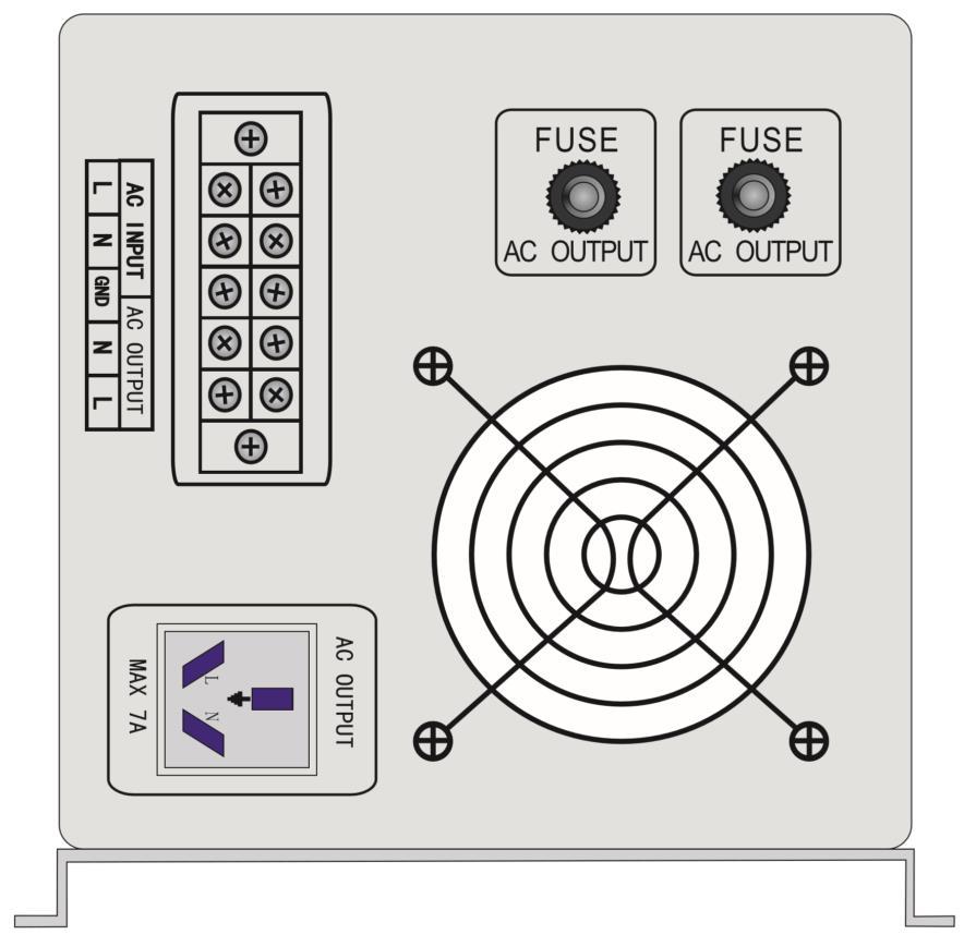

7 7
8 2.5 Electrical Performance Invert Topology The inverter/charger is built according to the following topology. Invert: Full Bridge Topology. Charge: Isolated Boost Topology. It works bi-directionally: in one direction it converts DC power from the battery to AC power (Inverter Mode) and in the other direction it converts external AC power to DC power to charge the batteries (AC Mode). The same power components are used in both directions, resulting in high-energy transfer efficiency with fewer components. Please note that the inverter/charger can only work in one direction at one time (i.e. it can not work as an inverter and as a charger at the same time). When operating in invert mode, the direct current (DC) that enters the inverter from the batteries is filtered by a large input capacitor and switched On and Off by the Metal Oxide Silicon Field Effect Transistors (MOSFET) at a rate of 50 Hz or 60Hz, in this step the DC is converted to low voltage synthesized sine wave AC using an H-bridge configuration and high frequency PWM (Pulse Width Modulation) technique. It is then directed into the transformer which steps the low AC voltage up to 230 or 120 volts. The unit has a 16bit, 4.9MHZ microprocessor to control the output voltage and frequency as the DC input voltage and/or output load varies. Because of high efficiency MOSFETs and the heavy transformers, it outputs PURE SINE WAVE AC with low THD. The peak efficiency of Sigineer Power inverter is 88%. Don t parallel the AC output of the inverters to increase power capacity as they have no stacking functionality. Overload Capacity The Sigineer Power APC Series inverters have different overload capacities, making it ideal to handle demanding loads. 1 For 110%<Load<120%(±10%), beeps 0.5s every 1s, and Fault(Turn off) after 30 seconds. 2 For 160%<Load, Fault(Turn off) after 300ms. Soft Start in Inverter Mode The inverter is engineered with Soft Start feature. When the inverter is turned on, the output voltage gradually ramps up from 0VAC to rated voltage in about 1.2 sec. This effectively reduces otherwise very high starting inrush current drawn by AC loads such as Switched Mode Power Supplies and inductive loads. This will result in lower motor inrush current, which means less impact on the loads and inverter. Caution: 8
9 After the inverter is switched on, it takes a finite time for it to self diagnose and get ready to deliver full power. Hence, always switch on the load(s) after a few seconds of switching on the inverter. Avoid switching on the inverter with the load already switched on. This may prematurely trigger the overload protection. When a load is switched on, it may require initial higher power surge to start. Hence, if multiple loads are being powered, they should be switched on one by one so that the inverter is not overloaded by the higher starting surge if all the loads are switched on at once AC Charger Sigineer Power inverter is equipped with an active PFC (Power Factor Corrected) multistage battery charger. The PFC feature is used to control the amount of power used to charge the batteries in order to obtain a power factor as close as possible to 1. Unlike other inverters whose max charging current decreases according to the input AC voltage, Sigineer Power APC Series charger is able to output max current as long as input AC voltage is in the range of Vac, and AC freq is in the range of 48-54Hz(58-64Hz for 60Hz model). There are 3 main stages: Bulk Charging: This is the initial stage of charging. While Bulk Charging, the charger supplies the battery with controlled constant current. The charger will remain in Bulk charge until the Absorption charge voltage (determined by the Battery Type selection) is achieved. Software timer will measure the time from A/C start until the battery charger reaches 0.3V below the boost voltage, then take this time ast0 and T0 10 = T1. Absorb Charging: This is the second charging stage and begins after the absorb voltage has been reached. Absorb Charging provides the batteries with a constant voltage and reduces the DC charging current in order to maintain the absorb voltage setting. In this period, the inverter will start a T1 timer; the charger will keep the boost voltage in Boost CV mode until the T1 timer has run out. Then drop the voltage down to the float voltage. The timer has a minimum time of 1 hour and a maximum time of 12 hours. Float Charging: The third charging stage occurs at the end of the Absorb Charging time. While Float charging, the charge voltage is reduced to the float charge voltage (determined by the Battery Type selection*). In this stage, the batteries are kept fully charged and ready if needed by the inverter. If the A/C is reconnected or the battery voltage drops below 12Vdc/24Vdc/48Vdc, the charger will reset the cycle above. If the charge maintains the float state for 10 days, the charger will deliberately reset the cycle to protect the battery. 9
10 Battery type selector Switch setting Description Boost / Vdc Float / Vdc 0 Charger Off 1 Gel USA AGM AGM 2 / Lithium Battery Sealed lead acid Gel EURO Open lead acid Calcium De sulphation 15.5 (4 Hours then Off) 9 Not used (*12 for 144Vdc ; ) Use with Lithium Ion Battery Packs Lithium-ion refers to a variety of lithium-based battery chemistries. The most popular is the large-format prismatic lithium iron phosphate (LiFePO4; LFP) battery. Our smart battery charger works with various lithium batteries, pls check the battery specs and make sure our charging algorithm suits their charge voltage and cut off voltages. If our current charging algorithms don t match your lithium battery, welcome to contact us at for a customization. De-sulphation The de-sulphation cycle on switch position 8 is marked in red because this is a very dangerous setting if you 10
11 do not know what you are doing. Before ever attempting to use this cycle you must clearly understand what it does and when and how you would use it. What causes sulphation? This can occur with infrequent use of the batteries, nor if the batteries have been left discharged so low that they will not accept a charge. This cycle is a very high voltage charge cycle designed to try to break down the sulphated crust that is preventing the plates from taking a charge and thus allow the plates to clean up and accept a charge once again. The charging capacity will go to peak charge rate in about 3 seconds. This may cause a generator to drop frequency, making the inverter transfer to battery mode. It is suggested to gradually put the charging load on the generator by switching the charging switch from min to max. Together with the 15s switch delay our inverter gives the generator enough time to spin up. This will depend on the size of the generator and rate of charge. As a general Rule, the Bulk Charging Current should be limited to 30% of the capacity of the battery bank. Higher charging current may be used if permitted by the battery manufacturer. Changing max charging current. Caution: To guarantee the best performance of AC charger when the AC input is from a generator, the standby generator should be of at least 150% higher capacity than the inverter. Warning! Operation with an under-rated generator or generator with unqualified wave form may cause premature failure which is not under warranty Transfer Swift Power Transfer While in the Standby Mode, the AC input of the inverter is continually monitored. Whenever AC power falls below the low AC voltage trip voltage (154 Vac, default setting for 230VAC,90VAC for 120VAC), the inverter automatically transfers back to the Invert Mode with minimum power interruption to your appliances - as long as the inverter is turned on. The transfer from Standby mode to Inverter mode occurs in approximately 10 milliseconds. And it is even shorter from Inverter mode to Standby mode. This transfer time is usually fast enough to keep your equipment (including computers) powered up, thus our inverter can be used as a line interactive UPS. Synchronized Power Transfer When a load is transferred from inverter AC output to another backup AC source of power through a transfer switch, there will be a finite interruption of power to the load for the transfer to take place. A mismatch of phase and frequency of the inverter AC output and the backup AC source in transfer is likely to damage the backup AC source / a reactive load. With sophisticated circuitry design, our inverter will first lock on the frequency and phase of the input shore power/generator power and make a smooth and safe transfer at the zero voltage point to minimize the impact on the power modules. Transfer Delay There is a 15-second delay from the time the inverter senses that continuously qualified AC is present at the input terminals to when the transfer is made. This delay is built in to provide sufficient time for a generator 11

.")
 detected, the inverter automatically goes back into search mode to minimize energy consumption from the battery bank.")
12 to spin-up to a stable voltage and frequency and avoid relay chattering. The inverter will not transfer to generator until it has locked onto the generator s output. This delay is also designed to avoid frequent switching when input utility is unstable Power Saver There are 2 different working statuses for APC inverter: Power On and Power Off. When power switch is in Unit Off position, the inverter is powered off. When power switch is turned to either of Power Saver Auto or Power Saver Off, the inverter is powered on. Power saver function is to dedicated to conserve battery power when AC power is not or little required by the loads. In this mode, the inverter pulses the AC output looking for an AC load (i.e., electrical appliance). Whenever an AC load (greater than 25 watts) is turned on, the inverter recognizes the need for power and automatically starts inverting and output goes to full voltage. When there is no load (or less than 25 watts) detected, the inverter automatically goes back into search mode to minimize energy consumption from the battery bank. In Power saver on mode, the inverter will draw power mainly in sensing moments, thus the idle consumption is significantly reduced. The inverter is factory defaulted to detect load for 250ms in every 30 seconds. This cycle can be customized to 3 seconds thru the SW3 on DIP switch. Power saver on Power saver off Power saver on (Load detected) Figure 8 Figure 9 Figure 10 Note: The minimum power of a load to take inverter out of sleep mode (Power Saver On) is 50 Watts. For split phase models, the power threshold of sleep mode is 50W between Hot1 and Neutral and 200W between Hot 1 and Hot 2. There is no load detection between Hot2 and Neutral. Note: The minimum power of a load to take inverter out of sleep mode (Power Saver On) is 25 Watts. The Sigineer Power APC Series is designed with extraordinarily low idle power consumption which is only a mere % of its rated power. When in the search sense mode, the green power LED will blink and the inverter will make a ticking sound. At full output voltage, the green power LED will light steadily and the inverter will make a steady humming sound. When the inverter is used as an uninterruptible power supply the search sense mode function should be defeated. Exceptions Some devices when scanned by the load sensor cannot be detected. Small fluorescent lights are the most common example. (Try altering the plug polarity by turning the plug over.) Some computers and sophisticated electronics have power supplies that do not present a load until line voltage is available. When 12

13 this occurs, each unit waits for the other to begin. To drive these loads either a small companion load must be used to bring the inverter out of its search mode, or the inverter may be programmed to remain at full output voltage Protections The Sigineer Power APC Series inverter is equipped with extensive protections against various harsh situations/faults. These protections include: AC Input over voltage protection/ac Input low voltage protection Low battery alarm/high battery alarm Over temperature protection/over load protection Short Circuit protection (1s after fault) Back feeding protection When Over temperature /Over load occur, after the fault is cleared, the master switch has to be reset to restart the inverter. The Low battery voltage trip point can be customized from defaulted value of 10VDC to 10.5VDC through the SW1 on the DIP switch. The inverter will go to Over temp protection when the heat sink temp. 105ºC (221 ), and will go to Fault (shutdown Output) after 30 seconds. The switch has to be reset to activate the inverter. The Sigineer Power APC Series Inverter is with back feeding protection which avoids presenting an AC voltage on the AC input terminal in Invert mode. After the reason for fault is cleared, the inverter has to be reset to start working LED Indicator & LCD The operation status of the inverter is shown by the LED s and the explanation on the LED sticker. 13
14 ON/OFF button:press for 5 secs to turn on or turn off the inverter. Mute,mute off,01general mode,02power saving mode 03Battery mode. Use 03 to transfer after starting. Operation method: 1 :Press for 1 sec, screaming 1 time, mute on. There is not audile alarm. 2 :Press for 1 sec again, screaming 2 times, mute off. 3 :Press for 5 sec, choose 01,02,03 in cycling, corresponding data displayed on LCD INPUT. The selected mode can be functional when the inverter is restarted. Charging current 0-30A setting,up button (up). 1 :Press for 5 sec,corresponding C+. displayed on LCD INPUT side. 2:When it is displayed, press up to add current, press down to cut current, C0-C6. 3:CO=0A,C1=5A,C2=10A,C3=15A,C4=20A, C5=25A,C6=30A. Battery type setting, Down(down). 1 :Press for 5 sec, corresponding U+ displayed on LCD INPUT. 2 :When display, press Up or Down to choose battery type.u0-u Audible Alarm The inverter also gives audible alarms when the following situations occur. Battery Voltage Low Inverter green LED Lighting, and the buzzer beep 0.5s every 5s. Inverter green LED Lighting, and the buzzer beep 0.5s every 1s, Battery Voltage High and Fault after 60s. (1)110%<load<125%(±10%), No audible alarm in 14 minutes, Beeps 0.5s every 1s in 15 th minute and Fault after 15 minutes; Invert Mode Over-Load (2)125% <load<150%(±10%), Beeps 0.5s every 1s and Fault after 60s; (3)Load>150%(±10%), Beeps 0.5s every 1s and Fault after 20s; Heat sink temp. 105ºC(221 ), Over temp red LED Lighting, beeps 0.5s Over Temperature every 1s; 14
15 2.5.9 FAN Operation For 1-3KW, there is one multiple controlled DC fan which starts to work according to the following logics. For 4-6KW, there is one multiple controlled DC fan and one AC fan. The DC fan will work in the same way as the one on 1-3KW, while the AC fan will work once there is AC output from the inverter. So when the inverter is in power saver mode, the AC fan will work from time to time in response to the pulse sent by the inverter in power saver mode. The Operation of DC fan at the DC terminal side is controlled in the following logic: Condition Enter Condition Leave condition Speed HEAT SINK T < 85 (185 ) T 85 (185 ) 50% TEMPERATURE T 85 (185 ) T < 80 (176 ) 100% CHARGER I 50%Max I > 50%Max 50% CURRENT I > 50%Max I 40%Max 100% LOAD Percentage Load < 50% Load 50% 50% (INV MODE) Load 50% Load 40% 100% Allow at least 30CM of clearance around the inverter for air flow. Make sure that the air can circulate freely around the unit. Fan noise level <60db at a distance of 1m 3.1 Unpacking and Inspection 3 Installation Carefully remove the inverter/charger from its shipping package and inspect all contents. Verify the following items are included: The Inverter/Charger Red and black DC terminal covers AC terminal block cover with two Phillips screws Two Flange nuts and 4 M8 Phillips screws (installed on the DC terminals). One Owner s Manual If items appear to be missing or damaged, contact our authorized dealer or us. If at all possible, keep your shipping box. It will help protect your inverter from damage if it ever needs to be returned for service. Save your proof-of-purchase as a record of your ownership; it will also be needed if the unit should require warranty work. 3.2 Installation Location 15
16 Follow all the local regulations to install the inverter. Please install the equipment in an INDOOR location of Dry, Clean, Cool with good ventilation. Working temperature: -10 to 40 (-14 to 104 ) Storage temperature: -40 to 70 (-40 to 158 ) Relative Humidity: 0% to 95%,non-condensing Cooling: Forced air CAUTION: Some models of the inverters are heavy. Use proper lifting techniques during installation to prevent personal injury. WARNING! The inverter should not be installed in an area that allows dust, fumes, insects or rodents to enter or block the inverter s ventilation openings. This area also must be free from any risk of condensation, water or any other liquid that can enter or fall on the inverter. The entire line of inverters has been processed with a conformal coating on the PCB, making it water, rust, and dust resistant. While these units are designed to withstand corrosion from the salty air, they are not splash proof. The inverter s life is uncertain if used in these types of environments, and inverter failures under these conditions are not covered under warranty. 3.3 DC Wiring It is suggested the battery bank be kept as close as possible to the inverter. The following is a suggested wiring option for 3 meter DC cable. Please find the following minimum wire size. In case of DC cable longer than 3m, please increase the cross section of cable to reduce the loss. Please follow the above minimum wire size requirement. One cable is always best, but if there is a problem obtaining the recommended size or larger cable, multiple smaller cables will work. Performance of any product can be improved by thicker cable and shorter runs, so if in doubt round up and keep the length as short as possible. Battery cables must have crimped (or preferably, soldered and crimped) copper compression lugs unless aluminum mechanical lugs are used. Soldered connections alone are not acceptable. High quality, UL-listed battery cables are available.these cables are color-coded with pressure crimped, sealed ring terminals. Battery terminal must be clean to reduce the resistance between the DC terminal and cable connection. A buildup of dirt or oxidation may eventually lead to the cable terminal overheating during periods of high current draw. Use a stiff wire brush and remove all dirt and corrosion from the battery terminals and cables. Power DC Input Wire Gage voltage 1KW 12V AWG 4 1KW 24V AWG 6 1.5KW 12V AWG 1/0 1.5KW 24V AWG 4 2KW 12V AWG 1/0 2KW 24V AWG 1/0 2KW 48V AWG 6 3KW 12V AWG 4/0 3KW 24V AWG 1/0 3KW 48V AWG 4 4KW 24V AWG 1/0 4KW 48V AWG 1/0 5KW 24V AWG 4/0 5KW 48V AWG 1/0 6KW 24V AWG 4/0 6KW 48V AWG 1/0 16

17 Reducing RF interference To reduce the effect of radiated interference, twist the DC cables. To further reduce RF interference, shield the cables with sheathing /copper foil / braiding. Taping battery cables together to reduce inductance Do not keep the battery cables far apart. In case it is not convenient to twist the cables, keep them taped together to reduce their inductance. Reduced inductance of the battery cables helps to reduce induced voltages. This reduces ripple in the battery cables and improves performance and efficiency. WARNING The torque rating range for DC terminal is 12.5NM-20.5NM ( pound-foot), and the suggested torque rating is 17NM (12.6 pound-foot). Over torquing may break the bolt. Equipment Damage The inverter is not reverse polarity protected. Reversing the battery polarity on the DC input connections will cause permanent damage to the inverter which is not covered under warranty. Always check polarity before making connections to the inverter. The inverter contains capacitors that may produce a spark when first connected to battery. Do not mount in a confined compartment with vented battery or gases. Ensure the inverter is off before disconnecting the battery cables, and that AC power is disconnected from the inverter input. 3.4 AC Wiring We recommend using 10 to 5Awg wire to connect to the ac terminal block. When in AC mode the AC input power will supply both the loads and AC charger, a thicker wire gauge for AC Input is required. Pls consult a qualified electrician about the specific wire gauge required in terms of wire material and inverter power. There are 3 different ways of connecting to the terminal block depending on the model. All the wirings are CE compliant, Call our tech support if you are not sure about how to wire any part of your inverter. 17


18 Wiring Option 1 230V single phase/120v single phase Input: Ground+Hot line+neutral Output: Neutral+ Hot line+ground Wiring Option 2 120/240V split phase Input: Ground + Hot line+ Hot line Output: Hot line+ Hot line +Neutral Wiring Option 3 120/240V split phase Input: Ground + Hot line+ Hot line Output: Hot line +Neutral Remark: In such case, each 120Vac output hotline can only carry a max of half the rated capacity. Caution: Wiring Option 2 and Wiring Option 3 are only allowed for 110/220V split phase models. Pls wire all the other models according to Wiring Option 1. WARNING For split phase models, AC input neutral is not required in wiring. Never Connect Input Neutral to Ground or to Output Neutral. Damage will result which is not covered under warranty. The output voltage of this unit must never be connected in its input AC terminal, 18
19 overload or damage may result. Always switch on the inverter before plugging in any appliance. Damages caused by AC wiring mistakes are not covered under warranty. Preventing Paralleling of the AC Output The AC output of the unit should never be connected to the utility power / generator. Such a connection may result in parallel operation of the different power sources and AC power from the utility / generator will be fed back into the unit which will instantly damage the inverter and may also pose a fire and safety hazard. 3.5 Grounding Connect an AWG 8 gauge or greater copper wire between the grounding terminal on the inverter and the earth grounding system or the vehicle chassis. 3.6 Mounting the Inverter In order to mount the inverter securely, the surface and the mounting hardware must also be able to support at least twice the weight of the inverter. To meet regulatory safety requirements, the Sigineer Power APC Series must be mounted: 1: On a horizontal surface (shelf or table top) with top side up, 2: On a vertical surface (like a wall) with the DC terminals facing left and the fan axis horizontal. 3: On a vertical surface (like a wall) with the DC terminals facing down and the fan axis vertical. Warning! Don t mount the inverter upside down. The inverter surface may get as high as 80 (176 ) during operation, do not touch. The unit should be installed so it is not likely to come into contact with people. After determining the mounting position, refer to the physical dimensions as shown in below figures or use the base of the inverter as a template to mark your mounting screw locations. After marking the mounting screw locations, mount the unit with appropriate mounting hardware. Symptom Possible Cause Recommended Solution Inverter will not turn on during Batteries are not connected, loose Check the batteries and cable initial power up. battery-side connections. Low battery voltage. connections. Check DC fuse and breaker. Charge the battery. No AC output voltage and no indicator lights ON. Inverter has been manually transitioned to OFF mode. Press the switch to Power saver on or Power saver off position. AC output voltage is low and the inverter turns loads OFF in a short time. Charger is inoperative and unit will not accept AC. Low battery. AC voltage has dropped out-of-tolerance 19 Check the condition of the batteries and recharge if possible. Check the AC voltage for proper voltage and frequency.
20 Charger is supplying a lower charge rate. Charger controls are improperly set. Low AC input voltage. Refer to the section on adjusting the Charger Rate. Source qualified AC power. Charger turns OFF while charging from a generator. Sensitive loads turn off temporarily when transferring between grid and inverting. Noise from Transformer/case* Loose battery or AC input connections. High AC input voltages from the generator. Inverter's Low voltage trip voltage may be too low to sustain certain loads. Applying specific loads such as hair drier Check all DC /AC connections. Load the generator down with a heavy load. Turn the generator output voltage down. Choose narrow AC voltage in the DIP switch, or Install a UPS if possible. Remove the loads *The reason for the noise from transformer and/or case When in inverter mode and the transformer and/or case of the inverter sometimes may vibrate and make noise. If the noise comes from transformer. According to the characteristics of our inverter, there is one type of load which will most likely to cause rattles of transformer. That is a half-wave load, load that uses only a half cycle of the power(see figure 1). This trends to cause imbalance of magnetic field of transformer, reducing its rated working freq from 20KHz to, say, maybe 15KHz (it varies according to different loads). This way, the freq of noise falls exactly into the range (200Hz-20KHz) that human ear can sense. The most common load of such kind is hair drier. If the noise comes from case. Normally when loaded with inductive loads, the magnetic field generated by transformer keeps attracting or releasing the steel case at a specific freq, this may also cause noise. Reducing the load power or using an inverter with bigger capacity will normally solve this problem. The noise willn t do any harm to the inverter or the loads. 5 Warranty We warrant this product against defects in materials and workmanship for a period of one year from the date of purchase and will repair or replace any defective APC Inverter when directly returned, postage prepaid, to 20
21 manufacturer. This warranty will be considered void if the unit has suffered any obvious physical damage or alteration either internally or externally and does not cover damage arising from improper use such as plugging the unit into an unsuitable power sources, attempting to operate products with excessive power consumption requirements, reverse polarity, or use in unsuitable climates. WARRANTY DOES NOT INCLUDE LABOR, TRAVEL CHARGES, OR ANY OTHER COSTS INCURRED FOR REPAIR, REMOVAL, INSTALLATION, SERVICING, DIAGNOSING OR HANDLING OF EITHER DEFECTIVE PARTS OR REPLACEMENT PARTS. THE WARRANTOR ASSUMES NO LIABILITY FOR INCIDENTAL OR CONSEQUENTIAL DAMAGES OF ANY KIND. LOSS OR DAMAGE: Loss or damage in transit is the responsibility of the carrier. Any claim should be filed with the delivering transport company. Invoice, Bill of Lading and Delivery receipt with damage noted therein must accompany any claims for freight damage. Claims for shortage and lost shipments must be made in writing to the shipper within 3 days of the receipt of shipment. Claims not reported within this time frame will not be honored. This warranty does not apply to and we will not be responsible for any defect in or damage to: a) the product if it has been misused, neglected, improperly installed, physically damaged or altered, either internally or externally, or damaged from improper use or use in an unsuitable environment; violations of the warnings in the manual will invalid the warranty. b) the product if it has been subjected to fire, water, generalized corrosion, biological infestations, or input voltage that creates operating conditions beyond the maximum or minimum limits listed in the product specifications including high input voltage from generators and lightning strikes; c) the product if repairs have been done to it other than by our company or its authorized service centers; Appendix 1 Sigineer Power Inverter & Charger Electrical Specifications Model 1KW 1.5KW 2KW 3KW 4KW 5KW 6KW Continuous Output Power 1000W 1500W 2000W 3000W 4000W 5000W 6000W Surge Rating(20s) 3000W 4500W 6000W 9000W 12000W 15000W 18000W Capable of Starting Electric Motor 1HP 1.5HP 2HP 3HP 4HP 5HP 6HP Output Waveform Pure Sine wave/same as input(bypass mode) Peak Efficiency 88% Line Mode Efficiency >95% Inverter Output Power Factor Nominal Output Voltage rms Vac / Vac Output Voltage Regulation ±10% RMS Output Frequency 50/60Hz ± 0.3Hz Short Circuit Protection Yes, Current Limit Function (Fault after 1sec) Typical transfer Time 10ms(Max) THD < 10% Nominal Input Voltage 12.0Vdc ( *2 for 24Vdc, *4 for 48Vdc) DC Input Minimum Start Voltage 10.0Vdc Low Battery Alarm 10.5Vdc / 11.0Vdc 21
22 Charge Bypass & Protection Mechanical Specification Low Battery Trip 10.0Vdc / 10.5Vdc High Voltage Alarm & Fault 16.0Vdc High DC Input Recovery 15.5Vdc Low Battery voltage recover 13.0Vdc Sleep Mode Threshold > 25 W when Power Saver On Narrow: 100~135VAC / 194~243VAC; Input Voltage Range Wide: 90~135VAC / 164~243VAC; Narrow: 47-55±0.3Hz for 50Hz, 57-65±0.3Hz for 60Hz Input Frequency Range Wide:43±0.3Hz plus for 50Hz/60Hz Output Voltage Depends on battery type Charger Breaker Rating(230Vac) 10A 10A 10A 20A 20A 30A 30A Charger Breaker Rating(120Vac) 10A 20A 20A 30A 40A N/A N/A Max Charge Rate See specific charge rates in AC Charger section Over Charge Protection Shutdown 15.7V for 12Vdc ( *2 for 24Vdc, *4 for 48Vdc) Battery type Fast Vdc Float Vdc Gel U.S.A A.G.M A.G.M Sealed Lead Acid Gel Euro Open Lead Acid Calcium De-sulphation 15.5 for 4hrs Remote Control Yes. Optional Input Voltage Waveform Sine wave (Grid or Generator) Nominal Voltage 120Vac 230Vac Low Voltage Trip 80V/90V±4% 184V/154V±4% Low Voltage re engage 90V/100V±4% 194V/164V±4% High Voltage Trip 140V±4% 253V±4% High Voltage re engage 135V±4% 243V±4% Max Input AC Voltage 150VAC 270VAC Nominal Input Frequency 50Hz or 60Hz (Auto detect) Narrow: 47±0.3Hz for 50Hz, 57±0.3Hz for 60Hz Low Freq Trip Wide:40±0.3Hz for 50Hz/60Hz Narrow: 48±0.3Hz for 50Hz, 58±0.3Hz for 60Hz Low Freq re engage Wide:45±0.3Hz for 50Hz/60Hz Narrow: 55±0.3Hz for 50Hz, 65±0.3Hz for 60Hz High Freq Trip Wide: No up limit for 50Hz/60Hz Narrow: 54±0.3Hz for 50Hz, 64±0.3Hz for 60Hz High Freq re engage Wide: No up limit for 50Hz/60Hz Output Short circuit protection Circuit breaker Bypass breaker rating (230Vac) 10A 15A 20A 30A 30A 40A 40A Bypass breaker rating (120Vac) 20A 20A 30A 40A 50A N/A N/A Mounting Wall/Ground mount Inverter Dimensions(L*W*H) 442*218*179mm 442*218*179mm 598*218*179mm 17.5*8.5*7 17.5*8.5*7 23.5*8.5*7 Inverter Weight 16KG 17KG 20KG 24KG 35KG 44KG 45KG 22
23 Shipping Dimensions(L*W*H) Shipping Weight Display Standard Warranty 35.27lbs lbs 44.1 lbs lbs lbs 97 lbs lbs 595*330*320mm 595*330*320mm 800*360*350mm 23.5*13* *13* *14.25* KG 19KG 22KG 26KG 37KG 46KG 47KG lbs lbs lbs lbs lbs lbs lbs Status LEDs 1 Year Specifications in this manual are subject to change without prior notice. 23
24 Shenzhen Sigineer Power CO.,LTD. TEL: FAX: Add: Bld A, Jiali Industrial Zone, Yuanfen Rd, Longhua, Shenzhen, , China SAVE THIS MANUAL! READ THIS MANUAL BEFORE INSTALLATION, IT CONTAINS IMPORTANT SAFETY, INSTALLATION AND OPERATING INSTRUCTIONS. KEEP IT IN A SAFE PLACE FOR FUTURE REFERENCE. WE WISH YOU A PLEASANT EXPERIENCE IN USING OUR INVERTERS. 24
CS+ Series. Pure Sine Wave Inverter/Charger User s Manual. Version 1.0 DIF
 CS+ Series Pure Sine Wave Inverter/Charger User s Manual Version 1.0 DIF The CS+DIF range of Inverter /Chargers are powerful, robust and professional. It includes in one unit three functions : a powerful
Global LF Series Pure Sine Wave Inverter Charger User s Manual PICOGLF12W12V120AL & PICOGLF25W12V120AL
 Global LF Series Pure Sine Wave Inverter Charger User s Manual PICOGLF12W12V120AL & PICOGLF25W12V120AL Table of Contents... - 1-1. Important Safety Information... - 2-1-1. General Safety Precautions...
SP Series 600W&1,000W Pure Sine Wave Inverter/Charger User s Manual. For Models SP SP SP SP
 SP Series 600W&1,000W Pure Sine Wave Inverter/Charger User s Manual For Models SP0612120 SP0612230 SP1012120 SP1012230 1 Table of Contents 1 Important Safety Information... 3 1.1 General Safety Precautions...
Global LF Series Pure Sine Wave Inverter/AC Charger User s Manual. Version 7.0
 Global LF Series Pure Sine Wave Inverter/AC Charger User s Manual Version 7.0 Table of Contents 1. Important Safety Information... - 2-1-1. General Safety Precautions... - 2-1-2. Precautions When Working
AP Series Pure Sine Wave Inverter/Charger User s Manual. Version 1.0
 AP Series Pure Sine Wave Inverter/Charger User s Manual Version 1.0 Composer: Franklin Chu Date: Feb 12 th, 2012 1 Table of Contents 1. Important Safety Information... 3 1-1. General Safety Precautions...
TXF Series. Pure Sine Wave Inverter/AC Charger User s Manual. Version 1.0. TorTech. Designed to ISO9001 manufacturing standard
 TXF Series Pure Sine Wave Inverter/AC Charger User s Manual Version 1.0 TorTech Designed to ISO9001 manufacturing standard Total Transformer Solutions Australia s Transformer Specialist for 25 Years Tel:
APS & APS
 POWER INVERTER APS1000-12 & APS2000-24 Table of Contents Important Safety Information...................... 1 General Safety Precautions...................... 1 Precautions When Working With Batteries..............
PureWatts Elite Power Inverter. Instruction Manual 1000 / 2000 WATTS
 PureWatts Elite Power Inverter Instruction Manual 1000 / 2000 WATTS www.sinergex.com 1 CONTENTS Introduction 3 Important Safety Information 3 Features & Applications 4 Electrical Performance 5 Mechanical
DP Series Pure Sine Wave Inverter/Charger User s Manual
 DP Series Pure Sine Wave Inverter/Charger User s Manual Table of Contents 1. Important Safety Information...3 1.1 General Safety Precautions...3 1.2 Precautions When Working with Batteries...3 2. Introduction...4
User Manual & Installation Instructions
 12KW Inverter Charger Residential & Commercial User Manual & Installation Instructions Model SEI 12 Off Grid + On Grid + AC Charger + MPPT + AGS +ATS + UPS 1-1. General Safety Precautions 1. Before installing
UL458 Listed 1.5KW 2KW 3KW Pure Sine Wave Inverter/Charger User s Manual
 UL458 Listed 1.5KW 2KW 3KW Pure Sine Wave Inverter/Charger User s Manual Shenzhen Sigineer Power CO.,LTD. Email: TEL: +86 755 2160 7078 FAX: +86 755 6165 8278 Add: Bld A, Jiali Industrial Zone, Yuanfen
Global LF Series Pure Sine Wave Inverter/ Charger User s Manual
 Global LF Series Pure Sine Wave Inverter/ Charger User s Manual For PICOGLF6W12V120VR 1 Table of Contents 1.1 General Safety Precautions... 3 1.2 Precautions When Working with Batteries... 3 2.1 General
Global LF Series Pure Sine Wave Inverter Charger User s Manual. Version 2.0 PICOGLF10KW48V240VS
 Global LF Series Pure Sine Wave Inverter Charger User s Manual Version 2.0 PICOGLF10KW48V240VS Table of Contents 1. Important Safety Information... - 3-1.1 General Safety Precautions... - 3-1.2 Precautions
S150,S300 Series Pure Sine Wave Inverter User s Manual
 S150,S300 Series Pure Sine Wave Inverter User s Manual List of contents 1. Important Safety Instructions 3 1-1 General Safety Precautions 3 1-2 Precautions When Working With Batteries.. 3 2. Features...
MINI/ PSW7 Series. Pure Sine Wave Inverter/Charger User s Manual. Version 1.0. Your Best Partner for Power
 MINI/ PSW7 Series Pure Sine Wave Inverter/Charger User s Manual Version 1.0 Contact information email: sales@foxpowerups.com Website: www.foxpowerups.com Table of Contents 1. Important Safety Information
Global LF Series Pure Sine Wave Inverter/ Chargers 5-12KW User s Manual. Version 4.0 (Code: / Updated on NOV 14 th 2013)
") Global LF Series Pure Sine Wave Inverter/ Chargers 5-12KW User s Manual Version 4.0 (Code: 614-01208-00 / Updated on NOV 14 th 2013) 1 Table of Contents 1. Important Safety Information... 3 1-1. General
Global LF Series Pure Sine Wave Inverter/ Chargers 5-12KW User s Manual Version 4.0 (Code: 614-01208-00 / Updated on NOV 14 th 2013) 1 Table of Contents 1. Important Safety Information... 3 1-1. General
S600,S600R Series Pure Sine Wave Inverter User s Manual
 S600,S600R Series Pure Sine Wave Inverter User s Manual List of contents 1. Important Safety Instructions 1 1-1 General Safety Precautions 1 1-2 Precautions When Working With Batteries.. 1 2. Features...
1KW to 6KW Pure Sine Wave Inverter/Charger User s Manual
 1KW to 6KW Pure Sine Wave Inverter/Charger User s Manual Enfoque Solar TEL:(664)3443322 CEL(045)(664)1275948/ VIA RAPIDA ORIENTE No. 14750 Bodega 829 830 GUADALUPE VICTORIA CP. 22426 TIJUANA BAJA CALIFORNIA,
MINI/ PSW7 Series. Pure Sine Wave Inverter/Charger User s Manual. Version 1.0
 MINI/ PS7 Series Pure Sine ave Inverter/Charger User s Manual Version 1.0 Table of Contents 1. Important Safety Information... - 2-1.1 General Safety Precautions... - 2-1.2 Precautions hen orking with
Global LF Series Pure Sine Wave Inverter Charger User s Manual
 Global LF Series Pure Sine Wave Inverter Charger User s Manual Version 2.0 PICOGLF4KW & 6KW ETL Certified to UL 1741 & CSA STDC 22.2 NO. 107.1 Table of Contents 1. Important Safety Information... - 3-1.1
SA-1000K & SA-3000K Series Pure Sine Wave Inverter User s Manual
 SA-1000K & SA-3000K Series Pure Sine Wave Inverter User s Manual Table of Contents 1. Important Safety Information. 1 1-1 General Safety Precautions 1 1-2 Battery Precautions.... 1 2. Features... 2 2-1
Spartan Power Pure Sine Wave Inverter/Charger User Manual. Version 1.0
 Spartan Power Pure Sine Wave Inverter/Charger User Manual Version 1.0 Table of Contents 1. Important Safety Information... - 2-1-1. General Safety Precautions... - 2-1-2. Precautions When Working with
Pure Sine Wave Inverter/Charger
 Pure Sine Wave Inverter/Charger User s Manual(up to 15KW) Version 5.2 (PN:50000-2018168) Shenzhen Sigineer Power CO.,LTD. Email: info@sigineer.com TEL: +86 755 2160 7078 FAX: +86 755 6165 8278 Add: Bld
Don't let the shadows of yesterday hide the sunshine of tomorrow Nandina Morris
 Don't let the shadows of yesterday hide the sunshine of tomorrow. -------------- Nandina Morris Hybrid MPPT Solar Inverter Main Features Pure sine wave inverter Built-in MPPT solar charge controller Selectable
PureSine 150/300 Pure Sine Wave Inverter User s Manual
 PureSine 150/300 Pure Sine Wave Inverter User s Manual 1. Important Safety Instructions WARNING! Before you install and use your Inverter, please read and follow these safety instructions. 1-1. General
Go Power! Manual. GP-Smart Charger
 Go Power! Manual GP-Smart Charger Go Power! Electric Inc. PO Box 6033 Victoria, BC V8P 5L4 Toll Free Tel: 866-247-6527 Toll Free Fax: 866-607-6527 Email: info@gpelectric.com Table of Contents 1. IMPORTANT
AP/APP/APS/APV Series
 AP/APP/APS/APV Series Pure Sine Wave Inverter/Charger User s Manual Version 1.0-1 - Table of Contents 1. Important Safety Information... 3 1-1. General Safety Precautions... 3 1-2. Precautions When Working
GP-1000 Inverter. Go Power! Electric Inc. PO Box 6033 Victoria, BC V8P 5L4 Tel: Fax:
 Go Power! Manual GP-1000 Inverter Go Power! Electric Inc. PO Box 6033 Victoria, BC V8P 5L4 Tel: 866-247-6527 Fax: 866-607-6527 Email: info@gpelectric.com Table of Contents 1. INTRODUCTION 3 2. SPECIFICATIONS
DC AC POWER INVERTER. LIV 10 / LIV 20 / LIV 30 User Manual
 DC AC POWER INVERTER LIV 10 / LIV 20 / LIV 30 User Manual Save This Manual Please read this manual carefully prior to storage, installation, wiring, operation and maintenance of the Power Inverter. This
Pure Sine Wave DC TO AC Power Inverter. User s Manual
 Pure Sine Wave DC TO AC Power Inverter User s Manual Distributed by: Tech Brands by Electus Distribution 320 Victoria Road, Rydalmere NSW Australia Tel: 1300 738 555 Fax: 1300 738 500 www.techbrands.com
S600,S600R Series Pure Sine Wave Inverter User s Manual
 S600,S600R Series Pure Sine Wave Inverter User s Manual Table of contents 1. Important Safety Information. 1 1-1 General Safety Precautions 1 1-2 Batteries Precautions.. 1 2. Features... 2 2-1 Applications..
GSL Electronics Modified Sine Wave Power Inverters
 GSL Electronics Modified Sine Wave Power Inverters Congratulations on choosing one of our Modified Sine Wave Inverters for your application. There are 6 models in the range, which will meet most of your
Go Power! Manual. GP-1750HD Inverter GP-2500 Inverter
 Go Power! Manual GP-1750HD Inverter GP-2500 Inverter Go Power! Electric Inc. PO Box 6033 Victoria, BC V8P 5L4 Tel: 866-247-6527 Fax: 866-607-6527 Email: info@gpelectric.com Table of Contents 1. INTRODUCTION...
Global LF Series Pure Sine Wave Inverter Charger User s Manual
 Global LF Series Pure Sine Wave Inverter Charger User s Manual PICOGLF6W12V120V ETL Listed to UL 458 and CSA 22.2 No. 107 Table of Contents 1. Important Safety Information... - 2-1.1 General Safety Precautions...
Global LF Series Pure Sine Wave Inverter/ Charger User s Manual PICOGLF6W12V120V
 Global LF Series Pure Sine Wave Inverter/ Charger User s Manual PICOGLF6W12V120V Table of Contents 1. Important Safety Information... - 2-1.1 General Safety Precautions...- 2-1.2 Precautions When Working
General Precautions. Personnel Precautions
 USER MANUAL General Precautions 1. Before using Inverex, read all instructions and cautionary markings on : (1) Inverex (2) the batteries (3) this manual 2. CAUTION --To reduce risk of injury, charge only
Global LF Series Pure Sine Wave Inverter Charger User s Manual. Version 8.0 PICOGLF10W-PICOGLF60W
 Global LF Series Pure Sine Wave Inverter Charger User s Manual Version 8.0 PICOGLF10W-PICOGLF60W Table of Contents 1. Important Safety Information... - 2-1-1. General Safety Precautions... - 2-1-2. Precautions
DC TO AC POWER INVERTER
 DC TO AC POWER INVERTER 12V / 24V / 48Vdc Input 115V / 230Vac Output 150W ~ 6000W Output cont. L-Series User Manual Before install and use your Inverter, read the User Manual and safety instructions. Cooler
SINE WAVE INVERTER OWNER'S MANUAL
 PURE SINE WAVE INVERTER OWNER'S MANUAL Installation Operation Maintenance This manual is designed for INV-300-12-S INV-300-24-S INV-600-12-S INV-600-24-S INV-1000-12-S INV-1000-24-S INV-1500-12-S INV-1500-24-S
Pure Sine Wave Inverter User Manual
 48-3000RM 2U 19, 2 Post Rack Mount & 4 Post Open Frame Cabinet Mount Pure Sine Wave Inverter User Manual Newmar PO Box 1306 Newport Beach, CA 92663 www.poweringthenetwork.com Tel: 714-751-0488 M-483000RM
Pure Sine Wave Inverter GP-HS1500. Owner s Manual
 Pure Sine Wave Inverter GP-HS1500 Owner s Manual 2 Table of Contents Introduction 3 Specifications 4 Name and Main Function 5 Installation 7 Operation 9 Operating Limits 13 Troubleshooting 13 Maintenance
ST Series. Pure Sine Wave Power Inverter User s Manual
 ST Series Pure Sine Wave Power Inverter User s Manual Contents 1. Important Safety Instructions. 2 1-1 General safety precautions 2 1-2 Precautions when working with Batteries 2 2. Functional Characteristics..
Pure Sine Wave Inverter Charger
 Pure Sine Wave Inverter Charger Renogy 1000W 2000W Pure Sine Wave Inverter Charger Manual 2775 E. Philadelphia St., Ontario, CA 91761 1-800-330-8678 Version 1.6 1 Important Safety Instructions Please save
AUTO CHARGE 4000 MODEL #: LOW PROFILE CHARGER AUTOMATIC DUAL OUTPUT BATTERY CHARGER INSTRUCTION MANUAL
 INSTRUCTION MANUAL AUTO CHARGE 4000 LOW PROFILE CHARGER AUTOMATIC DUAL OUTPUT BATTERY CHARGER Unit supplied with this display MODEL #: 091-89-12 INPUT: 120 Volt, 50/60 Hz, 5 Amps OUTPUT: 45 Amps File:
AUTO CHARGE DUAL MODEL #: AUTOMATIC DUAL OUTPUT BATTERY CHARGER INSTRUCTION MANUAL. Ph: Fax:
 INSTRUCTION MANUAL AUTO CHARGE DUAL AUTOMATIC DUAL OUTPUT BATTERY CHARGER MODEL #: 091-145-12 INPUT: 120 Volt, 50/60 Hz, 3.5 Amps OUTPUT BAT 1: 10 Amps OUTPUT BAT 2: 10 Amps File: IM_091-145-12_revb.indd
Go Power! Manual. GP-SW1500 Inverter. Table of Contents. Go Power! Electric Inc. PO Box 6033 Victoria, BC V8P 5L4
 Table of Contents 1. INTRODUCTION... 3 Go Power! Manual GP-SW1500 Inverter 2. SPECIFICATIONS... 3 3. NAME AND MAIN FUNCTION... 3 4. INSTALLATION... 5 5. OPERATION... 7 6. OPERATING LIMITS... 9 7. TROUBLESHOOTING...
BATTERY SAVER LOW RIPPLE HO
 INSTRUCTION MANUAL BATTERY SAVER LOW RIPPLE HO LOW RIPPLE POWER SUPPLY / AUTOMATIC LOAD SWITCH FOR 12VDC VEHICLE SYSTEMS MODEL #: 091-195-12 INPUT: 120 Volt, 50/60 Hz, 4.5 Amps RMS OUTPUT: 13.2 Volts DC,
Table of Contents 文管中心 發行章
 ST600-XXX Series Pure Sine Wave Power Inverter User s Manual Table of Contents 1. Important Safety Instructions 1-1 General Safety Precautions 1 1-2 Battery Precautions. 1 2. Basic Descriptions 2-1 Mechanical
PUMP PLUS 2000 PLC MODEL #: PP AUTOMATIC DUAL OUTPUT BATTERY CHARGER INSTRUCTION MANUAL
 INSTRUCTION MANUAL PUMP PLUS 2000 PLC AUTOMATIC DUAL OUTPUT BATTERY CHARGER Supplied with Dual Bar Graph Display MODEL #: 091-237-12-PP INPUT: 120 Volt, 60 Hz, 3.5 Amps OUTPUT BATTERY 1 and 2: 15 or 18
USER MANUAL. GS Series Hybrid Inverter
 USER MANUAL GS Series Hybrid Inverter CONTENTS ABOUT THIS MANUAL... 1 Purpose... 1 Scope... 1 IMPORTANT SAFETY INSTRUCTIONS... 1 General Precautions... 1 Personal Precautions... 2 INSTALLATION... 3 Unpacking
AUTO CHARGE D PUMP PLUS
 INSTRUCTION MANUAL AUTO CHARGE D PUMP PLUS AUTOMATIC DUAL OUTPUT BATTERY CHARGER Designed Specifically for Vehicles with DDEC ENGINES MODEL #: 091-9-DPP INPUT: 120 Volt, 60 Hz, 8 Amps OUTPUT VEHICLE BATTERY:
400 Watt Backup Power System Owner s Manual
 400 Watt Backup Power System Owner s Manual WARNING: Read carefully and understand all ASSEMBLY AND OPERATION INSTRUCTIONS before operating. Failure to follow the safety rules and other basic safety precautions
AUTO CHARGE 4000 MODEL #: AUTOMATIC DUAL OUTPUT BATTERY CHARGER INSTRUCTION MANUAL. Ph: Fax:
 INSTRUCTION MANUAL AUTO CHARGE 4000 AUTOMATIC DUAL OUTPUT BATTERY CHARGER MODEL #: 091-89-12 INPUT: 120 Volt, 50/60 Hz, 8 Amps OUTPUT BATTERY CHARGER: 40 Amps OUTPUT BATTERY SAVER: 5 Amps File: IM_091-89-12_reve.indd
AC CONVERTER / BATTERY CHARGER
 AC CONVERTER / BATTERY CHARGER User s Manual MODEL #: CON120AC12/24VDC Listed to UL 458 and CSA 22.2 NO. 107.1 Standards Contents INTRODUCTION... 3 Important Safety Instructions... 3 1. General Description...
AUTO CHARGE D2 MODEL #: AUTOMATIC TRIPLE OUTPUT BATTERY CHARGER INSTRUCTION MANUAL
 INSTRUCTION MANUAL AUTO CHARGE D2 AUTOMATIC TRIPLE OUTPUT BATTERY CHARGER Designed Specifically for Vehicles with DDEC ENGINES MODEL #: 091-74-12 INPUT: 120 Volt, 60 Hz, 8 Amps OUTPUT VEHICLE BATTERY 1
DC to AC Power Inverters
 Manufacturer of Dimensions TM Inverters 4467 White Bear Parkway St. Paul, MN 55110 Phone: 651-653-7000 Fax: 651-653-7600 E-mail: inverterinfo@sensata.com Web: www.dimensions.sensata.com ISO 9001:2000 Certified
S600,S600R Series Pure Sine Wave Inverter User s Manual
 S600,S600R Series Pure Sine Wave Inverter User s Manual Table of contents 1. Important Safety Information.... 1 1-1 General Safety Precautions...... 1 1-2 Batteries Precautions... 1 2. Features... 2 2-1
USER MANUAL. PW Series Inverter / Charger
 USER MANUAL PW Series Inverter / Charger CONTENTS ABOUT THIS MANUAL... 1 Purpose... 1 Scope... 1 IMPORTANT SAFETY INSTRUCTIONS... 1 General Precautions... 1 Personal Precautions... 2 INSTALLATION... 3
CX-SERIES ADVANCED BATTERY CHARGER
 CX-SERIES ADVANCED BATTERY CHARGER Table of Content 1. IMPORTANT SAFETY INFORMATION... 2 1-1 General Safety Precautions... 2 1-2 Battery Precautions... 2 2. FEATURES... 3 2-1 Battery Charging Curve...
ST Series Pure Sine Wave Power Inverter User s Manual
 ST Series Pure Sine Wave Power Inverter User s Manual 正式文件 妥善保存 Contents 1. Important Safety Instructions. 2 1-1 General safety precautions 2 1-2 Precautions when working with Batteries 2 2. Functional
MIL-24/2600Q MIL-24/3200DQ
 Manufacturer of Dimensions TM Inverters 4467 White Bear Parkway St. Paul, MN 55110 Phone: 651-653-7000 Fax: 651-653-7600 E-mail: inverterinfo@sensata.com Web: www.dimensions.sensata.com 121473B OWNER'S
ADI-125/750 ADI-125/1500 ADI-125/2500
 Manufacturer of Dimensions TM Inverters 4467 White Bear Parkway St. Paul, MN 55110 Phone: 651-653-7000 Fax: 651-653-7600 E-mail: inverterinfo@sensata.com Web: www.dimensions.sensata.com 121094B OWNERS
Alphapower HTU UPS. Some key features include:
 The is a durable, high operating temperature UPS, ideal for outdoor applications. It is a combination of an inverter, battery charger and AC transfer switch in one complete system with a peak conversion
Art. No. EC-315. Art. No. EC-330. Art. No. EC-340 SWITCH-MODE BATTTERY CHARGER CONTENTS IMPORTANT SAFETY PRECAUTIONS... 2
 SWITCH-MODE BATTTERY CHARGER CONTENTS IMPORTANT SAFETY PRECAUTIONS... 2 DESCRIPTION AND FEATURES... 3 CHARGING STAGES... 4 Art. No. EC-315 Art. No. EC-330 Art. No. EC-340 PROTECTIONS... 5 INSTALLATION...
DC to AC Power Inverters
 Manufacturer of Dimensions TM Inverters 4467 White Bear Parkway St. Paul, MN 55110 Phone: 651-653-7000 Fax: 651-653-7600 E-mail: inverterinfo@sensata.com Web: www.dimensions.sensata.com 121114C OWNERS
Dimensions 12/800N 12/1200N D. DC to AC Power Inverters. OWNERS MANUAL for Models: OWNERS MANUAL April ISO 9001:2000 Certified Company
 Manufacturer of Dimensions Inverters 4467 White Bear Parkway St. Paul, MN 55110 Phone: 651-653-7000 Fax: 651-653-7600 E-mail: inverterinfo@sensata.com Web: www.dimensions.sensata.com OWNERS MANUAL April
PUMP PLUS 1000 PLC MODEL #: PP AUTOMATIC SINGLE OUTPUT BATTERY CHARGER INSTRUCTION MANUAL
 INSTRUCTION MANUAL PUMP PLUS 1000 PLC AUTOMATIC SINGLE OUTPUT BATTERY CHARGER Unit supplied with one of these displays MODEL #: 091-215-12-PP INPUT: 120 Volt, 60 Hz, 3.5 Amps OUTPUT BATTERY 1 and 2: 15
AUTO CHARGE 12 HO MODEL #: MODEL #: MODEL #: AUTOMATIC SINGLE OUTPUT BATTERY CHARGER INSTRUCTION MANUAL
 INSTRUCTION MANUAL AUTO CHARGE 12 HO AUTOMATIC SINGLE OUTPUT BATTERY CHARGER MODEL #: 091-170-6 MODEL #: 091-170-12 MODEL #: 091-170-24 File: IM_091-170-xx_revd.indd Rev: D Revised By: MFG Date: 10-23-2013
OWNERS MANUAL JANUARY 2007 ISO
 Manufacturer of Dimensions TM Inverters 4467 White Bear Parkway St. Paul, MN 55110 Phone: 651-653-7000 Fax: 651-653-7600 E-mail: inverterinfo@sensata.com Web: www.dimensions.sensata.com 121231B OWNERS
LPC 20 MODEL #: LOW PROFILE CHARGER AUTOMATIC SINGLE OUTPUT BATTERY CHARGER INSTRUCTION MANUAL
 INSTRUCTION MANUAL LPC 20 LOW PROFILE CHARGER AUTOMATIC SINGLE OUTPUT BATTERY CHARGER Unit supplied with one of these displays MODEL #: 091-207-12 INPUT: 120 Volt, 50/60 Hz, 7 Amps OUTPUT: 20 Amps File:
SCC-MPPT Solar Charge Controller
 Table 3: Charging voltage for 4 types of battery Battery Battery 12V battery system 24V battery system Type Type Code Bulk Floating Bulk Floating Vented 01 14.3 V 13.2 V 28.6 V 26.4 V Sealed 02 14.3 V
LINE INTERACTIVE LONG BACKUP TIME UPS EN-1000 / EN-2000 USER S MANUAL
 LINE INTERACTIVE LONG BACKUP TIME UPS EN-1000 / EN-2000 USER S MANUAL Important Safety Information Before installing UPS EN-1000/ EN-2000, please read the operating instructions carefully. Special attention
Uninterruptible Power System
 USER'S MANUAL Emergency Backup Power Supply For Use With Computer Loads Only Power Surge/Noise Protection Intelligent Auto-Shutdown Software Internet Line Protection Cost Efficiency UPS 1 st Edition Uninterruptible
Cruising Charger Series OWNER S MANUAL
 R Cruising Charger Series OWNER S MANUAL ON BOARD BATTERY CHARGERS Models DC Amperage No. Of Banks Volts 2614A 5,10 Amps 2 Bank 12/12 2614A-230 2621A 5,5,10 Amps 3 Banks 12/12/12 2621A-230 2622A 10,10
SCC-MPPT Solar Charge Controller
 Solar Charge Controller Quick Guide 200W 300W 400W 600W 850W V. 2.2 1. Introduction solar charge controller uses PWM-based DSP controller to keep the batteries regulated and prevent batteries from overcharging
SCC-MPPT Solar Charge Controller
 Table 4: Alarm point for low battery voltage table Model Alarm point SCC-MPPT-300 10.5 V SCC-MPPT-600 21.0 V Table 5: Charging hour table for reference Battery Capacity To 90% capacity @ 25A charging current
24/3000H-3PH 24/4500H-3PH 24/6000H-3PH
 Manufacturer of Dimensions TM Inverters 4467 White Bear Parkway St. Paul, MN 55110 Phone: 651-653-7000 Fax: 651-653-7600 E-mail: inverterinfo@sensata.com Web: www.dimensions.sensata.com 120015D OWNERS
V 2.0 DC TO AC POWER INVERTER PWRINV500012W PWRINV500024W PWRINV500036W PWRINV500048W. Instruction Manual
 DC TO AC POWER INVERTER PWRINV500012W PWRINV500024W PWRINV500036W PWRINV500048W Instruction Manual Introduction The AIMS Power 5000 Watt series inverters are the most advanced line of mobile DC to AC power
MASTERsine Inverter PXA Series Installation Guide
 Backup Power System Expert TM MASTERsine Inverter PXA Series Installation Guide Important Safety Instructions IMPORTANT: Read and save this Installation Guide for future reference. This chapter contains
User s Manual. Automatic Switch-Mode Battery Charger
 User s Manual Automatic Switch-Mode Battery Charger IMPORTANT Read, understand, and follow these safety rules and operating instructions before using this battery charger. Only authorized and trained service
Solar Charge Controller
 Table 3: Charging voltage for 4 types of battery Battery Type Battery Type Code SC-600W MPPT Bulk Voltage Floating Voltage Vented 01 28.6 V 26.4 V Sealed 02 28.6 V 26.8 V Gel 03 28.6 V 27.4 V NiCd 04 28.6
User Manual 1KVA/ 2KVA/ 3KVA INVERTER / CHARGER
 User Manual 1KVA/ 2KVA/ 3KVA INVERTER / CHARGER CONTENTS ABOUT THIS MANUAL... 1 Purpose... 1 Scope... 1 SAFETY INSTRUCTIONS... 1 INTRODUCTION... 2 Features... 2 Basic System Architecture... 2 Product Overview...
LPC 40 MODEL #: LOW PROFILE CHARGER WITH PLC AUTOMATIC SINGLE OUTPUT BATTERY CHARGER INSTRUCTION MANUAL
 INSTRUCTION MANUAL LPC 40 LOW PROFILE CHARGER WITH PLC AUTOMATIC SINGLE OUTPUT BATTERY CHARGER Unit supplied with one of these displays MODEL #: 091-200-12 INPUT: 120 Volt, 50/60 Hz, 5 Amps OUTPUT: 40
Compact Sine Inverter
 Compact Sine Inverter Instructions for installation & use Applies to the following models: Output power: 700watt, 1000 watt, 1500watt, 2000 watt & 3000 watts Output voltage: and output, 50Hz & 60Hz Output
Intelligent Charging System Series
 R Intelligent Charging System Series OWNER S MANUAL ON BOARD BATTERY CHARGERS Models Amperage No. Of Banks Volts 16061 s 1 Bank 12 16102 6,s 2 Banks 12 or 24 16153 6,6,s 3 Banks 12 or 24 or 36 16202 10,10
Deltran Battery Tender 6V/12V 4Amp 5 & 10 Bank Battery Management System TABLE 1. Length of Cord, Feet AWG Size of Cord
 Deltran Battery Tender 6V/12V 4Amp 5 & 10 Bank Battery Management System Designed for Six-cell and three-cell Flooded/AGM/GEL Lead-Acid Batteries and Four-Cell Lithium Iron Phosphate (LiFePO4) Batteries
Design Features: User Manual. 1. PFC function. 2. LCD remote control. 3. Battery temperature sensor function.
 User Manual Design Features: 1. PFC function. except BC-1215HT / BC-2407HT 2. LCD remote control. BC-1215HT / BC-2407HT 3. Battery temperature sensor function. 4. Tri-LED color indicator for different
1000 Watt Pure Sine Wave Power Inverter, Users Manual
 WF-5100 Series 1000 Watt Pure Sine Wave Power Inverter, Users Manual Distributed in the USA and Canada by Arterra Distribution 2021 Aeroplex Drive North. Elkhart, IN. 46514 Phone: 877-294-8997, Fax: 547-294-8698
User Manual SOLARMAX 1KVA/ 2KVA/ 3KVA INVERTER / CHARGER
 User Manual SOLARMAX 1KVA/ 2KVA/ 3KVA INVERTER / CHARGER WWW.POWERHIGHWAY.NET CONTENTS ABOUT THIS MANUAL... 1 Purpose... 1 Scope... 1 SAFETY INSTRUCTIONS...... 1 INTRODUCTION... 2 Features... 2 Basic System
OWNERS MANUAL JANUARY 2007 ISO
 Manufacturer of Dimensions TM Inverters 4467 White Bear Parkway St. Paul, MN 55110 Phone: 651-653-7000 Fax: 651-653-7600 E-mail: inverterinfo@sensata.com Web: www.dimensions.sensata.com OWNERS MANUAL JANUARY
Nature Power Inverters. True Sinewave Inverter Modified Sinewave Inverter. Owner s Manual
 Version 1.1 Version 2 Nature Power Inverters True Sinewave Inverter Modified Sinewave Inverter Owner s Manual!!!!!!!!!!! 38304 38204 For safe and optimum performance, the Power Inverter must be used properly.
Inverter User Manual
 Inverter User Manual -------------for standard model DC TO AC Power Inverter CONTENTS Safety First 1. Introduction 2. Installation Guidelines 3. Using the inverter 4. Troubleshooting 5. Specifications
USER S MANUAL SOLAR POWER INVERTER KW-6KW
 USER S MANUAL ------SOLAR POWER INVERTER------ 1KW-6KW Appliances--------------------------------------------- Content Content Content... 1 1 Figures of unit... 2 2 Specification... 3 3 Front panel...
MODEL A96 SERIES. 130Vdc Switchmode Utility Rectifier / Battery Charger. Used with LaMarche Power Cage ECN/DATE
 MODEL A96 SERIES 130Vdc Switchmode Utility Rectifier / Battery Charger Used with LaMarche Power Cage CPN112138 ECN/DATE ISSUE DATE: ECN 17010-12/05 106 BRADROCK DRIVE DES PLAINES, IL. 60018-1967 (847)
IC Series THIC THIC THIC PROFESSIONAL GRADE POWER INVERTER. Low Frequency Inverter Charger
 IC Series Low Frequency Inverter Charger PROFESSIONAL GRADE POWER INVERTER THIC-1000-12 THIC-2000-12 THIC-3000-12 SAVE THIS INSTRUCTION MANUAL FOR FUTURE REFERENCE. Instruction Manual and Warranty Information
Low Frequency Inverter. User Manual
 Pure Sine Wave 220-240V 50-60Hz Low Frequency Inverter User Manual For LK/LW series Power Star inverters only, models: LK2000, LK2000-24, LK3000, LK3000-24, LK3000-48, LK6000-24, LK6000-48 1. Safety precautions
SOLAR INVERTER/CHARGER 1000VA/1500VA/2000VA. Appliances. PC TV Light Electricfan
 SOLAR INVERTER/CHARGER SOLAR INVERTER/CHARGER 1000VA/1500VA/2000VA Appliances 420-00300-02 PC TV Light Electricfan Table Of Contents GENERAL PRECAUTIONS... 1 PERSONNEL PRECAUTIONS... 1 INTRODUCTION...
DC TO AC PURE SINE POWER INVERTER PWRI18012S INSTRUCTION MANUAL
 DC TO AC PURE SINE POWER INVERTER PWRI18012S INSTRUCTION MANUAL 1 A. INTRODUCTION The AIMS Power pure sine inverter product line is used for back-up power. The pure sine product line is ideal for sensitive
DC TO AC POWER INVERTER PWRIC150012W INSTRUCTION MANUAL
 DC TO AC POWER INVERTER PWRIC150012W INSTRUCTION MANUAL SAVE THIS MANUAL You will need the manual for the safety warnings and precautions, assembly instructions, operating and maintenance procedures, parts
801 BUSINESS CENTER DRIVE MOUNT PROSPECT, ILLINOIS Ext. 322
 277-999 ELECTRIC CORP. 801 BUSINESS CENTER DRIVE MOUNT PROSPECT, ILLINOIS 800-621-5485 Ext. 322 Send Warranty Product Repairs to: 605 South Vermilion, Suite C, Brownsville, TX 78521-6851 Call Customer