AE 440: Conceptual Design Report for the Agricultural Unmanned Aircraft System. X Duster: XD 44X
|
|
|
- Aileen Flynn
- 5 years ago
- Views:
Transcription
1 AE 440: Conceptual Design Report for the Agricultural Unmanned Aircraft System X Duster: XD 44X Aerodynamics and Team Leader: Timothy Lingner Configuration: Matthew Fuesz Cost and Components: Wesley Hammes Performance: Timothy Farber Propulsion: Kyle Poycker Stability and Control: Christopher Kelley Structures: Michael Duffy 11/16/2007
2 Section Table of Contents Page Nomenclature...2 Executive Summary Initial Design Down selection Configuration Structures Initial Sizing and Constraint Analysis Performance Aerodynamics Propulsion Stability and Control Cost Ground Operations..66 Conclusion References Appendix A.1 Structures V n & Trim Diagram MATLAB Code A.2 Stability and Control: Equations Used A.3 Thrust vs. Velocity Curve and Propeller A.4 Aerodynamic Equations 1
3 Nomenclature 100LL -100 Low Lead α angle of attack α CLmax angle of attack at the maximum lift coefficient A effective effective aspect ratio AR Aspect Ratio BWB blended wing body C bhp propeller specific fuel consumption C D Drag coefficient C Di Induced drag doefficient C Dmin minimum drag coefficient C D0 Zero-lift drag coefficient CER Cost Estimation Relation C f chord length of flap c - Horizontal tail volume ratio ht C L Lift coefficient C Lα Wing lift-curve slope C Lαh Horizontal Tail Lift Curve Slope C L,max Maximum lift coefficient C M Moment Coefficent C - Zero lift Moment Coefficient M 0 CM α w - Moment slope as function of angle of attack of wing c vt - Vertical tail volume ratio δ flap flap deflection angle α h -Horizontal Tail Downwash Derivative α DAPCA IV Development and Procurement Costs of Aircraft IV ε - Downwash angle on elevator o E Young s modulus e Oswald s efficiency factor F fuselage lift factor FF component form factor G Shear modulus gal gallon gph gallons per hour η airfoil efficiency factor η h horizontal tail efficiency hr hour K drag-due-to-lift factor Λ max t sweep of the wing at the chord location l characteristic length lbf pound force l t distance between aerodynamic chords l v distance between aerodynamic chords (L/D) Lift to Drag ratio μ viscosity of air M Mach number min minute n load factor P/W power to weight ratio ρ density of air R Reynolds number RFP Request For Proposal rpm revolutions per minute S Planform Wing Area S e Reference area of each elevator SFC Specific Fuel Consumption S h Reference area of horizontal stabilizer SM.-. Static Margin S r Reference area of rudder S ref Reference area S v Reference area of vertical tail TOGW Takeoff Gross Weight TSFC thrust specific fuel consumption (T/W) Thrust to Weight ratio V velocity W e Empty weight W f Fuel weight W 0 Takeoff Gross Weight (W/S) Wing loading x - Neutral point distance from front wing ac h LE as % of chord x - Center of gravity wrt LE as % of chord cg x - Neutral point of entire aircraft as % of np chord 2
4 Executive Summary Three configurations were proposed to meet the Request for Proposal (RFP) for an economical unmanned agricultural aircraft to perform crop dusting missions. The first option was a blended wing body configuration meant to be more efficient by lowering drag and increasing lift. A second option was a biplane configuration to minimize aircraft dimensions. The remaining option was a low wing conventional configuration to keep the system simple and cost effective. All the configurations used a tractor propulsion system and tail dragger landing gear configuration. The blended wing body configuration used a single vertical tail while the biplane and conventional configurations use a conventional tail set-up. The Agricultural Unmanned Aircraft System (AUAS) needed to be rugged, low cost, and easy to fly. In order to meet the ruggedness requirement, the three configurations were designed with strong and durable landing gear. In order to meet the low cost requirement as well as a requirement for off the shelf components, an existing engine and avionics components were used. To meet the easy to fly requirement an autonomously operated aircraft was proposed, which includes provisions for advanced software. Another given requirement was that the aircraft needed to be completely transported by a pick up truck, and to allow for this the conventional configuration was proposed to have folding wings; the biplane configuration and blended wing body configuration were designed to be small enough to not need folding wings. The studies contained herein on the three candidate configurations show that the RFP requirements are best satisfied by the conventional monoplane variant. Therefore, this is the configuration on which to proceed with future design work. 3
5 1. Initial Design Down Selection (MD) 1.1 Candidate Configurations The three evaluated design variants were selected from a pool of candidate configurations, which were trimmed down via simple conceptual considerations as to the design requirements of the craft as it was too early for any detailed analysis. Table 1.1 lists the different aircraft components that were considered to be combined together in varying combinations. Component Wing Fuselage Empennage Landing Gear Propulsion Table 1.1 Aircraft Component Variants Variants Upper monoplane, Lower monoplane, Biplane, Tandem, Flying wing Conventional, Blended wing, Twin boom Conventional, T-tail, V-tail, Canard, Ring tail Tail dragger, Tricycle, Retractable Pusher, Tractor, Multiple Engine 1.2 Wing Variant Down-Selection The main motivator in selection of a wing configuration was making sure that the sprayer system performed optimally. This allowed for the selection of a lower wing monoplane over an upper wing version as the spray pattern would be obstructed less. The same can be said of a flying and tandem wing to some extent, but the main factor in not pursuing those configurations was the unneeded complexity and cost that would be associated with each, being more complicated than a simple mono or biplane wing configuration. 1.3 Fuselage Variant Down-Selection The twin boom was not selected as a candidate fuselage because, given the payload that the plane would be required to carry could fit in a single cylindrical fuselage easily, there would be no benefit to a twin boom configuration. Further, the added structural weight would be a hindrance. This made for the simple choice of choosing a conventional cylindrical fuselage, although a blended wing configuration was also considered to offer greater efficiency. 4
6 1.4 Empennage Down-Selection For the empennage, the selection was made mainly on the basis of simplicity. Having a V-tail, T-tail or other control surface configuration more complicated that a conventional tail conferred no benefits necessary to meet the RFP performance requirements. All would simply increase the complexity and cost of the system, which the RFP is intended to keep down. Therefore, sticking with a conventional tail across variants was the logical choice. 1.5 Landing Gear Down-Selection For a crop duster, the only landing gear configurations that are generally used are either tail dragging or tricycle setups as they are simple and robust. A retractable version of either was ruled out as again adding only complexity and not any needed boost to flight performance. The tail dragger was chosen for each because it would be cheaper and easier to control on the ground than the tricycle, where some sort of steering or articulation of the gear would be required. 1.6 Propulsion System Down-Selection Engine choice was motivated both by cost and the nature of the mission. A pusher engine would suck in the spray from the wing mounted sprayers, making that a poor choice. Further, the payload was not nearly large enough to require the thrust of multiple engines. Thus a single engine in tractor configuration would be the choice across variants. 1.7 Three Variant Selection After eliminating the obviously less efficient component choices, a few configuration combinations remained. From these, the three variants were chosen to be a monoplane, biplane and blended wing with conventional tails, a single tractor engine and tail dragger landing gear. 5
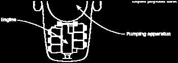
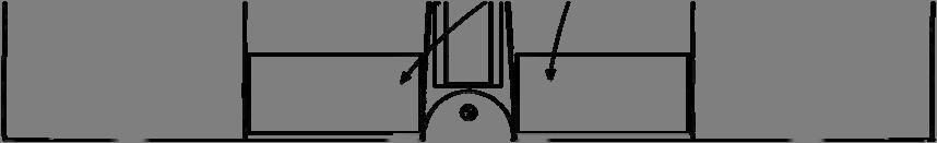
7 2. Configuration (MF) 2.1 Core systems configuration Having established the three core design types, initial design on the internal and external configuration of the aircraft could begin. Preliminary design focused around determining rough size, shape, and placement of the core systems necessary for basic aircraft functionality Propulsion Rough estimates were used to approximate the volume required for both fuel tanks and overall engine size, both based on historical data. The fuel tanks were represented by slender rectangular sections, while the engine was assumed to occupy a roughly cubic volume Payload As designated by the RFP, the aircraft would be required to utilize a self-contained pumping apparatus for liquid payload dispersion. The volume of payload both liquid and solid was also specified by the RFP, making preliminary modeling relatively simple. In order to achieve a more streamlined fuselage shape, the payload volume was constrained to a slender cylindrical or rectangular section. This proved to be greatly advantageous over the spherical shape of the pumping apparatus, which caused numerous design problems due to both its size and shape. Additionally, the solid and liquid payload volumes were superposed, with the intention of using a fixed hopper for the solid payload and a removable tank for liquids, the latter of which could be placed inside the former. This greatly reduced the anticipated fuselage size, which is preferable for low weight, a primary concern on this project Avionics A final volume block was allocated to the necessary avionics. This volume was treated rather amorphously, conforming to whatever space was available in the desired fuselage 6
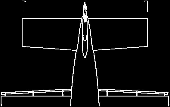
8 configuration. This would later be refined after actual avionics would begin to be selected. For the meantime, it provided a reasonable estimate for general sizing concerns. 2.2 External configuration The volumes and shapes determined from the initial systems analysis were then placed in several configurations. All configurations were built around anticipated static stability, placing the varying payload sections near the expected center-of-gravity of the overall aircraft. Several variations involving the placement of the pumping apparatus and the avionics bay were produced. However, after creating preliminary external structures to house the estimated volumes, it was quickly decided that the pump, with its spherical configuration would have to be placed near the front of the fuselage. Placing the spherical apparatus rearward resulted in either consistently thick fuselage sections or a bulge in the fuselage near the pump. Both conditions are detrimental to aerodynamic efficiency, and so any configuration locating the pumping apparatus in the aft fuselage were dismissed from the design. External structure was then developed around these initial volume arrangements, based on the three selected configurations: monoplane, biplane, and a blended wing body. Several 3D concept sketches were developed for each of these general configurations, with those with the most desirable characteristics being chosen for continued development. Commonality became a key concern for the biplane, as a complete redesign versus the monoplane would be cause for extensive amounts of additional analysis, which would not further the goal of determining whether a biplane or monoplane configuration was better suited to the design conditions. The finalized external designs are illustrated through use of dimensioned three-view drawings in Figures

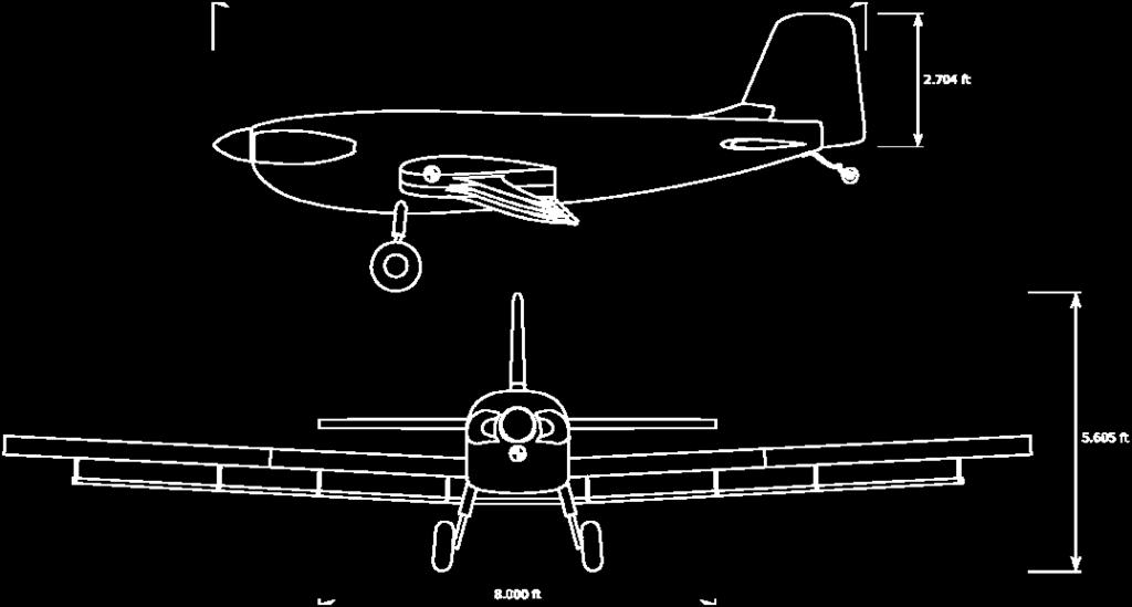


9 Figure 2.1 Monoplane configuration layout. 8

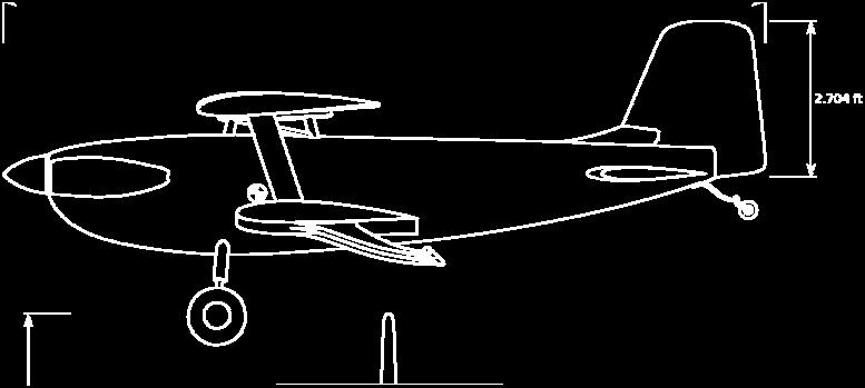


10 Figure 2.2 Biplane configuration layout. 9


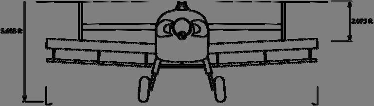
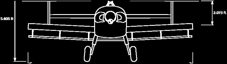
11 Figure 2.3 Blended wing body configuration layout. 10
12 2.3 Structural configuration Using data gathered by the Structures group, the basic underlying structure for each resultant external airframe shape was estimated. The structure was determined largely by the characteristic shape of the airframe as previously determined, and did not contribute significantly to the external designs. The structural data did, however, become vitally important in the later weight build-up and balancing operations. Please refer to Structures for more information. 2.4 Additional systems configuration Avionics After the preliminary airframe designs were completed, avionics began to be selected. This allowed for both a more accurate bounding volume for the avionics bay and an estimated weight value, which was used in roughly determining initial configuration positions Propulsion With an engine selected, the estimated propulsion bounding cube was replaced with an accurate model of the actual engine to be used by the aircraft, which allowed for significant airframe improvement in and around the engine area of the fuselage. Nacelles with air inlets were added to the sides of the cowling for the more conventional configurations, sheltering the engine cylinder heads from the elements while still allowing sufficient airflow to provide both power (through combustion) and cooling effects. Fuel consumption requirements were also calculated at this point, allowing the fuel tanks to be appropriately sized. The fuel tanks also began to conform to the wing geometry, instead of merely representing a necessary design constraint. 11
13 2.4.3 Payload delivery system An initial liquid payload delivery system was also designed, consisting of a length of piping outfitted with specialized nozzles at regular intervals. This structure was suspended beneath the wing, offset from the trailing edge. A number of brackets were utilized on each wing to support this added load, being spaced at intervals along the overall span. 2.5 Weight and balance Structural weight The primary concern during the weight build-up procedure was the overall weight of the airframe i.e., the empty structural weight of the aircraft. In order to best estimate this weight, significant cooperation was made between the Configuration and Structures groups. Skin thickness over all external surfaces was assumed to be a uniform 1/16 of an inch and made entirely of 2024 Aluminum. Wing ribs were placed uniformly throughout the structure, and were assumed to have an average cross-sectional area equivalent to 50% of the cross-sectional area at the mean chord of the wing. Additionally, the ribs were assumed to be 1/16 of an inch thick and made of 2024 Aluminum. The fuselage was assumed to be supported primarily by a set of ring frames along the length, which were also assumed to be made out of 1/16 inch 2024 Aluminum. The cross-sectional area of the ring frames was assumed to be 50% of the cross-sectional area of the fuselage at 2/3 of the length. Similar schemes were used for the small number of supporting ribs in the horizontal stabilizer and vertical tail structure. Additionally, I-beam cross-sections were used to estimate linear density for aluminum spars and stringers used through the wings and fuselage to add additional structural support and stiffness. Many of these estimates were purposely made higher than the anticipated actual values. This provides for any additional weight due to intermediary support structures, cables, linkages, 12
14 and any other unanticipated weight increases. Overall, such analysis yielded reasonable values with a much greater basis in physical reality than many general formulae presented in academia based on historic trends, which may or may not be applicable due to differences in materials and construction techniques Component weight Component weights were easily obtained from either stated values (e.g., the payloads) or from manufacturers published data (e.g.., the engine). Necessary structural members for components, including the engine firewall and the spray system support struts, were calculated in a manner similar to that outlined above for the overall airframe. Fuel mass was calculated using standard density for 100LL multiplied by the total fuel tank capacity. These values combined yielded overall payload, component, and fuel weights Center of gravity calculation In order to facilitate calculation of the center of gravity in all three dimensions, the standard Z-up coordinate system used in solid modeling was utilized, with all points referenced to the modeling datum. Using a series of software scripts, centroids for each major airframe and subsystem component were able to be calculated and plotted in modeling coordinates. Combined with the mass data from the weight build-up, these individual centroids were appropriately weighted, and the overall C.G. of the aircraft was able to be easily determined. It should be noted that the centroid calculations were based on homogenous materials with uniform, constant density throughout their volume. Any variations in density (e.g., due to different sections of material within a single structure or component) were assumed to be negligible; if this were not the case, the analysis would provide only approximate (and not exact) C.G. locations. 13
15 2.5.4 Static margin calculation Using the neutral point location determined by the Stability & Control group, the static margin was able to be calculated. By translating the neutral point to the modeling coordinate system, the static margin for each configuration was easily obtained. These values were then passed back to Stability & Control for further analysis Balancing In order to maintain positive static stability by at all times, it was dictated by the Stability & Control group that the C.G. must remain forward of the previously-calculated neutral point during the full range of flight conditions. In order to achieve this, numerous sub-systems were adjusted to balance out the overall aircraft C.G.; in fact, the fuselage was actually increased in length over its original (pre-balancing) configuration by nearly an inch in order to provide for sufficient component shifting to achieve the desired stability conditions. This increase allowed the engine to be seated further forward, pulling the C.G. significantly forward due to the large mass of the engine and propeller assembly. Additionally, this freed up an extra inch of longitudinal movement between the remaining subsystems housed within the fuselage. The finalized, balanced internal layouts for each of the three primary configurations can be seen through the use of cut-away drawings in Figure 2.4. The C.G. locations noted are those for the empty weight set-up. 2.6 Final configuration After numerous iterations due to airframe, airfoil, wing geometry, and other changes, the designs were externally finished. Further work was required in order to balance the internal configuration in order to maintain the necessary static stability. At each iteration point, the resultant geometry, weight, and C.G. data was passed off onto all other design groups for further 14

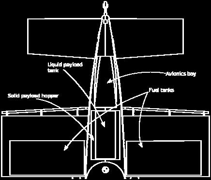


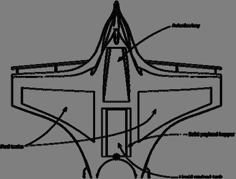
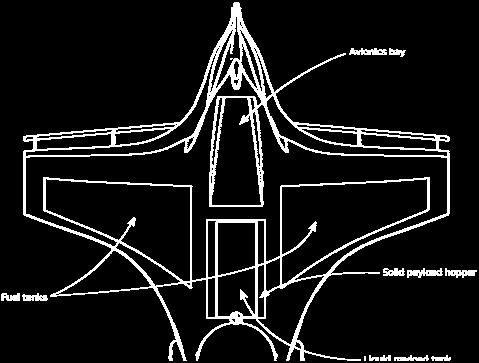


16 analysis and development. This continued in a mutual fashion until the configurations were finally finalized. Figure 6.4 Cut-away drawings detailing internal configuration for primary designs. 15
17 2.7 Landing gear trade study Typically, advanced-lift aircraft such as flying wings and blended wing bodies utilize some form of tricycle landing gear, as opposed to the taildragger (or conventional ) arrangement used here. Tricycle gear were considered for the BWB design, but were found to provide insufficient ground clearance due to the presence of the relatively low-handing spray booms on either wing. Utilizing a taildragger configuration allows for an allowable ground clearance with reasonably-sized gear. In contrast, a tricycle configuration would require much longer gear struts in order to provide sufficient ground clearance when pitching up during takeoff. In addition, tricycle configuration gear are typically not particularly robust in comparison to most tail dragger arrangements. This is of great importance due to the RFP requirement for this aircraft to operate on dirt, gravel, or other improvised airstrips. Such conditions produce much more stress on the landing gear in overall use, and are more suited to large main oleo or spring-steel struts with a spring-steel tailwheel than to the possibly more complex tricycle configurations, with more delicate steerable nosewheels. 2.8 Detailed analysis of payload delivery system Onboard Storage As the primary function of the aircraft is aerial application of solid particles and fluid pesticides, components that provided ways to deliver both types of product to the crops were needed. For the storage tank, a solid particle hopper with a funnel shape was designed. At the base of the tank was an auger to pull product down into the dispersion outlet. The fluid storage tank was designed to plug into the solid particle hopper. A hose that can be stored beneath the solid particle hopper connects to the fluid storage tank. The hose is then connected to a pump which pumps the fluid into the spray booms and out the spray nozzles. 16
18 2.8.2 Application Techniques After being pulled down from the solid particle hopper by the auger, the solid particles are released into the atmosphere through the dispersion outlet. The solid particle drop mechanism is purely a gravity fed system; the solid particles simply fall out of the aircraft. A fairing around the dispersion outlet helps to decrease the aerodynamic drag and also helps to produce an even spread behind the aircraft. The liquid product is applied through a series of nozzles on the boom below and behind the trailing edge of the trailing edge of the wing. From the fluid storage tank a pump pulls the fluid into the booms and then the fluid is sprayed on to the crop by way of the nozzles. The nozzles are an off the shelf product designed specifically for aerial application. 2.9 Future work General configuration The largest area to be addressed is that of more intricate modeling of the internal and external structure of the overall aircraft. With future work from the Structures group, the internal configuration of structural members can be established and actually calculated, as opposed to the estimation used for this analysis. This will also contribute to perfecting the internal arrangement of other subsystems, as they will be able to be precisely arranged according to the positioning of nearby structural members. All of this will be used to better balance the aircraft to not only achieve stability, but to achieve the smallest range possible of C.G. (and hence static margin) shift over the entire flight profile. The solid payload hopper will also be designed in detail to allow the liquid payload tank to mount securely using some sort of quick-release fastener system. Similarly, the access hatches for the payload and avionics will also be modeled for best user use with minimal detrimental effects on aerodynamics and structural concerns. 17
19 2.9.2 Payload delivery system Once an airplane configuration is selected the process of optimizing the spray system to suit the particular configuration can begin. The angle at which the nozzles are aligned with respect to the wing needs to be optimized for maximum coverage. The angle at which a particular nozzle is aimed with respect to the longitudinal axis needs to be optimized for maximum coverage as well. To reduce aerodynamic drag produced by the spray system, a streamlined spray mechanism needs to be designed. Once the streamlined spray mechanism is designed a trade study on production cost effectiveness vs. drag reduction will need to be done. The method for dispersing solid particles needs to be investigated as worries about coverage are inherent in the use of a single dispersion outlet. Possible solutions to the solid particle dispersion problem include creating more dispersion outlets along the wingspan of the aircraft and dropping the solid particles over that greater length, which would in turn produce more coverage for the solid particle dispersion. Another, simpler solution would be to engineer a divergent duct designed for optimum coverage with a certain size of particulate matter. 3. Structures and Loads (MD) 3.1 RFP Requirements The RFP performance demands as related to the structural design area are relatively straightforward. First, the aircraft is supposed to be of a fixed wing design. Additionally, the craft s payload will consist of 235 or 300 pounds of liquid or solid material to spray over the field, operating just above ground level or at 1000 feet without a payload. Given these parameters, these payload requirements will not put tremendous strains on any common aircraft 18
20 structure. Instead the challenge will be to eventually optimize the design in such a way as to be as efficient, simple and cost effective as possible. 3.2 Structural Considerations The main structural consideration for any aircraft is both designing the individual parts to withstand the loadings it is expected to undergo and maintaining the load paths throughout the entire aircraft to transfer the load throughout to achieve an efficient design. This necessitates that the structures in and connecting the fuselage, wings and control surfaces of the aircraft be properly configured. However, because of the standard tail configuration used in the designs the control surfaces are not intended to generate any significant percentage of lift for the aircraft. Because of this the main concerns for the design, at least at present, are in making sure that the wing is able to support the lift force of the aircraft, transfer it through the fuselage and make sure the fuselage is able to properly support all of the internal payloads Fuselage Structures In each variant, in order to accommodate the payload, sensors, pumping systems and engine it was decided that a ring frame structure would be best for the fuselage. The other main choice of a wing-box carry through configuration would have either forced the fuselage to become larger to accommodate the internal payload or require other payload modifications that would have adversely affected the center of gravity of the aircraft. In order to transfer load along the fuselage between the ring frames, again to best fit around the internal payloads, stringers along the length of the fuselage will be used. The stringers at the bottom of the fuselage will simply be thicker in order to directly carry the weight of the internal payloads, whereas the stringers at the top can be relatively thin as they have little load to carry. The vast majority of these structures will be made out of aluminum, as it is light, relatively strong and cheap. Certain 19

21 structural elements that require greater reinforcement will be supplemented with steel structure to add stiffness Wing Structures The wing of each variant has to be designed in such a way that it can withstand the forces due to lift and drag on the wing as well as the twisting moment generated by the varying lift distribution along the wing cross section. This requires that the wing both have main spars going down its length and that the skin on the wing be thick enough to carry most of the moment on the wing, which is normal in a thin walled structure such as an airplane wing. Ribs will be needed near the wing root where the fuel tanks are located in order to transfer the weight of the tanks to the wing spars effectively, however as the wing is meant to have three spars there is little need for ribs past the fuel tank locations. This is because the only additional attachments to the wing past the fuel tank areas will be the sprayers, which will add negligible loading. A diagram of the wing and fuselage carry through structure is shown below in Figure 3.1 Figure 3.1 Basic wing/fuselage structural configuration isometric view. 20
22 Additionally, the monoplane variant s wingspan is too long to fit the transport requirements of the RFP. This necessitates that the portion of the wing past the fuel tanks be folding. However, designing the folding wings is too complex for this stage of development. Also, while it is difficult at this time to calculate precise wing loading values one can get a rough estimate of the forces and moments at the wing roots by assuming that the wing generates the whole lift of the aircraft and that lift is distributed uniformly along the wing. By then treating the wing as an Euler-Bernoulli beam one can then calculate rough reaction values at the wing root that are likely to occur in steady and level flight, which are shown below in Table 3.1. Table 3.1 Wing Root Forces and Moments at Maximum Payload Variant Root Force (lbf) Root Moment (lbf-ft) Monoplane Biplane (upper) Biplane (lower) BWB n/a n/a Landing Gear Landing gear is of course necessary to have on any aircraft. Given the relatively low overall weight of the aircraft and the need for the ability to land in rough fields, keeping the configuration as simple as possible was ideal. All the variants were designed as tail draggers because it is a configuration that is simple and cheap to build and also easy to control on the ground, which is why it is found on many manned crop dusters. Therefore the only question remaining was what type of landing strut the two forward wheels had. The main choices for this include solid spring, levered bungee or oleo shock-strut designs. All of these are comparatively simple and robust enough to withstand a rough landing, but given that the aircraft is unmanned the shock absorbing requirements for each are somewhat more relaxed than for a manned aircraft so long as the sensors and other payloads remain intact. In order to best withstand the shock 21
23 loads of landing the gear is going to be made out of steel regardless of the configuration. Currently the preferred design is that of the oleo shock-strut, because the solid spring design tends to be heavier while the levered bungee generates more drag than the others. However, these configurations will be compared in depth to find the optimal choice later once weights and configurations are fixed; the general location can be seen on the previous variant images. 3.3 V-n Diagrams Having an idea of the maximum loading that an aircraft is expected to undergo during flight at various velocities is essential to properly designing the structure of the aircraft. This can be done through the creation of V-n diagrams, the calculations for which are given in the code in Appendix Y, which give a visual representation of the maximum g-loading that the aircraft is expected to experience and survive during flight. Pictured below are the V-n diagrams for each of the different variants at the maximum weight of full fuel and solid payload. Figure 3.2 Monoplane variant V-n diagram (max weight). 22
24 Figure 3.3 Biplane variant V-n diagram (max weight). Figure 3.4 Blended wing body variant V-n diagram (max weight). From these one can see that there is only a short range of velocities in which the maximum loading will occur above cruise velocity; however the wings must still be designed to 23
25 take this loading. Also, it is apparent that gust loadings during normal flight are of minimal load impact, which is partly due to the lower speeds the aircraft is flying at. 3.4 Trim Diagrams The V-n diagrams only give the maximum g-loading for the aircraft though; in order to calculate the actual normal and axial loads, corresponding to the lift and drag, expected on the wing one needs to look at the aerodynamic values versus angle of attack. This is done by manipulating the lift, drag and moment coefficients in order to find the force coefficients on the wing during normal flight, which is done by the code in Appendix Y. These force coefficients versus angle of attack for each aircraft variant are shown in the figures below. These diagrams are also made under the simplifying assumption that the horizontal tail is parallel with the wing as further design, specifically tail airfoil selection, is needed to do more realistic calculations. Figure 3.5 Monoplane variant trim diagram. 24
26 Figure 3.6 Biplane variant trim diagram. These force coefficient values can in turn be multiplied by the appropriate max load factor as given by the V-n diagram and design values to find the maximum force that the wing structure must be able to withstand. However, doing this design and calculation was outside the scope of current efforts. Further, the difficulty of attempting to calculate what the distribution of lift over the blended wing body would be, given the limited number of design tools available, made doing a similar trim diagram for the blended wing variant time prohibitive. 3.5 Material Trade Study The main trade study that could be performed at this stage of design was in choosing the materials to be used in the structure of the aircraft. Because of increasing use of composite materials in all types of aircraft design, it was necessary to compare modern fiberglass and carbon fiber composites against more traditional material choices such as aluminum and steel. Looking at the most relevant mechanical properties in Table 3.1 of elastic and shear modulus (E and G respectively), even when taking density into account, it becomes apparent that fiberglass 25
27 cannot offer the same performance as aluminum in the structure of the aircraft. Only continuous carbon-fiber composites offer specific properties that can rival steel and aluminum. However, this is highly dependent on the ply orientations and therefore one does not get the same combination of elastic and shear modulus as with the bulk metals. Furthermore, the much higher costs of carbon composite versus metal and the greater complexity in utilizing it means that it is unsuited for this design as it is supposed to be simple and cost effective. Therefore aluminum and steel are the materials of choice for this aircraft. Carbon composites would only be used if aircraft weight became a serious problem later on in development. Table 3.2 Material Mechanical Properties Ref. [2] Material E (GPa) G (GPa) density (kg/m 3 ) Fiber fraction Ply Orientation Aluminum n/a n/a Steel (AISI 4130) n/a n/a Discontinuous Fiberglass n/a n/a n/a Continuous Fiberglass /90 5x /-45 5x /45 6x4 Continuous Carbon Fiber /45 7x /45 4x6 3.6 Future Work After deciding upon which aircraft variant to use, there is much more structural work to do. After a more detailed lift profile for the wing design is obtained, it will be possible to thoroughly calculate the forces and moments along the wing structure and fix the internal structure accordingly to sustain those loads with the desired margin of safety. Further, these values can be used to design the wing and ring frame interface at the wing root to properly transfer the loads across the fuselage and support the weight of the fuselage itself. Further, once 26
28 the center of gravity and therefore location of the internal payloads is fixed, the fuselage structure dimensions can be calculated in detail as well. After this is done, and one has fixed the weight of the aircraft structure and the rest of the craft, the loads the landing gear must sustain can then be analyzed in detail for each different configuration, from which the most appropriate selection can be made. 4. Sizing Analysis and Concept Selection (TF) 4.1 Mission Profile The mission profile was well documented and was even included in the RFP. However, there were a few modifications that could be made to the mission profile in the RFP. For example, it was up to the team to determine if the aircraft would have to travel back to the airstrip after its payload drop or if the mission would end close enough to the runway where this was not a consideration. Our team decided to go with the worst case scenario where the aircraft would have to travel some distance before reaching the runway. Another assumption that was made was that the airplane would retain its payload during the flight. This assumption would also represent the worst case scenario and gave the team an idea of what the very upper weight limit would be for the aircraft. This mission profile can be seen in Fig Figure 4.1 Payload delivery mission profile. 27
29 The RFP also mentioned another mission profile that would act as a ferry flight where the plane could be transferred between missions. The distance for this mission was specified in the RFP to be one to two miles, so the team decided on the two mile range to account for the worst case scenario. The mission profile for the ferry flight can be seen in Fig Initial Sizing Figure 4.2 Short ferry flight mission profile. 4 5 Initial sizing calculations were conducted using Raymer (Ref [1]). The initial sizing method presented in these references allows the design team to achieve an estimate of the take off gross weight (W 0 or TOGW) so that further analysis can be done on different aspects of the aircraft. If additional weight is added over the initial estimate it is likely that the plane will still fly, but not up to specifications. For this analysis, the TOGW was split up into three categories: fuel weight, payload weight, and empty weight. The payload weight comes from the RFP and depends on what kind of cargo the plane is carrying. The analysis was done for both types of payloads; however the design team is going to use the heavier payload in its design considerations because that is the maximum weight. The initial sizing depends a lot on the selected mission profile and how it is broken up. The team used the same mission profile as described in section 4.1 and used each leg to perform weight fraction analysis. Once each segment s weight fraction was found, they were multiplied 28
30 together to get the final weight fraction. From this the fuel fraction can be found and a safety factor of 1.06 was applied to account for reserve and trapped fuel. Takeoff, climb and landing fractions were taken from historical data in Table 3.2 of Ref [1]. The descent portions of the flight were considered part of the cruise leg, so their weight fractions were assumed to be one. The cruise portion distance was calculated using data from the RFP and some simplifying assumptions. The RFP specified a field size of 1000 ft by 0.5 mi. For the initial sizing, the design team decided to estimate the distance to spray the field by taking the area sprayed per pass and adding the turn distance times the number of passes. A second cruise portion was added after the spraying mission to account for the aircraft returning to the landing strip and to give the maximum possible distance that the aircraft would have to travel. This distance was estimated to be around 1000 ft, or the width of the field. The weight fraction for both cruise segments was calculated using the Breguet range equation in Ref [1]. The empty weight fraction was found using the equation found in Table 3.1 of Ref [1]. Historical values are given for different parameters and then using an initial guess for the TOGW, the empty weight fraction can be found. To be thorough, a survey of historical agricultural aircraft was also taken and the results were compared to what was obtained using Raymer (Ref [1]). The results, along with what the empty weight fraction for our proposed design (based on the TOGW determined later) are presented in Fig 4.3 and Table
31 We/W y = -5E-10x 2 + 5E-06x TOGW (lbs) Figure 4.3 Plot to compare empty weight ratios. Table 4.1 Data for the Comparison of Empty Weight Ratios Plane TOGW (lb) Empty Weight (lb) W e /W 0 AT-401B AT-402A/B AT-502A/B AT AT-802A AT-802F PAC Cresco An An M-18 Dromader PZL-106 Kruk PA-25 Pawnee PA-36 Pawnee Brave GA200 Fatman Cessna G-164 Ag Cat Ayres Thrush CallAir A Design Point
32 The weight fractions were then used to calculate the fuel fraction that each configuration needed and then the TOGW was guess iteratively until the guess approximately equaled the result from the equation based on the empty weight fraction. A number of design parameters were chosen based on the airplan configuration and those are presented below in Table 4.2. Each configuration had many parameters in common, such as C D0, SFC, and propeller efficiency. The spray distance is different for each configuration because of the wingspan that is required to produce the desired performance and this seems to be the biggest difference between the configurations. A summary of the iterated TOGW and weight fractions are also tabulated in Table 4.3. Finally, a summary of the mission segments and their weight fractions are presented in Table 4.4. Table 4.2 Input Data for Initial Sizing Parameter Conventional Biplane Blended Wing Body Operating Altitude (ft) Operating Speed (ft/s {mi/hr}) 168 {114.5} 168 {114.5} 168 {114.5} Operations Distance (ft {mi}) {25} {50} {50} Turning Speed (ft/s {mi/hr}) 168 {114.5} 168 {114.5} 168 {114.5} Minimum Turning Radius (ft) Turn Distance (ft {mi}) {3.42} {3.42} {3.42} Return Distance (ft) Spray Time (seconds {minutes}) 893 {14.89} {27.98} {27.98} C D e AR SFC (cruise) (lb/hr/bhp) Prop Efficiency (cruise) (L/D) max C L,max Solids Payload Weight (lb) Liquids Payload Weight (lb)
33 Table 4.3 Initial Sizing Results for Input Data Parameter Conventional Biplane Blended Wing Body TOGW solids (lb) TOGW liquids (lb) W e /W W f /W Solids Mission Fuel Weight (lb) Liquids Mission Fuel Weight (lb) Max Fuel Capacity Needed (gal) Leg 0 Table 4.4 Summary of Mission Segment and Weight Fractions Height (ft) Range (miles) V (ft/s) SFC (lb/hr/lb) Assume Wi/Wi-1 Wi/W0 Segment (L/D) Warm up and taxi 0 NA NA NA NA Included in Takeoff Takeoff 0 NA NA NA NA Historical fuel fraction Climb variable NA NA NA NA Historical fuel fraction Descent is part of 3 Descend variable NA NA NA NA cruise Cruise (L/D)=(L/D) max Climb variable NA NA NA NA Historical fuel fraction Cruise (L/D)=(L/D) max Descent is part of 7 Descend variable NA NA NA NA cruise Land 0 NA NA NA NA Historical fuel fraction Constraint Analysis The next step in preliminary analysis was the Constraint Analysis, which is used to determine wing loading and power to weight ratios. The Constraint Analysis was performed assuming that the plane was in the conventional configuration, but the constraint diagrams should be similar for all of the different designs. The Constraint Analysis was done using the results and assumptions from the initial sizing. The assumptions and conditions that were used in the Constraint Analysis are 32
34 summarized below in Table 4.5. The equations for conducting the Constraint Analysis are located in Anderson and Raymer (Refs [3] and [1]). The design team decided to perform the Constraint Analysis on the most important parts of the aircraft s flight, which include the takeoff, landing, turning, and cruise. The plot resulting from the constraints is shown in Fig 4.4. Constraint Takeoff Landing Table 4.5 Summary of Constraint and Assumptions Assumptions 750 feet, standard sea level (SSL) conditions, thrust(power) is much greater than the drag and ground friction 750 feet, standard sea level (SSL) conditions, C L,max,L is greater than C L,max Sustained Turn Load factor of 2.5, turn velocity equals operating velocity, SSL conditions, C D0 =0.03 Cruise SSL conditions, velocity>1.3v stall, C D0 =0.03, e 0 = Selection of a Design Point From Fig 4.4, it is easy to see that the design space will be constrained by the sustained turn and landing constraints. The design point that the team selected is located at a wing loading of 16 lb/ft 2 and a power to weight ratio of bhp/lb. The design point was selected here so that even if the plane changes, the constaints will not be violated. This design point also decides a number of design parameters which are summarized below in Table 4.6. The results from the design parameters also influenced the choice of design point because if the wing loading were lower there would be less thrust required, but the wings would have to be very large. The parameters were tabulated for both payload cases, however the heavier TOGW is more important because that is the maximum. Table 4.6 Summary of Design Parameters Given by Constraint Analysis TOGW (lbs) Power Required (bhp) S ref Wingspan (ft) Chord Length (ft)
35 Power to Weight Ratio (P/W) Wing Loading (W/S) Cruise Constraint Takeoff Constraint Sustained Cruise Constraint Landing Constraint Design Point Figure 4.4 Constraint analysis diagram with design point selected. 5. Performance (TF) 5.1 RFP and Other Requirements The RFP specified a number of performance values that must be met in order for the design to be considered successful. There were a number of other parameters that were not specified by the RFP so those were chosen so that the other design team members could create a workable design. These specifications are outlined below in Table 5.1. Table 5.1 Summary of Performance Requirements Requirement Value Source Operating Speed 1.3*V stall RFP Takeoff Distance (ft) 750 RFP Landing Distance (ft) 750 RFP Operational Altitude (ft) 20 RFP Ferry Altitude (ft) 1000 RFP Ferry Distance(mi) 2 RFP Turning Radius (ft) < 250 Design Team 34
36 As was discussed in section 4 the three important requirements that must be met are the takeoff and landing distance and the cruise distance to cover the fields. The other parameters would be derived from what the plane could do based on the other performance characteristics. The ferry mission could also be easily met if the three main specifications were because the weight for the ferry mission is much lighter and the distance is also less than a regular payload drop mission. The only requirement that the design team felt the need to specify was a turning radius. The value of 250 ft was chosen because of the width of the field. If the plane didn t meet this requirement it would not jeopardize the success of the payload dropping mission, however a more maneuverable plane would make this mission easier and quicker to accomplish. 5.2 Design Parameters Investigated To meet the requirements the most important parameters of the airplane are the aerodynamics and structures. The structures portion will deal mainly with the wing loading and the load factor that is applied during the turn. The aerodynamics performance parameters that affect the critical performance requirements of the plane are C L,max, C D0, and AR. The amount of wing loading is critical to almost every aspect of how the aircraft performs, but is particularly important in the case of takeoff and landing. A higher wing loading means that it is harder for the airplane to get off of the ground and also makes it harder to land in a set distance. Because of the requirements in the RFP, our vehicle will need to have a low wing loading. The load factor is important in determining turning radii and speeds. To achieve the desired performance the load factor will have to be in the medium range. For the cruise portion of the mission, it is critical to have a high lift to drag ratio (L/D), which stems from a high C L,max and C D0 according to the equations in Raymer (Ref. [1]). When 35
37 C D0 is increased it decreases the maximum speed and range of the aircraft. C L,max has a big effect on the stall speed of the aircraft as well as the takeoff and landing distances. When C L,max is increased, the landing distance and takeoff distance decrease and the stall speed decreases as well. Overall it is good to have a higher C L,max because the airplane will be more efficient and less likely to stall. However one downside to having a high C L,max is that the cruise speed is decreased. The cruise effects of a high C L,max can be offset by increasing the aspect ratio (AR) of the wing to reduce the drag due to lift (induced drag or C Di ). 5.3 Takeoff and Landing Performance The equations that were used to determine the takeoff and landing performance came from Raymer and Anderson (Refs. [1] and [3]). The equation accounts for the effects of wing loading, ground friction, thrust, induced drag, and zero-lift drag. A spreadsheet was created in Excel that took the values for each parameter and plugged them in to give the takeoff distance for a given set of values. Different values were chosen for the velocity until a reasonable C L,max was obtained. The analysis was done using the weight buildup values from Configuration and the aerodynamics data from Aerodynamics. The values for the takeoff and landing distances were then compared to what they were with the chosen design point from the Constraint Analysis. A summary of this comparison can be found in Table 5.2. Table 5.2 Summary of Takeoff and Landing Distances Initial Build-up Revised Configuration Weight (lbs) Weight (lbs) Initial takeoff distance (ft) Revised takeoff distance (ft) Initial landing distance (ft) landing distance (ft) Conventional Bi-Plane Not Available Blended Wing Body
38 5.4 Sustained Turn Performance Throughout the payload drop portion of the mission, the aircraft will be turning after every pass, which makes the turning performance crucial to how well it will complete the mission. The analysis used to determine the performance come from Anderson (Ref [3]). The maximum load factor allowable by the thrust of the engine was calculated and from that the turning stall speed, minimum turning radius, and turning velocity were calculated. Results from this analysis are presented in Table 5.3 below. Table 5.3 Summary of Turn Performance Based on Maximum Thrust Configuration n max, thrust V stall (ft/s) Turning Radius (ft) Conventional Bi-Plane Blended Wing Body Other Miscellaneous Performance Parameters Several other performance parameters were also specified in the RFP, but do not merit their own section. Those parameters include the operating speed, the total mission time, and drag for the segments of flight. The operating speed was specified in the RFP and was calculated using an equation from Anderson (Ref [3]). Drag for each segment was based on the classic drag equation using the dynamic pressure, wing area, and drag coefficient. These are all tabulated below in Table 5.4 and 5.5. Table 5.4 Summary of Miscellaneous Performance Parameters Configuration Mission Time (min) V stall (ft/s) Minimum Operating Speed (ft/s) Turn Rate (rad/s) Conventional Bi-Plane Blended Wing Body
39 Table 5.5 Summary of Drag for each Segment Configuration Cruise Drag (lbs) Turn Drag (lbs) Takeoff Drag (lbs) Landing Drag (lbs) Conventional Bi-Plane Blended Wing Body Trade Studies Two trade studies were performed in an attempt to shed light on the cause of the shortcomings of the designs, particularly with the takeoff and turning radius specifications. The takeoff trade study had C L,max altered to gauge the effect that it would have on the takeoff distance. From the trade study it can be concluded that a lower C L,max is beneficial to the takeoff distance. The results can be seen in Fig 5.1. For the turning radius study, C D0 was altered so that its effect on the loading factor, and therefore the turning radius could be seen. The effect of C D0 was not as profound as the results for C L,max however the study still shows that the lower the C D0 is the smaller the radius can be. This makes sense because if less thrust is being nullified by drag it can then be used to power through a turn. The results of that trade study can be seen in Fig 5.2. Both trade studies were performed for the conventional configuration. Takeoff Distance (f t C L Figure 5.1 C L trade study for the takeoff distance. 38
40 Turn Radius (ft C D0 Figure 5.2 C D0 trade study for the turning radius Future Work Since the takeoff and turning requirements for the RFP were not met it is essential that those are the first specifications that are looked into further so that they can become optimized and fall within the desired range. The mission profile has been somewhat simple so far and therefore in the future a better estimate of the performance can be obtained by discretizing the mission profile further. Other performance characteristics that should be looked at in the future include power available, and by extension, climb rate. While these parameters are not essential to the RFP, the fuel consumption and overall mission time could depend greatly on these parameters. 6. Aerodynamics (TL) 6.1 RFP Requirements, Initial Sizing, and Constraint Analysis While the RFP requirements do not immediately constrain the aerodynamic design in any fundamental way, the previously completed initial sizing and constraint analyses provided basic estimates of the wing geometry for the monoplane. The large span of the monoplane s wings 39
41 requires a folding-wing design to ensure that the monoplane will fit on standard roads (a requirement of the RFP). The only other RFP requirement with aerodynamic consequences is the 750 ft takeoff/landing distance specification, which affects the design through performance considerations. 6.2 Airfoil Selection Before making additional design choices for any of the variants, the NACA 2412 airfoil was selected for the wing of the monoplane, both wings of the biplane, and the wing portion of the BWB. This airfoil was chosen for its relative simplicity, and its reasonable and welldocumented performance characteristics at the flight conditions specified by the RFP. Additionally, a single airfoil section was chosen for the wing sections of all three variants in order to standardize the basis for comparing their aerodynamic performance. The airfoil chosen for both the horizontal and vertical tail sections of all three aircraft was the NACA This airfoil was also chosen due to its relative simplicity, well-known performance characteristics, and symmetric shape. 6.3 Wing/Fuselage Geometry In addition to the initial sizes determined by the Constraint Analysis, several wing design choices were made for the monoplane to improve both aerodynamic performance and overall stability. A gradual geometric twist of 3 deg was added to each wing, such that the tip airfoil sections are angled downwards with respect to the root airfoil sections. This ensures that the root of the wing will stall before the tip during a high angle of attack maneuver, allowing outboard control surfaces to function even if a portion of the inboard wing has stalled. A positive dihedral of 3 deg was also added to the wings to ensure roll stability (Ref [1]). This dihedral also helps ensure that the wingtips of the low-mounted wings will not strike the ground during a less than 40
42 ideal landing. The angle of incidence of the wing was set to 3 deg, in order to achieve a reasonable attitude orientation at cruise. Finally, sharp-cornered wingtips were used to prohibit the free flow of air around the wingtip, weakening any wingtip vortices formed, hence reducing induced drag without the need for heavier and more complicated winglets. 6.4 Aerodynamic Characteristics Monoplane Variant The required C L for the monoplane variant can be determined at the various flight conditions in the mission profile by using equation A.4.1. For this equation, the required lift is assumed to be roughly equal to the weight of the airplane (as supplied by Configuration), and approximate velocities supplied by Performance are used. For a cambered airfoil, the relationship between C D and C L can be determined via Equation 6.1. C D = C Dmin + K(C L - C Lmin drag ) 2 (6.1) Solving for the unknown variables in this equation is a lengthy process, involving many of the equations in Ref [1] Chapter 12, and briefly summarized here. K is determined using Equation A.4.2 and A.4.3. C Lmin drag is determined using equations A.4.4-A.4.7 and NACA 2412 experimental airfoil data (Ref [3]). C Dmin in Equation 6.1 is equal to C D0, and was first estimated using Equation A.4.8, and then analytically determined using the component build-up method outlined in Ref [1], and corresponding to Equations A.4.9-A The component breakdown of C D0 for the monoplane is shown below in Table 6.1. Table 6.1 Component Drag Buildup for Monoplane Component C D0 % C D0 Total Fuselage Wing V-Tail H-Tail Cowlings
43 Landing Gear Sprayers Propeller Flaps Total After initial analysis was completed assuming that flaps were not installed on the TE of the monoplane, performance considerations necessitated the addition of flaps to the design. These flaps were sized according to equation A.4.22 and Chapter 16 of Ref [1]. The effect of these flaps on C D0 and C Di is accounted for through equations A.4.23-A Additionally, ground effect was accounted for at takeoff and landing via equation A The results of this analysis yield the aerodynamic characteristics listed below in Table 6.2 for all RFP flight conditions. Table 6.2 Aerodynamic Characteristics for Monoplane Flight Condition Velocity (ft/s) Lift Required (lb) C L C D0 C D L/D Take-Off Payload Drop Turn Cruise Landing Biplane Variant Analysis of the biplane aerodynamic performance is similar to the analysis undertaken for the monoplane. However, a simpler form of the relationship between C D and C L is used, shown below in equation 6.2. This was done because it serves as a reasonable approximation of equation 6.1 during the conceptual design process. C D = C D0 + KC L 2 (6.2) 42
44 C D0 for the biplane is calculated in the same manner as it was for the monoplane, and the component values are below in Table 6.3. The wing combination unsurprisingly results in an increased C D0 when compared with the monoplane. However, C D0 for the biplane is only 4% larger than for the monoplane, this small difference is due to the lack of flaps on the biplane configuration, as flaps comprised approximately 9% of C D0 for the monoplane. Table 6.3 Component Drag Buildup for Biplane Component C D0 % C D0 Total Fuselage Top Wing Bottom Wing V-Tail H-Tail Cowlings Landing Gear Sprayers Propeller Wing Supports Total K can theoretically be calculated using equations A.4.2 and A.4.26 from Ref [1]. However, using equation A.4.26 with the geometry of the biplane yields an Oswald s efficiency factor of >1. This is theoretically impossible, and thus an estimated e value of.75 was used instead. This value is suitably lower than e for the monoplane, however it is purely an estimate, and thus the C Di calculated for the biplane is likely subject to non-trivial flaws. The aerodynamic characteristics at the various flight conditions are below in Table 6.4 for comparison. Table 6.4 Aerodynamic Characteristics for Biplane Flight Condition Velocity (ft/s) Lift Required (lb) C L C D0 C D L/D Take-Off Payload Drop Turn
45 Cruise Landing As is apparent from the table, C D is significantly larger than for the monoplane. This is partially explained by the decrease in e relative to the monoplane. However, the much smaller aspect ratio for the biplane is the larger cause behind the higher C Di it experiences Blended Wing Body For the analysis of the BWB, the airframe was simply treated as three airfoils molded together. Equation 6.2 was used again to represent the relationship between C D and C L for the BWB. The tabulation of C D0 is shown below in Table 6.5 Table 6.5 Component Drag Buildup for Blended Wing Body Component C D0 % C D0 Total Fuselage Wing Wing V-Tail Landing Gear Sprayers Propeller Total As expected for such a streamlined shape, C D0 is lower than both the monoplane and biplane, yielding a value that is 36% lower than C D0 for the monoplane. Aerodynamic characteristics for the BWB are tabulated below in Table 6.6. Despite the BWB s smaller C D0, the aircraft s total C D quickly grows larger than that for both the biplane and monoplane at equivalent C L values. This is due in largely to the small span of the craft, which results in small equivalent aspect ratios for both the main wing section and the fuselage wing section. This small aspect ratio results in a large induced drag for the craft. 44
46 Table 6.6 Aerodynamic Characteristics for Biplane Flight Condition Velocity (ft/s) Lift Required (lb) C L C D0 C D L/D Take-Off Payload Drop Turn Cruise Landing As is apparent from the table, C D is significantly larger than for the monoplane. This is partially explained by the decrease in e relative to the monoplane. However, the much smaller aspect ratio for the biplane is the larger cause behind the higher C Di it experiences Blended Wing Body For the analysis of the BWB, the airframe was simply treated as three airfoils molded together. Equation 6.2 was used again to represent the relationship between C D and C L for the BWB. The tabulation of C D0 is shown below in Table 6.5 Table 6.7 Component Drag Buildup for Blended Wing Body Component C D0 % C D0 Total Fuselage Wing Wing V-Tail Landing Gear Sprayers Propeller Total As expected for such a streamlined shape, C D0 is lower than both the monoplane and biplane, yielding a value that is 36% lower than C D0 for the monoplane. Aerodynamic characteristics for the BWB are tabulated below in Table 6.6. Despite the BWB s smaller C D0, the aircraft s total C D quickly grows larger than that for both the biplane and monoplane at equivalent C L values. This is due in largely to the small span of the craft, which 45
47 results in small equivalent aspect ratios for both the main wing section and the fuselage wing section. This small aspect ratio results in a large induced drag for the craft. Table 6.8 Aerodynamic Characteristics for Blended Wing Body Flight Condition Velocity (ft/s) Lift Required (lb) C L C D0 C D L/D Take-Off Payload Drop Turn Cruise Landing Drag Polar and Final Aerodynamic Selection The C L versus C D plots for all three variants are plotted below in Figure 6.1. Conventional Bi-Plane Blended Wing Body C L C D Figure 6.1 Drag polar for all three variants. As expected from the previously discussed data, the monoplane has the greatest L/D ratio at almost all C D values. Only when C L is vey low does the BWB have a better L/D ratio. This is the expected behavior, because the majority of the BWB s drag is due to induced drag. The 46
48 biplane experiences marginally better performance at high C D values over the BWB, however it is never outperforms the monoplane. Thus from an aerodynamic standpoint, the monoplane variant is the performs best, easily surpassing both the BWB and biplane. The results indicate that the aspect ratio for both the BWB and biplane are far too small to achieve a reasonable level of performance. Increasing the span of both aircraft to a value similar to that for the monoplane would likely decrease the aerodynamic performance gap that currently exists between them. 6.6 Aspect Ratio Trade Study The effect of small aspect ratio on the biplane and BWB variants was made obvious in the previous analysis, and a trade study examining the effect of aspect ratio on the performance of the monoplane is a natural extension of this discovery. As aspect ratio is varied from 6.65 to 1.7 for the monoplane, C D0 stays constant while C Di steadily increases. Figure 6.2 below makes this readily apparent; as aspect ratio is decreased from 6.65 to 3 the drag polar curve squeezes inward as L/D decreases at all values of C D. Further reducing A to 1.7 causes C D to increase again for equivalent C L values, and at A=1.7 the monoplane C L v. C D curve looks very similar to that for the BWB. 47
49 Monoplane, A=6.65 Blended Wing Body Monoplane, A=1.7 Monoplane, A= C D Figure 6.2 Drag polar for varying monoplane aspect ratio. 6.7 Future Work The actual lift created by the wing at a given Reynolds number for the monoplane should be determined to ensure the airplane will takeoff when expected. Additionally, optimization of the wing span should be performed, as the added cost and complexity of a folded wing is undesirable. Also, enhancement of the sprayer bar to reduce separation behind the cylinder should be considered, as this would greatly decrease C D0. Finally, optimization of the take-off and landing speeds with the ultimate goal of removing the flaps should be explored in order to reduce the drag, weight, and cost penalty associated with these devices. 48
50 7. Propulsion (KP) 7.1 RFP and Other Requirements The RFP simply states that the engine requirements are that it be a widely available off the shelf engine that, based on technology available today, is best for the design. The process of selecting an engine was affected by other requirements in the RFP such as the need to carry the extra weight of the expendable payload. A wide range of studies were done to determine which engine would be best for the design. 7.2 Engine Selection Before actually selecting the engine type, a range of crop dusting and other light aircraft were looked at in terms of what engines they used with respect to their weights. Using the data from the initial sizing analysis and historical data from the aforementioned research, it was found that an engine with approximately 100 horsepower would be needed to support the design. Since all of the design configurations are light weight, the use of multiple engines or jets was dismissed immediately due to lack of need and impracticality. The engine types that were researched were internal combustion and electric. Research was done on the Sonex Electric Airplane concept, which has a fully electric engine that has a 24 hour charge cycle that gives one hour of flight. This system provides the approximate equivalent of 80 horsepower. This would be a very good selection for this mission profile if it were more widely available and slightly more powerful. An area for future work in this project would be looking into using an electric motor such as this one. Since the Sonex engine is still a concept model however, it was best for this design to choose a different engine. Electric propulsion was therefore dismissed due to a lack of availability. 49
51 Several internal combustion engines with a power output close to the required value were researched, and the Jabiru 3300 was chosen from the following list of candidates. Table 7.1 Candidate Engines Ref [6] Maker Model Horsepower Cruise RPM Weight (lbf) P/W (hp/lbf) Rotax 912 UL ULS Aeroconversions AeroVee Lycoming O-235-C O-320-A Jabiru Wankel LCR-814 TGti Table 7.2 Jabiru 3300 Specifications Ref [5] Maker Jabiru Model 3300 Cylinders 6 Displacement 200 cubic inches Bore 3.84 inches Stroke 2.91 inches Weight 180 lbf Power 2750rpm Fuel Cons. 5 US 75% Engine Power The Jabiru 3300 aircraft engine puts out 100 horsepower at 2750 rpm, and is capable of a maximum power output of 120 horsepower at 3300 rpm. One of the prime reasons it was chosen over the other candidate engines is the extra power that it can produce Engine Power to Weight The Jabiru 3300 s power to weight ratio is 0.562, which is comparable to most of the others that it was compared to. The Rotax 912 ULS has a better ratio, but the high rpm and the lack of ability to produce more power than the required minimum of 100 horsepower made it a 50
52 less suitable candidate than the Jabiru. The power to weight ratio that the Jabiru engine provides for the entire aircraft is approximately Engine C bhp The C bhp of the Jabiru 3300 engine is 0.46 lbf/hp/hr. This value is very close to other engines with similar power ratings that were researched. The Jabiru uses approximately 5.0 US gallons per hour at cruise and around 7.0 US gallons at 100% throttle. 7.3 Propeller Selection The options for propeller selection are fixed pitch and constant speed variable pitch. The number of blades to be used must be chosen as well. Beyond that, a radius has to be chosen that, along with consideration of the horsepower of the engine, keeps the speed of the tips of the blades below Mach 1. This is necessary to keep the noise level of the propeller to a minimum. In researching different propellers, the number of blades was the first area that was analyzed. The first consideration in choosing a propeller is that this aircraft will be taking off and landing on improvised airstrips, which means that a good amount of clearance between the propeller and the ground must be maintained. This fact pointed toward the use of a three blade propeller due to the fact that a three blade prop can have a smaller radius than a two blade propeller. Historical data was also looked into and it was found that many current crop dusters use a three-blade propeller configuration. A propeller radius that would both clear the ground and have a tip speed of less than Mach 1 is the next requirement. The available clearance on all three design configurations is just over 5 feet, so to ensure proper ground clearance during take off or landing, a radius of 4.5 feet was chosen. This radius puts the helical tip speed of the propeller at 661 feet per second, which is far less than Mach 1, and is a very good value in terms of noise reduction. 51
53 The next consideration to take into account is whether or not the propeller will be constant pitch or constant speed with a variable pitch. The main advantage of a variable pitch propeller is that it can change the engine s thrust without having to change the engine power or the speed of the propeller. It can also be used to create reverse thrust to decrease the landing distance of the aircraft. Due to these advantages, a variable pitch propeller was chosen for this design. The analysis of such a propeller, however, is more complicated than that of a fixed pitch propeller. Due to this complication, this concept design s propeller is treated as a fixed pitch propeller of the same radius. An area for future work in this area is to be a study into whether or not the variable pitch propeller would actually perform better than the fixed pitch prop in this setting. The propeller that was chosen for this design is the Airmaster AP332 fully feathering propeller, which comes with a controller that can be preset with propeller speeds for each segment of a flight, which in the case of an unmanned aircraft, would be ideal. This propeller was designed specifically for the Jabiru 3300 engine, which also makes it a prime candidate for use in the design Propeller Efficiency The efficiency of this propeller was found to be approximately 0.75, which is a reasonable value for this mission Propeller Thrust Table 7.3 Propeller Specifications Ref [4] Maker Airmaster Model AP332 Diameter 4.5 feet Hub Diameter 10 inches Blade Length 22 inches Blade Chord 2.5 inches Helical Tip Speed 661 feet/second Efficiency 0.75 Static Thrust 380 lbf 52
54 The AP332 propeller with a 4.5 foot diameter generates a static thrust of approximately 380 lbf. The thrust required for takeoff and landing, and cruise are lbf and lbf respectively, and thus the engine and propeller meet these requirements for each leg of the mission. 7.4 Fuel and Fuel Storage Table 7.4 Thrust and Fuel Consumption Mission Leg Time (min) Power Required (%) Fuel Cons. (gph) Velocity (ft/s) Thrust (lbf) Fuel Used (gal) TSFC (lb/h/lbf) Takeoff Climb Cruise Turns Descent Landing Ferry Reserve Total The current fuel tank setup has room enough for gallons of fuel in all three design configurations. This is so that the airplane can spray multiple fields on one tank of fuel and saves the customer from having to refuel the aircraft before each field is done. The fuel that the Jabiru 3300 uses is Avgas 100/130, which has a density of 6.02 lb/gal. 7.5 Trade Study on Propeller Diameter A trade study was conducted on the effects of different propeller diameters. The boldfaced values in Table 7.5 are those that are to be used in the design. As shown in Figure 7.1, propeller efficiency increases as a function of diameter. A 1.25 foot increase in propeller diameter increases the efficiency of said propeller by 22%. The trade off here is that the propeller cannot be so large that it becomes too heavy or impacts the ground during takeoff or landing. Table 7.5 Effects of Propeller Diameter 53
55 Diameter (ft) Advance Ratio Corrected Advance Ratio C p C t /C p Propeller Efficiency Static Thrust (lbf) Propeller Efficiency Propeller Diameter (ft) Figure 7.1 Propeller diameter vs. propeller efficiency. Static Thrust (lb) Propeller Diameter (ft) Figure 7.2 Propeller diameter vs. static thrust. 54
56 As shown in Figure 7.2, thrust also increases as a function of propeller diameter. The trade off here is whether or not the extra thrust that a larger propeller diameter provides is needed. In the case of the crop duster design, the considerations that need to be taken into account are how large the propeller can be in order for it to be clear of the ground on an improvised airstrip, and an approximation of how much thrust will be needed. As shown in the figures, a larger propeller would be better in terms of efficiency, but due to the takeoff and landing conditions, the required thrust has to be the limiting factor. The propeller in this case should be as small as possible while still maintaining the required thrust for the airplane. Since the takeoff thrust, which is the maximum required thrust, is lbf, and the 4.5 foot diameter propeller provides enough thrust to cover that requirement, it is the ideal choice. If the conditions of the flight were different, such as a smooth paved runway for takeoff and landing, a larger propeller could be considered to increase efficiency. 7.6 Future Work Some areas that will require work in the future are the engine type, propeller type, and the effects of aerodynamic forces on the propulsion system. A more thorough study of alternative engine types, including ethanol fuel engines and a fully electric engine needs to be done in the future. Research into the effects of having a variable pitch propeller as opposed to a fixed pitch propeller will also be done. Once a thorough study of the aerodynamics and performance of the final design is completed, it will be possible to get more accurate data regarding the propulsion system s losses. 55
57 8. Stability and Control (CK) 8.1 RFP Requirements The most basic requirement for static stability of an aircraft is ensuring that the center of C M gravity is ahead of the neutral point (location where = 0 ) as specified in the data α requirement of the RFP. This guarantees that disturbances to the aircraft pitch will create a restoring force proportional to the perturbed angle of attack thus return the aircraft to steady, level flight. This will ensure our aircraft will handle without any stability augmentation system or computer controlled flight surfaces. This lack of complicated stability augmentation devices aligns well with the RFP requirement that our agricultural aircraft be both affordable to underdeveloped countries and made from inexpensive off the shelf parts. First, however, to find an aircraft's neutral point it is first necessary to find proper control surface sizes. 8.2 Tail Sizing With the Constraint Analysis from the performance person, enough information is known to do a preliminary stability and control analysis. This provides the necessary information in finding the reference area and aspect ratios of an aircraft's horizontal and vertical tail which is based primarily on the historic quantities known as tail volume ratios. For both the biplane and our monoplane configuration the horizontal tail volume coefficient of 0.5 was used [Ref. 1], and the vertical tail volume coefficient of 0.05 [Ref. 9] was used assumed to provide sufficient yaw stiffness. From these tail volume coefficients, the reference area of the vertical tail ( S v ) and the reference area of the horizontal tail ( S h ) were found. Also the aspect ratio of the horizontal tail ( AR h ) and the aspect ratio of the vertical tail ( AR v ) are generally around 4.5 and 2.75 respectively [Ref. 8]. The results of these calculations are tabulated here. 56
58 Table 8.1 TailGeometry Aircraft Type Monoplane Biplane Blended Wing Body S h (ft 2 ) = N/A S v (ft 2 ) = AR h = N/A AR v = It should be noted that the third aircraft concept that X-Duster team is considering is the blended wing body but calculation of tail areas using tail volume ratios does not apply because tail volume ratios are based on historic data for more conventional configurations, not blended wing bodies. For blended wing bodies directional control and the necessary vertical tail are quite small. For example, the YB-49 only needed small vertical tails [Ref. 1]. Since no exact calculations for tail sizing are available, a comparison to similar sized flying wings (such as mentioned YB-49) and other blended wing bodies such as Boeing-Blended-Wing Concept was used as historic data to estimate our vertical tail size. The length of the fuselage was chosen to be a minimum in order to reduce hollow sections on the inside of the structure. This reduces both the excess weight while also reducing wetted area with respect to the fuselage even though this did lead to larger elevators. A future trade study will be necessary to compare aircraft weight gains or losses for various tail volume ratios. 8.3 Static Margin Static margin is the distance (as a percentage) between the center of gravity and the neutral point of the aircraft normalized by the main wing's mean chord. This is defined as positive when the center of gravity is ahead of the neutral point and negative for a neutral point ahead of the center of gravity. These neutral points were calculated with the goal of having a static margin between positive 5% and 19% [Ref. 1]. This ensured static stability of each design which implies the airplane will return to steady and level flight upon any turbulence without any 57
59 flight control inputs. This stability would make for easy implementation of the autonomous flight control program. In order to find the static margins, various data from both the Constraint Analysis and historical values from Raymer were used. Now of course, having the specified range of static margin (5% - 19%) implies that the aircraft center of gravity be oriented 5% - 19% ahead the aircraft's neutral point. Thus considerable coordination with the Configuration's person was involved in adjusting the configuration of the aircraft until the center of gravity did indeed ensure a static margin between 0.05 and The formula for calculating neutral point is based on parameters like the lift curve slopes of the main wing's airfoil, distance between aerodynamic centers, reference areas, etc. Most importantly the neutral point is only a function of the geometry which for each configuration is constant throughout the entire flight. So the neutral point remains fixed and independent of c.g. shift. These neutral point locations, X np, are tabulated as follows. Table 8.2 Neutral Point Locations Aircraft Type Monoplane Biplane Blended Wing Body X np = For the monoplane the neutral point is the distance behind the main wing's leading edge as a percentage of the mean chord. For the biplane the neutral point location is the distance behind the lower wing leading edge as a percentage of the lower wing mean chord. And the blended wing body's neutral is with respect to the nose of the aircraft as a percentage of the entire aircraft's length. For the blended wing body the same formula could not be used. Since the blended wing body in our design is very nearly a flying wing, the neutral point of a wing is the aerodynamic center. And in low speed subsonic flight the aerodynamic center is most nearly the quarter chord. 58
60 So the mean quarter chord was found, which gives a good estimate of the neutral point in a very complex blended wing body. The center of gravity evolves during the mission profile. So to ensure static stability in the acceptable range over the entire flight profile, the center of gravity as a function of time was found for these cases: empty aircraft c.g. location, fueled aircraft c.g. location, liquid payload and fueled c.g. location, and solid payload and fueled c.g. location with linear variation due to fuel burn and payload drops. These four configurations represent the extreme c.g. locations, thus in preliminary stability and control design the static margin was calculated for each c.g. locations with the above calculated neutral points. Table 8.3 Static Margin Evolution Static Margin (%c) Mission Profile Segment Monoplane Biplane BWB Empty Fueled (No Payload) Fully Fueled with Full Liquid Payload Fully Fueled with Full Solid Payload As seen in the previous table the monoplane, biplane, and blended wing body remain statically stable over the entire mission, although one issue that may need resolved in further design is the large static margin shift. For example in the monoplane the static margin changes from 1% to 18%. However since the aircraft is trimmable it will still be able to maintain steady level flight. 8.4 Control Surface Sizing In very much the same manner that tail sizes were found, initial estimates of control surface areas are also based on historic data. Typically both the elevator and the rudder are 25% 59
61 of their respective tail sizes. This applies well for both the monoplane and the biplane [Ref. 7]. The results of this calculation, rudder area Sr and elevator area S e, are tabulated in the following table. Table 8.4 Control Surface Area Aircraft Type Monoplane Biplane Blended Wing Body S r (ft 2 ) S e (ft 2 ) N/A Again, the blended wing body tends to be an exception as it does not have an elevator. Elevons would have to be used on the blended wing body because they would control both the roll and pitch of the aircraft with a lack of tail. Elevon reference areas are likely beyond the scope of this course, so if blended wing body proves to be the most viable option, future research would be done of how to size elevons. 8.5 Trim Analysis An aircraft does not necessarily have to be stable in order to fly even if it lacks stability augmentation. For example the Wright Flyer was mildly unstable, but because it was trimmable the Wrights could keep it in the air. Thus ensuring our aircraft is both statically stable (as above from positive static margin) and trimmable yields a very well behaved aircraft. Trim ensures that the tails and control surfaces can produce enough torque to cancel any pitching moment from the main wings and the aircraft can recover from maneuvers to steady level flight. A trim plot is the best graphical way to see both the results of trim analysis and simultaneously shows the aircraft static stability. The plot simply shows the moment coefficient ( C M ) as a function of C L (or equivalently angle of attack) for various static margins. The slope of this plot ignoring propulsion effects is the negative of the static margin which implies the aircraft is statically stable. And the C M intercept is the zero lift pitching moment coefficient. 60
62 Monoplane Empty Monoplane Payload and Fueled Biplane Empty Biplane Payload and Fueled BWB Empty BWB Payload and Fueled CM C L Figure 8.2 Required CL ' sfor various configurations to be in trim. The results here most importantly show the required CL ' s for our aircraft to be trimmed. And from the aerodynamicist it is known that these C sare obtainable because NACA 2412 does not stall until C = 1.6. Thus the monoplane, biplane, and blended wing body are all L trimmable and statically stable for all portions of our mission profile which makes them all viable options from a static stability viewpoint. 8.6 Trade Study Static Margin's Effect on Trim A trade study was performed on how the trimmed ' L C L was affected by changing the static margin. This analysis is a graphical way of seeing how a configuration change (thus c.g. location change or similarly static margin change) would influence the necessary C L for trim. This shows whether or not it is possible to trim the monoplane aircraft at various static margin values. In a 61
63 sense this also demonstrates how much the aircraft s center of gravity can be changed while still having a trimmable aircraft. SM = 0 SM =.025 SM =.05 SM =.10 SM = CM C L Figure 8.2 Trim analysis with varying static margins. The most important result here is that for the monoplane design, with our current airfoil with a maximum C = 1.6 ( C stall) the static margin must remain above 1.5% which is where the L L static margin would intersect C M = Future Considerations A few considerations will be necessary when a more detailed design takes place. One issue as previously mentioned was the large center of gravity shift throughout the mission. While the monoplane, biplane, and blended-wing-body all remain statically stable, their static margins change significantly during flight. This is due to the fact that the payload hopper/tank is quite far from the empty aircraft s c.g. It will be wise to consider alternative payload locations closer to the empty c.g. in future, more detailed design. 62
64 If the blended-wing-body does prove to be the most viable option, more technical data and design philosophy for blended-wing-bodies should be found. The current neutral point approximation may prove to not to be precise. Also elevons tend to be more trade secrets since they are primarily used on military aircraft like the B-2 so sizing of them may prove difficult. Finally and most importantly, static stability is only the beginning in determining how the aircraft design will fly. Yaw and roll stability in addition to longitudinal dynamic stability will further complicate the design but yield more precise handling characteristics. For example, the blended-wing-body concept may be statically stable, but when it enters a turn it could spiral out of control, or go into a Dutch roll. These are examples of multiple axes of rotation coupled together and will be necessary stability and control analysis outputs in future work. 9. Cost Analysis (WH) 9.1 Development of Cost Model The DAPCA IV Cost Estimation Relation, developed by the Rand Company, and presented in Raymer, was used for preliminary cost estimation for the aircraft. Unfortunately the DAPCA IV CER does not apply well to the aircraft because it is modeled primarily for tactical fighter aircraft and commercial transport aircraft. With this in mind it was decided to use a modified version of the DAPCA IV model that would help to alleviate the problem associated with applying it to this aircraft. This modified version included using engine cost data from the engine manufacturing company, selecting appropriate avionics components and creating a total avionics cost from the cost of each component. The preliminary idea is for an autonomous 63
65 aircraft; to account for this the avionics cost includes advanced computer hardware and software for the aircraft to run autonomously. The modified DAPCA IV model was modified further for the blended wing body configuration. This modification primarily was a modification in the manufacturing and avionics cost. The blended wing body configuration has inherent manufacturing obstacles that produce a high cost; the manufacturing cost would increase for the blended wing body because of the structure s complexity. As a way to counteract the high manufacturing cost, a possible solution of composites was proposed. However, the combined material cost for composites along with no structural advantage gained using composites, deemed composites unnecessary. The DAPCA IV model uses the calculated empty weight and maximum velocity and the number of aircraft produced in a five year production run. The modified DAPCA IV model output a total research, development, engineering, testing and flyaway cost that varied with the production run number. To calculate a preliminary operating a cost, a cost estimation relation was created for the aircraft application. The operating cost used fuel data from the engine manufacturing company and current costs for the operational fuel required by the selected engine. An annual insurance cost was estimated from historical data of similar aircraft. An hourly maintenance cost was estimated considering the fact that most farmers will attempt self repairs on the aircraft. A training cost was estimated with the preliminary idea that the aircraft would be autonomous with manual back up and over-ride and the operator would need to be trained mostly in the use of the software to set up the flight path. The lifespan of the aircraft was estimated from historical data of agricultural aircraft and historical data of hourly usage for a year. The operating cost model output a cost per year, cost per hour heavily dependent on the number of hours that the aircraft was used in a calendar year. 64
66 9.2 Cost Breakdown The flyaway cost produced by the modified DAPCA IV CER allows for calculation of the cost for certain specialized technical areas. The percentage of total flyaway cost for each aircraft production area was calculated and is shown in Figure % 10% 0% 7% 1% 2% 9% 1% Avionics Spray System Manufacturing Materials Qualtiy Control 15% Tooling Training Propulsion Flight Testing 48% Development Support Figure 9.1 Production cost breakdown. Figure 9.1 shows that the flyaway cost of the aircraft relies heavily on the manufacturing cost. The next influential component is the materials and following that is the avionics. Manufacturing s heavy influence on a production price is indicative of the large amount of time devoted to building an aircraft. Even though the aircraft is designed to be composed of mostly off the shelf parts, the main material of the air aluminum is not readily available in the preformed parts of a fuselage, wing structure and empennage. This explains why the materials cost is an influential part of the aircraft even with off the shelf parts. Using the preliminary design of an autonomous aircraft the avionics cost includes the ground support software and hardware and the advanced aircraft software for monitoring the flight, weather and spray pattern. 9.3 Cost vs. Production Run 65
67 As shown in Figure 9.2 the flyaway cost decreases exponentially with the number of aircraft produced in five years. $10,000,000 $9,000,000 $8,000,000 Cost($)/Airplane $7,000,000 $6,000,000 $5,000,000 $4,000,000 $3,000,000 $2,000,000 $1,000,000 $ Production Run in 5 Years Figure 9.2 Cost vs. production. The flyaway cost per airplane decreased as expected because many aspects of the production are reused, and the modified DAPCA IV model accounts for a learning curve of the manufacturing and tooling laborers. The high cost for a single aircraft production run is explained by the high cost for the tooling, manufacturing, and materials is entirely devoted to one aircraft. Shown below in Table 9.1 is the flyaway cost for production runs of 50, 100 and 500 aircraft. Table 9.1 Production Run and Cost/Airplane($) Production Run Amount Cost/Aircraft($) 50 $850, $630, $350, Cost vs. Fuel Cost 66
68 As shown in Figure 9.3 as the cost of the required fuel increases the cost per hour of usage increases linearly. $80.00 $70.00 Operation Cost/ Hour($) $60.00 $50.00 $40.00 $30.00 $20.00 $10.00 $0.00 $3.00 $3.50 $4.00 $4.50 $5.00 $5.50 $6.00 $6.50 $7.00 Fuel Cost($) Figure 9.3 Cost vs. fuel cost. Considering that the general national trend is a rise in fuel cost per gallon the operating cost was studied for increasing fuel costs. The linear increase in operation cost per fuel cost per gallon is as expected because the operating cost relies heavily on the amount of fuel used per hour. Possible remedies to the problem of high operating costs due to a rise in fuel is researching alternative fuel sources, or researching a different, more fuel efficient engine. 9.4 Future Cost Analysis Work In the future more historical data needs to be investigated to create a proper cost model for the aircraft application. More trade studies can be done to investigate the operational cost and flight time cost. The propulsion systems need to be studied to see if any modification can be made to find a more fuel efficient engine, or an engine that uses different fuel. Since the main driving factor of the flyaway cost was the manufacturing time, trade studies in reducing 67
69 manufacturing time need to conducted to reduce the flyaway cost. The material needed for the aircraft were a considerable percentage of the flyaway cost, to investigate possible flyaway cost reductions trade studies in reducing the materials cost need to be conducted. These include researching less expensive materials or decreasing the weight, and therefore using less material which will in turn decrease the flyaway cost. An analysis of cost effectiveness of cost per acre of sprayed crop needs to be completed to be compared to other aerial application solutions. 10. Ground Operations 10.1 Aircraft Control As a preliminary judgment the optimum operation of the aircraft is a completely autonomous aircraft with a manual back-up/over-ride. The reasoning behind this is that if a pilot is required the operating costs will climb significantly from the baseline operating costs presented in this report. While the individual farmer could be trained as the pilot, his time is better served as doing other work while the aircraft performs the aerial application on its own. Due to the autonomous aspect the avionics cost was increased for an advanced software and computer that would be needed to monitor the aircraft s airspeed and the wind speed and direction as well as the flow rate of the product being applied Ground Control Components The ground station includes advanced software for piloting the aircraft, determining the optimum flight path around the field of operation, monitoring the flow rate and the coverage of the product over the field. The ground control would consist of the computer which will be the user interface with the aircraft, on the computer display during flight there will be flight data as can be seen in manned aircraft. The computer will also have a joystick for a manual back- 68
70 up/over-ride. The ground control station will also consist of two of its own weather stations that can be stationed at user specified locations to monitor the weather in the vicinity of the field. The computer interface would require a certain amount of training, this is included in the flyaway cost at approximately $ and would take approximately one day to complete Future Work in Ground Operations The ground operations will be totally designed in the future. Studies will be done to determine which components are entirely necessary for the ground operations. Design ideas for the ground control station will include an integrated design station on the tow trailer or a ground control container that will contain all of the ground hardware and can be loaded on to a pick up truck and towed along with the aircraft to the desired location. Conclusion After going through the first stages of analysis on all three aircraft variants, it was apparent that the monoplane was the better choice for fulfilling the RFP. The monoplane itself had the benefits of simplicity in both design and manufacturing, which is one of the main goals of the RFP in order to allow for export. The only real drawback was in transport of the aircraft given its larger wingspan, but this can be overcome by giving it folding wings that are simple to deal with as the fuel tanks take up only half the wing span. The other variants on the other hand have numerous significant design problems compared to the monoplane design. The biplane variant, while still relatively conventional and low cost as the monoplane was, ended up being at best neutrally stable. This would render it harder to control in flight, putting greater demands on the control systems. Additionally, the 69
71 smaller wingspan which would aid in transport of the craft actually hindered the design in that it reduced the effective spray area on each pass; in effect doubling the number of passes to cover a given area versus the monoplane. This, coupled with a much higher turning radius, made the biplane a much less efficient crop duster compared to the monoplane even with the slight weight and size benefits. The main problem that arose with the blended wing body was the innate complexity in the design that hindered analysis. However, what analysis that could be done indicated that it also was not a viable option when compared to the conventional monoplane. The blended wing shared the same problem as the biplane in that the effective spray area was half the monoplane; however its turning radius was not as large as the biplane, making it slightly more efficient. In this and other areas the blended wing performed better or at least on par with the biplane. There was one main problem though that would arise for the blended wing body that would discount it regardless of performance, and that was the cost of each unit. To manufacture a blended wing body aircraft would require much more complex, and therefore expensive, manufacturing processes than either of the more conventional variants. This ends up going against the affordability requirements of the RFP. Additionally, the simple fact that it is an unconventional design irregardless of cost makes it less likely to be adopted by any group of consumers. In light of all of these reasons, it is clear that the variant of choice with which to continue on to a detailed design is the conventional monoplane. This variant was able to best fulfill by far out of the three the RFP requirements for the Agricultural Unmanned Aircraft System. 70
72 References [1] Raymer, D., Aircraft Design: A Conceptual Approach Third Edition, AIAA Education Series, Reston, VA, [2] Gay, Daniel, Hoa, Suong V. and Tsai, Stephen, Conception and Design, Composite Materials: Designs and Applications, CRC Press, New York, 2003, pp [3] Anderson, Jr., John D., Aircraft Performance and Design, WCB/McGraw-Hill, Boston, MA, [4] Airmaster Products AP332, 2001, [5] Jabiru hp Engine, [6] Ultralight Engines, [7] Chevalier, Howard, Model Airplane Design and Performance for the Modeler, ChallengeEngineering, Inc., New Baden, TX, [8] Lennon, Andy, R/C Model Aircraft Design, Air Age Inc., Ridgefield, CT, [9] Jones, Dave, "Fins and Rudders". Quiet Flight International, No. 17, Traplet Publications, Severn, England, Oct./Nov
73 Appendix A.1 Structures V n & Trim Diagram MATLAB Code function AE440_Trim_Diagram_Mono() % Michael Duffy AE440 Conceptual Design Report % % Monoplane Trim Diagram % % Airfoil data; row vector of values in order [col1, col2, col3, col4] = textread('naca2412.data','%f%f%f%f%*[^\n]','delimiter',' '); alpha = [col1].'; C_l = [col2].'; C_d = [col3].'; C_m_w = [col4].'; % Calculate wing force values based on angle of attack C_z_w = zeros(1,length(alpha)); C_x_w = zeros(1,length(alpha)); for i = 1:length(alpha) if alpha(i) > 0 C_z_w(i) = C_l(i)*cosd(alpha(i))-C_d(i)*sind(alpha(i)); C_x_w(i) = C_d(i)*cosd(alpha(i))+C_l(i)*sind(alpha(i)); elseif alpha(i) == 0 C_z_w(i) = C_l(i)*cosd(alpha(i)); C_x_w(i) = C_d(i)*cosd(alpha(i)); else alpha(i) < 0; C_z_w(i) = C_l(i)*cosd(alpha(i))+C_d(i)*sind(alpha(i)); C_x_w(i) = C_d(i)*cosd(alpha(i))-C_l(i)*sind(alpha(i)); end end % Calculate tail force values c_w_mac = 3.115; % wing mean aerodynamic chord (feet) l_t = 5.906; % horizontal distance of tail AC BEHIND plane CG (feet) l_wb = -.312; % horizontal distance of wing AC BEHIND plane CG (feet) C_z_t = (c_w_mac./l_t).*c_m_w - (l_wb./l_t).*c_z_w; %h_t = -.594; % vertical distance of tail AC BELOW plane CG (feet) %h_wb =.147; % vertical distance of wing AC BELOW plane CG (feet) %C_x_t = (c_w_mac./h_t).*c_m_w - (h_wb./h_t).*c_x_w; C_x_t = 0; % Assume for early models that the tail is parallel with the wing % Calculate total force values C_z_total = [C_z_w + C_z_t]; C_x_total = [C_x_w + C_x_t]; % Plot all the values versus angle of attack figure plot(alpha,c_z_total,'k-','linewidth',2) hold on grid on plot(alpha,c_x_total,'k--','linewidth',2) plot(alpha,c_z_w,'r-','linewidth',2) plot(alpha,c_x_w,'r--','linewidth',2) plot(alpha,c_z_t,'b-','linewidth',2) % plot(alpha,c_x_t,'g--','linewidth',2) plot(alpha,c_m_w,'g-','linewidth',2) legend('c_ztotal','c_xtotal','c_zw','c_xw','c_zt','c_mw','location','eastouts ide') title('monoplane Wing Trim Curves') xlabel('angle of Attack Alpha (degrees)') ylabel('coeffecient Value') 72
74 function AE440_Vn_Diagram_Mono() % Michael Duffy AE440 Conceptual Design Report % % Monoplane V-n Diagram % % Design values rho = ; % density (slug/ft^3) W_o = ; % gross weight (lbf) S_w = 64.46; % wing planform area (ft^2) V_c = 168; % cruise velocity (ft/s) V_d = 1.3*V_c; % dive velocity (ft/s) c_w_mac = 3.115; % mean aerodynamic chord (feet) C_l_alpha = ; % Lift slope coefficient l_t = 5.906; % horizontal distance of tail AC BEHIND plane CG (feet) l_wb = -.312; % horizontal distance of wing AC BEHIND plane CG (feet) U = 30; % Vertical gust velocity (ft/s) [raymer 395] mu = 2*(W_o/S_w)/(rho*32.7*c_w_mac*C_l_alpha); K =.88*mu/(5.3+mu); KU = K*U; % effective gust velocity (ft/s) n_max = 4.4; % max load factor - utility aircraft [raymer 392] n_min = -1.8; % min load factor - utility aircraft [raymer 392] % Airfoil data [col1, col2, col3, col4] = textread('naca2412.data','%f%f%f%f%*[^\n]','delimiter',' '); alpha = [col1].'; C_l = [col2].'; C_d = [col3].'; C_m_w = [col4].'; % Calculate wing force values C_z_w = C_l.*cosd(alpha)+ C_d.*sind(alpha); % Calculate tail force values C_z_t = (c_w_mac./l_t).*c_m_w - (l_wb./l_t).*c_z_w; % Calculate total force values C_z_total = [C_z_w + C_z_t]; % Calculate limiting velocity values V_a = (n_max/(1.25*max(c_z_total)*rho/(2*(w_o/s_w))))^.5; V_g = (-n_min/(max(c_z_total)*rho/(2*(w_o/s_w))))^.5; % Create velocity function matrices V_upper = linspace(0,v_a,100); V_lower = linspace(0,v_g,100); n_upper = (1.25*max(C_z_total)*rho/(2*(W_o/S_w))).*V_upper.^2; n_lower = -(max(c_z_total)*rho/(2*(w_o/s_w))).*v_lower.^2; % Create gust function matrices i = max(size(c_z_total)); a = (C_z_total(i)-C_z_total(i-1))/((alpha(i)-alpha(i-1))*pi/180); V_range = linspace(0,v_d,150); n_g_upper = 1 + rho.*ku.*a.*v_range./(2*(w_o./s_w)); n_g_lower = 1 - rho.*ku.*a.*v_range./(2*(w_o./s_w)); % Plot the Vn Diagram figure plot(v_upper,n_upper,'r-','linewidth',2) plot([0,1.1*v_d],[0,0],'k-','linewidth',2) hold on grid on plot(v_upper,n_upper,'r-','linewidth',2) plot(v_lower,n_lower,'r-','linewidth',2) plot([v_g,v_c],[n_min,n_min],'r-','linewidth',2) 73
75 plot([v_c,v_d],[n_min,-1],'r-','linewidth',2) plot([v_a,v_d],[n_max,n_max],'r-','linewidth',2) plot([v_d,v_d],[-1,n_max],'r','linewidth',2) plot(v_range,n_g_upper,'b--','linewidth',2) plot(v_range,n_g_lower,'b--','linewidth',2) plot([v_d,v_d],[min(n_g_lower),max(n_g_upper)],'b--','linewidth',2) plot([v_c,v_c],[n_min,0],'g-','linewidth',2) plot(v_d,n_max,'ko','linewidth',2) plot(v_a,n_max,'ko','linewidth',2) plot(v_g,n_min,'ko','linewidth',2) axis([0,1.1*v_d,-3,5]) title('monoplane V-n Diagram') xlabel('velocity, V (ft/s)') ylabel('load Factor, n') text(v_a,n_max,[' V_a = ',num2str(v_a)],'verticalalignment','bottom','horizontalalignment','right') text(v_g,n_min,[' V_g = ',num2str(v_g)],'verticalalignment','top','horizontalalignment','right') text(v_d,n_max,[' V_d = ',num2str(v_d)],'verticalalignment','bottom','horizontalalignment','left') text(v_c,0,[' V_c = ',num2str(v_c)],'verticalalignment','bottom','horizontalalignment','center') text(v_a,n_max,[' High AoA '],'VerticalAlignment','top','HorizontalAlignment','right') text(v_d,n_max,[' Max q '],'VerticalAlignment','top','HorizontalAlignment','left') text(max(v_range),max(n_g_upper),[' + Dive Gust '],'VerticalAlignment','middle','HorizontalAlignment','left') text(max(v_range),min(n_g_lower),[' - Dive Gust '],'VerticalAlignment','middle','HorizontalAlignment','left') 74
76 Appendix A.2 Stability and Control: Equations Used A.2.1 Tail volume ratios to find vertical tail and horizontal tail reference areas Sl v v.05 S b c vt = =.05 S v = Sb lv (A.2.1) Sl h h.5 S c c ht = =.5 S h = Sc lh A.2.2 Neutral Point Calculation ignoring propeller effects since thrust line almost goes through c.g. Assuming aerodynamic center at quarter chord: 1 KW F 2 L F F c αh ε x ac = c, η 0.90 w h =, C M =, x 4 α ac =l h +, = 1 (A.2.2-6) fus cs h 4 α α Sh αh CL x α ac C w M +η α h CL x α ac fus S h α h x np = (A.2.7) Sh αh C L +η α h CL S α h α A.2.3 Blended Wing Body Neutral Point Sample Calculation Weighted average of fuselage neutral point and wing neutral point: xnp, fuss fus +xnp,wsw xnp x np =, x np = (A.2.8-9) S +S l A.2.4 Static Margin Calculation A.2.5 Trim Analysis fus w S. M.= x np x cg c (A.2.10) C Sl t t M = C 0 M α + C L ε α o, C w αt Sc M = SM CL + CM o (A ) 75

77 Appendix A.3 Thrust vs. Velocity Curve and Propeller Figure A.1 Thrust vs. velocity for Jabiru Figure A.3.1 Thrust vs. velocity curve. Figure A.3.2 Airmaster AP332 fully feathering propeller. 76
CONCEPTUAL DESIGN REPORT
 CONCEPTUAL DESIGN REPORT Agricultural Unmanned Aircraft System (AUAS) Team Two-CAN Team Member Albert Lee (Team Leader) Chris Cirone Kevin Huckshold Adam Kuester Jake Niehus Michael Scott Area of Responsibility
The Airplane That Could!
 The Airplane That Could! Critical Design Review December 6 th, 2008 Haoyun Fu Suzanne Lessack Andrew McArthur Nicholas Rooney Jin Yan Yang Yang Agenda Criteria Preliminary Designs Down Selection Features
Design Considerations for Stability: Civil Aircraft
 Design Considerations for Stability: Civil Aircraft From the discussion on aircraft behavior in a small disturbance, it is clear that both aircraft geometry and mass distribution are important in the design
AIRCRAFT DESIGN SUBSONIC JET TRANSPORT
 AIRCRAFT DESIGN SUBSONIC JET TRANSPORT Analyzed by: Jin Mok Professor: Dr. R.H. Liebeck Date: June 6, 2014 1 Abstract The purpose of this report is to design the results of a given specification and to
Appenidix E: Freewing MAE UAV analysis
 Appenidix E: Freewing MAE UAV analysis The vehicle summary is presented in the form of plots and descriptive text. Two alternative mission altitudes were analyzed and both meet the desired mission duration.
AE 451 Aeronautical Engineering Design Final Examination. Instructor: Prof. Dr. Serkan ÖZGEN Date:
 Instructor: Prof. Dr. Serkan ÖZGEN Date: 11.01.2012 1. a) (8 pts) In what aspects an instantaneous turn performance is different from sustained turn? b) (8 pts) A low wing loading will always increase
AIRCRAFT DESIGN MADE EASY. Basic Choices and Weights. By Chris Heintz
 AIRCRAFT DESIGN MADE EASY By Chris Heintz The following article, which is a first installement of a two-part article, describes a simple method for the preliminary design of an airplane of conventional
ECO-CARGO AIRCRAFT. ISSN: International Journal of Science, Engineering and Technology Research (IJSETR) Volume 1, Issue 2, August 2012
 Volume 1, Issue 2, August 2012") ECO-CARGO AIRCRAFT Vikrant Goyal, Pankhuri Arora Abstract- The evolution in aircraft industry has brought to us many new aircraft designs. Each and every new design is a step towards a greener tomorrow.
ECO-CARGO AIRCRAFT Vikrant Goyal, Pankhuri Arora Abstract- The evolution in aircraft industry has brought to us many new aircraft designs. Each and every new design is a step towards a greener tomorrow.
AIAA UNDERGRADUATE TEAM DESIGN COMPETITION PROPOSAL 2017
 TADPOLE AIAA UNDERGRADUATE TEAM DESIGN COMPETITION PROPOSAL 2017 Conceptual Design of TADPOLE Multi-Mission Amphibian MIDDLE EAST TECHNICAL UNIVERSITY 5-10-2017 Team Member AIAA Number Contact Details
Aircraft Design Conceptual Design
 Université de Liège Département d Aérospatiale et de Mécanique Aircraft Design Conceptual Design Ludovic Noels Computational & Multiscale Mechanics of Materials CM3 http://www.ltas-cm3.ulg.ac.be/ Chemin
Theory of Flight. Main Teaching Points. Definition Parts of an Airplane Aircraft Construction Landing Gear Standard Terminology
 Theory of Flight 6.01 Aircraft Design and Construction References: FTGU pages 9-14, 27 Main Teaching Points Parts of an Airplane Aircraft Construction Standard Terminology Definition The airplane is defined
Chapter 10 Parametric Studies
 Chapter 10 Parametric Studies 10.1. Introduction The emergence of the next-generation high-capacity commercial transports [51 and 52] provides an excellent opportunity to demonstrate the capability of
Preliminary Detailed Design Review
 Preliminary Detailed Design Review Project Review Project Status Timekeeping and Setback Management Manufacturing techniques Drawing formats Design Features Phase Objectives Task Assignment Justification
Agricultural Unmanned Aircraft System (AUAS)
") Agricultural Unmanned Aircraft System (AUAS) Team Two-CAN Albert Lee (TL) Jacob Niehus Adam Kuester Chris Cirone Michael Scott Kevin Huckshold 1 Presentation Overview Configuration Selection (KH) Initial
Agricultural Unmanned Aircraft System (AUAS) Team Two-CAN Albert Lee (TL) Jacob Niehus Adam Kuester Chris Cirone Michael Scott Kevin Huckshold 1 Presentation Overview Configuration Selection (KH) Initial
Airframes Instructor Training Manual. Chapter 6 UNDERCARRIAGE
 Learning Objectives Airframes Instructor Training Manual Chapter 6 UNDERCARRIAGE 1. The purpose of this chapter is to discuss in more detail the last of the Four Major Components the Undercarriage (or
Flugzeugentwurf / Aircraft Design SS Part 35 points, 70 minutes, closed books. Prof. Dr.-Ing. Dieter Scholz, MSME. Date:
 DEPARTMENT FAHRZEUGTECHNIK UND FLUGZEUGBAU Flugzeugentwurf / Aircraft Design SS 2015 Duration of examination: 180 minutes Last Name: Matrikelnummer: First Name: Prof. Dr.-Ing. Dieter Scholz, MSME Date:
A Game of Two: Airbus vs Boeing. The Big Guys. by Valerio Viti. Valerio Viti, AOE4984, Project #1, March 22nd, 2001
 A Game of Two: Airbus vs Boeing The Big Guys by Valerio Viti 1 Why do we Need More Airliners in the Next 20 Years? Both Boeing and Airbus agree that civil air transport will keep increasing at a steady
Powertrain Design for Hand- Launchable Long Endurance Unmanned Aerial Vehicles
 Powertrain Design for Hand- Launchable Long Endurance Unmanned Aerial Vehicles Stuart Boland Derek Keen 1 Justin Nelson Brian Taylor Nick Wagner Dr. Thomas Bradley 47 th AIAA/ASME/SAE/ASEE JPC Outline
Design, Fabrication and Testing of an Unmanned Aerial Vehicle Catapult Launcher
 ISBN 978-93-84422-40-0 Proceedings of 2015 International Conference on Computing Techniques and Mechanical Engineering (ICCTME 2015) Phuket, October 1-3, 2015, pp. 47-53 Design, Fabrication and Testing
7. PRELIMINARY DESIGN OF A SINGLE AISLE MEDIUM RANGE AIRCRAFT
 7. PRELIMINARY DESIGN OF A SINGLE AISLE MEDIUM RANGE AIRCRAFT Students: R.M. Bosma, T. Desmet, I.D. Dountchev, S. Halim, M. Janssen, A.G. Nammensma, M.F.A.L.M. Rommens, P.J.W. Saat, G. van der Wolf Project
Flugzeugentwurf / Aircraft Design WS 10/ Klausurteil 30 Punkte, 60 Minuten, ohne Unterlagen. Prof. Dr.-Ing. Dieter Scholz, MSME
 DEPARTMENT FAHRZEUGTECHNIK UND FLUGZEUGBAU Prof. Dr.-Ing. Dieter Scholz, MSME Flugzeugentwurf / Aircraft Design WS 10/11 Bearbeitungszeit: 180 Minuten Name: Matrikelnummer.: Vorname: Punkte: von 68 Note:
INVESTIGATION OF ICING EFFECTS ON AERODYNAMIC CHARACTERISTICS OF AIRCRAFT AT TSAGI
 INVESTIGATION OF ICING EFFECTS ON AERODYNAMIC CHARACTERISTICS OF AIRCRAFT AT TSAGI Andreev G.T., Bogatyrev V.V. Central AeroHydrodynamic Institute (TsAGI) Abstract Investigation of icing effects on aerodynamic
XIV.C. Flight Principles Engine Inoperative
 XIV.C. Flight Principles Engine Inoperative References: FAA-H-8083-3; POH/AFM Objectives The student should develop knowledge of the elements related to single engine operation. Key Elements Elements Schedule
The Sonic Cruiser A Concept Analysis
 International Symposium "Aviation Technologies of the XXI Century: New Aircraft Concepts and Flight Simulation", 7-8 May 2002 Aviation Salon ILA-2002, Berlin The Sonic Cruiser A Concept Analysis Dr. Martin
A SOLAR POWERED UAV. 1 Introduction. 2 Requirements specification
 A SOLAR POWERED UAV Students: R. al Amrani, R.T.J.P.A. Cloosen, R.A.J.M. van den Eijnde, D. Jong, A.W.S. Kaas, B.T.A. Klaver, M. Klein Heerenbrink, L. van Midden, P.P. Vet, C.J. Voesenek Project tutor:
Performance means how fast will it go? How fast will it climb? How quickly it will take-off and land? How far it will go?
 Performance Concepts Speaker: Randall L. Brookhiser Performance means how fast will it go? How fast will it climb? How quickly it will take-off and land? How far it will go? Let s start with the phase
Systems Group (Summer 2012) 4 th Year (B.Eng) Aerospace Engineering Candidate Carleton University, Ottawa,Canada Mail:
 4 th Year (B.Eng) Aerospace Engineering Candidate Carleton University, Ottawa,Canada Mail:") Memo Airport2030_M_Family_Concepts_of_Box_Wing_12-08-10.pdf Date: 12-08-10 From: Sameer Ahmed Intern at Aero Aircraft Design and Systems Group (Summer 2012) 4 th Year (B.Eng) Aerospace Engineering Candidate
Memo Airport2030_M_Family_Concepts_of_Box_Wing_12-08-10.pdf Date: 12-08-10 From: Sameer Ahmed Intern at Aero Aircraft Design and Systems Group (Summer 2012) 4 th Year (B.Eng) Aerospace Engineering Candidate
Aircraft Design: A Systems Engineering Approach, M. Sadraey, Wiley, 2012 Chapter 11 Aircraft Weight Distribution Tables
 Aircraft Design: A Systems Engineering Approach, M. Sadraey, Wiley, 01 Chapter 11 Aircraft Weight Distribution Tables No Component group Elements Weight X cg Y cg Z cg 1 Wing 1.1. Wing main structure 1..
Lockheed Martin. Team IDK Seung Soo Lee Ray Hernandez Chunyu PengHarshal Agarkar
 Lockheed Martin Team IDK Seung Soo Lee Ray Hernandez Chunyu PengHarshal Agarkar Abstract Lockheed Martin has developed several different kinds of unmanned aerial vehicles that undergo harsh forces when
Aircraft Design in a Nutshell
 Dieter Scholz Aircraft Design in a Nutshell Based on the Aircraft Design Lecture Notes 1 Introduction The task of aircraft design in the practical sense is to supply the "geometrical description of a new
Design of a High Altitude Fixed Wing Mini UAV Aerodynamic Challenges
 Design of a High Altitude Fixed Wing Mini UAV Aerodynamic Challenges Hemant Sharma 1, C. S. Suraj 2, Roshan Antony 3, G. Ramesh 4, Sajeer Ahmed 5 and Prasobh Narayan 6 1, 2, 3, 4 CSIR National Aerospace
TEAM Four Critical Design Review. Kai Jian Cheong Richard B. Choroszucha* Lynn Lau Mathew Marcucci Jasmine Sadler Sapan Shah Chongyu Brian Wang
 TEAM Four Critical Design Review Kai Jian Cheong Richard B. Choroszucha* Lynn Lau Mathew Marcucci Jasmine Sadler Sapan Shah Chongyu Brian Wang 03.XII.2008 0.1 Abstract The purpose of this report is to
AE 451 Aeronautical Engineering Design I Estimation of Critical Performance Parameters. Prof. Dr. Serkan Özgen Dept. Aerospace Engineering Fall 2015
 AE 451 Aeronautical Engineering Design I Estimation of Critical Performance Parameters Prof. Dr. Serkan Özgen Dept. Aerospace Engineering Fall 2015 Airfoil selection The airfoil effects the cruise speed,
1.1 REMOTELY PILOTED AIRCRAFTS
 CHAPTER 1 1.1 REMOTELY PILOTED AIRCRAFTS Remotely Piloted aircrafts or RC Aircrafts are small model radiocontrolled airplanes that fly using electric motor, gas powered IC engines or small model jet engines.
CDR Presentation 26 Nov Dust Thrusters Dain Christensen Julene Forner Jessica Howe Jonathan Newhall David Roman Michael Straka Kyle Vonnahmen
 CDR Presentation 26 Nov 2007 Dust Thrusters Dain Christensen Julene Forner Jessica Howe Jonathan Newhall David Roman Michael Straka Kyle Vonnahmen Overview Constraint Analysis Jonathan Newhall Structures
Modeling, Structural & CFD Analysis and Optimization of UAV
 Modeling, Structural & CFD Analysis and Optimization of UAV Dr Lazaros Tsioraklidis Department of Unified Engineering InterFEA Engineering, Tantalou 7 Thessaloniki GREECE Next Generation tools for UAV
Design, Fabrication, and Testing of a Surveillance/Attack UAV
 Design, Fabrication, and Testing of a Surveillance/Attack UAV Neal Allgood, Kevin Albarado, Elizabeth Barrett, Grace Colonell, Brian Dennig, Jayme Howsman, and Ajay Madhav Undergraduate, Aerospace Engineering.
AE 452 Aeronautical Engineering Design II Installed Engine Performance. Prof. Dr. Serkan Özgen Dept. Aerospace Engineering March 2016
 AE 452 Aeronautical Engineering Design II Installed Engine Performance Prof. Dr. Serkan Özgen Dept. Aerospace Engineering March 2016 Propulsion 2 Propulsion F = ma = m V = ρv o S V V o ; thrust, P t =
Initech Aircraft is proud to present the JTC-2 E Swingliner in response to the
 ii Executive Summary Initech Aircraft is proud to present the JTC-2 E Swingliner in response to the 2006-2007 AIAA undergraduate design competition. The Swingliner has been developed as a survivable transport
DEVELOPMENT OF A CARGO AIRCRAFT, AN OVERVIEW OF THE PRELIMINARY AERODYNAMIC DESIGN PHASE
 ICAS 2000 CONGRESS DEVELOPMENT OF A CARGO AIRCRAFT, AN OVERVIEW OF THE PRELIMINARY AERODYNAMIC DESIGN PHASE S. Tsach, S. Bauminger, M. Levin, D. Penn and T. Rubin Engineering center Israel Aircraft Industries
General Dynamics F-16 Fighting Falcon
 General Dynamics F-16 Fighting Falcon http://www.globalsecurity.org/military/systems/aircraft/images/f-16c-19990601-f-0073c-007.jpg Adam Entsminger David Gallagher Will Graf AOE 4124 4/21/04 1 Outline
Chapter 2 Lecture 5 Data collection and preliminary three-view drawing - 2 Topic
 Chapter 2 Lecture 5 Data collection and preliminary three-view dra - 2 Topic 2.3 Preliminary three-view dra Example 2.1 2.3 Preliminary three-view dra The preliminary three-view dra of the airplane gives
AIAA Foundation Undergraduate Team Aircraft Design Competition. RFP: Cruise Missile Carrier
 AIAA Foundation Undergraduate Team Aircraft Design Competition RFP: Cruise Missile Carrier 1999/2000 AIAA FOUNDATION Undergraduate Team Aircraft Design Competition I. RULES 1. All groups of three to ten
LEAD SCREWS 101 A BASIC GUIDE TO IMPLEMENTING A LEAD SCREW ASSEMBLY FOR ANY DESIGN
 LEAD SCREWS 101 A BASIC GUIDE TO IMPLEMENTING A LEAD SCREW ASSEMBLY FOR ANY DESIGN Released by: Keith Knight Kerk Products Division Haydon Kerk Motion Solutions Lead Screws 101: A Basic Guide to Implementing
DESIGN AND DEVELOPMENT OF A MICRO AIR VEHICLE (µav) CONCEPT: PROJECT BIDULE
 CONCEPT: PROJECT BIDULE") DESIGN AND DEVELOPMENT OF A MICRO AIR VEHIE (µav) CONCEPT: PROJECT BIDULE Mr T. Spoerry, Dr K.C. Wong School of Aerospace, Mechanical and Mechatronic Engineering University of Sydney NSW 6 Abstract This
DESIGN AND DEVELOPMENT OF A MICRO AIR VEHIE (µav) CONCEPT: PROJECT BIDULE Mr T. Spoerry, Dr K.C. Wong School of Aerospace, Mechanical and Mechatronic Engineering University of Sydney NSW 6 Abstract This
Remote Control Helicopter. Engineering Analysis Document
 Remote Control Helicopter By Abdul Aldulaimi, Travis Cole, David Cosio, Matt Finch, Jacob Ruechel, Randy Van Dusen Team 04 Engineering Analysis Document Submitted towards partial fulfillment of the requirements
Chapter 3: Aircraft Construction
 Chapter 3: Aircraft Construction p. 1-3 1. Aircraft Design, Certification, and Airworthiness 1.1. Replace the letters A, B, C, and D by the appropriate name of aircraft component A: B: C: D: E: 1.2. What
A PARAMETRIC STUDY OF THE DEPLOYABLE WING AIRPLANE FOR MARS EXPLORATION
 A PARAMETRIC STUDY OF THE DEPLOYABLE WING AIRPLANE FOR MARS EXPLORATION Koji Fujita* * Department of Aerospace Engineering, Tohoku University, Sendai, Japan 6-6-, Aramaki-Aza-Aoba, Aoba-ku, Sendai, Miyagi
Chapter 4 Lecture 16. Engine characteristics 4. Topics. Chapter IV
 Chapter 4 Lecture 16 Engine characteristics 4 Topics 4.3.3 Characteristics of a typical turboprop engine 4.3.4 Characteristics of a typical turbofan engine 4.3.5 Characteristics of a typical turbojet engines
SAE Baja - Drivetrain
 SAE Baja - Drivetrain By Ricardo Inzunza, Brandon Janca, Ryan Worden Team 11 Engineering Analysis Document Submitted towards partial fulfillment of the requirements for Mechanical Engineering Design I
BAYLOR UNIVERSITY DEPARTMENT OF ENGINEERING. EGR 4347 Analysis and Design of Propulsion Systems Fall 2002 ASSIGNMENT GUIDELINES
 BAYLOR UNIVERSITY DEPARTMENT OF ENGINEERING EGR 4347 Analysis and Design of Propulsion Systems Fall 2002 Design Project I Dr Van Treuren 100 points ASSIGNMENT GUIDELINES For this assignment, you may work
Ultralight airplane Design
 Ultralight airplane Design Ultralight airplane definitions: Airworthiness authorities define aircraft as vehicles that can rise or move in the air and enforce strict regulations and requirements for all
INDIAN INSTITUTE OF TECHNOLOGY KANPUR
 INDIAN INSTITUTE OF TECHNOLOGY KANPUR INDIAN INSTITUTE OF TECHNOLOGY KANPUR Removable, Low Noise, High Speed Tip Shape Tractor Configuration, Cant angle, Low Maintainence Hingelesss, Good Manoeuverability,
Surface- and Pressure-Dependent Characterization of SAE Baja Tire Rolling Resistance
 Surface- and Pressure-Dependent Characterization of SAE Baja Tire Rolling Resistance Abstract Cole Cochran David Mikesell Department of Mechanical Engineering Ohio Northern University Ada, OH 45810 Email:
In response to. 34th Annual AHS International Student Design Competition IIT KANPUR INDIAN INSTITUTE OF TECHNOLOGY, KANPUR
 In response to 34th Annual AHS International Student Design Competition By 2017 VIBHRAM AIRFRAME 4-VIEW ISOMETRIC TOP FRONT SIDE HELICOPTER SYSTEMS OVERVIEW Landing Gear Light weight and high strength
Uncontrolled copy not subject to amendment. Airframes. Revision 1.00
 Uncontrolled copy not subject to amendment Airframes Revision 1.00 Chapter 4: Fuselage Learning Objectives The purpose of this chapter is to discuss in more detail the first of the 4 major components
INDEX. Preflight Inspection Pages 2-4. Start Up.. Page 5. Take Off. Page 6. Approach to Landing. Pages 7-8. Emergency Procedures..
 INDEX Preflight Inspection Pages 2-4 Start Up.. Page 5 Take Off. Page 6 Approach to Landing. Pages 7-8 Emergency Procedures.. Page 9 Engine Failure Pages 10-13 Propeller Governor Failure Page 14 Fire.
AAE 451 Conceptual Design Review
 AAE 451 Conceptual Design Review May 6, 2010 Team 1 Alex Mondal Beth Grilliot Brien Piersol Heath Cheung Jason Liu Jeff Cohen Jeremy Wightman Kit Fransen Lauren Hansen Nick Walls Ryan Foley Tim Fechner
CONCEPTUAL DESIGN OF UTM 4-SEATER HELICOPTER. Mohd Shariff Ammoo 1 Mohd Idham Mohd Nayan 1 Mohd Nasir Hussain 2
 CONCEPTUAL DESIGN OF UTM 4-SEATER HELICOPTER Mohd Shariff Ammoo 1 Mohd Idham Mohd Nayan 1 Mohd Nasir Hussain 2 1 Department of Aeronautics Faculty of Mechanical Engineering Universiti Teknologi Malaysia
Aircraft Design: A Systems Engineering Approach, M. Sadraey, Wiley, 2012 Chapter 3 Aircraft Conceptual Design. Tables
 Aircraft Design: A Systems Engineering Approach, M. Sadraey, Wiley, 2012 Chapter 3 Aircraft Conceptual Design Tables No Component Primary function Major areas of influence 1 Fuselage Payload accommodations
DESIGN THE VTOL AIRCRAFT FOR LAND SURVEYING PURPOSES SHAHDAN BIN AZMAN
 DESIGN THE VTOL AIRCRAFT FOR LAND SURVEYING PURPOSES SHAHDAN BIN AZMAN A report submitted as the first draft of the final year project in semester 1 2016/2017 Faculty of Mechanical Engineering Universiti
Chapter 4 Estimation of wing loading and thrust loading - 10 Lecture 18 Topics
 Chapter 4 Estimation of wing loading and thrust loading - 10 Lecture 18 Topics 4.15.3 Characteristics of a typical turboprop engine 4.15.4 Characteristics of a typical turbofan engine 4.15.5 Characteristics
2.2 Schedule
 Table of Contents 1.0 Executive Summary------------------------------------------------------------3 2.0 Management Summary--------------------------------------------------------4 2.1 Team Organization-----------------------------------------------------4
Multidisciplinary Design Optimization of a Truss-Braced Wing Aircraft with Tip-Mounted Engines
 Multidisciplinary Design Optimization of a Truss-Braced Wing Aircraft with Tip-Mounted Engines NASA Design MAD Center Advisory Board Meeting, November 14, 1997 Students: J.M. Grasmeyer, A. Naghshineh-Pour,
Electric Drive - Magnetic Suspension Rotorcraft Technologies
 Electric Drive - Suspension Rotorcraft Technologies William Nunnally Chief Scientist SunLase, Inc. Sapulpa, OK 74066-6032 wcn.sunlase@gmail.com ABSTRACT The recent advances in electromagnetic technologies
PAC 750XL PAC 750XL PAC-750XL
 PAC 750XL The PAC 750XL combines a short take off and landing performance with a large load carrying capability. The PAC 750XL is a distinctive type. Its design philosophy is reflected in the aircraft's
PENGUIN B UAV PLATFORM
 UNMANNED PLATFORMS AND SUBSYSTEMS Datasheet v.0 PENGUIN B UAV PLATFORM Penguin B platform ready for payload and autopilot integration 0+ hour endurance Fuel injected engine option Up to 10 kg payload capacity
FABRICATION OF CONVENTIONAL CYLINDRICAL SHAPED & AEROFOIL SHAPED FUSELAGE UAV MODELS AND INVESTIGATION OF AERODY-
 ISSN 232-9135 28 International Journal of Advance Research, IJOAR.org Volume 1, Issue 3, March 213, Online: ISSN 232-9135 FABRICATION OF CONVENTIONAL CYLINDRICAL SHAPED & AEROFOIL SHAPED FUSELAGE UAV MODELS
Classical Aircraft Sizing I
 Classical Aircraft Sizing I W. H. Mason from Sandusky, Northrop slide 1 Which is 1 st? You need to have a concept in mind to start The concept will be reflected in the sizing by the choice of a few key
Weight Effects Part 1
 Weight Effects Part 1 David F. Rogers Copyright c 1997-1999 David F. Rogers. All rights reserved. Most of us normally operate our aircraft at less than gross weight, yet weight significantly affects the
Revisiting the Calculations of the Aerodynamic Lift Generated over the Fuselage of the Lockheed Constellation
 Eleventh LACCEI Latin American and Caribbean Conference for Engineering and Technology (LACCEI 2013) International Competition of Student Posters and Paper, August 14-16, 2013 Cancun, Mexico. Revisiting
Methodology for Distributed Electric Propulsion Aircraft Control Development with Simulation and Flight Demonstration
 1 Methodology for Distributed Electric Propulsion Aircraft Control Development with Simulation and Flight Demonstration Presented by: Jeff Freeman Empirical Systems Aerospace, Inc. jeff.freeman@esaero.com,
Chapter 10 Miscellaneous topics - 2 Lecture 39 Topics
 Chapter 10 Miscellaneous topics - 2 Lecture 39 Topics 10.3 Presentation of results 10.3.1 Presentation of results of a student project 10.3.2 A typical brochure 10.3 Presentation of results At the end
SIMULATION OF PROPELLER EFFECT IN WIND TUNNEL
 SIMULATION OF PROPELLER EFFECT IN WIND TUNNEL J. Červinka*, R. Kulhánek*, Z. Pátek*, V. Kumar** *VZLÚ - Aerospace Research and Test Establishment, Praha, Czech Republic **C-CADD, CSIR-NAL, Bangalore, India
LESSON Transmission of Power Introduction
 LESSON 3 3.0 Transmission of Power 3.0.1 Introduction Earlier in our previous course units in Agricultural and Biosystems Engineering, we introduced ourselves to the concept of support and process systems
Environmentally Focused Aircraft: Regional Aircraft Study
 Environmentally Focused Aircraft: Regional Aircraft Study Sid Banerjee Advanced Design Product Development Engineering, Aerospace Bombardier International Workshop on Aviation and Climate Change May 18-20,
A STUDY OF STRUCTURE WEIGHT ESTIMATING FOR HIGH ALTITUDE LONG ENDURENCE (HALE) UNMANNED AERIAL VEHICLE (UAV)
 UNMANNED AERIAL VEHICLE (UAV)") 5 TH INTERNATIONAL CONGRESS OF THE AERONAUTICAL SCIENCES A STUDY OF STRUCTURE WEIGHT ESTIMATING FOR HIGH ALTITUDE LONG ENDURENCE (HALE UNMANNED AERIAL VEHICLE (UAV Zhang Yi, Wang Heping School of Aeronautics,
5 TH INTERNATIONAL CONGRESS OF THE AERONAUTICAL SCIENCES A STUDY OF STRUCTURE WEIGHT ESTIMATING FOR HIGH ALTITUDE LONG ENDURENCE (HALE UNMANNED AERIAL VEHICLE (UAV Zhang Yi, Wang Heping School of Aeronautics,
JIM BEDE ADDS TWO HOMEBUILTS TO HIS LINE - THE BD-5J AND THE ALL NEW BD-6
 Newest homebuilt from Jim Bede is the BD-6, a single-place version of the popular four-place BD-4. A BD-6 FOR $2000 JIM BEDE ADDS TWO HOMEBUILTS TO HIS LINE - THE BD-5J AND THE ALL NEW BD-6 By WALTER SHELBOURNE
A-VIATOR (AP68TP 600) Presentation
 Presentation") A-VIATOR (AP68TP 600) Presentation All reasonable care has been taken by VULCANAIR to ensure the accuracy of the information contained in the present document. However, the material presented is provided
A-VIATOR (AP68TP 600) Presentation All reasonable care has been taken by VULCANAIR to ensure the accuracy of the information contained in the present document. However, the material presented is provided
Economic Impact of Derated Climb on Large Commercial Engines
 Economic Impact of Derated Climb on Large Commercial Engines Article 8 Rick Donaldson, Dan Fischer, John Gough, Mike Rysz GE This article is presented as part of the 2007 Boeing Performance and Flight
Multidisciplinary Design Optimization of a Strut-Braced Wing Transonic Transport
 Multidisciplinary Design Optimization of a Strut-Braced Wing Transonic Transport John F. Gundlach IV Masters Thesis Defense June 7,1999 Acknowledgements NASA LMAS Student Members Joel Grasmeyer Phillipe-Andre
Plate Girder and Stiffener
 Plate Girder and Stiffener (Gelagar Pelat dan Pengaku) Dr. AZ Department of Civil Engineering Brawijaya University Introduction These girders are usually fabricated from welded plates and thus are called
Reducing Landing Distance
 Reducing Landing Distance I've been wondering about thrust reversers, how many kinds are there and which are the most effective? I am having a debate as to whether airplane engines reverse, or does something
CHAPTER 10. WEIGHT AND BALANCE
 9/27/01 AC 43.13-1B CHG 1 CHAPTER 10. WEIGHT AND BALANCE SECTION 1 TERMINOLOGY 10-1. GENERAL. The removal or addition of equipment results in changes to the center of gravity (c.g.). The empty weight of
USAF Strike Fighters. An analysis of range, stamina, turning, and acceleration By Spurts
 USAF Strike Fighters An analysis of range, stamina, turning, and acceleration By Spurts The Contenders There are currently slated to be three USAF strike aircraft in the 2020 timeframe F-15E Strike Eagle
FLASHCARDS AIRCRAFT. Courtesy of the Air Safety Institute, a Division of the AOPA Foundation, and made possible by AOPA Services Corporation.
 AIRCRAFT FLASHCARDS Courtesy of the Air Safety Institute, a Division of the AOPA Foundation, and made possible by AOPA Services Corporation. Knowing your aircraft well is essential to safe flying. These
COLD PLATE SOFTWARE PROGRAM ANALYZES AIRCRAFT
 COLD PLATE SOFTWARE PROGRAM ANALYZES AIRCRAFT DISPLAY T. Renaud Sanders, a Lockheed Martin Co. Nov, 2000 Introduction Finned heat exchangers, called cold plates, have been used for many years to cool military
APR Performance APR004 Wing Profile CFD Analysis NOTES AND IMAGES
 APR Performance APR004 Wing Profile CFD Analysis NOTES AND IMAGES Andrew Brilliant FXMD Aerodynamics Japan Office Document number: JP. AMB.11.6.17.002 Last revision: JP. AMB.11.6.24.003 Purpose This document
Aeronautical Engineering Design II Sizing Matrix and Carpet Plots. Prof. Dr. Serkan Özgen Dept. Aerospace Engineering Spring 2014
 Aeronautical Engineering Design II Sizing Matrix and Carpet Plots Prof. Dr. Serkan Özgen Dept. Aerospace Engineering Spring 2014 Empty weight estimation and refined sizing Empty weight of the airplane
blended wing body aircraft for the
 Feasibility study of a nuclear powered blended wing body aircraft for the Cruiser/Feeder eede concept cept G. La Rocca - TU Delft 11 th European Workshop on M. Li - TU Delft Aircraft Design Education Linköping,
Jet Aircraft Propulsion Prof. Bhaskar Roy Prof. A.M. Pradeep Department of Aerospace Engineering Indian Institute of Technology, Bombay
 Jet Aircraft Propulsion Prof. Bhaskar Roy Prof. A.M. Pradeep Department of Aerospace Engineering Indian Institute of Technology, Bombay Lecture No. # 04 Turbojet, Reheat Turbojet and Multi-Spool Engines
Electric VTOL Aircraft
 Electric VTOL Aircraft Subscale Prototyping Overview Francesco Giannini fgiannini@aurora.aero 1 08 June 8 th, 2017 Contents Intro to Aurora Motivation & approach for the full-scale vehicle Technical challenges
New Design Concept of Compound Helicopter
 New Design Concept of Compound Helicopter PRASETYO EDI, NUKMAN YUSOFF and AZNIJAR AHMAD YAZID Department of Engineering Design & Manufacture, Faculty of Engineering, University of Malaya, 50603 Kuala Lumpur,
Flight Test Evaluation of C-130H Aircraft Performance with NP2000 Propellers
 Flight Test Evaluation of C-130H Aircraft Performance with NP2000 Propellers Lance Bays Lockheed Martin - C-130 Flight Sciences Telephone: (770) 494-8341 E-Mail: lance.bays@lmco.com Introduction Flight
Humming Aerospace Version 9 Blade ti
 Humming Aerospace Version 9 Blade ti Designed By J Falk Hummingair LLC The Version 9 is a prototype carbon fiber intensive aircraft designed from the nose back to be much more efficient than existing aircraft
DESIGN OF A FIFTH GENERATION AIR SUPERIORITY FIGHTER AIRCRAFT
 Proceedings of the International Conference on Mechanical Engineering and Renewable Energy 2015 (ICMERE2015) 26 29 November, 2015, Chittagong, Bangladesh ICMERE2015PI152 DESIGN OF A FIFTH GENERATION AIR
External Hard Drive: A DFMA Redesign
 University of New Mexico External Hard Drive: A DFMA Redesign ME586: Design for Manufacturability Solomon Ezeiruaku 4-23-2013 1 EXECUTIVE SUMMARY The following document serves to illustrate the effects
The winner team will have the opportunity to perform a wind tunnel test campaign in the transonic/supersonic Wind tunnel at the VKI.
 Aircraft Design Competition Request for proposal (RFP) - High speed UAV Objectives: This RFP asks for an original UAV design capable of reaching, in less than 15 minutes, a given target located at 150
Preliminary design of Aircraft Landing Gear Strut
 Preliminary design of Aircraft Landing Gear Strut Mainuddin A 1, 2 Abubakar Siddiq S 2, Mohammed Farhaan Shaikh 3, Abdul Falah B 4, Jagadeesh B 5 1,2,3,4 Student, Department of Aeronautical Engineering,
AIAA Foundation Student Design Competition 2015/16. Undergraduate Individual Aircraft
 AIAA Foundation Student Design Competition 2015/16 Undergraduate Individual Aircraft Conceptual Design of TAJ PEGASUS A Long Range Container Transportation Aircraft Designer & Author : Waheedullah Taj