Diesel Engines for Fire Protection Applications
|
|
|
- Donna Fox
- 6 years ago
- Views:
Transcription

1 Cincinnati, Ohio USA - Glasgow, Scotland UK Diesel Engines for Fire Protection Applications Based on NFPA Edition
2 NFPA 20 Engine Type Diesel Engines for fire pump drive shall be of the compression ignition type. Spark-ignited internal combustion engines shall not be used. (i.e. natural gas, propane or gasoline)
3 NFPA 20 - Engine Ratings Rated at SAE Conditions 25 C (77 F ) and 91 m (300 ft ) above sea level. Engines must have at least a 10% reserve in horsepower and a 4 hour minimum run time. (All UL-FM engine ratings reflect this requirement). Engines must be derated for Altitude and Temperature. 3% Derate for every 300 m (1000 ft ) above 91 m (300 ft ). 1% Derate for every 5.6 C(10 F ) above 25 C (77 F ).
4
5
6 Derate Example 150 hp engine Altitude 1,524 m (5,000 ft): C A =.86 Temperature 41 C (105 F): C T =.973 Formula: (C A + C T 1) x hp = derated hp ( )=.833 x 150 hp = hp Clarke Selection/Derate Calculator program can calculate the exact size engine you need to use.
7 Engine Selection/De-rate Calculator

8 Engine Selection/De-rate Calculator
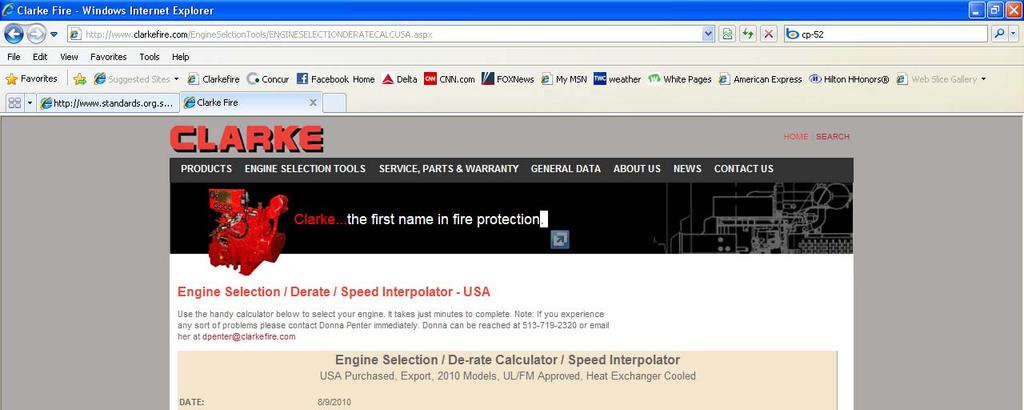

9 Engine Selection/De-rate Calculator

10 Engine Selection/De-rate Calculator
11 NFPA 20 Instrument & Control Engines shall be regulated to have no more the 10% speed difference between shutoff and maximum load. (Defined as droop). Engines shall be provided with an over speed shutdown at 20% above rated engine speed with a manual reset. (Only over speed shutdown or a signal from the diesel controller will shut down an engine.)
12 Over speed Setting Verification To verify the engine over speed setting and function without over speeding the engine, follow this procedure: Start engine manually from the controller while holding the over speed verification switch in the up position. Observe the shutdown RPM. Test switch returns to normal position when released. Reset the over speed switch on the engine instrument panel and restart the engine from the controller to verity normal operation. EXAMPLE: Rated engine speed: Over speed setting: Verification shutdown: 2100 rpm 2520 rpm (120% 2100 rpm) 1688 rpm (67% of 2520 rpm)

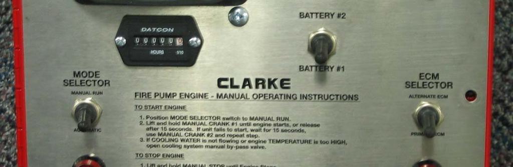
13 JU and JW Series Instrument Panel
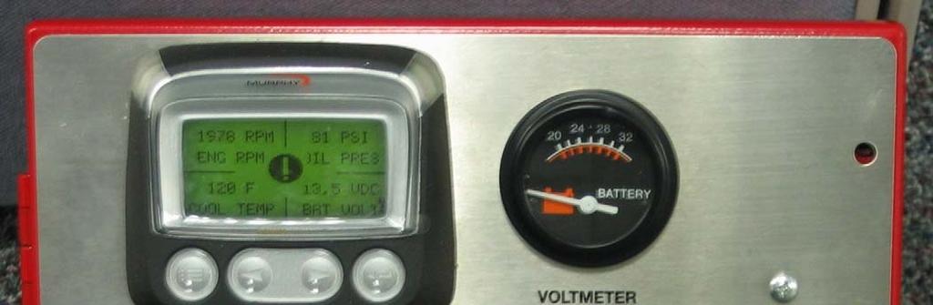
14 NFPA 20 Instrumentation & Control Required Gauges: Tachometer indicates rpms Oil Pressure Gauge Coolant Temperature Gauge Hour meter record engine run time Additional Gauges: Two voltmeters one for each set of batteries
15 NFPA 20 Instrumentation & Control The engine instrument panel shall not be used as a junction box or conduit for any ac supply. Interconnections between the automatic controller and engine junction box shall be made using stranded wire sized on a continuous-duty basis. The dc interconnections between the automatic controller and engine junction box and any ac power supply to the engine shall be routed in separate conduit.
16 Engine-to-Controller Connections Terminal Interconnect Function W Cooling Solenoid (only on mechanical and JX 12.5L) 1 Signal from Controller Energize to Run 2 Signal to Controller Engine Running 3 Signal to Controller Over Speed Alarm 4 Signal to Controller Low Oil Pressure Alarm 5 Signal to Controller High Engine Coolant Temp. Alarm 6 Power Supply and Charging Set #1 8 Power Supply and Charging Set #2 9 Cranking Signal from Controller Start System #1 10 Cranking Signal from Controller Start System #2 11 Common Ground 301 Signal to Controller Alternate ECM Alarm (electronic engines) 302 Signal to Controller General Fault Alarm(electronic engines) Typical Wire Size ** **Refer to Controller Manufacturer s Installation Instructions for minimum size recommendations. # W, 1-5, 9, 10, 301, Gauge (2 mm) Stranded Wire #6, 8, 11, 10 Gauge (5 mm) Stranded Wire
17 NFPA 20 Instrumentation & Control Engines with only one starting motor shall include a main battery contactor installed between each battery and the cranking motor for battery isolation. The battery contactors shall be listed for the service. Engines with two cranking motors shall have one cranking motor dedicated to each battery. Clarke electric starting standard; One (1) starter on JW6H, JX6H units. Two (2) starters on JU4H, JU6H units.

18
19 NFPA 20 Instrumentation & Control Electronic Engines Engines with an electronic control module (ECM) shall have an alternate ECM wired to produce full power in the event of primary ECM failure. There shall be a single ECM Selector Switch, with no off position, to transition from the primary ECM to the alternate ECM. A visual indicator shall show when the engine is running with the alternate ECM. (On both the engine panel and on the diesel controller)

20 JX Series Instrument Panel

21

22
23 NFPA 20 Instrumentation & Control Electronic Engines Any sensor necessary for the function of the ECM shall have a redundant sensor that shall operate automatically in case of failure. A signal shall be provided to the diesel controller for fuel injector failure, low fuel pressure and any primary sensor failure. New for The transition from the primary ECM to the alternate ECM shall be accomplished automatically upon failure of the primary ECM
24 NFPA 20 Instrumentation & Control Each engine shall be provided with two storage battery units. Electrolyte shall be added a minimum of 24 hours prior to the time the engine has to be started. At 4.5 C(40 F ) each battery shall have twice the capacity sufficient to maintain 3 minute attemptto-start cycle (15 seconds of cranking and 15 seconds of rest in six consecutive cycles). New for Batteries shall be sized on a calculated capacity of 72 hours of stand by power with out AC power being available
25 NFPA 20 Instrumentation & Control Storage batteries shall be rack supported above the floor to prevent water damage. Storage batteries shall be readily accessible for servicing. Storage batteries shall not be located in front of the engine mounted instruments and controls.
26 NFPA 20 Instrumentation & Control There should be two means for recharging the storage batteries. The battery chargers in the diesel controller is the primary source. The alternator on the engine is the secondary source.
27 NFPA 20 Connecting to Pump Engines shall be connected to horizontal shaft pumps by means of a flexible coupling or flexible connecting shaft (drive shaft) listed for this service. The flexible coupling shall be directly attached to the engine flywheel adapter or stub shaft.
28 NFPA 20 Engine Cooling The engine cooling system shall be of the closedcircuit type. Heat exchanger type Radiator type
29 NFPA 20 Engine Cooling Cooling water shall be piped through a threaded rigid pipe from the discharge of the pump to the inlet of the heat exchanger. It is not permitted to use flexible tubing attached to the cooling loop.
30 NFPA 20 Engine Cooling The outlet for the wastewater coming from the heat exchanger shall be one size larger then the inlet. The wastewater shall be discharged into a visible open waste cone. Discharge can be piped to a suction reservoir provided a visual flow indicator and temperature indicators are installed.
31 NFPA 20 Engine Cooling Heat exchanger standard equipment. Sea water or fresh water; sacrificial anode optional. Engines are shipped without coolant. Cooling water line (cooling loop) shall have a manual by-pass. Cooling water line and by-pass shall include: indicating manual shutoff valve approved flushing-type strainer pressure regulator automatic valve second indicating manual valve or check valve pressure gauge
32 Cooling Water Line
33 Engine Coolant Coolant is now included with the engine. Water, ethylene glycol, inhibitor coolant mixture. 50% water 50% coolant. Coolant to conform to ASTM D6210 or D4985 with SCA s. Heat transfer Corrosion resistance Prevents cavitation Prevents scale and sludge build up Provides freeze and boil over protection Pre-mix before installing in engine to prevent premature engine heater failure.
34 NFPA 20 Engine Cooling Coolant heater is the only AC power on engine; Separate AC junction box required. Do not use controller AC for power supply. Add coolant mixture before applying AC power. All heaters single voltage; Optional AC voltages available - location specific. Engine coolant maintained at 49 C (120 F ).
35 NFPA 20 Engine Protection The engine shall be protected against possible interruption of service through explosion, fire, flood, earthquake, rodents, insects, windstorm, freezing, vandalism and other adverse conditions. Application: The engine must be installed inside or protected from the weather and low temperature.
36 NFPA 20 Room Requirements Floors shall be pitched for adequate drainage of escaping water from critical equipment. The pump room shall be provided with a floor drain that will discharge to a frost free location. Fire pump rooms enclosing a diesel engine pump driver and day tank shall be protected with an automatic sprinkler system installed in accordance with NFPA 13. Emergency lighting shall be provided in accordance with NFPA 101. Emergency lights shall not be connected to an engine starting battery
37 NFPA 20 Room Requirements Rooms containing fire pumps shall be free from storage & penetrations not essential to the operation of the pump. New for Equipment related to domestic water distribution shall be permitted to be located within the same room as fire pump equipment. New for Room needs to be protected from surrounding occupancies by a minimum of 2 hour fire rated construction or physically separated from the building by 50 ft (15.3m) away from any buildings and other fire exposures exposing the building.
38 NFPA 20 Room Requirements New for 2010 Access to the fire pump room shall be pre-planned with the fire department New for Fire pump rooms not directly accessible from the outside shall be accessible through an enclosed passageway from an enclosed stairway or exterior exit. The enclosed passageway shall have a minimum 2 hour fire resistance rating.
39 NFPA 20 Air Requirements The minimum ambient temperature for the pump room is 4.5 C(40 F ). An approved or listed source of heat shall be provided for maintaining the temperature of a pump room or pump house. The maximum temperature for the pump room is 49 C (120 F ) at the air cleaner inlet with the engine running at rated load.
40 NFPA 20 Air Requirements Inlet louver and ventilating system must: Maintain 49 C (120 F ) in the room Supply adequate air for engine combustion Adequate air for ventilating radiated heat; both engine & exhaust system. (Radiator Cooled Units shall be ducted outdoors in a manner that will prevent recirculation and requires more air for combustion and radiated heat removal.)
41 Installation and Operation Data
42 Installation and Operation Data
43 Heat Exchanger Ventilation
44 Radiator Ventilation
45 Radiator Ventilation
46 Radiator Ventilation
47 NFPA 20 Fuel Tank Arrangement The fuel tank is sized for 5.07 liter/kw (1 gal/hp) plus 10% (5% for expansion and 5% for sump). The fuel tank shall be reserved exclusively for the fire pump diesel engine. There shall be one fuel tank per engine.
48 NFPA 20 Fuel Tank Arrangement The fuel tank shall be located above ground. The fuel tank outlet shall be located so that its opening is no lower than the level of the engine s fuel transfer pump. The static head pressure limits shall not be exceeded when the level of fuel in the tank is at a maximum. In sites where temperatures below 0 C(32 F ) could be encountered, the fuel tank shall be located in the pump room.
49 Installation and Operation Data
50 NFPA 20 Fuel Arrangement The diesel engine must use clean #2 diesel. #1, blended fuel, or jet fuel have a lower cetane ratings, which reduces the power output by 10% of the engine compared with the listed power. New for 2010 Biodiesel and other alternative fuels are not recommended for diesel engines used for fire protection because of the unknown storage life issues. A guard, pipe protection, or approved double walled pipe shall be provided for all exposed fuel lines.
51
52 NFPA 20 Fuel Arrangement Flame-resistant reinforced flexible hose shall be provided at the engine for connection to the fuel system piping. Fuel piping shall not be galvanized steel or copper. There shall be no shut-off in the fuel return line to the tank. The grade of fuel oil shall be indicated on the fuel tank by letters that are a minimum of 152mm (6 in) in height and in contrasting color to the tank.
53 NFPA 20 Engine Exhaust Each engine shall have an independent exhaust system. A flex connector shall be used between the engine and the exhaust pipe. The flex connector shall not be used for misalignment. (The purpose of the flex is to allow for thermal expansion and for isolating engine vibration from the rest of the exhaust system.)
54 NFPA 20 Engine Exhaust Back pressure in the exhaust system shall not exceed the engine s limit. The exhaust sizing program on the Clarke website can calculate the back pressure) Building supported; not engine supported Insulation wrap the exhaust systems in-room components. Rain cap on outlet if necessary; tight connections. Exhaust system shall terminate outside where hot gases and sparks are discharged to a safe location.

55 Exhaust Sizing

56 Exhaust Sizing

57 Exhaust Sizing

58 Exhaust Sizing
59 NFPA 20 System Operation Engines shall be started no less than once a week and run for no less than 30 minutes. The fire pump shall be started and brought up to rated speed without interruption within 20 seconds.
60 NFPA 20 System Operation Batteries shall be kept charged at all times and tested frequently (weekly test) to determine condition. Only distilled water shall be used. Battery plates shall be kept submerged at all times. The fuel storage tanks shall be kept as full as practical at all times, but never below 66% of tank capacity. A fuel level indicator shall be provided to activate at the 2/3rds tank level.
61 2009 EMISSION SUMMARY Beginning Jan 1, 2010 Diesel Fire Pump drivers with horsepowers between 100 bhp and 750 bhp and with rpms between 1470 and 2650 rpm must meet be certified Tier 3 engines. NSPS compliant engines manufactured before Jan 1, 2010 in the above horsepower and rpm range can still be sold in 2009.
62 Clarke Model Nomenclature
63 UL Coupling for Electric Motors Separately coupled-type pumps with electric motor drivers shall be connected by a flexible coupling or flexible connecting shaft. All coupling types shall be listed for the service. This requirement has actually been around since the 1996 edition of NFPA 20. Currently Clarke is the only company that has a UL coupling available for electric motors.
64 Clarke Website Current Models Installation & Operation Data Emission Data Exhaust Sizing Operations Manual Spare Parts Illustration Installation Checklist Power Curves Installation Drawings Contact List Wiring Diagrams Technical Manual Service Dealer Directory Startup and Warranty Forms
NMSU FIRE DEPARTMENT FIRE PUMP ACCEPTANCE TEST
 Date Documents Submitted: Log No.: File No.: Plan Examiner: Permit No.: Property Information Building Name: Building Address: Building Manager's Name: Building Manager's Phone: Fax: System Designer/Contractor
PRESSURE LIMITING DRIVERS
 PLD Models for Discharge & Suction Pressure Limiting Control FM-UL-cUL APPROVED RATINGS BHP/kW Certified Models NSPS Emissions Tier Engine Fuel Management Control Discharge Control Limiting Pressure (psi)
.3 Section Concrete Forms and Accessories: Installation of Anchor Devices, Setting Templates
 Issued 2005/06/01 Section 16239 Power Generation to 30 kw Page 1 of 7 PART 1 GENERAL 1.1 RELATED WORK.1 Section 01355 Waste Management and Disposal..2 Section 01810 Commissioning..3 Section 03100 Concrete
MODELS KA4H-UFKA24. FM-UL-cUL APPROVED RATINGS KW/BHP SPECIFICATIONS KA4H MODELS FIRE PUMP ENGINES RATED SPEED KA4H MODEL UFKA24 ITEM
 MODELS KA4H-UFKA24 FIRE PUMP ENGINES FM-UL-cUL APPROVED RATINGS KW/BHP KA4H MODEL RATED SPEED 2800 3000 KA4H-UFKA24 45 34 45 34 = Non-Emissionized SPECIFICATIONS KA4H MODELS ITEM UFKA24 Number of Cylinders
MOBILE FIRE - RESCUE DEPARTMENT FIRE CODE ADMINISTRATION
 MOBILE FIRE - RESCUE DEPARTMENT FIRE CODE ADMINISTRATION Fire Pump Acceptance Inspection Date of Review / / BLD20 - Project Address: Project Name: Numbers following worksheet comments represent an NFPA
PRESSURE LIMITING DRIVERS
 PLD Models for Discharge & Suction Pressure Limiting Control FM-UL-cUL APPROVED RATINGS BHP/kW Certified Models NSPS Emissions Tier Engine Fuel Management Control Discharge Control Limiting Pressure (psi)
Table Summary of Sprinkler System Inspection, Testing, and Maintenance. Reference. Inspection , ,
 Table 5.1.1.2 Summary of Sprinkler System Inspection, Testing, and Maintenance Item Frequency Reference Inspection Gauges (dry, preaction, and deluge systems) Quarterly 5.2.4.2, 5.2.4.3, 5.2.4.4 Control
Application & Reference Data Typical Specifications. Section 914 Vertical Turbine Fire Pump
 Section 914 Page 101 Supersedes Section 913 Page 101 Dated November 1, 199p Application & Reference Data Typical Specifications Section 914 Section 914 Page 102 Supersedes Section 913 Page 102 Dated November
(NSPS) Available until
 Available until") FIRE PUMP ENGINES JW6H-UFADF0 JW6H-UFADJ0 JW6H-UFAD70 MODELS JW6H-UFAD80 JW6H-UFAA60 JW6H-UFAA80 FM-UL-cUL APPROVED RATINGS BHP/KW JW6H MODEL RATED SPEED 1760 1900 2100 2350 US-EPA (NSPS) Available until
FIRE PUMP ENGINES JW6H-UFADF0 JW6H-UFADJ0 JW6H-UFAD70 MODELS JW6H-UFAD80 JW6H-UFAA60 JW6H-UFAA80 FM-UL-cUL APPROVED RATINGS BHP/KW JW6H MODEL RATED SPEED 1760 1900 2100 2350 US-EPA (NSPS) Available until
Section 3 Technical Information
 Section 3 Technical Information In this Module: Engine identification Modes of operation Battery charging and heat manage operation Service and repair procedures Maintenance requirements Engine Identification
Standby Power Systems
 Source: Power Quality in Electrical Systems Chapter 13 Standby Power Systems The term standby power systems describes the equipment interposed between the utility power source and the electrical load to
AIR COOLED CHILLERS WATER COOLED CHILLERS
 AIR COOLED CHILLERS WATER COOLED CHILLERS STANDARD UNIT SPECIFICATIONS OF COMMERCIAL AIR COOLED CHILLERS General Description & Assembly Air Cooled Chillers are commercial packaged systems complete with
FIRE PROTECTION PUMPS. Table of Contents
 FM Global Property Loss Prevention Data Sheets 3-7 April 2012 Page 1 of 45 FIRE PROTECTION PUMPS Table of Contents Page 1.0 SCOPE... 3 1.1 Changes... 3 2.0 LOSS PREVENTION RECOMMENDATIONS... 3 2.1 Introduction...
Fire Pumps Inspection, testing and maintenance of fire pumps
 FIRE SYSTEMS BY WALTER S. BEATTIE, CSP, CFPS, CSHM Fire Pumps Inspection, testing and maintenance of fire pumps are critical to fire safety. Fire pumps help supply hydrants and sprinkler systems with the
SeasonPak Packaged Air-Cooled Water Chiller
 Installation Manual IM 676 Group: Chiller Part Number: 594920Y Date: July 1996 Supersedes: None SeasonPak Packaged Air-Cooled Water Chiller Models ALR 032E Through 185E 1996 McQuay International Table
Bombardier Challenger Auxiliary Power Unit
 GENERAL A Honeywell 36 150(CL) constant-speed gas turbine auxiliary power unit (APU) is installed within a fire-resistant compartment in the aft equipment bay. The APU drives a generator, providing AC
FIRE PUMP MODEL: JW6H-UF50 Heat Exchanger Cooled RE Turbocharger Raw Water Charge Cooling ENGINE SPEED - RPM
 380 FIRE PUMP MODEL: JW6H-UF50 Heat Exchanger Cooled RE505257 Turbocharger Raw Water Charge Cooling 360 350 (261) 340 340 (254) 320 300 300 (224) 280 260 1700 1800 1900 2000 2100 2200 2300 RESTRICTED:
Direct Gas-Fired Heating
 Direct Gas-Fired Heating Model DG 800 to 15,000 cfm Up to 1,600,000 BTU/hr Optional Evaporative Cooling January 2005 PRODUCT FEATURES Model DG Direct Gas-Fired Make-Up Air Unit The Greenheck model DG is
UK Purchased. TRWA Rotation* 929 (2053) Compression Ratio. 15.7:1 Displacement l (cu. in.)
 Compression Ratio. 15.7:1 Displacement l (cu. in.)") MODELS FIRE PUMP ENGINES JW6H-AP30 JW6H-AP40 JW6H-AP50 JW6H-AP60 UK Purchased APSAD ENGINE MODELS GROSS POWER RATINGS KW/BHP JW6H MODEL AP30 AP40 AP50 AP60 217 238 246 295 1760 291 319 330 396 218 239
MODELS FIRE PUMP ENGINES JW6H-AP30 JW6H-AP40 JW6H-AP50 JW6H-AP60 UK Purchased APSAD ENGINE MODELS GROSS POWER RATINGS KW/BHP JW6H MODEL AP30 AP40 AP50 AP60 217 238 246 295 1760 291 319 330 396 218 239
Inspection, Testing, and Maintenance Fire Pumps NFPA 25, Chapter 8 as amended by CCR, Title 19 Page 1 of 8
 , Chapter 8 as amended by CCR, Title 19 Page 1 of 8 Address: City: Date of Pump Test: Shaft Orientation: Horizontal Vertical Annual Fire Pump Test Results Number of pumps at this location: If multiple
M-SERIES MHP4 MODEL NUMBER GUIDE 3 M HP F P 1 ELECTRIC HEAT PUMP PACKAGED UNITS REVISION CODE
 ELECTRIC HEAT PUMP PACKAGED UNITS MHP4 FORM NO. MHP4-100 (10/2018) MODEL NUMBER GUIDE 3 M HP 4 11 18 1 F P 1 FACTORY INSTALLED ELECTRIC HEAT 3= 3 KW 5 = 5 KW 7 = 7 KW 10 = 10 KW M = MAGIC-PAK HP = HEAT
The Premium Quality Fan Coil Units for Horizontal Application Hydronic or Electric Heat
 Producing Quality Heating & Cooling Equipment For Over 50 Years CEA SERIES CEILING EPOSED HORIZONTAL FAN COIL UNITS The Premium Quality Fan Coil Units for Horizontal Application Hydronic or Electric Heat
(800)
") Industrial Diesel Incorporated TECHNICAL SPECIFICATION 1000 HP Acid Pumper (Unit # 1345) 11000000 H HO OR RS SE EP PO OW WE ER RH HIIG GH HP PR RE ES SS SU UR RE EP PU UM MP P TTR RA AIILLE ER R TRAILER
Industrial Diesel Incorporated TECHNICAL SPECIFICATION 1000 HP Acid Pumper (Unit # 1345) 11000000 H HO OR RS SE EP PO OW WE ER RH HIIG GH HP PR RE ES SS SU UR RE EP PU UM MP P TTR RA AIILLE ER R TRAILER
Twin City Fan & Blower
 BULLETIN 600 Twin City Fan & Blower September 2009 VENTILATING SETS TYPE BCV (Backward Inclined) TYPE BCVU5 (UL 705 Listed) TYPE BCVU2 (UL 762 Listed) TYPE BCVSH (UL Smoke & Heat) TYPE BAV (Airfoil) TYPE
Utility Sets Standard Design Features Standard design features common to all Class I and Class II fans
 Standard Design Features Utility Sets Standard Design Features Standard design features common to all Class I and Class II fans Shaft AISI 1045, turned ground and polished for accuracy. Designed to provide
University of Houston Master Construction Specifications Insert Project Name
 SECTION 23 30 00 - HVAC PUMPS PART 1 - GENERAL 1.1 RELATED DOCUMENTS: A. The Conditions of the Contract and applicable requirements of Division 1, "General Requirements", and Section 23 01 00, "Mechanical
UTILITY BLOWERS. Models: BIUB / BIUBR / BIUBSH BAUB / DFC / FCUB. The Industrial Choice.
 UTILITY BLOWERS Models: BIUB / BIUBR / BIUBSH BAUB / DFC / FCUB The Industrial Choice. CATALOG 760 April 2017 Utility Blowers Overview Utility Blowers Aerovent s line of utility blowers is one of the most
Air Moving Solutions. VENTILATING SETs BCV BCVU5 BCVU2 BCVSH BAV FCV
 Air Moving Solutions. VENTILATING SETs BCV BCVU5 BCVU2 BCVSH BAV FCV CATALOG 600 March 2012 VentilatingSets Models BCV BCVU5 BCVU2 BCVSH BAV FCV Twin City Fan s line of utility ventilating sets is one
Q= C. v P S Refer to Table 1 for part numbers and shipping weights. Accessories: Table 1: Valve Part Numbers and Specifications
 1 of 9 1. DESCRIPTION The Viking Flow Control Valve is a quick opening, differential diaphragm flood valve with a spring loaded floating clapper. The Flow Control Valve can be used to facilitate manual
C18 ACERT Fire Pump Tier bkw/ rpm
 CATERPILLAR ENGINE SPECIFICATIONS I-6, 4-Stroke-Cycle Diesel Bore...145.0 mm (5.71 in) Stroke...183.0 mm (7.2 in) Displacement... 18.1 L (1,104.53 in3) Aspiration...Turbocharged Aftercooled Compression
C18 ACERT Fire Pump Tier bkw/ rpm
 CATERPILLAR ENGINE SPECIFICATIONS I-6, 4-Stroke-Cycle Diesel Bore...145.0 mm (5.71 in) Stroke...183.0 mm (7.2 in) Displacement... 18.1 L (1,104.53 in3) Aspiration...Turbocharged Aftercooled Compression
C18 ACERT Fire Pump Tier bkw/ rpm
 CATERPILLAR ENGINE SPECIFICATIONS I-6, 4-Stroke-Cycle Diesel Bore...145.0 mm (5.71 in) Stroke...183.0 mm (7.2 in) Displacement... 18.1 L (1,104.53 in3) Aspiration...Turbocharged Aftercooled Compression
Light condition and operation Windshield glass condition Wiper blade condition Paint condition and corrosion Fluid leaks Door and hood lock condition
 GENERAL CHECKS Engine Compartment The following should be checked regularly: Engine oil level and condition Transmission fluid level and condition Brake fluid level Clutch fluid level Engine coolant level
C18 ACERT Fire Pump Tier bkw/ rpm
 CATERPILLAR ENGINE SPECIFICATIONS I-6, 4-Stroke-Cycle Diesel Bore...145.0 mm (5.71 in) Stroke...183.0 mm (7.2 in) Displacement... 18.1 L (1,104.53 in3) Aspiration...Turbocharged Aftercooled Compression
Clarke Fire Diesel Engine
 CLARKE FIRE DIESEL ENGINE PDF - Are you looking for clarke fire diesel engine Books? Now, you will be happy that at this time clarke fire diesel engine PDF is available at our online library. With our
DG175 GC to DG450 GC GAS GENERATOR SETS
 DG175 GC to DG450 GC GAS GENERATOR SETS The Cat Spark-Ignited Generator Product Line For Stationary Applications 175-450 ekw, 60 Hz G14.2L and G21.9L spark-ignited engines OUR PROMISE. YOUR POSSIBILITY.
of Fire Pump Assemblies
 A.1.0 A.1.1 A.2.0 A.2.1 A.2.2 A.2.3 A.2.4 A.2.5 A.2.6 A.3.0 A.3.1 A.4.0 A.4.1 Report of Inspection, Testing & Maintenance System in service before conducting tasks Pertinent parties notified before conducting
Recold JW Series. Lenntech. Tel Fax ENGINEERING DATA AND SPECIFICATIONS
 Lenntech info@lenntech.com Tel. +31-152-610-900 www.lenntech.com Fax. +31-152-616-289 ENGINEERING DATA AND SPECIFICATIONS Recold JW Series FLUI D COOLER Recold JW Series Fluid Cooler Contents 2 Construction...
NFPA , Standard for the Inspection, Testing, and Maintenance of Water-Based Fire Protection Systems REVIEW SUMMARY
 NFPA 25-2017, Standard for the Inspection, Testing, and Maintenance of Water-Based Fire Protection Systems REVIEW SUMMARY 1) NFPA 25 REVISION SUMMARY For the 2017 edition, new fire pump terms are defined
Fortress 1 Outdoor Emergency Central Lighting Inverter (CLI) Technical Specifications
 Technical Specifications") Fortress 1 Outdoor Emergency Central Lighting Inverter (CLI) Technical Specifications PART 1 GENERAL 1.1 SUMMARY A. This specification describes a single phase, on-line, double conversion, solid state
Fortress 1 Outdoor Emergency Central Lighting Inverter (CLI) Technical Specifications PART 1 GENERAL 1.1 SUMMARY A. This specification describes a single phase, on-line, double conversion, solid state
(NSPS) Available Until
 Available Until") FIRE PUMP ENGINES MODELS JU6H-UFADMG JU6H-UFADP0 JU6H-UFADR0 JU6H-UFADT0 JU6H-UFAD58 JU6H-UFADP8 JU6H-UFADR8 JU6H-UFADW8 JU6H-UFADNG JU6H-UFADQ0 JU6H-UFADS8 JU6H-UFADX8 JU6H-UFADM8 JU6H-UFADN0 JU6H-UFAD88
FIRE PUMP ENGINES MODELS JU6H-UFADMG JU6H-UFADP0 JU6H-UFADR0 JU6H-UFADT0 JU6H-UFAD58 JU6H-UFADP8 JU6H-UFADR8 JU6H-UFADW8 JU6H-UFADNG JU6H-UFADQ0 JU6H-UFADS8 JU6H-UFADX8 JU6H-UFADM8 JU6H-UFADN0 JU6H-UFAD88
Secondary Coolant 301
 Secondary Coolant 301 Instructor Rusty Walker Hill PHOENIX Learning Center Secondary Coolant 301 Start-Up Procedures Secondary Coolant 301 Objectives Describe the initial startup procedures for a medium
Operation and Maintenance Manual Doc. A042J563 April 2017 English Version
 Fire Pump Drive Engines CFP5E Series Operation and Maintenance Manual Doc. A04J563 April 07 English Version This manual contains proprietary information to equipment produced by Cummins Inc. and is being
Air-Cooled Screw Compressor Chiller
 Installation, Operation and Maintenance Manual IOMM ALS Group: Chiller Part Number: 070774401 Date: February 1998 Supersedes: IM 548-3 Air-Cooled Screw Compressor Chiller ALS 070A through 425A 60 Hertz
PACKAGED LIQUID CHILLER 6. HUMIDIFIER SECTIONS. C Member. Liquid Chiller. nowlc And noalc Series
 6. HUMIDIFIER SECTIONS Liquid Chiller nowlc And noalc Series C Member 1 Features and Benefits OMRAN cold generator reciprocating Liquid chiller are designed and built to provide reliable,efficient performance
SECTION HVAC POWER VENTILATORS
 SECTION 233423 HVAC POWER VENTILATORS 1. PART 1 GENERAL 1.1. RELATED DOCUMENTS A. Drawings and general provisions of the Contract, including General and Supplementary Conditions and Division 01 Specification
Generator Set Configurations Low Fuel Consumption, EU Stage IIIA Nonroad Emission Standards, China Nonroad III Emission Standards
 Caterpillar is leading the power generation marketplace with Power Solutions engineered to deliver unmatched flexibility, expandability, reliability, and cost-effectiveness. Specifications Generator Set
ENGINE EQUIPMENT. For DC Wiring Interconnection To Alternator (S) 24V-DC, 40 Ampere, Engine Controller with Belt Guard
 24V-DC, 40 Ampere, Engine Controller with Belt Guard") CLARKE FIRE PUMP DRIVERS MODELS DDFP-08FH DDFP-08FA DDFP-12FH APPROVED RATINGS BHP/kw FM-UL-ULC* SPEED (RPM) MODEL 1470 1760 2100 2350 DDFP- 420 509 552 570 08FA 313 380 412 425 DDFP- 468 575 669 708 08FH
CLARKE FIRE PUMP DRIVERS MODELS DDFP-08FH DDFP-08FA DDFP-12FH APPROVED RATINGS BHP/kw FM-UL-ULC* SPEED (RPM) MODEL 1470 1760 2100 2350 DDFP- 420 509 552 570 08FA 313 380 412 425 DDFP- 468 575 669 708 08FH
CHAPTER 20: Operation and maintenance
 Pressurized Irrigation Techniques 20.1 CHAPTER 20: Operation and maintenance INTRODUCTION The efficient operation of an irrigation system depends mainly on the ability of the farmer to make the best use
PRIME 220 ekw 275 kva 50 Hz 1500 rpm 415 Volts
 Designed to match performance and output characteristics of Caterpillar diesel engines Two-thirds pitch minimizes harmonic distortion and facilitates parallel operation DIESEL GENERATOR SET PRIME 220 ekw
FM-UL-cUL APPROVED RATINGS BHP/KW SPECIFICATIONS JU6H MODELS ITEM FIRE PUMP ENGINES JU6H MODEL (NSPS) Available Until
 Available Until") FIRE PUMP ENGINES MODELS JU6H-UFADMG JU6H-UFADP0 JU6H-UFADR0 JU6H-UFADT0 JU6H-UFAD58 JU6H-UFADP8 JU6H-UFADR8 JU6H-UFADW8 JU6H-UFADNG JU6H-UFADQ0 JU6H-UFADS8 JU6H-UFADX8 JU6H-UFADN0 JU6H-UFAD88 JU6H-UFADS0
FIRE PUMP ENGINES MODELS JU6H-UFADMG JU6H-UFADP0 JU6H-UFADR0 JU6H-UFADT0 JU6H-UFAD58 JU6H-UFADP8 JU6H-UFADR8 JU6H-UFADW8 JU6H-UFADNG JU6H-UFADQ0 JU6H-UFADS8 JU6H-UFADX8 JU6H-UFADN0 JU6H-UFAD88 JU6H-UFADS0
Unit D: Agricultural Equipment Systems. Lesson 1: Understanding Applications of Fluids and Lubricants in Agricultural Equipment
 Unit D: Agricultural Equipment Systems Lesson 1: Understanding Applications of Fluids and Lubricants in Agricultural Equipment 1 Terms Ash content bottom dead center cloud point compression ratio coolant
SECTION U -- STANDBY ENGINE/ALTERNATOR SETS
 SECTION U -- STANDBY ENGINE/ALTERNATOR SETS CONTENTS PAGE 1. GENERAL... U-1 1.1. Introduction... U-1 2. REQUIREMENTS... U-2 2.1. General... U-2 2.2. Exhaust Requirements... U-2 2.3. Alarms... U-2 2.4.
Advantage-D. Operating Instructions and Maintenance Manual. Central Vacuum Systems (Expandable/Modular Models) (Ver.
 (Ver.") Advantage-D Series 3 Central Vacuum Systems (Expandable/Modular Models) (Ver. 8/05) Operating Instructions and Maintenance Manual DESCRIPTION The Becker Advantage-D and Advantage-L central vacuum systems
Advantage-D Series 3 Central Vacuum Systems (Expandable/Modular Models) (Ver. 8/05) Operating Instructions and Maintenance Manual DESCRIPTION The Becker Advantage-D and Advantage-L central vacuum systems
Start-Up and Installation Checklist
 DEUTZ Fire Protection Start-Up and Installation Checklist Return Completed Form To: DEUTZ Fire Protection Warranty Administration Department 3883 Steve Reynolds Boulevard, Norcross, GA 30093 Phone 1-800-241-9886
TECHNICAL DATA. Q= C v P S
 1 of 9 1. DESCRIPTION The Viking Model E-1 Deluge Valve is a quick-opening, differential diaphragm, flood valve with one moving part. The deluge valve is used to control water flow in deluge and preaction
GENCORE 5 FUEL CELL SYSTEM System Fundamentals
 GENCORE 5 FUEL CELL SYSTEM System Fundamentals GenCore 5T48 GenCore 5B48 GenCore 5U48 GenCore 5T24 GenCore 5U120 Revision 1 December 1, 2004 GENCORE DESCRIPTION GenCore fuel cell systems are direct hydrogen
TECHNICAL DATA. Q= C v P Cv = Flow Factor (GPM/1 PSI P)
") 1 of 9 1. DESCRIPTION The Viking 2 (DN50) is a quick-opening, differential diaphragm, flood valve with one moving part. The deluge valve is used to control water flow in deluge and preaction sprinkler
1 of 9 1. DESCRIPTION The Viking 2 (DN50) is a quick-opening, differential diaphragm, flood valve with one moving part. The deluge valve is used to control water flow in deluge and preaction sprinkler
SECTION CENTRIFUGAL HVAC FANS
 SECTION 233416 - CENTRIFUGAL HVAC FANS 1. PART 1 GENERAL 1.1. RELATED DOCUMENTS A. Drawings and general provisions of the Contract, including General and Supplementary Conditions and Division 01 Specification
STEP-BY-STEP INSTALLATION GUIDE
 Battery Backup System STEP-BY-STEP INSTALLATION GUIDE Operating Instructions & Parts Manual ESP25 Please read and save these instructions. Read carefully before attempting to assemble, install, operate
R-22, 13 SEER 60 Hertz
 TECHNICAL GUIDE R-22, 13 SEER 60 Hertz Description These UPG packaged cooling/heating air conditioners are designed for outdoor installation. Only utility and duct connections are required at the point
Doosan XHP1170FCAT Bid Specifications
 MANUFACTURER MODEL Doosan Infracore XHP1170FCAT ENGINE TIER 3 Make CATERPILLAR Model C-15 Number of Cylinders 6 Cylinder Bore (in/mm) 5.4 (137) Cylinder Stroke (in/mm) 6.73 (15.2) Displacement (cu in/l)
AS Electric Fire Pumpset Check List Please answer YES or No as appropriate. (if the answer is "NOT SURE" then answer "NO!
 AS 2941-2013 Electric Fire Pumpset Check List Please answer YES or No as appropriate. (if the answer is "NOT SURE" then answer "NO!" Clause ITEMS TO CHECK INSPECTION REPORT Complies Electric Motor Driven
SECTION 3.00 WARNING WARNING ENGINE STARTUP AND SHUTDOWN PRESTART INSPECTION
 SECTION 3.00 ENGINE STARTUP AND SHUTDOWN PRESTART INSPECTION Be sure that the clutch, circuit breaker, or other main power transmission device is disconnected. Generators develop voltage as soon as the
CLARKE FIRE PUMP DRIVERS. approved MODELS. meets NFPA-20 Requirements VMFP-04HN VMFP-04HT VMFP-06HT VMFP-T6HT VMFP-L6HR VMFP-T6HR
 CLARKE FIRE PUMP DRIVERS MODELS VMFP-04HN VMFP-04HT VMFP-06HT VMFP-T6HT VMFP-L6HR VMFP-T6HR APPROVED RATINGS (BHP)/(kw) FM-UL* VMFP MODEL 04HN 04HT 06HT T6HT L6HR T6HR OPERATING SPEED (RPM) 2800 3000 3300
BSS Examination Record Form for Privately Owned and Managed Vessels
 BSS Examination Record Form for Privately Owned and Managed Vessels [Edition 1.04 April 2013] Current boat name Former name Reg. number or index Length (m) Berths Hull material Hull colour Superstructure
(800)
") TECHNICAL SPECIFICATION BJ GORILLA 3000-T 3000 HORSE POWER FRACTURING PUMP TEST UNIT (GOOD USED) INTRODUCTION: This specification covers the minimum requirements of the Trailer Mounted Fracturing Pump
TECHNICAL SPECIFICATION BJ GORILLA 3000-T 3000 HORSE POWER FRACTURING PUMP TEST UNIT (GOOD USED) INTRODUCTION: This specification covers the minimum requirements of the Trailer Mounted Fracturing Pump
CONTINUOUS 800 ekw 1000 kva 50 Hz 1500 rpm 400 Volts
 IE DIESEL FEATURES GENERATOR SET CONTINUOUS 800 ekw 1000 kva Image shown may not reflect actual package Caterpillar is leading the power generation Market place with Power Solutions engineered to deliver
Heat Transfer in Engines. Internal Combustion Engines
 Heat Transfer in Engines Internal Combustion Engines Energy Distribution Removing heat is critical in keeping an engine and lubricant from thermal failure Amount of energy available for use: Brake thermal
Generator Fire Safety: Generator assemblies should be located outside the building.
 SECTION 33 70 00 - ELECTRICAL DISTRIBUTION PACKAGED GENERATOR ASSEMBLIES Generator Fire Safety: Generator assemblies should be located outside the building. All fuel piping from the outside of the building
SECTION PACKAGED ENGINE GENERATOR SYSTEMS
 PROJECT: SECTION 16620 PACKAGED ENGINE GENERATOR SYSTEMS PART 1 GENERAL 1.1 SUMMARY: A. This Section includes packaged engine-generator systems for emergency power supply with the following features: 1.
C280-8 MARINE PROPULSION
 C280-8 MARINE PROPULSION 3084 bhp (2300 bkw) 900 rpm SPECIFICATIONS Shown with Accessory Equipment In-Line 8, 4-Stroke-Cycle-Diesel Emissions.................. IMO/EPA Tier 2 Compliant Bore mm (in)...
Fortress 3 Harsh. Harsh Environment. Emergency Central Lighting Inverter (CLI) Technical Specifications
 Technical Specifications") Fortress 3 Harsh Emergency Central Lighting Inverter (CLI) Technical Specifications PART 1 GENERAL 1.1 SUMMARY A. This specification describes a three phase, on-line, double conversion, solid state Lighting
Fortress 3 Harsh Emergency Central Lighting Inverter (CLI) Technical Specifications PART 1 GENERAL 1.1 SUMMARY A. This specification describes a three phase, on-line, double conversion, solid state Lighting
STANDBY 650 ekw 812 kva 60 Hz 1800 rpm 480 Volts
 DIESEL GENERATOR SET Image shown may not reflect actual package. STANDBY 650 ekw 812 kva Caterpillar is leading the power generation marketplace with Power Solutions engineered to deliver unmatched flexibility,
Inspecting Airport Fueling Systems
 Inspecting Airport Fueling Systems 1 SECTION 139.321(d) Quarterly Fuel Inspections 139.321(d) Each certificate holder shall inspect the physical facilities of each airport tenant fueling agent at least
CMEC POWER GENERATION. PRIME 800 ekw 1000 kva 50 Hz 1500 rpm 400 Volts DIESEL GENERATOR SET WHERE THE WORLD TURNS FOR POWER FEATURES
 DIESEL GENERATOR SET FEATURES Image shown may not reflect actual package. FUEL/EMISSIONS STRATEGY Low fuel consumption SINGLE-SOURCE SUPPLIER Designed and built at Caterpillar ISO certified facilities
TECHNICAL DATA. Viking Technical Data may be found on Style: 90 Degree Pattern (inlet to outlet)
") Flow Control 500a DESCRIPTION The Viking 1-1/2 is a quick opening, differential type flood valve with a spring loaded rolling diaphragm clapper. The can be used to facilitate manual or automatic on/off
Flow Control 500a DESCRIPTION The Viking 1-1/2 is a quick opening, differential type flood valve with a spring loaded rolling diaphragm clapper. The can be used to facilitate manual or automatic on/off
PRESSURE LIMITING DRIVERS
 PLDTMFIRE PUMP ENGINES PRESSURE LIMITING DRIVERS SERIES JU4H JW6H JU6H JX6H PLD Models for Discharge & Suction Pressure Limiting Control FM-UL-cUL APPROVED RATINGS BHP/kW Certified Models NSPS Emissions
PRIME 3880 ekw 4850 kva 50 Hz 1000 rpm
 DIESEL GENERATOR SET PRIME 3880 ekw 4850 kva Image shown may not reflect actual package Caterpillar is leading the power generation Market place with Power Solutions engineered to deliver unmatched flexibility,
OutdoorXUPS-600AHV-8364
 OutdoorXUPS-600AHV-8364 TSi Power s OutdoorXUPS-600AHV-8364 provides secure and uninterrupted 230 vac power to critical loads. 1) Weather-tight metal cabinet (IP44 or NEMA 3R rated) 2) 2A and 2B are wide
CENTAXIAL TUBULAR CENTRIFUGAL FANS. BIA Airfoil Blade Design Direct Drive & Belt Driven Model CBD / CDD (Class I, II & III) Model CBD Belt Driven
 Model CBD Belt Driven") Model CBD Belt Driven Model CDD Direct Drive CENTAXIAL TUBULAR CENTRIFUGAL FANS BIA Airfoil Blade Design Direct Drive & Belt Driven Model CBD / CDD (Class I, II & III) CATALOG 337 February 2004 Centaxial
Model CBD Belt Driven Model CDD Direct Drive CENTAXIAL TUBULAR CENTRIFUGAL FANS BIA Airfoil Blade Design Direct Drive & Belt Driven Model CBD / CDD (Class I, II & III) CATALOG 337 February 2004 Centaxial
Doosan XHP1070WCAT Bid Specifications
 MANUFACTURER MODEL Doosan Infracore XHP1070WCAT ENGINE TIER 1 Make/model CATERPILLAR 3406TA Number of cylinders 6 Displacement 893 cid 14.6 L Bore and stroke 5.4 x 6.5 13.7cm x 16.5cm Speed idle / full
MerCruiser & Mercury Diesel Logbook R02
 MerCruiser & Mercury Diesel Logbook 90-889160R02 04/2015 IMPORTANT Maintenance must be completed by a Mercury Marine/Brunswick Marine in EMEA authorized dealer. At the completion of any maintenance check-up
1) Only gasoline exhaust systems shall be gas-tight to the hull interior
 Only gasoline exhaust systems shall be gas-tight to the hull interior") 1) Only gasoline exhaust systems shall be gas-tight to the hull interior 2) The primary purpose of an exhaust riser is to: a) direct laminar flow of exhaust gases overboard b) prevent water from flowing
1) Only gasoline exhaust systems shall be gas-tight to the hull interior 2) The primary purpose of an exhaust riser is to: a) direct laminar flow of exhaust gases overboard b) prevent water from flowing
STANDBY 2860 ekw 3575 kva 50 Hz 1000 rpm
 DIESEL GENERATOR SET STANDBY 2860 ekw 3575 kva Image shown may not reflect actual package Caterpillar is leading the power generation Market place with Power Solutions engineered to deliver unmatched flexibility,
VANEAXIAL & TUBEAXIAL FANS
 BULLETIN 482 July 2008 VANEAXIAL & TUBEAXIAL FANS Type "S" Belt Driven Featuring Welded Steel Propellers Models VSBD & TSBD Model TSBD Belt Driven Tubeaxial Type "S" Vaneaxial & Tubeaxial Fans For applications
CAS. Product Specifications. COMMERCIAL SPLIT SYSTEMS CONDENSING UNITS R 410A, 6 to 20 TONS BUILT TO LAST, EASY TO INSTALL AND SERVICE
 COMMERCIAL SPLIT SYSTEMS CONDENSING UNITS R 410A, 6 to 20 TONS BUILT TO LAST, EASY TO INSTALL AND SERVICE Single stage cooling capacity control on all 0 241 models Two stage cooling capacity control on
MSC Guidelines for Fuel Oil Systems
 P. W. Gooding, CDR, Chief, Engineering Division References: Contact Information: a. 46 CFR 56.50-60 Systems containing oil (Subchapter F) b. 46 CFR 56.50-65 Burner fuel-oil service systems (Subchapter
PCB COMMERCIAL SERIES
 PCB COMMERCIAL SERIES 50 Hz SELF-CONTAINED PACKAGE CONDITIONER 7½, 0, AND 5 TON [6.4 kw to 5.8 kw] COOLING CAPACITY: 90,000 TO 80,000 BTU/H The PCB Commercial 50 Hz self-contained packaged air conditioner
STANDBY 720 ekw 900 kva 50 Hz 1500 rpm 400 Volts
 DIESEL GENERATOR SET STANDBY 720 ekw 900 kva Caterpillar is leading the power generation marketplace with Power Solutions engineered to deliver unmatched flexibility, expandability, reliability, and cost-effectiveness.
TECHNICAL DATA 1-1/2 (dn40)
") July 1, 2011 Deluge Valves 209a DESCRIPTION The Viking Model E-3 1-1/2 Deluge Valve is a quick-opening, differential type flood valve with a rolling diaphragm clapper. The deluge valve is used to control
July 1, 2011 Deluge Valves 209a DESCRIPTION The Viking Model E-3 1-1/2 Deluge Valve is a quick-opening, differential type flood valve with a rolling diaphragm clapper. The deluge valve is used to control
Technical Data 1300 Series EDi 1306C-E87TAG4
 Technical Data 1300 Series EDi 1306C-E87TAG4 ElectropaK Basic technical data Rating code TAG4.........................................M914 (50Hz) Rating code TAG4.........................................M925
Power Lynx 3 Uninterruptible Power System (UPS) Technical Specifications
 Technical Specifications") Power Lynx 3 Uninterruptible Power System (UPS) Technical Specifications PART 1 GENERAL 1.1 SUMMARY A. This specification describes a three phase, on-line, double conversion, solid state Uninterruptible
Power Lynx 3 Uninterruptible Power System (UPS) Technical Specifications PART 1 GENERAL 1.1 SUMMARY A. This specification describes a three phase, on-line, double conversion, solid state Uninterruptible
GENERAL SERVICE INFORMATION
 GENERAL SERVICE INFORMATION Component Identification Figure 31 Reference Description Number 1 Lifting Eye (Flywheel End) 2 Turbocharger* 3 Lifting Eye ( Cooling Fan End) 4 Coolant Pump 5 Cooling Fan 6
Doosan XHP1170WCAT Bid Specifications
 MANUFACTURER MODEL Doosan Infracore XHP1170WCAT ENGINE TIER 3 Make CATERPILLAR Model C-15 Number of Cylinders 6 Cylinder Bore (in/mm) 5.4 / 137 Cylinder Stroke (in/mm) 6.73 / 15.2 Displacement (cu in/l)
INDUSTRIAL SPARK-IGNITED GENERATOR SET EPA Certified Stationary Emergency CODES AND STANDARDS POWERING AHEAD
 500 kw STANDBY POWER RATING 500 kw, 625 kva, 60 Hz PRIME POWER RATING*, 563 kva, 60 Hz *Built in the USA using domestic and foreign parts *EPA Certified ratings are not available in the US or its Territories
As diesel fuel ages it degrades in 2 ways: particulate formation, and biological growth.
 ESS.WP.534.YQA Fuel Quality and Polishing Your Questions Answered (20) Fuel Quality and Polishing earth safe Fuel Systems for Critical Power 18.1 Why is filtration / polishing needed? Filtration / Polishing
Standby 1200 ekw 1500 kva 50 Hz 1500 rpm 400 Volts
 Diesel FEATURES Generator Set Standby 1200 ekw 1500 kva Caterpillar is leading the power generation Market place with Power Solutions engineered to deliver unmatched flexibility, expandability, reliability,
Installation Instructions for Remote Mount HMI 211 Display Panel Kit A045J206
 Instruction Sheet 7-2013 Installation Instructions for Remote Mount HMI 211 Display Panel Kit A045J206 1 Introduction The information contained within is based on information available at the time of going
GENERAL INFORMATION 1 B MAINTENANCE
 GENERAL INFORMATION 1 B MAINTENANCE Table of Contents Page Maintenance Schedules................... 1B-1 Maintenance Intervals.................. 1B-1 Scheduled Maintenance That Can Be Performed By Owner/Operator.........