Systematic Engine Uprate Technology Development and Deployment for Pipeline Compressor Engines through Increased Torque
|
|
|
- Hilary Simon
- 5 years ago
- Views:
Transcription
1 Development and Deployment for Pipeline Compressor Engines through Increased Torque FINAL REPORT (November October 2005) Prepared by: Dennis Schmitt Daniel Olsen Engines and Energy Conversion Laboratory Department of Mechanical Engineering Colorado State University Fort Collins, Colorado CSU Project # Prepared for: Department of Energy Contract No. DOE Project Manager Richard Baker September, 2005
2 DISCLAIMER This report was prepared as an account of work sponsored by an agency of the United States Government. Neither the United States Government nor any agency thereof, nor any of their employees, makes any warranty, express or implied, or assumes any legal liability or responsibility for the accuracy, completeness, or usefulness of any information, apparatus, product, or process disclosed, or represents that its use would not infringe privately owned rights. Reference herein to any specific commercial product, process, or service by trade name, trademark, manufacturer, or otherwise does not necessarily constitute or imply its endorsement, recommendation, or favoring by the United States Government or any agency thereof. The views and opinions of authors expressed herein do not necessarily state or reflect those of the United States Government or any agency thereof. 1
3 EXECUTIVE SUMMARY Three methods were utilized to analyze key components of slow-speed, large-bore, natural gas integral engines. These three methods included the application of computational fluid dynamics (CFD), dynamic modal analysis using finite element analysis (FEA), and a stress analysis method also using FEA. The CFD analysis focuses primarily on the fuel mixing in the combustion chamber of a TLA engine. Results indicate a significant increase in the homogeneity of the air and fuel using high-pressure fuel injection (HPFI) instead of standard low-pressure mechanical gas admission valve (MGAV). A modal analysis of three engine crankshafts (TLA-6, HBA-6, and GMV-10) is developed and presented. Results indicate that each crankshaft has a natural frequency and corresponding speed that is well away from the typical engine operating speed. A frame stress analysis method is also developed and presented. Two different crankcases are examined. A TLA-6 crankcase is modeled and a stress analysis is performed. The method of dynamic load determination, model setup, and the results from the stress analysis are discussed. Preliminary results indicate a 10%-15% maximum increase in frame stress due to a 20% increase in HP. However, the high stress regions were localized. A new hydraulically actuated mechanical fuel valve is also developed and presented. This valve provides equivalent high-energy (supersonic) fuel injection comparable to a HPFI system, at 1/5th of the natural gas fuel pressure. This valve was developed in cooperation with the Dresser-Rand Corporation. 2
4 TABLE OF CONTENTS DISCLAIMER... 1 EXECUTIVE SUMMARY... 2 TABLE OF CONTENTS... 3 LIST OF FIGURES... 4 LIST OF TABLES... 7 ABBREVIATIONS AND SYMBOLS Progress and Approach Optical Engine Evaluations Component Procurement and Fabrication Uprate Systems Test Plan Testing of Uprate Systems Results and Discussion Optical Engine Evaluations Component Procurement and Fabrication Crankshaft Modal Analysis Crankcase Stress Analysis Hydraulically Actuated Mechanical Fuel Injection System Uprate Systems Test Plan Conclusions Summary Summary of Accomplishments REFERENCES
5 LIST OF FIGURES Figure 1 Gas velocity flow field for TLA Figure 2 Fuel distribution at ignition for TLA (fuel mole fraction) Figure 3 Flame propagation and fuel consumption from -6º to 6º (ATDC) for TLA Figure 4 Flame propagation and fuel consumption from 10º to 22º (ATDC) for TLA Figure 5 Temperature and NO x 0º to 30º (ATDC) for TLA Figure 6 Temperature and NO x 40º to 70º (ATDC) for TLA Figure 7 Fuel gas flow comparisons 120º to 90º (BTDC) for TLA Figure 8 Fuel gas flow comparisons 80º to 50º (BTDC) for TLA Figure 9 Fuel gas flow comparisons 40º to 10º (BTDC) for TLA Figure 10 TLA-6 crankshaft lumped mass approximation example Figure 11 TLA-6 crankshaft modal analysis simulation setup Figure 12 TLA-6 crankshaft modal analysis fringe plot Figure 13 Frame stress analysis process flow chart Figure 14 GMV-4TF power piston input forces for Working Model simulation Figure 15 Working Model GMV-4TF simulation setup with results Figure 16 GMV-4TF crankcase comparison of accurate vs. simplified models Figure 17 Example of GMV-4TF meshed simplified crankcase Figure 18 Working Model simulation results of GMV crankshaft bearing forces Figure 19 Rosette strain gages Figure 20 Omega strain gage signal conditioner Figure 21 Hi-Techniques data acquisition unit Figure 22 Strain gage hardware demonstration apparatus Figure 23 Strain gage mounted to test shaft
6 Figure 24 Strain gage installation locations example Figure 25 FEA stress results for a GMV-4 crankcase when cylinder 2 is at peak pressure Figure 26 GMV-4 stress analysis results for crankshaft bearing #3 (upper web portion) with approximate strain gage location indicated Figure 27 GMV-4 stress analysis results for crankshaft bearing #3 (lower web portion) with approximate strain gage location indicated Figure 28 TLA-6 Power piston input forces (nominal) for Working Model simulation.. 34 Figure 29 TLA-6 Compressor piston input forces (nominal) for Working Model simulation Figure 30 TLA-6 Power piston input forces (uprated) for Working Model simulation Figure 31 TLA-6 Compressor piston input forces (uprated) for Working Model simulation Figure 32 Working Model TLA-6 power piston simulation setup with results Figure 33 Working Model TLA-6 power piston and compressor simulation setup with results Figure 34 TLA-6 with compressors modeled in Pro Engineer - Wildfire Figure 35 TLA-6 Crankcase modeling comparison Figure 36 Mesh of the simplified TLA-6 crankcase Figure 37 Simulation results of nominal TLA (with compressor) crankshaft bearing forces Figure 38 Simulation results of nominal TLA crankshaft bearing forces Figure 39 Simulation results of uprated TLA (with compressor) crankshaft bearing forces Figure 40 Simulation results of uprated TLA crankshaft bearing forces Figure 41 TLA-6 Journal bearing locations to cylinder locations Figure 42 Application of loads to crankcase journal bearings Figure 43 FEA results for bearings 2/3 with cylinder 2 at peak pressure and standard conditions
7 Figure 44 FEA Results for bearings 2/3 with cylinder 2 at peak pressure and uprated conditions Figure 45 Reversed bending fatigue life of gray cast iron viii Figure 46 Goodman diagram for indicating safe and unsafe fatigue zones viii Figure 47 Cross-section view of typical TLA fuel injection valve Figure 48 Cross-section view of new fuel injection valve Figure 49 Hydraulically actuated mechanical fuel injection valve assembly Figure 50 Hydraulically actuated mechanical fuel injection valve system Figure 51 Hydraulic schematic for new fuel valve design
8 LIST OF TABLES Table 1 Uprate systems test plan Table 2 Engine parameter and modal analysis results comparison Table 3 Input force data at individual cylinder peak force locations for the GMV-4TF.. 26 Table 4 Working Model dynamic force results at selected points for the GMV-4TF Table 5 FEA results for a GMV-4 crankcase Table 6 Force data at individual cylinder peak force locations for the nominal TLA Table 7 Working Model dynamic force results for the nominal TLA-6 with compressors Table 8 Force Data at individual cylinder peak force locations for the uprated TLA Table 9 Working Model dynamic force results for the uprated TLA-6 with compressors Table 10 FEA Results for a TLA crankcase Table 11 Percent difference between results from the FEA analyses
9 ABBREVIATIONS AND SYMBOLS ATDC BHP BMEP BTDC CAE CFD CSU DOE EECL FEA GRI HPFI MGAV OEM PRCI After Top Dead Center Brake Horse Power Brake Mean Effective Pressure Before Top Dead Center Computer-Aided Engineering Computational Fluid Dynamics Colorado State University Department of Energy Engines and Energy Conversion Laboratory Finite Element Analysis Gas Research Institute High-Pressure Fuel Injection Mechanical Gas Admission Valve Original Equipment Manufacturer Pipeline Research Council International, Inc. 8
10 1.0 Progress and Approach 1.1 Optical Engine Evaluations It was concluded that performing testing on the current optical engine (GMV combustion chamber design, 14 bore and stroke) would not provide results applicable to the TLA-6 (17 bore, 19 stroke). The costs associated with refitting the optical engine to match the bore and stroke of the TLA were prohibitive. Originally the optical engine evaluations were to examine the fuel and air mixing processes in the cylinder. Due to the incompatibility of the optical engine, this was accomplished using computational fluid dynamics (CFD). The CFD analysis software used was Star CD and the geometry imported into Star CD for mesh generation was created within PTC s Pro Engineer 3D solid modeling computer-aided engineering (CAE) software. The CFD modeling process for in-cylinder mixing has been validated by comparing modeling results with experiments for similar EECL mixing studies. In cylinder mixing was evaluated for three different configurations, all based upon a TLA engine. The first case analyzed was for the stock condition, which uses a low-pressure mechanical gas admission valve, and a standard head and piston. The second case is the same as the first except that the enhanced mixing technology is added. The enhanced mixing technology is the high-pressure fuel injection (HPFI) system, which replaces the original MGAV system. The final configuration analyzed consisted of the HPFI system, a modified piston, and a standard head. 1.2 Component Procurement and Fabrication Verbal donation commitments for high-pressure fuel injection (HPFI) systems from two different vendors, Hoerbiger Corporation of America and Enginuity, LLC have been secured. Altronic Corporation has offered to donate the Hoerbiger HPFI control system, a CPU-2000 spark ignition system, and an engine speed governing system. Additionally, if requested they have indicated that they will provide an add-on module to their CPU ignition system that will control diesel pilot injectors. Diesel pilot injectors and other required components for the pilot injection system are available from other and ongoing research projects. The EECL, in close collaboration with Dresser-Rand, developed a new hydraulically actuated, inwardly opening, mechanical fuel injection system design. Dresser-Rand has expressed strong interest in commercial development of this system. 9
11 1.3 Uprate Systems Test Plan The uprate systems test plan documents a process for quantifying the engine benefits due to the installation of uprate technologies. In this plan the Clark TLA engine is quantitatively characterized by varying the equivalence ratio and the engine speed in its stock configuration. The stock configuration test measurements include standard temperatures, pressures, and emissions; from this data, combustion statistics are determined. These same measurements are also collected for a similar equivalence ratio and speed map with the implementation of the enhanced mixing technology (HPFI), HPFI and enhanced ignition, and an optimal control methodology. The final set of data measured is with the engine in its uprated condition. This is accomplished with all of the identified uprate technologies acting together while varying the load and speed of the engine up to 20% over rated power. The same measurements that are collected for the other cases are collected for this final configuration. See Table 1 for a chart of the uprate systems test plan. The test plan document was submitted to DOE previously. Configuration Stock Enhanced Mixing Enhanced Mixing & Ignition Optimal Control Methodology Uprated Operating Condition Equivalence Ratio Map and Speed Map Variation of Load and Speed (up to 20% increase BHP) Measures Standard Temperature, Pressure, Combustion Statistics, HAPS, and Criteria Pollutants Table 1 Uprate systems test plan 1.4 Testing of Uprate Systems This is to be performed after the baseline testing is complete and the uprate hardware has been installed. 10
, standard piston, and standard head Enhanced mixing (HPFI), standard piston, and standard head")
12 2.0 Results and Discussion 2.1 Optical Engine Evaluations The CFD results, in lieu of the optical engine evaluations, investigated three configurations for a TLA-6. A summary of the three configurations is as follows: OEM TLA with mechanical gas admission valve (MGAV), standard piston, and standard head Enhanced mixing (HPFI), standard piston, and standard head Enhanced mixing (HPFI), modified crown piston, and standard head The CFD analysis evaluated the combustion chamber gas velocity during mixing, gas distribution, flame propagation, fuel consumption, temperature distribution, NO x generation, and a comparison of fuel gas mixing with three different configurations. The gas velocity within the cylinder at ignition can be seen in Figure 1. The velocity flow pattern is set up as a result of the scavenging system design. The flow field present at ignition is residual from the scavenging process. The flow field contains both swirl and tumble characteristics. A representation of fuel distribution at ignition can be seen in Figure 2. Clearly the fuel distribution is highly stratified. See Figure 3 and Figure 4 for images representing flame propagation and fuel gas consumption in the combustion chamber from 6º ATDC to 22º ATDC. Representations of temperature distribution and NO x generation from TDC to 70º ATDC can be seen in Figure 5 and Figure 6. The fuel gas mixing comparison of the stock configuration vs. HPFI with the stock piston vs. HPFI with a modified piston from 120º BTDC to 10º BTDC can be seen in Figure 7 through Figure 9. Figure 1 Gas velocity flow field for TLA 11
")
 for")

13 Figure 2 Fuel distribution at ignition for TLA (fuel mole fraction) Figure 3 Flame propagation and fuel consumption from -6º to 6º (ATDC) for TLA Figure 4 Flame propagation and fuel consumption from 10º to 22º (ATDC) for TLA 12
 for TLA")
14 Figure 5 Temperature and NO x 0º to 30º (ATDC) for TLA Figure 6 Temperature and NO x 40º to 70º (ATDC) for TLA 13
")
")
15 Figure 7 Fuel gas flow comparisons 120º to 90º (BTDC) for TLA Figure 8 Fuel gas flow comparisons 80º to 50º (BTDC) for TLA 14
 is better mixed. There is still some level of stratification, but it is clearly a significant improvement over the Nominal TLA case.")
16 Figure 9 Fuel gas flow comparisons 40º to 10º (BTDC) for TLA There are a number of important conclusions that can be drawn from the mixing evaluations of the three different cylinder configurations. In Figure 9 at 10 BTDC the HPFI case with the stock piston (center) is better mixed. There is still some level of stratification, but it is clearly a significant improvement over the Nominal TLA case. The modified piston (bottom case) does not improve mixing in the cylinder when compared with the HPFI case with the stock piston. 2.2 Component Procurement and Fabrication Analysis was performed related to crankshaft speed sensitivities and crankcase stresses. Crankshaft modal analysis was performed on several crankshafts to evaluate operational speed conditions and crankcase stresses were analyzed based upon a nominal operating condition and an uprated condition Crankshaft Modal Analysis Background The need to get more work out of large-bore natural gas integral compressor engines is becoming more prevalent. One method previously used has been to increase the speed of 15
17 the engine. This method has been successful, but it is also well documented that there have been many premature crankshaft failures due to the increase in crankshaft stresses. It has been noted by several of the OEM s that if the engine s speed is increased there can be, on some engines, a very real potential of approaching a critical speed where resonance issues become of significant concern. Appendix A contains several OEM memos and report summaries that are in response to this concern. It is well known and well understood that as a rotating mass approaches its natural frequency, the amplitude of the deflections can become so large that it can cause premature failure, even when below the static critical stress i. This is due to an increase of the fatigue effects since the crankshaft begins to deflect more than what would normally be acceptable. If an engine is allowed to run at, or even near a critical speed, these larger deflections can cause locally higher stresses, at stress concentration points, which then amplify fatigue effects, severely cutting short the life of a crankshaft. The crankshaft is probably one of the most studied components of any internal combustion engine and as such there have been many different methods developed to try to efficiently analyze the crankshaft ii. Of the many different methods, there have been analytical models, computer simulation models, a combination of analytical and computer simulation models, and there have been entire computer programs developed just to analyze crankshafts iii,iv. Although most of the models are for determining the crankshaft stresses for automotive size engines, the fundamental engineering principles translate to slow-speed, large-bore natural gas engines. Of the varying methods developed, modal analysis methods are thought to be of most interest and benefit for this project. Although there are fewer overall studies relating directly to modal analysis of crankshafts, it is still thought that the engineering fundamentals can still translate to this application. Solid models of crankshafts for a Clark TLA-6, Clark HBA-6, and Cooper-Bessemer GMV10 were created and studied to see if, through a modal analysis using Pro Mechanica, any insight could be gained regarding their natural frequencies Clark TLA-6 Crankshaft Analysis Modal analysis was performed using Pro Engineer s Pro Mechanica Finite Element Analysis (FEA) module. A model of the TLA-6 crankshaft was created and assigned material properties for ductile steel. To account for the attached mass of the connecting rods and piston assemblies, a simplified mass assumption was created to simulate these components, see Figure 10. This lumped-mass however, does not include equivalent 16
18 moment of inertia details. The flywheel was modeled and used in the final analyses, but in some of the analyses a point mass assumption was used. This point mass was assigned to the very end of the crankshaft. The crankshaft in a TLA-6 engine is constrained by the crankshaft bearings and the captive ends of the crankcase and upper block. To simulate these constraints, each crankshaft journal bearing was identified and defined as a specific surface on the crankshaft. These defined surfaces then had their respective degrees of freedom constrained. The journal bearing surface associated with the non-flywheel end of the crankshaft was allowed to rotate about the axis of the crankshaft, but was not allowed to translate in the direction of the crankshaft axis. The remaining journal bearing surfaces were allowed to rotate about the crankshaft axis and translate in the direction of the crankshaft axis. All other remaining degrees of freedom were constrained to prevent rotation or translation in the two directions normal to the crankshaft axis. An example of the flywheel and constraints setup can be seen in Figure 11. The modal analysis results indicated that the first natural frequency of the crankshaft was 59 Hz with the flywheel geometry. This result correlates to an engine speed of approximately 3,540 rpm. Figure 12 provides a graphical representation of the distortion (exaggerated by 10%) due to the resonant condition of the crankshaft. When examining the different critical speeds, the 10 th order critical is 354 rpm and would in general be an indication that the crankshaft is not in jeopardy of sustaining any damaging stresses while operating at 300 rpm. At this speed, all i th order critical speeds (where i = 1,2,3, etc.) are considered to be insignificant. Comparison of these results to actual measured modal data is recommended. Although this modal analysis is approximate, the results are within the expected range when considering what historically are common resonant frequencies of these large-bore natural gas engine crankshafts. Appendix A has OEM communications and report summaries that support this historical perspective. 17


19 Figure 10 TLA-6 crankshaft lumped mass approximation example Figure 11 TLA-6 crankshaft modal analysis simulation setup 18
20 Figure 12 TLA-6 crankshaft modal analysis fringe plot Clark HBA-6 Crankshaft Analysis Nearly the exact same modal analysis process, as outlined in section , was applied to the Clark HBA-6 crankshaft. HBA-6 crankshaft modal analysis models included the flywheel and were compared to modal analysis results using the point mass assumption for the flywheel. The results were similar, in both modeling cases, to those of the TLA-6 analyses. HBA-6 crankshaft modal analysis results indicate that it could have a first harmonic of approximately 54 Hz, or 3,240 rpm. This result indicates that only the 10 th order critical, of 324 rpm, would be near the normal operation speed of 300 rpm. At this speed, all i th order critical speeds (where i = 1,2,3, etc.) are considered to be insignificant. Comparison of these results to actual measured modal data is recommended Cooper-Bessemer GMV-10 Crankshaft Analysis A Cooper-Bessemer GMV-10 crankshaft was modeled and the same modal analysis process, as outlined in section , was applied to this crankshaft was well. Analysis performed on this crankshaft included a point mass assumption for the flywheel as well as a simplified model of a GMV-10 flywheel. The GMV-10 modal analysis results were 19
21 similar to analysis results for the TLA and HBA. Results from these modal analyses indicated that the first harmonic was approximately 56 Hz, or 3,360 rpm. This result indicates that the 10 th order critical speed would be 336 rpm. This is significantly above the normal operation speed of 300 rpm. All i th order critical speeds (where i = 1,2,3, etc.) above 10 are considered to be insignificant. This suggests the engine could be operated at higher speeds. For this model engine some industry data was available for comparison. From this data (February 14, 2003 Cooper Energy Services Memo in Appendix A), the first harmonic was determined to be at approximately 30 Hz, or 1,785 rpm. This is significantly different than our results. As a point of comparison the Holzer method v, a well accepted closed form crank shaft analysis technique, predicts 61 Hz for the first harmonic. The Holzer method result supports the Pro Mechanica analysis method. Additionally, the memo states that the 6 th order critical speed is 297 rpm. This is surprising since the nominal operating speed is 300 rpm. In our opinion the analysis results given in the February 14 th 2003 memo are inconsistent Analysis Results and Model Comparison A summary of engine parameters and modal analysis results can be seen in Table 2. The fundamental frequency determined for each crankshaft is listed as well as the flywheel weights, spacing between crankshaft journal bearings and the total lumped mass weights per cylinder. In the case of the TLA-6, cylinders 2, 4, and 6 have a simplified lumped component weight of 1,900 lbs. and 3,300 lbs. for cylinders 1, 3, 5. In the case of the HBA-6 engine, cylinders 1 and 3 have a simplified lumped component weight of 3,084 lbs., cylinders 2 and 5 have a weight of 2,288 lbs., and cylinders 4 and 6 have a weight of 3,332 lbs. The percent difference between the manufacturer s published weights and modeled weights are compared. The GMV-10 assembly was approximately 6% underweight, the TLA-6 assembly was less than 1% overweight, and the HBA-6 was approximately 2% underweight. f n (Hz) Flywheel Weight (lb) Bearing Spacing (in) Total Lumped Mass Weight per Cyl. (lb) % Diff. for Ass'y Weight (Model vs. Actual) GMV , , TLA , ,900/3, HBA , ,084/2,288/3, Table 2 Engine parameter and modal analysis results comparison 20
22 2.2.2 Crankcase Stress Analysis Background Information One of the significant concerns regarding uprating many older two-stroke natural gas integral engines is the potential for an increase in component failures. This concern is generally larger for the target engines of this project since they tend have some of the lowest BMEP ratings compared to the rest of the engines in the field today. Traditionally, low BMEP engines also have lighter crankcases compared to later generation engines of similar families (e.g. GMV vs. GMVH). Because of this concern, the internal frame stresses were analyzed to explore the level of internal stresses at nominal conditions compared to that of an uprated condition. This analysis looked at the magnitude, distribution, and location of the stresses within the crankcase. This process is outlined in the following sections. The general process and an accompanying flowchart (see Figure 13) are given below: Identify a target engine of interest Determine power piston and compressor piston forces, usually from pressure trace data (either from industry input or other engine modeling software) Perform dynamic force analysis using the input force data Create a solid model of the target engine crankcase Input load results from dynamic force analysis into an FEA program (e.g. Pro Mechanica) Perform stress analysis Analyze results 21
23 Figure 13 Frame stress analysis process flow chart The process outlined above is for the crankcase stress measurements; it will be validated with on-engine strain measurements and then correlated to the modeling predictions. The validation process will be performed using the EECL s GMV-4TF and is addressed in the following section Cooper-Bessemer GMV-4TF Crankcase Analysis Dynamic Model Analysis A dynamic analysis of a modeled GMV-4TF engine without compressors, but under a dynamometer load, was performed so that the main bearing forces on the crankcase could be determined. This modeling was performed using MSC Working Model 2D version 5.0 software. The input power piston forces were determined from actual GMV pressure traces that were collected at the EECL during engine testing. The GMV was run with MGAV fuel injection at a nominal, sea level conditions simulated with a boost of 7.5 Hg gage (3.7 psig) from a supercharger and an exhaust backpressure valve. The pressure traces were converted to input force traces and the locations of peak-pressure (peak force) 22
24 were maintained at 18 ATDC for each cylinder. The input force profile can be seen in Figure 14. The Working Model simulation takes into account the weights of the components that move and rotate, but all of the geometries are simplified. The pin/bearing diameters of the connecting rods and crank pins were entered and coefficients of friction were also added. The values for the coefficients of friction were set to For full hydrodynamic bearings, with the given engine speed, the coefficient of friction probably could have been set to as high as 0.10 vi. The Working Model GMV simulation setup can be seen in Figure 15. Although the EECL GMV engine does not have the compressors attached to the engine, the crosshead is still attached to the crankshaft and is included in the Working Model simulation setup. Figure 14 GMV-4TF power piston input forces for Working Model simulation 23
25 Figure 15 Working Model GMV-4TF simulation setup with results Finite Element Stress Analysis A solid model of the GMV-4TF crankcase was created using Pro Engineer Wildfire 3-D solid modeling CAE software. Although no engineering drawings were available initially, the model of the GMV crankcase was approximated according to on-engine measurements and assumptions. Dimensions were then verified or updated once the engineering drawings were received (see left image in Figure 16). The external covers and crankcase end caps were modeled (not shown) and put in place as if they were rigidly connected (bolted) so as to create a more accurate model for stress analysis. Simplification efforts that went into the GMV crankcase model attempted to maintain a majority of the geometric detail, but some superfluous details were removed. This simplification is to assist the meshing process, but not at a cost of stress analysis accuracy. This was achieved by modifying some of the more complex features, specifically related to the crankcase outer structure and some detail of the internal web strengtheners and ribs. See Figure 17 for an example of the meshed crankcase. 24


26 Figure 16 GMV-4TF crankcase comparison of accurate vs. simplified models Figure 17 Example of GMV-4TF meshed simplified crankcase The crankcase material properties that were entered into the FEA software were based upon gray cast iron. Table 3 lists the forces applied to the power pistons at a moment when each of the pistons was at peak pressure (peak force). These were initially the moments in time of primary interest for investigating the internal crankcase stress distributions. Figure 18 illustrates the resulting dynamic forces on the crankshaft journal bearings, where the results are in terms of the forces in the x and y directions. The results are the combined effects of cylinders 1 and 2 together and cylinders 3 and 4 together. The orientation of the +x and +y directions correlates to the model setup in Working Model. These directions are then correlated to the +x and +y directions in Pro Engineer and modified accordingly, if necessary. 25
27 The moments in time that were of primary interest for FEA, as stated earlier, occur when each of the power pistons is at peak pressure. After analyzing the graphical results, this was expanded to include four more points of interest that may provide additional insight as to the magnitude and location of critical stresses within the GMV crankcase. The x and y components of these forces for all of the points of interest can be seen in Table 4. These forces listed have had their direction reversed from the data in Figure 18, since they are reaction forces on the crankcase not the crankshaft. The results provided from Working Model are only the reaction forces on the crankshaft, so a transformation is necessary to setup the stress analysis model properly in Pro Mechanica. Run Cylinder Forces (lb) Location (CAD) # 1 # 2 # 3 # 4 Notes ,630 12,410 2,459 2,082 Cylinder P.P ,020 73,590 3,417 2,558 Cylinder P.P ,463 3,931 74,780 14,140 Cylinder P.P ,971 2,463 15,030 80,100 Cylinder P.P. Table 3 Input force data at individual cylinder peak force locations for the GMV-4TF Figure 18 Working Model simulation results of GMV crankshaft bearing forces 26

28 Run Crankcase Bearing Saddle Forces (lb) # 1 (Cyl's 1&2) # 2 (Cyl's 3&4) Location (CAD) x-dir y-dir x-dir y-dir Notes ,420-33,430 15,300-45,090 Cylinder P.P ,280-48,700-38,120-42,720 Cylinder P.P ,590-46,840 11,670-32,760 Cylinder P.P ,580-44,770 10,170-52,030 Cylinder P.P. Table 4 Working Model dynamic force results at selected points for the GMV-4TF The crankcase stress analysis was performed using Pro Engineer s FEA module, Pro Mechanica. For each moment in time to be investigated, the bearing loads on the crankcase were entered into the model. Constraints for the overall crankcase were also applied. This allowed for accounting for the grouting and anchoring of the engine to an engine skid. It should be noted that, although the engine is constrained based upon nearreal world engine support schemes, the software treats this as an idealized case and does not account for the degradation of grout pads and other anchoring systems. Other preliminary loads were added to the crankcase model as well, such as the weights of the cylinder/head assembly for each power piston. On-Engine Testing The crankcase FEA results are to be used as a guide for locating the strain gages on the crankcase for the on-engine model verification measurements. Rosette style strain gages 27


29 (see Figure 19) and a signal-conditioning unit (see Figure 20) were purchased for the onengine testing, which will interface with the data acquisition unit (see Figure 21). Prior to the on-engine testing, a test device was fabricated to verify operation and to provide insight to any calibration needs that may arise from the use of the strain gages (i.e. temperature compensation, voltage offsets, etc.). A simple cantilevered tube with a predetermined torque and bending moment was used to verify system operation and identify any calibration issues, shown in Figure 22 and Figure 23. GMV-4 FEA results were analyzed and then higher stress locations that were determined by FEA were compared to actual engine geometry and access. It was determined that due to limited access, the strain gages would be located on the thin-walled, vertically oriented portion of the crankcase webs either above or below the crankshaft journal bearing, identified in Figure 24. This allowed for two rosettes per journal bearing to be installed, for a total of eight rosettes. Two rosettes, or one journal bearing location, can be measured at a time during data collection. Figure 19 Rosette strain gages Figure 20 Omega strain gage signal conditioner Figure 21 Hi-Techniques data acquisition unit 28


30 Figure 22 Strain gage hardware demonstration apparatus Figure 23 Strain gage mounted to test shaft 29

31 Figure 24 Strain gage installation locations example Finite Element Stress Analysis Results vs. On-Engine Testing Results FEA results indicated that the stresses within the crankcase are significant but only in localized regions. These locations of high stress are also worth evaluating since modeled geometry does not always represent actual geometry exactly. Table 5 summarizes the results from the four cases that were examined. The values of stress are the von Mises stress and the maximum principle stress. The maximum stress was a principal stress of - 39,285 psi and is predicted to occur when cylinder 2 is at peak pressure. The negative sign indicates a direction relative to the world coordinate system within Pro Engineer. Crankcase stress results can be seen graphically in Figure 25. This figure represents the stress distributions within the crankcase when cylinder 2 is at peak pressure. The stress range has been reduced (0 to 4,000 psi) to provide a graphical representation that provides better resolution for the lower stress regions. Stress (psi) Cylinder P.P Cylinder P.P Cylinder P.P Cylinder P.P V.M. 21,742 28,649 24,109 24,122 Max. Principal -27,822-39,285-33,110-27,508 Table 5 FEA results for a GMV-4 crankcase 30


32 Figure 25 FEA stress results for a GMV-4 crankcase when cylinder 2 is at peak pressure Since the high stress regions are localized and modeled geometry closely, but not exactly, represents actual geometry, FEA results can help provide a method for a more conservative, worst case, analysis. In order to determine the accuracy of the method, strain gages will be used to capture actual stress data. As presented earlier, the strain gages were mounted above and below each main crankshaft bearing, on the vertical portion of the crankcase webs. Figure 26 and Figure 27 show stress analysis results of the corresponding modeled regions where the strain gages are installed (approximately) on the GMV crankcase. The strain gage testing was not able to be completed on this project because of funding constraints. However, it was completed as part of a student Masters Thesis by Schmitt. The results are presented in detail in that work. The testing showed that for 13 out of 16 measurements above the bearings and 12 out of 16 measurements below the bearings the finite element model under predicted stress when compared with the measured values. The average percent difference between measured and modeled stress values for the upper and lower bearings was 58% and 33%, respectively. Although the differences are considerable, the crank case FEA is still extremely valuable in identifying key regions where reinforcement is needed. Caution is advised, however, when using the results to arrive at operational safety factors. 31


")
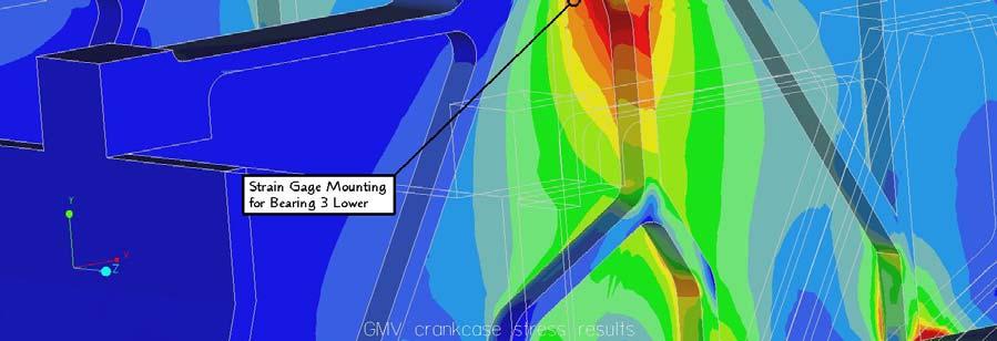
33 Figure 26 GMV-4 stress analysis results for crankshaft bearing #3 (upper web portion) with approximate strain gage location indicated Figure 27 GMV-4 stress analysis results for crankshaft bearing #3 (lower web portion) with approximate strain gage location indicated 32
34 Clark TLA-6 Frame Stress Analysis Dynamic Model Analysis A dynamic analysis of a modeled Clark TLA-6 engine with three compressors was performed so that the extent of the increase in main bearing forces due to increased load (via torque) could be better understood. Two modeling scenarios were run and compared to each other, one with the pressure trace at nominal conditions and the second with the pressure trace at an uprated condition. This modeling was performed using MSC Working Model 2D version 5.0 software and the Ricardo Wave Model. The Wave Model software provided a pressure trace based upon the engine s parameters and operating conditions. The pressure trace data maintained the location of the peak pressure at 18 ATDC. The pressure trace data was determined at a standard boost pressure of 20 psi and at an increased (uprated) boost pressure of 24 psi, a 20% increase vii. The Working Model software then was provided power piston force data, calculated from the pressure trace data; the input force profiles can be seen in Figure 28 and Figure 30. The Working Model software was also provided the compressor piston force data, which was calculated from industry data for inlet and suction gas pressures and assumed pressure transition profiles. The compressor input force data can be seen in Figure 29 and Figure 31 viii. The Working Model simulation takes into account the weights of the components that move and rotate, but all of the geometries are simplified. The pin/bearing diameters of the connecting rods and crank pins were entered and coefficients of friction were also added. The values of the coefficients of friction for the wrist pin and crank journal bearings were set to The value of the coefficient of friction for the piston rings on the cylinder wall was set to For full hydrodynamic bearings, at the given engine speed, the coefficient of friction probably could have been set to as high as 0.10 vi. The TLA model also included the piston ring frictional effects by approximating this with a slot friction element. The Working Model TLA-6 simulation setup can be seen in Figure 32 and Figure 33. The results from this modeling indicate that, as expected, the forces would increase with an increase in load, which would result from higher peak cylinder pressures. 33
35 Figure 28 TLA-6 Power piston input forces (nominal) for Working Model simulation Figure 29 TLA-6 Compressor piston input forces (nominal) for Working Model simulation 34
36 Figure 30 TLA-6 Power piston input forces (uprated) for Working Model simulation Figure 31 TLA-6 Compressor piston input forces (uprated) for Working Model simulation 35
37 Figure 32 Working Model TLA-6 power piston simulation setup with results Figure 33 Working Model TLA-6 power piston and compressor simulation setup with results 36
38 Finite Element Stress Analysis A solid model of the entire Clark TLA-6 engine, with three compressors, was created using Pro Engineer Wildfire 3-D solid modeling CAE software (see Figure 34). The crankcase that was created from engineering drawings was too complicated for Pro Mechanica to create a successful mesh, so a simplified model was created (see Figure 35 and Figure 36). A significant amount of effort went into the simplified model such that it was not so oversimplified that potentially critical stresses would be neglected during the stress analysis. This was achieved by modifying some of the complex internal features, specifically related to the crankcase web strengtheners or ribs. The overall thickness of the crankcase webs was modified such that the total volume of material was essentially the same without the ribs as compared to the original volume of the webs with the ribs. It is recognized that these simplifications could be critical and the crankcase model may need to be refined to replace some detail, however, depending upon the results, this may not be necessary. The crankcase material properties that were entered into the software were based upon gray cast iron. Pro Mechanica treats the solid model as if it were made from an ideal, isotropic material. Table 6 lists the forces applied to each of the power pistons, for the nominal condition, at a moment when a piston of interest (e.g. cylinder #1) is at peak pressure (peak force). Figure 37 illustrates the resulting nominal condition dynamic forces on the crankshaft journal bearings, where the results are in terms of the forces in the x and y directions. This result includes the effects of the compressor forces. Figure 38 illustrates the resulting dynamic forces on the crankshaft journal bearings, but without the effects of the compressors. Table 7 summarizes the results from the dynamic analysis for the nominal condition. These forces listed in Table 7 are the forces that will be used to create the load-set for the crankcase stress FEA. The orientation of the +x and +y directions correlates to the model setup in Working Model. These directions are then correlated to the +x and +y directions in Pro Engineer and the signs are modified accordingly, if necessary. 37


39 Figure 34 TLA-6 with compressors modeled in Pro Engineer - Wildfire Figure 35 TLA-6 Crankcase modeling comparison 38

40 Figure 36 Mesh of the simplified TLA-6 crankcase Cylinder Forces (lb) - Nominal Run # 1 # 2 # 3 # 4 # 5 # 6 Notes 1 152,440 4,712 3,752 25,308 5,829 30,506 Cylinder P.P. 2 4, ,440 25,308 3,752 30,506 5,829 Cylinder P.P. 3 5,829 30, ,440 4,712 3,752 25,308 Cylinder P.P. 4 30,506 5,829 4, ,440 25,308 3,752 Cylinder P.P. 5 3,752 25,308 5,829 30, ,440 4,712 Cylinder P.P. 6 25,308 3,752 30,506 5,829 4, ,440 Cylinder P.P. Table 6 Force data at individual cylinder peak force locations for the nominal TLA-6 39
41 Figure 37 Simulation results of nominal TLA (with compressor) crankshaft bearing forces Figure 38 Simulation results of nominal TLA crankshaft bearing forces 40
42 Crankcase Bearing Saddle Forces (lb) - Nominal Cylinder 1 w/ Comp. Cylinder 2 Cylinder 3 w/ Comp. Run x-dir y-dir x-dir y-dir x-dir y-dir Notes 1-2,000-75,500 11,700-69, ,200-89,410 Cylinder P.P. 2-33,600-93,820-13,800-82,350 74,600 30,900 Cylinder P.P. 3 33,580-34,530-34,185-27,960-2,000-75,500 Cylinder P.P. 4-40,600-27,120 33,140-31,470-33,600-93,820 Cylinder P.P ,200-89,410 19,250 25,280 33,580-34,530 Cylinder P.P. 6 74,600 30,900-23,700-59,100-40,600-27,120 Cylinder P.P. Crankcase Bearing Saddle Forces (lb) - Nominal Cylinder 4 Cylinder 5 w/ Comp. Cylinder 6 Notes Run x-dir y-dir x-dir y-dir x-dir y-dir 1 19,250 25,280 33,580-34,530-34,185-27,960 Cylinder P.P. 2-23,700-59,100-40,600-27,120 33,140-31,470 Cylinder P.P. 3 11,700-69, ,200-89,410 19,250 25,280 Cylinder P.P. 4-13,800-82,350 74,600 30,900-23,700-59,100 Cylinder P.P. 5-34,185-27,960-2,000-75,500 11,700-69,180 Cylinder P.P. 6 33,140-31,470-33,600-93,820-13,800-82,350 Cylinder P.P. Table 7 Working Model dynamic force results for the nominal TLA-6 with compressors Table 8 lists the forces applied to each of the power pistons, for the uprated condition, at a moment when a piston of interest (e.g. cylinder #1) is at peak pressure (peak force). Figure 39 illustrates the resulting uprated dynamic forces on the crankshaft journal bearings, where these results are also in terms of the forces in the x and y directions. This result includes the effects due to the uprated compressor forces. Figure 40 illustrates the resulting uprated dynamic forces but without the effects due to the compressor forces. Table 9 summarizes the results from the dynamic analysis for the uprated condition. These forces listed in Table 9 are the forces that will be used as the loads for the uprated crankcase stress FEA. Cylinder Forces (lb) - Uprated Run # 1 # 2 # 3 # 4 # 5 # 6 Notes 1 165,786 4,444 4,201 21,645 4,826 32,980 Cylinder P.P. 2 4, ,786 21,645 4,201 32,980 4,826 Cylinder P.P. 3 4,826 32, ,786 4,444 4,201 21,645 Cylinder P.P. 4 32,980 4,826 4, ,786 21,645 4,201 Cylinder P.P. 5 4,201 21,645 4,826 32, ,786 4,444 Cylinder P.P. 6 21,645 4,201 32,980 4,826 4, ,786 Cylinder P.P. Table 8 Force Data at individual cylinder peak force locations for the uprated TLA-6 41
43 Figure 39 Simulation results of uprated TLA (with compressor) crankshaft bearing forces Figure 40 Simulation results of uprated TLA crankshaft bearing forces 42
44 Crankcase Bearing Saddle Forces (lb) - Uprated Cylinder 1 w/ Comp. Cylinder 2 Cylinder 3 w/ Comp. Run x-dir y-dir x-dir y-dir x-dir y-dir Notes 1 2,800-90,000 11,480-69, ,500-92,190 Cylinder P.P. 2-39,900-96,300-15,600-96,380 79,000 34,000 Cylinder P.P. 3 27,300-35,180-34,900-29,460 2,800-90,000 Cylinder P.P. 4-35,550-27,930 32,860-30,590-39,900-96,300 Cylinder P.P ,500-92,190 18,650 27,680 27,300-35,180 Cylinder P.P. 6 79,000 34,000-23,920-59,540-35,550-27,930 Cylinder P.P. Crankcase Bearing Saddle Forces (lb) - Uprated Cylinder 4 Cylinder 5 w/ Comp. Cylinder 6 Notes Run x-dir y-dir x-dir y-dir x-dir y-dir 1 18,650 27,680 27,300-35,180-34,900-29,460 Cylinder P.P. 2-23,920-59,540-35,550-27,930 32,860-30,590 Cylinder P.P. 3 11,480-69, ,500-92,190 18,650 27,680 Cylinder P.P. 4-15,600-96,380 79,000 34,000-23,920-59,540 Cylinder P.P. 5-34,900-29,460 2,800-90,000 11,480-69,050 Cylinder P.P. 6 32,860-30,590-39,900-96,300-15,600-96,380 Cylinder P.P. Table 9 Working Model dynamic force results for the uprated TLA-6 with compressors As stated previously, the results listed in Table 7 and Table 9 will be used as the crankcase load-sets for the stress analysis. For each power cylinder and compressor, there are two bearing saddles in the crankcase where the load is applied. Since the sections of the crankshaft corresponding to cylinders 2, 4, and 6 only have a power piston, the loads applied to the corresponding bearing saddles have been determined from the results illustrated in Figure 38 and Figure 40, which were listed in Table 7 and Table 9, for the nominal and uprated condition, respectively. Similarly, the sections of the crankshaft corresponding to cylinders 1, 3, and 5 have the power piston and the compressor loading considerations. The loads applied to the corresponding bearing saddles for these cylinders have been determined from the results illustrated in Figure 37 and Figure 39, which were also listed in Table 7 and Table 9. Figure 41 indicates the locations of each of the crankshaft bearings and their location within the crankcase with respect to the power and compressor cylinders. Again, there are two loading conditions, nominal and uprated. One of the limitations to this method of determining the dynamic loading is that the Working Model software is limited to two-dimensional analysis as opposed to a three-dimensional analysis. Because of this limitation, the dynamic effects due to potential influences of neighboring cylinders and the flywheel have been ignored for this analysis. An example illustrating the crankcase loading can be seen in Figure 42. The loads applied to the crankcase can now be seen as the application of loads from a simply supported section of the crankshaft. It was recognized that from cylinder to cylinder there could be potential dynamic loading effects that were ignored with this 43

45 method, especially if crankshaft deflections due to vibrations were to become significant. It should be noted that, although the engine is constrained based upon near-real world engine support schemes, the software treats this as an idealized case and does not account for the degradation of grout pads and other anchoring systems. Other preliminary loads were added to the crankcase model as well, such as the weight of the upper block and the many upper block-anchoring studs that are pre-stressed. Figure 41 TLA-6 Journal bearing locations to cylinder locations 44

46 Figure 42 Application of loads to crankcase journal bearings Finite Element Stress Analysis Results The results from the stress analysis indicated the stresses did increase in some of the cases analyzed. Table 10 summarizes the results from all twelve cases that were examined. The values of stress indicated are the von Mises stress and the maximum principal stress for the standard condition and uprated condition analyses. The results have considerable variability from one cylinder at peak pressure to another. The maximum stress was a principal stress of -28,543 psi, when cylinder 2 was at peak pressure. The negative sign indicates a direction relative to the world coordinate system within Pro Engineer. Table 11 summarizes the percent difference between the results from the standard condition and the uprated condition. It is interesting to note that due to the dynamic loading condition for cylinders 3 and 4 the overall crankcase stresses actually decreased slightly. The differences between the von Mises stress and the maximum principal stress were negligible for all cases except for cylinder 4 where there was just over a 4% difference between the two types of stresses. The largest difference in stress was associated with cylinders 1 and 2 at almost 14% and just over 11%, respectively. These results can also be seen visually with the fringe plot of the crankcase stresses (see Figure 43 and Figure 44). These two figures were used to illustrate the stress distribution within the crankcase since they illustrated the highest stresses (location and magnitudes) for all cases analyzed. Although these two figures represent stress 45
47 results found in the tables for the case when cylinder 2 was at peak pressure, it becomes readily apparent that the increase in the stress distribution is actually quite limited. Since the standard condition stresses ranged from around 6 ksi to almost 26 ksi for the analyzed cases and these engines have been generally operated at the standard condition for decades, it is most probable that any fatigue effects at this stress level are negligible. This is supported by examining most fatigue data for metals where the infinite life point is assumed to be around 10 8 to 10 9 cycles, as can be seen in Figure 45. An engine operating at 300 rpm will exceed the infinite life point if it is run for only 7 continuous months. The uprated condition that was analyzed indicated a stress range of around 6 ksi to almost 29 ksi. According to the ASM (American Society for Metals) Metals Handbook, gray cast iron has a tensile strength range of 20 ksi to 60 ksi and a compressive strength range of 83 ksi to 188 ksi ix. After discussions with an industry expert x, the mechanical properties of class 30 gray cast iron was used since it is considered to be the most common material for the older generation crankcases. Class 30 gray cast iron also provides a damping effect, which is beneficial for engine applications. Class 30 gray cast iron has an ultimate tensile strength of 31 ksi and an ultimate compressive strength of 109 ksi. For this current modeling, the highest stresses were in compression. Figure 46 illustrates a modified-mohr failure theory diagram. This diagram can be used for graphically determining an approximate safety factor. For the given ultimate compressive strength of cast iron and the maximum stress for the uprated condition, the safety factor is still (best case) around 3.8 (4.3 for the nominal condition). If endurance limit reduction factors are considered, then the safety factor would be reduced, but the safety factor should still remain greater than 2. Another approach that could be pursued would be to strengthen structural components where high localized stresses occur. Stress (psi) Cylinder P.P Cylinder P.P Cylinder P.P Std. Uprated Std. Uprated Std. Uprated von Mises 16,108 18,322 20,155 22,420 9,718 9,687 Max. Principal -20,055-22,827-25,645-28,543-10,907-10,863 Cylinder P.P. Cylinder P.P. Cylinder P.P. Std. Uprated Std. Uprated Std. Uprated von Mises 6,143 6,358 15,457 16,321 9,765 10,737 Max. Principal -7,546-7,501-20,034-21,161-12,781-14,037 Table 10 FEA Results for a TLA crankcase 46
48 Percent Increase/Decrease of Stresses Cyl. 1 Cyl. 2 Cyl. 3 Cyl. 4 Cyl. 5 Cyl. 6 von Mises 13.7% 11.2% -0.3% 3.5% 5.6% 10.0% Max. Principal 13.8% 11.3% -0.4% -0.6% 5.6% 9.8% Table 11 Percent difference between results from the FEA analyses Figure 43 FEA results for bearings 2/3 with cylinder 2 at peak pressure and standard conditions 47


49 Figure 44 FEA Results for bearings 2/3 with cylinder 2 at peak pressure and uprated conditions Figure 45 Reversed bending fatigue life of gray cast iron ix 48
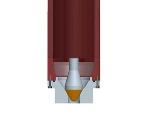
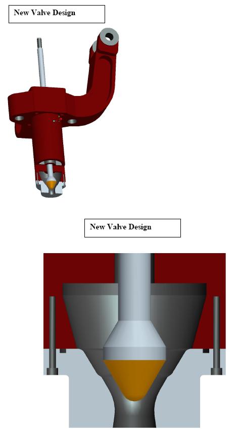
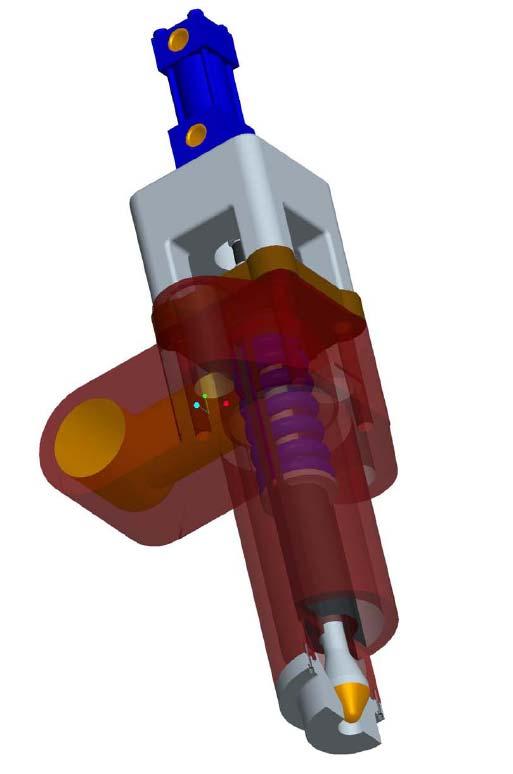
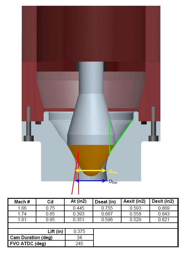
50 Figure 46 Goodman diagram for indicating safe and unsafe fatigue zones ix 2.3 Hydraulically Actuated Mechanical Fuel Injection System A hydraulically actuated, inwardly opening, mechanical fuel injection valve system was designed for a Clark TLA engine. This design however has potential to be applied to many different engine models. High pressure fuel injection (HPFI) is a technology that is proven to improve efficiency and decrease emissions by enhancing the mixing of fuel and air. HPFI systems currently employed in the field are poppet valves, and contain significant fluid losses due to the flow path created. These systems typically required 500 psi fuel pressure to achieve adequate fuel and air mixing. This new design allows for the introduction of natural gas with jet energy equivalent to commercially available HPFI systems, but with a 80% fuel pressure reduction. The required fuel pressure for the new design is 100 psi. By creating a fuel injection event with equivalent jet energy, the benefits of enhanced mixing are achieved, promoting the extension of the lean limit and associated emissions reductions. The hydraulically actuated mechanical fuel injection valve body is the OEM fuel injection valve body, with minor modifications. These modifications consist primarily of relatively simple machining operations, most significant of which is the modification of the lower portion of the body to allow for the mounting of a fuel convergent-divergent nozzle body. This nozzle body allows for a much more efficient fuel flow path and provides the seating area for the new fuel valve, which acts more like the typical fuel injection needle (inwardly opening). Images of the original valve design vs. the new valve design can be seen in Figure 47 and Figure 48. Note that the inwardly opening design eliminates regions that can trap fuel, which are present in other convergingdiverging nozzles designed to interface with the standard poppet valves. 49


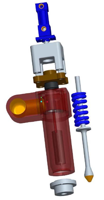
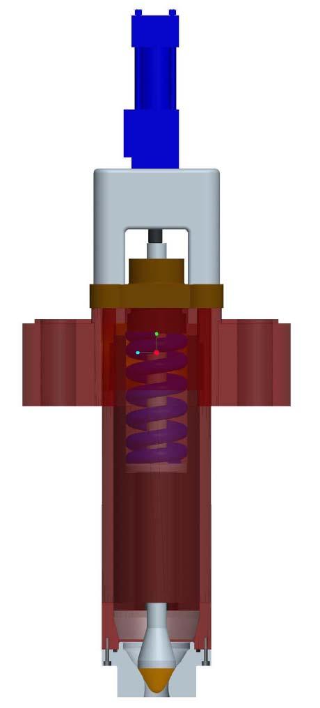
51 Figure 47 Cross-section view of typical TLA fuel injection valve Figure 48 Cross-section view of new fuel injection valve Fuel injection on a typical TLA is initiated by a fuel cam and rocker arm assembly. Fuel injection with the new hydraulic-mechanical system is initiated by a fuel cam translating a hydraulic cylinder rod, hydraulically coupled to another hydraulic cylinder which opens the fuel valve. Figure 49 and Figure 50 illustrate the concept of the new design. The new system utilizes the engine oil as the hydraulic fluid such that no new fluid needs to be introduced. A pressure relief valve was designed into the new system to allow for removal of air that may be entrained or trapped within the oil. This also facilitates oil circulation for cooling. With each stroke of the fuel injector, a portion of the cam lift profile will over-stroke the hydraulic cylinder attached to the fuel injector. This will cause the pressure relief valve to open, allowing hot oil to pass into the primary engine oil flow to be cooled through the engine oil heat exchanger. New oil is introduced into the fuel injector hydraulic circuit from an engine oil reservoir during non-actuating periods. A circuit schematic of this concept can be seen in Figure 51. This new design was developed at the CSU EECL in collaboration with Dresser-Rand. Dresser-Rand has expressed interest in developing this technology as a commercially available fuel injection system. An engineering drawing package for this system is provided in Appendix B. 50


52 Figure 49 Hydraulically actuated mechanical fuel injection valve assembly Figure 50 Hydraulically actuated mechanical fuel injection valve system 51
53 Figure 51 Hydraulic schematic for new fuel valve design 2.4 Uprate Systems Test Plan The uprate systems test plan has been created and submitted to DOE. This document provides a path for a logical testing procedure. The testing procedures are developed to quantify the engine performance parameters with respect to emissions and power output. 52
54 3.0 Conclusions From the investigations for this project, several key conclusions have been determined. The CFD analysis has indicated significant benefits from high-pressure fuel injection (HPFI). The fuel mixing with the standard mechanical gas admission valve (MGAV) of low-pressure fuel indicates that the fuel gas has a propensity to attach to the surface of the head producing a curtain effect. This does not promote rapid and homogeneous mixing with the air in the combustion chamber. Conversely, the HPFI method injects a highenergy flow of fuel into the combustion chamber and the mixing is significantly improved. Comparing the MGAV results to the HPFI results, there is a high level of mixedness by 60 BTDC with the HPFI system as compared to the MGAV system, which never really achieves the same level of mixing. Additionally, the investigation also provided evidence that modifying the piston crown with a sombrero style surface does not improve mixing compared to the standard TLA combustion chamber piston surface (with HPFI). A modal analysis of three engine crankshafts was performed using FEA. All three crankshafts had a similar range of results. For a TLA-6 crankshaft the first harmonic was found to be at 59 Hz. An HBA-6 crankshaft was analyzed and its first harmonic was found to be 54 Hz. The third crankshaft analyzed was for a GMV-10 and its first harmonic was found to be at 56 Hz. All of these modal analyses utilized the lumped mass assumption, to account for all of the attached slider crank components, and flywheels were also included. The results from all three analyses were slightly higher than expected, but this method was evaluated for its potential use as a method to give an estimate for a crankshafts natural frequency. Crankshafts are desired to be operated at speeds far away from the natural frequency and the results from these analyses support this goal. The TLA-6, HBA-6, and GMV-10 crankshaft natural frequency speeds were 3,540 rpm, 3,240 rpm, and 3,360 rpm, respectively. Given consideration of their typical operating speed, none of these crankshafts are near a critical order speed when operated at 300 rpm. FEA results for the TLA crankcase indicate that the strength will be adequate to support the additional stresses due to uprating the engine. The analysis results predict a new maximum stress of less than 23ksi, in compression, which will still provide for a large safety factor of nearly 5. These predicted new stresses are also still within acceptable limits with respect to the fatigue life of gray cast iron. The modeling process developed could be valuable in the investigation of other candidate engines for uprating. 53
55 A new hydraulically actuated, inwardly opening, mechanical fuel injection system was designed in cooperation with Dresser-Rand. This new valve design takes advantage of an improved fuel flow path which reduces fluid losses. By reducing fluid losses the natural gas need only be compressed to approximately 100 psi instead of approximately 500 psi necessary for current HPFI systems. This proposed system provides essentially the same high-energy flow as current 500 psi HPFI systems but with an 80% reduction of required natural gas fuel pressure. 54
56 4.0 Summary 4.1 Summary of Accomplishments During this period of research, the following key accomplishments were achieved: CFD analysis has shown HPFI significantly improves in-cylinder gas mixing Improved in-cylinder gas mixing extends the lean limit of operation, reducing maximum in-cylinder temperatures and hence assists in lowering NO x generation during combustion Modal analysis of three crankshafts completed Results for TLA, HBA, and GMV crankshafts indicate sufficient separation between typical operation speed of 300 rpm and a 10 th order critical speed range of 320 rpm to 354 rpm FEA stress analysis has indicated that an uprated TLA will have a maximum increase in frame stress of approximately 14% for a 20% increase in torque FEA stress analysis has also indicated that an uprated TLA will have a maximum stress, in compression, of approximately 23ksi, which maintains a safety factor of almost 5 FEA stress modeling could be a very effective prediction tool for evaluating potential structural issues for uprate other candidate engines 55
57 REFERENCES i ii iii iv v vi vii viii ix x Norton, R., Machine Design: An Integrated Approach 2 nd edition (Upper Saddle River, NJ: Prentice-Hall, 2000), Heath, A., McNamara, P., Crankshaft Stress Analysis Combination of Finite Element and Classical Analysis Techniques, Journal of Engineering for Gas Turbines and Power (1990): Priebsch, H., Affenszeller, J., Gran, S., Prediction Technique for Stress and Vibration of Nonlinear Supported, Rotating Crankshafts, Journal of Engineering for Gas Turbines and Power (1993): Bargis, E., Vullo, V., Garro, A., Crankshaft Design and Evaluation Part 2 A Modern Design Method: Modal Analysis, Reliability, Stress Analysis and Failure Prevention Methods in Mechanical Design Conference (San Francisco, Ca: American Society of Mechanical Engineers, 1980), Dennis W. Schmitt, Frame Stress and Crankshaft Modal Analysis on Large Bore Natural Gas Engines, Masters Thesis, Colorado State University, Fall Beardmore, Roy. Coefficients of Friction. Friction Factors < (Feb. 2005). Schmitt, D., Olsen, D., Willson, B., Development and Deployment for Pipeline Compressor Engines, Final Report, GRI Contract #GRI-04/0065, Jeff Clegg, El Paso Corporation at the Colorado Interstate Gas Company-Rawlins, Wyoming Compressor Station. <Jeffrey.Clegg@ElPaso.com> Compressor Information. July 9, Research Communication. Metals Handbook 10 th edition (Materials Park, OH: ASM International, 1990), Terry Smith, Gas Industry Consultant, personal communications, February

58 Appendix A OEM Communications 1
59 2
60 3
61 4

62 5

63 6
64 7
65 8
66 9
67 10
68 11
69 12
70 13
71 14
72 15
73 16
74 17
75 18
76 19

77 Appendix B Hydraulically Actuated Mechanical Fuel Injection Valve 20
78 21
79 22
80 23
81 24
82 25
83 26
84 27
85 28
86 29
87 30
88 31
89 32
90 33
91 34
92 35
93 36
94 37
95 38
96 39
97 40
98 41
99 42
100 43
101 44
102 45
103 46
Hybrid Electric Vehicle End-of-Life Testing On Honda Insights, Honda Gen I Civics and Toyota Gen I Priuses
 INL/EXT-06-01262 U.S. Department of Energy FreedomCAR & Vehicle Technologies Program Hybrid Electric Vehicle End-of-Life Testing On Honda Insights, Honda Gen I Civics and Toyota Gen I Priuses TECHNICAL
Load Analysis and Multi Body Dynamics Analysis of Connecting Rod in Single Cylinder 4 Stroke Engine
 IJSRD - International Journal for Scientific Research & Development Vol. 3, Issue 08, 2015 ISSN (online): 2321-0613 Load Analysis and Multi Body Dynamics Analysis of Connecting Rod in Single Cylinder 4
Influence of Cylinder Bore Volume on Pressure Pulsations in a Hermetic Reciprocating Compressor
 Purdue University Purdue e-pubs International Compressor Engineering Conference School of Mechanical Engineering 2014 Influence of Cylinder Bore Volume on Pressure Pulsations in a Hermetic Reciprocating
6340(Print), ISSN (Online) Volume 3, Issue 3, Sep- Dec (2012) IAEME AND TECHNOLOGY (IJMET)
, ISSN (Online) Volume 3, Issue 3, Sep- Dec (2012) IAEME AND TECHNOLOGY (IJMET)") INTERNATIONAL International Journal of Mechanical JOURNAL Engineering OF MECHANICAL and Technology (IJMET), ENGINEERING ISSN 0976 AND TECHNOLOGY (IJMET) ISSN 0976 6340 (Print) ISSN 0976 6359 (Online) Volume
INTERNATIONAL International Journal of Mechanical JOURNAL Engineering OF MECHANICAL and Technology (IJMET), ENGINEERING ISSN 0976 AND TECHNOLOGY (IJMET) ISSN 0976 6340 (Print) ISSN 0976 6359 (Online) Volume
MASTER \ C. Idaho National Engineering Laboratory. INEL 96J014t we.l~%/0o/60 PREPRINT. MOTOR-OPERATOR GEARBOX EFFICIENCY 5 i u.
 INEL 96J014t we.l~%/0o/60 PREPRINT \ C Idaho National Engineering Laboratory MOTOR-OPERATOR GEARBOX EFFICIENCY 5 i u.^ 1 Q Kevin G. DeWall, John C. Watkins, Donovan Bramwell The Fourth NRC/ASME Symposium
Reduction of Self Induced Vibration in Rotary Stirling Cycle Coolers
 Reduction of Self Induced Vibration in Rotary Stirling Cycle Coolers U. Bin-Nun FLIR Systems Inc. Boston, MA 01862 ABSTRACT Cryocooler self induced vibration is a major consideration in the design of IR
MODELING SUSPENSION DAMPER MODULES USING LS-DYNA
 MODELING SUSPENSION DAMPER MODULES USING LS-DYNA Jason J. Tao Delphi Automotive Systems Energy & Chassis Systems Division 435 Cincinnati Street Dayton, OH 4548 Telephone: (937) 455-6298 E-mail: Jason.J.Tao@Delphiauto.com
COMPUTATIONAL FLOW MODEL OF WESTFALL'S 2900 MIXER TO BE USED BY CNRL FOR BITUMEN VISCOSITY CONTROL Report R0. By Kimbal A.
 COMPUTATIONAL FLOW MODEL OF WESTFALL'S 2900 MIXER TO BE USED BY CNRL FOR BITUMEN VISCOSITY CONTROL Report 412509-1R0 By Kimbal A. Hall, PE Submitted to: WESTFALL MANUFACTURING COMPANY May 2012 ALDEN RESEARCH
Stress Analysis of Engine Camshaft and Choosing Best Manufacturing Material
 Stress Analysis of Engine Camshaft and Choosing Best Manufacturing Material Samta Jain, Mr. Vikas Bansal Rajasthan Technical University, Kota (Rajasathan), India Abstract This paper presents the modeling
ENERGY ANALYSIS OF A POWERTRAIN AND CHASSIS INTEGRATED SIMULATION ON A MILITARY DUTY CYCLE
 U.S. ARMY TANK AUTOMOTIVE RESEARCH, DEVELOPMENT AND ENGINEERING CENTER ENERGY ANALYSIS OF A POWERTRAIN AND CHASSIS INTEGRATED SIMULATION ON A MILITARY DUTY CYCLE GT Suite User s Conference: 9 November
BLAST CAPACITY ASSESSMENT AND TESTING A-60 OFFSHORE FIRE DOOR
 BLAST CAPACITY ASSESSMENT AND TESTING Final Report December 11, 2008 A-60 OFFSHORE FIRE DOOR Prepared for: JRJ Alum Fab, Inc. Prepared by: Travis J. Holland Michael J. Lowak John R. Montoya BakerRisk Project
Variable Intake Manifold Development trend and technology
 Variable Intake Manifold Development trend and technology Author Taehwan Kim Managed Programs LLC (tkim@managed-programs.com) Abstract The automotive air intake manifold has been playing a critical role
FEA of the Forged Steel Crankshaft by Hypermesh
 Global Journal of Researches in Engineering Mechanical and Mechanics Engineering Volume 13 Issue 4 Version 1.0 Year 2013 Type: Double Blind Peer Reviewed International Research Journal Publisher: Global
Probabilistic Analysis for Resolving Fatigue Failures of the Connecting Rod Oil Hole
 Probabilistic Analysis for Resolving Fatigue Failures of the Connecting Rod Oil Hole Jianxiong Chen Sr. Engineering Specialist Applied Mechanics Dept., Copeland Corporation, Sidney, Ohio, USA Donald Draper
Determination of Spring Modulus for Several Types of Elastomeric Materials (O-rings) and Establishment of an Open Database For Seals*
 and Establishment of an Open Database For Seals*") Determination of Spring Modulus for Several Types of Elastomeric Materials (O-rings) and Establishment of an Open Database For Seals* W. M. McMurtry and G. F. Hohnstreiter Sandia National Laboratories,
Determination of Spring Modulus for Several Types of Elastomeric Materials (O-rings) and Establishment of an Open Database For Seals* W. M. McMurtry and G. F. Hohnstreiter Sandia National Laboratories,
Static Analysis of Crankcase and Crankshaft of Single Cylinder Four Stroke Diesel Engine
 Static Analysis of Crankcase and Crankshaft of Single Cylinder Four Stroke Diesel Engine Kakade Pratik 1 Post Graduate Student kakadepratik@gmail.com Pasarkar M. D. 2 Assistant Professor mdpasarkar@gmail.com
Foundations of Thermodynamics and Chemistry. 1 Introduction Preface Model-Building Simulation... 5 References...
 Contents Part I Foundations of Thermodynamics and Chemistry 1 Introduction... 3 1.1 Preface.... 3 1.2 Model-Building... 3 1.3 Simulation... 5 References..... 8 2 Reciprocating Engines... 9 2.1 Energy Conversion...
Comparing FEM Transfer Matrix Simulated Compressor Plenum Pressure Pulsations to Measured Pressure Pulsations and to CFD Results
 Purdue University Purdue e-pubs International Compressor Engineering Conference School of Mechanical Engineering 2012 Comparing FEM Transfer Matrix Simulated Compressor Plenum Pressure Pulsations to Measured
Heat treatment Elimination in Forged steel Crankshaft of Two-stage. compressor.
 Research Journal of Engineering Sciences ISSN 2278 9472 Heat treatment Elimination in Forged steel Crankshaft of Two-stage Compressor Abstract Lakshmanan N. 1, Ramachandran G.M. 1 and Saravanan K. 2 1
Finite Element Analysis of Clutch Piston Seal
 Finite Element Analysis of Clutch Piston Seal T. OYA * F. KASAHARA * *Research & Development Center Tribology Research Department Three-dimensional finite element analysis was used to simulate deformation
Engine Cycles. T Alrayyes
 Engine Cycles T Alrayyes Introduction The cycle experienced in the cylinder of an internal combustion engine is very complex. The cycle in SI and diesel engine were discussed in detail in the previous
A Study of EGR Stratification in an Engine Cylinder
 A Study of EGR Stratification in an Engine Cylinder Bassem Ramadan Kettering University ABSTRACT One strategy to decrease the amount of oxides of nitrogen formed and emitted from certain combustion devices,
THE IMPACT OF BIODIESEL FUEL BLENDS ON AFTERTREATMENT DEVICE PERFORMANCE IN LIGHT-DUTY VEHICLES
 THE IMPACT OF BIODIESEL FUEL BLENDS ON AFTERTREATMENT DEVICE PERFORMANCE IN LIGHT-DUTY VEHICLES Matthew Thornton NREL, Marek Tatur and Dean Tomazic FEV Engine Technology Inc. National Biodiesel Conference
Glendale Water & Power Smart Grid Project
 Glendale Water & Power Smart Grid Project Key Dates in Project History Key Dates Project History On July 10, 2007, City Council directed GWP to develop a long term plan for smart meters On October 23,
Crankcase scavenging.
 Software for engine simulation and optimization www.diesel-rk.bmstu.ru The full cycle thermodynamic engine simulation software DIESEL-RK is designed for simulating and optimizing working processes of two-
INTERNATIONAL JOURNAL OF DESIGN AND MANUFACTURING TECHNOLOGY (IJDMT) CONSTANT SPEED ENGINE CONROD SOFT VALIDATION & OPTIMIZATION
 CONSTANT SPEED ENGINE CONROD SOFT VALIDATION & OPTIMIZATION") INTERNATIONAL JOURNAL OF DESIGN AND MANUFACTURING TECHNOLOGY (IJDMT) International Journal of Design and Manufacturing Technology (IJDMT), ISSN 0976 6995(Print), ISSN 0976 6995 (Print) ISSN 0976 7002 (Online)
INTERNATIONAL JOURNAL OF DESIGN AND MANUFACTURING TECHNOLOGY (IJDMT) International Journal of Design and Manufacturing Technology (IJDMT), ISSN 0976 6995(Print), ISSN 0976 6995 (Print) ISSN 0976 7002 (Online)
Transient Thermal Analysis of Screw Compressors, Part III: Transient Thermal Analysis of a Screw Compressor to Determine Rotor-to-Rotor Clearances
 Purdue University Purdue e-pubs International Compressor Engineering Conference School of Mechanical Engineering 26 Transient Thermal Analysis of Screw Compressors, Part III: Transient Thermal Analysis
Components of Hydronic Systems
 Valve and Actuator Manual 977 Hydronic System Basics Section Engineering Bulletin H111 Issue Date 0789 Components of Hydronic Systems The performance of a hydronic system depends upon many factors. Because
4lliedSig nal. Development of a Digital Control Unit to Displace Diesel Fuel With Natural Gas. Federal Manufacturing & Tech nolog ies. A. D.
 Development of a Digital Control Unit to Displace Diesel Fuel With Natural Gas Federal Manufacturing & Tech nolog ies A. D. Talbott KCP-613-5913 I Published March 1997 Final ReporVProject Accomplishments
Chapter 4. Vehicle Testing
 Chapter 4 Vehicle Testing The purpose of this chapter is to describe the field testing of the controllable dampers on a Volvo VN heavy truck. The first part of this chapter describes the test vehicle used
MULTI-BODY DYNAMIC ANALYSIS OF AN IC ENGINE PISTON FOR SHAPE OPTIMIZATION
 Int. J. Mech. Eng. & Rob. Res. 2014 Shivayogi S Hiremath and I G Bhavi, 2014 Research Paper ISSN 2278 0149 www.ijmerr.com Vol. 3, No. 4, October 2014 2014 IJMERR. All Rights Reserved MULTI-BODY DYNAMIC
Steel Intensive Engine Executive Summary
 a business unit of AISI www.smdisteel.org Steel Intensive Engine Executive Summary 2013 Contributors MAHLE Long Products Market Development Group members: Gerdau Nucor Corporation The Timkin Company Presentation
Chapter 7: Thermal Study of Transmission Gearbox
 Chapter 7: Thermal Study of Transmission Gearbox 7.1 Introduction The main objective of this chapter is to investigate the performance of automobile transmission gearbox under the influence of load, rotational
Accelerating the Development of Expandable Liner Hanger Systems using Abaqus
 Accelerating the Development of Expandable Liner Hanger Systems using Abaqus Ganesh Nanaware, Tony Foster, Leo Gomez Baker Hughes Incorporated Abstract: Developing an expandable liner hanger system for
Numerically Analysing the Effect of EGR on Emissions of DI Diesel Engine Having Toroidal Combustion Chamber Geometry
 Numerically Analysing the Effect of EGR on Emissions of DI Diesel Engine Having Toroidal Combustion Chamber Geometry Jibin Alex 1, Biju Cherian Abraham 2 1 Student, Dept. of Mechanical Engineering, M A
MAST R OS71 NOV DOE/METC/C-96/7207. Combustion Oscillation: Chem,;a Purge Time. Contrc Showing Mechanistic.ink to Recirculation Zone
 DOE/METC/C-96/727 Combustion Oscillation: Chem,;a Purge Time Contrc Showing Mechanistic.ink to Recirculation Zone Authors: R.S. Gemmen GA, Richards M.J. Yip T.S. Norton Conference Title: Eastern States
Analytical and Experimental Evaluation of Cylinder Deactivation on a Diesel Engine. S. Pillai, J. LoRusso, M. Van Benschoten, Roush Industries
 Analytical and Experimental Evaluation of Cylinder Deactivation on a Diesel Engine S. Pillai, J. LoRusso, M. Van Benschoten, Roush Industries GT Users Conference November 9, 2015 Contents Introduction
Utilization of Associated Gas to Power Drilling Rigs A Demonstration in the Bakken
 Utilization of Associated Gas to Power Drilling Rigs A Demonstration in the Bakken Bakken Artificial Lift and Production Denver, Colorado September 24 25, 2013 Chad Wocken*, John Harju, Grant Dunham, and
A STUDY OF THE CENTRIFUGAL COMPRESSOR DISCHARGE PIPELINE CONSTRAINED OSCILLATION. KIRILL SOLODYANKIN*, JIŘÍ BĚHAL ČKD KOMPRESORY, a.s.
 A STUDY OF THE CENTRIFUGAL COMPRESSOR DISCHARGE PIPELINE CONSTRAINED OSCILLATION KIRILL SOLODYANKIN*, JIŘÍ BĚHAL ČKD KOMPRESORY, a.s. Abstract: The paper presents a solution of a pipeline constrained oscillation
Using Kinetic Energy for Plunger Lift Safety and Maintenance
 Gas Well Deliquification Workshop Sheraton Hotel, February 20 22, 2017 Using Kinetic Energy for Plunger Lift Safety and Maintenance Mark Scantlebury, President and CEO Extreme Telematics Corp. THE CHANGING
A Study of Lead-Acid Battery Efficiency Near Top-of-Charge and the Impact on PV System Design
 A Study of Lead-Acid Battery Efficiency Near Top-of-Charge and the Impact on PV System Design John W. Stevens and Garth P. Corey Sandia National Laboratories, Photovoltaic System Applications Department
2010 Gas Turbine Industrial Fellowship Report
 2010 Gas Turbine Industrial Fellowship Report Thermo-acoustic Network Software Validation Solar Turbines Incorporated South Carolina Institute for Energy Studies Clemson University Prepared By: John Pagliaro
Design and Stress Analysis of Crankshaft for Single Cylinder 4-Stroke Diesel Engine
 Design and Stress Analysis of Crankshaft for Single Cylinder 4-Stroke Diesel Engine Amit Solanki #1, Jaydeepsinh Dodiya #2, # Mechanical Engg.Deptt, C.U.Shah University, Wadhwan city, Gujarat, INDIA Abstract
Harmonic Analysis of Reciprocating Compressor Crankcase Assembly
 IOSR Journal of Engineering (IOSRJEN) www.iosrjen.org ISSN (e): 2250-3021, ISSN (p): 2278-8719 PP 16-20 Harmonic Analysis of Reciprocating Compressor Crankcase Assembly A. A. Dagwar 1, U. S. Chavan 1,
REPORT ON TOYOTA/PRIUS MOTOR DESIGN AND MANUFACTURING ASSESSMENT
 ORNL/TM-2004/137 REPORT ON TOYOTA/PRIUS MOTOR DESIGN AND MANUFACTURING ASSESSMENT J. S. Hsu C. W. Ayers C. L. Coomer Oak Ridge National Laboratory This report was prepared as an account of work sponsored
SAMPLE STUDY MATERIAL
 IC Engine - ME GATE, IES, PSU 1 SAMPLE STUDY MATERIAL Mechanical Engineering ME Postal Correspondence Course Internal Combustion Engine GATE, IES & PSUs IC Engine - ME GATE, IES, PSU 2 C O N T E N T 1.
Fatigue Life Estimation of Chassis Frame FESM Bracket for Commercial Vehicle
 Fatigue Life Estimation of Chassis Frame FESM Bracket for Commercial Vehicle Shivakumar M.M 1, Nirmala L 2 ¹M-Tech Student, Dept. of Mechanical Engineering,K.S Institute of Technology, Bangalore, India
Marc ZELLAT, Driss ABOURI and Stefano DURANTI CD-adapco
 17 th International Multidimensional Engine User s Meeting at the SAE Congress 2007,April,15,2007 Detroit, MI RECENT ADVANCES IN DIESEL COMBUSTION MODELING: THE ECFM- CLEH COMBUSTION MODEL: A NEW CAPABILITY
Combustion PVM-MF. The PVM-MF model has been enhanced particularly for dualfuel
 Contents Extensive new capabilities available in STAR-CD/es-ice v4.20 Combustion Models see Marc Zellat presentation Spray Models LES New Physics Developments in v4.22 Combustion Models PVM-MF Crank-angle
Development, Implementation, and Validation of a Fuel Impingement Model for Direct Injected Fuels with High Enthalpy of Vaporization
 Development, Implementation, and Validation of a Fuel Impingement Model for Direct Injected Fuels with High Enthalpy of Vaporization (SAE Paper- 2009-01-0306) Craig D. Marriott PE, Matthew A. Wiles PE,
Abaqus Technology Brief. Prediction of B-Pillar Failure in Automobile Bodies
 Prediction of B-Pillar Failure in Automobile Bodies Abaqus Technology Brief TB-08-BPF-1 Revised: September 2008 Summary The B-pillar is an important load carrying component of any automobile body. It is
Kolbenschmidt Pierburg Group
 Kolbenschmidt Pierburg Group KS Aluminum Pistons for Truck Applications Requirements The development of on- and off-highway diesel engines for a wide spectrum of applications is affected by global emission
Model-Based Integrated High Penetration Renewables Planning and Control Analysis
 Model-Based Integrated High Penetration Renewables Planning and Control Analysis October 22, 2015 Steve Steffel, PEPCO Amrita Acharya-Menon, PEPCO Jason Bank, EDD SUNRISE Department of Energy Grant Model-Based
Variable Valve Drive From the Concept to Series Approval
 Variable Valve Drive From the Concept to Series Approval New vehicles are subject to ever more stringent limits in consumption cycles and emissions. At the same time, requirements in terms of engine performance,
Sacramento Municipal Utility District s EV Innovators Pilot
 Sacramento Municipal Utility District s EV Innovators Pilot Lupe Jimenez November 20, 2013 Powering forward. Together. Agenda SMUD Snapshot Pilot Plan v Background v At-a-Glance v Pilot Schedule Treatment
Cost Benefit Analysis of Faster Transmission System Protection Systems
 Cost Benefit Analysis of Faster Transmission System Protection Systems Presented at the 71st Annual Conference for Protective Engineers Brian Ehsani, Black & Veatch Jason Hulme, Black & Veatch Abstract
Alan R. Klembczyk, Chief Engineer Taylor Devices, Inc. North Tonawanda, NY
 SIMULATION, DEVELOPMENT, AND FIELD MEASUREMENT VALIDATION OF AN ISOLATION SYSTEM FOR A NEW ELECTRONICS CABINET IN THE SPACE SHUTTLE LAUNCH ENVIRONMENT WITHIN THE MOBILE LAUNCH PLATFORM Alan R. Klembczyk,
EFFECTS OF LOCAL AND GENERAL EXHAUST VENTILATION ON CONTROL OF CONTAMINANTS
 Ventilation 1 EFFECTS OF LOCAL AND GENERAL EXHAUST VENTILATION ON CONTROL OF CONTAMINANTS A. Kelsey, R. Batt Health and Safety Laboratory, Buxton, UK British Crown copyright (1) Abstract Many industrial
Marc ZELLAT, Driss ABOURI, Thierry CONTE and Riyad HECHAICHI CD-adapco
 16 th International Multidimensional Engine User s Meeting at the SAE Congress 2006,April,06,2006 Detroit, MI RECENT ADVANCES IN SI ENGINE MODELING: A NEW MODEL FOR SPARK AND KNOCK USING A DETAILED CHEMISTRY
STEALTH INTERNATIONAL INC. DESIGN REPORT #1001 IBC ENERGY DISSIPATING VALVE FLOW TESTING OF 12 VALVE
 STEALTH INTERNATIONAL INC. DESIGN REPORT #1001 IBC ENERGY DISSIPATING VALVE FLOW TESTING OF 12 VALVE 2 This report will discuss the results obtained from flow testing of a 12 IBC valve at Alden Research
Comparison of Velocity Vector Components in a Di Diesel Engine: Analysis through Cfd Simulation
 IOSR Journal of Mechanical and Civil Engineering (IOSR-JMCE) e-issn: 2278-1684,p-ISSN: 2320-334X PP. 55-60 www.iosrjournals.org Comparison of Velocity Vector Components in a Di Diesel Engine: Analysis
Scroll Compressor Oil Pump Analysis
 IOP Conference Series: Materials Science and Engineering PAPER OPEN ACCESS Scroll Compressor Oil Pump Analysis To cite this article: S Branch 2015 IOP Conf. Ser.: Mater. Sci. Eng. 90 012033 View the article
Alternative Fuel Price Report
 July 2016 Natural Gas Ethanol Propane Biodiesel CLEAN CITIES Alternative Fuel Price Report Welcome to the July 2016 issue! The Clean Cities Alternative Fuel Price Report is a quarterly report designed
A Cost Benefit Analysis of Faster Transmission System Protection Schemes and Ground Grid Design
 A Cost Benefit Analysis of Faster Transmission System Protection Schemes and Ground Grid Design Presented at the 2018 Transmission and Substation Design and Operation Symposium Revision presented at the
Simulating Rotary Draw Bending and Tube Hydroforming
 Abstract: Simulating Rotary Draw Bending and Tube Hydroforming Dilip K Mahanty, Narendran M. Balan Engineering Services Group, Tata Consultancy Services Tube hydroforming is currently an active area of
PIPELINE REPAIR OF CORROSION AND DENTS: A COMPARISON OF COMPOSITE REPAIRS AND STEEL SLEEVES
 Proceedings of the 2014 10th International Pipeline Conference IPC2014 September 29 - October 3, 2014, Calgary, Alberta, Canada IPC2014-33410 PIPELINE REPAIR OF CORROSION AND DENTS: A COMPARISON OF COMPOSITE
Transmission Error in Screw Compressor Rotors
 Purdue University Purdue e-pubs International Compressor Engineering Conference School of Mechanical Engineering 2008 Transmission Error in Screw Compressor Rotors Jack Sauls Trane Follow this and additional
2B.3 - Free Piston Engine Hydraulic Pump
 2B.3 - Free Piston Engine Hydraulic Pump Georgia Institute of Technology Milwaukee School of Engineering North Carolina A&T State University Purdue University University of Illinois, Urbana-Champaign University
Design and Optimization of HTV Fuel Tank Assembly by Finite Element Analysis
 Design and Optimization of HTV Fuel Tank Assembly by Finite Element Analysis Ms.Baseera Banushaik PG Student, Department of Mechanical Engineering, Malla Reddy College of Engineering, Secunderabad. Ms.I.Prasanna
SpiritPFC Torque/Horsepower Comparison Dynamometer Test Date: 5/7/2006
 SpiritPFC / Comparison Dynamometer Test Date: 5/7/2006 Dynamometer Test Outline: Contained within this document you will find data collected using a Dyno Datamite engine dynamometer hardware and software
Test Rig Design for Large Supercritical CO 2 Turbine Seals
 Test Rig Design for Large Supercritical CO 2 Turbine Seals Presented by: Aaron Rimpel Southwest Research Institute San Antonio, TX The 6th International Supercritical CO 2 Power Cycles Symposium March
Simulation of Performance Parameters of Spark Ignition Engine for Various Ignition Timings
 Research Article International Journal of Current Engineering and Technology ISSN 2277-4106 2013 INPRESSCO. All Rights Reserved. Available at http://inpressco.com/category/ijcet Simulation of Performance
Thermal Stress Analysis of Diesel Engine Piston
 International Conference on Challenges and Opportunities in Mechanical Engineering, Industrial Engineering and Management Studies 576 Thermal Stress Analysis of Diesel Engine Piston B.R. Ramesh and Kishan
Comparison of Swirl, Turbulence Generating Devices in Compression ignition Engine
 Available online atwww.scholarsresearchlibrary.com Archives of Applied Science Research, 2016, 8 (7):31-40 (http://scholarsresearchlibrary.com/archive.html) ISSN 0975-508X CODEN (USA) AASRC9 Comparison
Ignition Improvements to Support High-efficiency Natural Gas Combustion
 Ignition Improvements to Support High-efficiency Natural Gas Combustion 2005 UW ERC Symposium on Low- Emissions Combustion Technologies for Internal Combustion Engines Corey Honl Sr. Development Engineer
GLOW PLUG INTEGRATED CYLINDER PRESSURE SENSOR FOR CLOSED LOOP ENGINE CONTROL
 Journal of KONES Internal Combustion Engines 2005, vol. 12, 3-4 GLOW PLUG INTEGRATED CYLINDER PRESSURE SENSOR FOR CLOSED LOOP ENGINE CONTROL Marek T. Wlodarczyk Optrand, Inc. 46155 Five Mile Rd. Plymouth,
FRONTAL OFF SET COLLISION
 FRONTAL OFF SET COLLISION MARC1 SOLUTIONS Rudy Limpert Short Paper PCB2 2014 www.pcbrakeinc.com 1 1.0. Introduction A crash-test-on- paper is an analysis using the forward method where impact conditions
TORSIONAL VIBRATION MODELLING AND ANALYSIS CONTINUED. Beta Machinery Analysis Ltd., Calgary, AB, Canada, T3C 0J7 ABSTRACT
 TORSIONAL VIBRATION MODELLING AND ANALYSIS CONTINUED Rodney R. Varty, B.Sc. Project Analyst John D. Harvey, P.Eng Training Manager Beta Machinery Analysis Ltd., Calgary, AB, Canada, T3C 0J7 ABSTRACT The
CHAPTER 6 MECHANICAL SHOCK TESTS ON DIP-PCB ASSEMBLY
 135 CHAPTER 6 MECHANICAL SHOCK TESTS ON DIP-PCB ASSEMBLY 6.1 INTRODUCTION Shock is often defined as a rapid transfer of energy to a mechanical system, which results in a significant increase in the stress,
Combustion Performance
 Analysis of Crankshaft Speed Fluctuations and Combustion Performance Ramakrishna Tatavarthi Julian Verdejo GM Powertrain November 10, 2008 Overview introduction definition of operating map speed-load d
DESIGN AND ANALYSIS OF CRANKSHAFT FOUR CYLINDER
 DESIGN AND ANALYSIS OF CRANKSHAFT FOUR CYLINDER Manoj Kumar Ojha, Subrat Kumar Baral, Sushree Sefali Mishra Assistant Professor, Department of Mechanical Engineering, Gandhi Engineering College, Bhubaneswar
Electromagnetic Fully Flexible Valve Actuator
 Electromagnetic Fully Flexible Valve Actuator A traditional cam drive train, shown in Figure 1, acts on the valve stems to open and close the valves. As the crankshaft drives the camshaft through gears
Design and Field Test of a Full Scale Performance Augmentation Network (PAN) 2014 GMRC Research Project
 2014 GMRC Research Project") 2014 GMRC Gas Machinery Conference Nashville, TN October 6-8, 2014 Design and Field Test of a Full Scale Performance Augmentation Network (PAN) 2014 GMRC Research Project W. Norman Shade, PE & John J.
2014 GMRC Gas Machinery Conference Nashville, TN October 6-8, 2014 Design and Field Test of a Full Scale Performance Augmentation Network (PAN) 2014 GMRC Research Project W. Norman Shade, PE & John J.
e t Performance of Extended Inlet and Extended Outlet Tube on Single Expansion Chamber for Noise Reduction
 e t International Journal on Emerging Technologies 7(1): 37-41(2016) ISSN No. (Print) : 0975-8364 ISSN No. (Online) : 2249-3255 Performance of Extended Inlet and Extended Outlet Tube on Single Expansion
The Path to Better Fuel Efficiency
 The Path to Better Fuel Efficiency Achates Power, Inc. is developing a lightweight, low-emissions and low fuel consumption two-stroke, opposed-piston diesel engine designed as a modular and scalable mechanism
Experimental Investigation of Acceleration Test in Spark Ignition Engine
 Experimental Investigation of Acceleration Test in Spark Ignition Engine M. F. Tantawy Basic and Applied Science Department. College of Engineering and Technology, Arab Academy for Science, Technology
EFFECT OF INJECTION ORIENTATION ON EXHAUST EMISSIONS IN A DI DIESEL ENGINE: THROUGH CFD SIMULATION
 EFFECT OF INJECTION ORIENTATION ON EXHAUST EMISSIONS IN A DI DIESEL ENGINE: THROUGH CFD SIMULATION *P. Manoj Kumar 1, V. Pandurangadu 2, V.V. Pratibha Bharathi 3 and V.V. Naga Deepthi 4 1 Department of
2.61 Internal Combustion Engines Spring 2008
 MIT OpenCourseWare http://ocw.mit.edu 2.61 Internal Combustion Engines Spring 2008 For information about citing these materials or our Terms of Use, visit: http://ocw.mit.edu/terms. Engine Heat Transfer
Abaqus Technology Brief. Automobile Roof Crush Analysis with Abaqus
 Abaqus Technology Brief Automobile Roof Crush Analysis with Abaqus TB-06-RCA-1 Revised: April 2007. Summary The National Highway Traffic Safety Administration (NHTSA) mandates the use of certain test procedures
Development of Rattle Noise Analysis Technology for Column Type Electric Power Steering Systems
 TECHNICAL REPORT Development of Rattle Noise Analysis Technology for Column Type Electric Power Steering Systems S. NISHIMURA S. ABE The backlash adjustment mechanism for reduction gears adopted in electric
Engine Heat Transfer. Engine Heat Transfer
 Engine Heat Transfer 1. Impact of heat transfer on engine operation 2. Heat transfer environment 3. Energy flow in an engine 4. Engine heat transfer Fundamentals Spark-ignition engine heat transfer Diesel
IJESRT. Scientific Journal Impact Factor: (ISRA), Impact Factor: 1.852
, Impact Factor: 1.852") IJESRT INTERNATIONAL JOURNAL OF ENGINEERING SCIENCES & RESEARCH TECHNOLOGY Design Analysis and Optimization of Piston and Determination of its Thermal Stresses Using CAE Tools Deovrat Vibhandik *1, Ameya
IJESRT INTERNATIONAL JOURNAL OF ENGINEERING SCIENCES & RESEARCH TECHNOLOGY Design Analysis and Optimization of Piston and Determination of its Thermal Stresses Using CAE Tools Deovrat Vibhandik *1, Ameya
NEW CONCEPT OF A ROCKER ENGINE KINEMATIC ANALYSIS
 Journal of KONES Powertrain and Transport, Vol. 19, No. 3 2012 NEW CONCEPT OF A ROCKER ENGINE KINEMATIC ANALYSIS Miros aw Szymkowiak Kochanowskiego Street 13, 64-100 Leszno, Poland e-mail: szymkowiak@op.pl
Finite Element Analysis on Thermal Effect of the Vehicle Engine
 Proceedings of MUCEET2009 Malaysian Technical Universities Conference on Engineering and Technology June 20~22, 2009, MS Garden, Kuantan, Pahang, Malaysia Finite Element Analysis on Thermal Effect of the
STIFFNESS CHARACTERISTICS OF MAIN BEARINGS FOUNDATION OF MARINE ENGINE
 Journal of KONES Powertrain and Transport, Vol. 23, No. 1 2016 STIFFNESS CHARACTERISTICS OF MAIN BEARINGS FOUNDATION OF MARINE ENGINE Lech Murawski Gdynia Maritime University, Faculty of Marine Engineering
COMPARATIVE ANALYSIS OF CRANKSHAFT IN SINGLE CYLINDER PETROL ENGINE CRANKSHAFT BY NUMERICAL AND ANALYTICAL METHOD
 COMPARATIVE ANALYSIS OF CRANKSHAFT IN SINGLE CYLINDER PETROL ENGINE CRANKSHAFT BY NUMERICAL AND ANALYTICAL METHOD Mr. Anant B. Khandkule PG Student Mechanical Engineering Department, Sinhgad Institute
Internal Combustion Optical Sensor (ICOS)
") Internal Combustion Optical Sensor (ICOS) Optical Engine Indication The ICOS System In-Cylinder Optical Indication 4air/fuel ratio 4exhaust gas concentration and EGR 4gas temperature 4analysis of highly
Internal Combustion Optical Sensor (ICOS) Optical Engine Indication The ICOS System In-Cylinder Optical Indication 4air/fuel ratio 4exhaust gas concentration and EGR 4gas temperature 4analysis of highly
Overview & Perspectives for Internal Combustion Engine using STAR-CD. Marc ZELLAT
 Overview & Perspectives for Internal Combustion Engine using STAR-CD Marc ZELLAT TOPICS Quick overview of ECFM family models Examples of validation for Diesel and SI-GDI engines Introduction to multi-component
Analysis and Validation of Engine Sub Assembly
 Analysis and Validation of Engine Sub Assembly R. Kumar 1, K. Velayutham 2, A.Parthiban 3, R.pugazhenthi 4 1 Assistant Professor, Department of Mechanical Engineering, 3,4 Associate Professor, Department
LSI SAS e HBA Temperature and Airflow
 LSI SAS 9206-16e HBA Temperature and Airflow Application Note Preliminary, Version 1.0 DB06-000784-00 Revision History Version and Date Preliminary, Version 1.0, Initial release of this document. Description