This manual is for the following HyperPAC revisions. Rev:
|
|
|
- Rachel Barrett
- 5 years ago
- Views:
Transcription
1 This manual is for the following HyperPAC revisions. Rev:
2 TABLE OF CONTENTS Installing the HyperPAC... 4 Using the HyperPAC... 8 Possible Problems Encountered During Startup Deciding to NOT lock to a vehicle Calibration Not Found Calibration files changed Wrong Vehicle Performance Tuning Program Engine Power Tuning Adjust RPM Rev Limiter Adjust Electric Cooling Fan Settings Adjust Transmission Shift Points Adjust Transmission Shift Firmness Correct For Non-Stock Tires and Gears Adjust Vehicle Top Speed Limiter Programming New Changes Returning The Vehicle To The Stock Program Drag Strip Program Creating New Test Sessions Staging the vehicle and making a Run Reviewing the test results Viewing Saved Sessions Deleting Saved Sessions Using your HyperPAC at a race track How a Drag Strip starting line works Dynamometer Program Creating New Dynamometer Test Sessions Making A Run Reviewing the test results Viewing Saved Dynamometer Sessions Deleting Saved Sessions Gauges Program Changing Data Configuring Data Review Peak Values Recording Data Reviewing Saved Data Deleting a Test Additional Features Alarms Configuring Alarms Alarm Action Diagnostics Program
3 Vehicle/Owner Information Touch Screen Alignment Display Settings Setting the time and date Owner Name Unit of Measure Transmission Type Tire Size Gear Ratio Vehicle Weight Vehicle Information Summary Scanning for new modules Software Version Number Setting Volume Current Tuning Selections Calibration IDs Calibration Not Found / Reading Calibration Files Accelerometer Calibration Updating Your HyperPAC Update Using SD Card What to do before taking your vehicle in for service
.")
.")
.")
, and align")
4 Installing the HyperPAC You should find included with the HyperPAC a clamp, plastic spacer, and 4 screws (fig. A). Several holes are provided to allow adjustment for the mounting location (fig. B). With the HyperPAC laying face down, align the plastic spacer to the holes on the back of the unit (fig C). Place the clamp on top of the plastic spacer, with the lift tab pointed to the left or right of the HyperPAC screen (fig D), and align it with the holes in the spacer. Insert the screws provided and tighten (fig E). Figure A Figure B Figure C Figure E Figure D 4
.")

, or on the far left of the driver, near")
5 Installing the HyperPAC Included with the HyperPAC is a suction cup mount base (fig F). Locate a position on the windshield to mount the HyperPAC that will not obstruct the driver s view. Suggested mounting locations are in the center of the windshield (fig G), or on the far left of the driver, near the A-pillar (fig H). Figure F Figure G Figure H 5

. The cup should be secured on the windshield.")

6 Installing the HyperPAC Secure the Suction Cup Mount The suction cup mount can be adjusted by loosening the adjustment knobs and moving the mounting points (fig I). For best results when mounting, make sure the surface of the windshield and the suction cup are both clean. Position the suction cup with the latch pointing down towards the dash. Press in on the latch in the open position to extend the suction area away from the plastic cup. Press the suction cup against the windshield. Once the suction cup is stuck to the windshield, press the mount against the cup and secure the latch (fig J). The cup should be secured on the windshield. Test by tugging lightly on the mount to insure it is secure. Figure I Figure J Mount the HyperPAC To mount the HyperPAC unit on the mount base, align the clamp with the platform on the mount base and lightly press the HyperPAC unit until it snaps into place (fig K). Make sure you have the HyperPAC screen positioned correctly. The power button and speaker vents should be on the right of the unit with the Hypertech logo at the bottom. Adjust the mount to position the screen in the desired location, and tighten the adjusting knobs. The platform on the mount base will swivel to allow for Figure K 6
.")

7 ultimate screen adjustability. To remove the unit, pull the tab on the clamp towards the HyperPAC unit to release the clamp. Installing the HyperPAC Connect the Cables With the key in the off position, connect one end of the provided cable to the port on the lower right side of the HyperPAC (fig L). Locate the Data Link Connector (DLC) under the driver s side dash panel. Plug the HyperPAC cable into the DLC. Make sure the cable is plugged in completely to ensure a good connection (fig M). Figure L Figure M Route the cable up around the dash so as to not interfere with any accessories. DO NOT wrap the cable around any accessories such as the parking brake lever, gear selector, etc. Make sure any slack in the cable is located so that it doesn t interfere with the driver s feet, pedals, or other moving objects. 7
8 Using the HyperPAC The power key (the button to the right of the display with the blue ring) has three functions. 1. Press the button until the blue ring illuminates to power on the unit. 2. By pressing it momentarily and releasing within ½ - ¾ second will toggle the display between it s day and night settings. 3. By pressing and holding for 1 second or more will power down the unit. HyperPAC comes with a touch sensitive screen. Most operations with the HyperPAC are accomplished by touching one of the buttons displayed on the screen. Also gauge faces and list items are also used to initiate actions. Most screens offer a HELP button. This will be located in the center position of the bottom row of keys. The help text displayed will be specific for whatever screen is currently being displayed. Touch the HELP button at any time for help understanding the operation of that screen. Touch the OK button on the help screen to close it. 8
9 Getting Started and System Setup Congratulations and thank you for purchasing the HyperPAC! Your decision to purchase the HyperPAC demonstrates your knowledge and appreciation of innovative automotive technology. This product takes driving into a new realm; transforming it into a customized, high-tech information experience. You are now the owner of the world s first Performance Automotive Computer, packed with five distinct programs: Performance Tuning Drag Strip Dynamometer Gauges Diagnostics Performance Tuning Provides the same legendary features of our Power Programmer; tuning for regular and premium octane, selection between three horsepower stages for diesel vehicles and the ability to change a variety of other features, (discussed further in chapter 3). Drag Strip Simulates a track run with a Christmas tree start to measure reaction and run times, creates real-life time-slips and displays run data in table and graph formats. Engine operating conditions are recorded as well as all test sessions so that runs may be compared. Dynamometer Displays drive-wheel horsepower vs. vehicle speed and engine horsepower and torque vs. RPM in both table and graph formats. It automatically corrects horsepower and torque to Standard Temperature and Pressure allowing valid comparisons between tests conducted under different atmospheric conditions or on different days. As with Drag Strip, all sessions are recorded so that they may be reviewed and compared at a later time. Gauges An advanced package that allows for viewing and recording of up to 16 engine functions, such as RPM, Mass Air Flow, Intake Air Temp, and others, in digital form or in combinations of one, two or five analog gauges. All sessions can be recorded to compare data or diagnose problems. Diagnostics Provides the ability to read and clear Diagnostic Trouble Codes. Easy descriptions are given so that service and technical manuals are not needed. In additions to these awesome programs, your HyperPAC also has the ability to accept more exciting new software programs that are on the way! 9
10 The HyperPAC also has a Vehicle/Owner Information screen which allows you to enter or review data about your vehicle s weight, tire size, gear ratio, etc. The HyperPAC unit s display screen can be adjusted to a white background with blue text or blue background with white text. The screen s brightness can be adjusted and the volume control set. This screen is accessible for review or changes at any time. If you purchase add-on modules to supplement the functionality of your HyperPAC the functions to add and configure them can be found here. Based on years of dynamometer-developed engine tuning and track testing experience, Hypertech designed the HyperPAC to be easy to operate. Each program is loaded with useful HELP screens which make this instruction book virtually unnecessary. However, you will want to keep this in your glove box so you ll always have it handy should you need it. A high-resolution, 3 x4 touch screen provides an easy-to-navigate, user-friendly interface. The touch screen only shows the buttons that apply to the current screen being viewed, eliminating cumbersome button combinations and multiple operations to navigate through programs. A Smart Keyboard or number pad screen to enter text and numbers appears automatically when needed. Every time the unit first powers up the screen will display the HyperPAC logo for about 10 seconds while the system boots up. This process is necessary because the HyperPAC is not just a tuning programmer; but it is truly a mini computer with its on operating system similar to a PC. That is how the HyperPAC got its name, the Pac in HyperPAC stands for Performance Automotive Computer and add HYPER to the front and you have the Hypertech Performance Automotive Computer. After the system boots up the unit will display the welcome screen and then lead you through some system setup screens. This setup process will only take place the first time you use your HyperPAC. 10

11 After the initial setup has been performed the unit will either go directly to the HyperPAC Main Menu or to the last selected Gauges screen after the system boots up. If you ever need to change any of the setup parameters you can access them through the VEHICLE/OWNER INFORMATION button on the main menu. When you power up your HyperPAC for the first time it will take you through a series of screens where it will gather some basic information as well as lock itself to your vehicle. All the settings being configured at this stage can also be reviewed and reset by going to the Vehicle/Owner Information from the main menu. After you enter the User Name the HyperPAC will request information from the vehicle s computer. The screen will display Please Wait while the screen is receiving information. After the vehicle information is verified the unit is ready to be locked to the vehicle before allowing normal operation. IMPORTANT - The HyperPAC can only be used on the vehicle that it is locked to. Once the unit has been locked to a vehicle it must be sent back to the factory to be unlocked before it can be connected to another vehicle. Touch CONTINUE to lock the unit to the vehicle. Touch CANCEL if you are not connected to the vehicle that you wish to install the HyperPAC unit on. 11
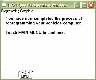
12 After locking to your vehicle the HyperPAC still has additional questions which must be answered to fully configure your HyperPAC. These are generally pieces of information which cannot be determined by reading the vehicle s VIN alone. Note that the specific screens displayed and questions asked will vary from vehicle to vehicle. Finally a summary screen will be displayed which shows the vehicle information. This is the final step in the initialization process. Touch MAKE CHANGES to update any of the vehicle information, or touch NEXT to complete the initial HyperPAC setup and go to the Main Menu. The HyperPAC setup is now complete and you are ready to begin enjoying all the features of your new HyperPAC. 12
13 This is the default screen which will be displayed each time you power up your HyperPAC. However, you can select another display to be the default screen. By entering the Gauges program and select one of the gauge displays this can now set a new default screen automatically. If you power off the unit at this point the current screen will become the new default screen which will be displayed at power up. So by selecting and configuring your selected screen from the Gauges program you can customize you HyperPAC to show any default screen you wish. Please see the Gauges chapter for details on these screens. 13

14 Possible Problems Encountered During Startup Deciding to NOT lock to a vehicle When you are asked to lock to this vehicle, if you choose CANCEL the following screens will be displayed. Since the HyperPAC has not yet locked to a vehicle it cannot perform any functions. You must repeat the startup process to lock to a vehicle. 14

15 Calibration Not Found When the HyperPAC unit locks to your vehicle it communicates with the vehicle s electronic control unit and reads the identification of the various calibration files contained within. This information is required by the HyperPAC to perform its Performance Tuning functions. In some cases however the HyperPAC might not recognize all the calibration files found. This can happen if the vehicle you are driving was produced after the HyperPAC was shipped from the factory. In this case the locking to the vehicle can still proceed and the following screen will be displayed. At this point you can continue to lock to the vehicle however the Performance Tuning functions will be temporarily disabled, but all other features will work. You will need to contact Hypertech in order to get an update to the tuning files in the HyperPAC. Hypertech will make an update available for you which contains the necessary tuning information. Please see the chapter in this manual about updating your HyperPAC. In the meantime you can continue with the remaining questions. When locking is complete you will see on the main menu that the Performance Tuning function is not available. 15
16 The next time you power up the HyperPAC you will be reminded that the calibration files are not supported with the following screen. Once you have obtained to correct calibration files from Hypertech this message will no longer be displayed and the Performance Tuning function will be made available. 16

17 Calibration files changed If you ever take your vehicle in to the dealer it is possible that they may update the tuning files in your vehicles computer. If this should occur than the tuning information you had loaded into the vehicle computer using the HyperPAC will be lost. When the HyperPAC next powers up it will detect that the tuning files have changed. At this point it could be in one of two states: either the new tuning files in your vehicle are recognized by the HyperPAC, or the new tuning files are not recognized. If the tuning files are recognized then the HyperPAC can simply reset its internal tables to reflect that the vehicle is now in a stock condition. The following screen will be displayed. In this case all tuning capabilities are still available. In order to reload your selected tuning options into your vehicle you must go back to the Performance Tuning program and make your selections and program the vehicle again. 17
18 Alternately the files loaded by your dealer might not be recognized by the HyperPAC. In this case the following screen will be displayed. This can occur in instances where the tuning file the dealer loaded was not known to Hypertech at the time of your HyperPAC s manufacture. In this case you will temporarily not be able to perform the Performance Tuning program. You must now contact Hypertech s customer service to obtain an update to your HyperPAC. You may be asked to go to the Calibration ID screen in order to tell Hypertech which calibration files are missing (see the Performance Tuning chapter for further details on this function). 18

19 Wrong Vehicle If your HyperPAC displays the following screen it indicates that the HyperPAC does not recognize some vital information about your vehicle. There are some common conditions which can cause this problem. The most common cause is that the HyperPAC is not for this particular make, model or year vehicle. The year is a particularly common mistake made. Please read the packing label carefully to be sure you have purchased the correct HyperPAC for your vehicle. There can be other causes however. There have been cases of unusual body style vehicles causing this error. For instance, some cab-on-chassis configurations might not have been fully configured in the HyperPAC software. It is possible some database files may be missing or not up to date. In many cases, if you have purchased the correct HyperPAC for your vehicle, this problem can be corrected with a simple update from Hypertech. Please contact our customer service department to resolve this issue. 19
20 Performance Tuning Program With the Performance Tuning program, you can optimize your engine s tuning as well as adjust other vehicle parameters, all at the touch of a button! With the performance tuning program, you can get more horsepower and torque for any kind of driving. For vehicles designed to run on regular octane, the HyperPAC features Hypertech s exclusive Dual Fuel tuning for regular and premium octane gasoline. In most vehicles, Hypertech s power tuning for regular octane produces virtually the same power gains as the premium octane tuning, saving you the difference at the gas pump. For diesels, Hypertech delivers the most powerful, safest, street-legal tuning for towing. This 3-Stage diesel tuning can be used at the maximum power setting when towing up to the vehicle s maximum weight rating, while maintaining safe critical exhaust gas temperatures (EGTs) and emissions. With HyperPAC you have complete freedom to select any or all tuning options for your vehicle. You can select whichever tuning options you desire and program them at any time. You can also program any individual or group of parameters back to stock while leaving others tuned. Plus, you have the ability to return all settings back to stock with a single option selection if you wish. HyperPAC tuning is designed to operate on vehicles whose computer is in stock condition. You should not attempt to program a vehicle that has already been programmed by another device! This stacking can result in unpredictable behavior which may damage your engine. Only load HyperPAC tuning into vehicles whose computer is in stock condition. However, if your vehicle does contain other after-market tuning you can still use all other HyperPAC features. The drag, dyno and gauge applications will still operate as intended on these vehicles. Read below to see the specific features you can change all at the touch of a button! 20
21 From the HyperPAC Main Menu, touch PERFORMANCE TUNING. 21


22 HyperPAC offers the ability to tune a wide variety of vehicle parameters and will only display the specific options available on your vehicle. Therefore your screens may look different to the ones shown here. In some cases there will be more options available than can be easily shown on a single screen. In these cases an arrow will appear on the right hand side of the screen. Touching this arrow will take you to additional programming options. Touch the item you wish to modify to see the possible tuning selections for this parameter. 22

23 Touch CURRENT SETTINGS to display a list of what is currently programmed in the vehicle s computer. The first time you connect the HyperPAC to the vehicle all performance settings are set to their stock value. Touch MAKE CHANGES to return to the Performance Tuning main menu and select the option that you wish to modify. 23

24 Engine Power Tuning Get more horsepower and torque for any kind of driving. For vehicles designed to run on regular octane, the HyperPAC features Hypertech s exclusive Dual Fuel tuning for regular and premium octane gasoline. In most vehicles, Hypertech s power tuning for regular octane produces virtually the same power gains as the premium octane tuning, saving you the difference at the gas pump. For diesels, Hypertech delivers the most powerful, safest, street-legal tuning for towing. This 3-Stage diesel tuning can be used at the maximum power setting when towing up to the vehicle s maximum weight rating, while maintaining safe critical exhaust gas temperatures (EGTs) and emissions. The Engine Power Tuning screen will display one of the following screens depending on your particular vehicle. Unique screens are presented for gasoline power vehicles, diesels, vehicle which can support various octane fuels and, in some cases, custom tuning is available for vehicles with aftermarket intake systems. The particular screen shown will depend upon what is supported on your particular vehicle. It will be similar to one of the following screen types. Tuning for gasoline engines which support multiple fuel grades Select the desired level of Power Tuning and touch ENTER. The most powerful 50-State, street legal engine tuning, Hypertech s exclusive Dual Fuel engine tuning for both regular and premium is available for vehicles that were originally designed to run on regular low octane fuel. Power Tuning for Regular should only be used with a minimum fuel rating of 87 octane. Hypertech Power Tuning for Premium should only be used with a minimum fuel rating of 93 octane. 24

25 Tuning for diesels Hypertech diesel tuning is offered in 3 different stages to match your individual driving styles, with Stage 3 providing the maximum Horsepower and Torque increases. All Hypertech Power Tuning is developed for the maximum towing weights allowed by the manufacturer. Refer to your vehicle s owner s manual for approved towing weights for your vehicle. 25


26 Tuning for custom aftermarket intake systems Hypertech also offers tuning specifically designed to work with particular intake systems. This custom tuning was performed on the vehicle using each of the indicated cold air intake systems. This tuning is also available in both the Dual Fuel levels. Select the fuel you wish to run and the intake system you have installed using the controls on this screen. Tuning for custom supercharger pulleys 26

27 Adjust RPM Rev Limiter The key to faster acceleration is to use more of your engine s horsepower. The HyperPAC lets you adjust your engine s rpm limiter to improve performance and driving fun. The stock computer is programmed to shut down the engine when it reaches the redline. But if you have modified your vehicle to increase its high-speed performance, more rpm means more power. When you shift gears at the stock rpm limit, the engine falls back to below the peak of its horsepower curve. When you extend the engine s rpm range with the HyperPAC, your engine has more power available after gear changes. And by keeping the engine in the sweet spot of its power curve, you can increase the average horsepower that accelerates the vehicle. Use the UP and DOWN arrows to increase or decrease your RPM rev limiter in 100 RPM increments. This will adjust the RPM at which the car computer will cut ignition or fuel. This setting is independent of a shift point selection and will affect the maximum engine revs in any gear. 27
 this produces a cooler, denser intake charge that allows the engine to make more power.")
28 Adjust Electric Cooling Fan Settings The HyperPAC also allows you to electronically adjust the on/off temperatures of your vehicle s electric cooling fans. When used with a Hypertech PowerStat (lowtemperature thermostat) this produces a cooler, denser intake charge that allows the engine to make more power. A cooler engine is also less likely to detonate under heavy loads. That means better performance for you and longer life for your engine. Installing a thermostat that opens/closes at a cooler temperature can eliminate or reduce harmful detonation under heavy load by letting the engine operate cooler. To take full advantage of a cooler thermostat the temperatures that the electric fans turn on and off at need to be adjusted to ensure that fresh air is being pumped across the radiator while the thermostat cycles open and closed. The HyperPAC will automatically adjust the vehicle's electric cooling fan on/off temperatures to match different thermostat temperature ratings. The electric cooling fan on/off temperatures can also be adjusted to allow cooler engine temperatures even with the factory installed thermostat. Select the temperature rating of the thermostat you have installed. 28

29 Adjust Transmission Shift Points You can adjust automatic transmission shift points for maximum performance for faster acceleration and better 1/4-mile times, as well as adjust the part-throttle shifting to work properly with non-stock tire sizes and/or non-stock rear gear ratios. If you ve installed taller or shorter tires or changed the rear gear ratio, the vehicle s onboard computer can t calculate speed correctly. It may signal the transmission to upshift too soon or to hold a gear too long. With the HyperPAC, you can customize the shift points for every gear. For vehicles with electronic transmission controls HyperPAC offers adjustments to the shift points. Shift points can be individually raised or lowered in each gear. The HyperPAC will display controls for the appropriate number of gears. Note that some transmission controllers determine shift points based on vehicle speed while others control it based on engine RPM. The controls presented will be configured based on your particular vehicle. Use these controls to raise or lower your shift points for each gear. Note If you are raising your shift points you must raise your Rev Limit accordingly! By raising your shift points without raising your rev limit you may enter a condition where you car will not shift because the required RPM cannot be reached. Always raise your rev limit by at least as much as you raise your shift points. 29

30 Adjust Transmission Shift Firmness You can electronically increase automatic transmission line pressure for firmer shifts while reducing clutch slippage and transmission oil temperatures. That means longer transmission life. The Shift Firmness feature increases the transmission line pressure to provide both a firmer and quicker shift to reduce clutch wear and slippage, and reduce transmission temperatures. This feature is for the factory equipped transmission and should NOT be used in conjunction with aftermarket shift kits or other transmission modifications. Failure to comply may result in damage to the transmission. Depending on your particular vehicle you will be offered different firmness options. Some vehicles allow for four different levels of firmness, where level 4 is the firmest and the others are less aggressive shift firmness settings. You can try each of them to see which setting best suits your needs. Alternately, your vehicle may only allow for one configuration other than stock. Select the desired level of shift firmness and touch ENTER. 30

31 31
32 Correct For Non-Stock Tires and Gears If you ve installed non-stock tire sizes or a different rear gear ratio, you must reprogram your vehicle s computer to correct speedometer/odometer readings and part-throttle shifting. The electronic brains in late-model vehicles are programmed to work properly only with the factory-installed tire size and rear gear ratio. If you ve installed taller or shorter tires or changed the rear gear ratio, the computer can t accurately determine the vehicle s speed. As a result, the automatic transmission may not shift correctly and the speedometer/odometer readings will not be accurate (as required by law). The HyperPAC lets you select different tire sizes and rear gear ratios, and then reprograms your vehicle s computer. Use this feature to calibrate your speedometer and odometer if you have changed the tire height or rear axle gear ratio. Not only will this correct the speedometer and odometer readings (as required by Federal Law), but it will also resynchronize transmission shift points for vehicles equipped with electronically controlled transmissions. The operation of these settings is the same as their operation if you selected these from the Vehicle/Owner Information Settings main menu item. Please refer to that section for details on how to operate these features. 32

33 Adjust Vehicle Top Speed Limiter Hypertech s HyperPAC lets you electronically adjust your vehicle s top-speed limiter to match the speed rating of factory-approved high-performance tires. The maximum speed of many modern vehicles is governed by the onboard computer. The stock computer is programmed to shut down the engine when the vehicle exceeds the speed rating of the original equipment tires. But if you have installed tires with a higher speed rating for offhighway competition in sanctioned events, your vehicle may be able to achieve a higher top-speed. A tire s maximum safe speed under perfect conditions is marked on its sidewall. Codes for popular high-performance tires are: T=118 mph, U=124 mph, H=130 mph, V=149 mph, Z=149+ mph This feature may only be used with Factory approved speed rated tires. Use the UP or DOWN arrows to select the speed rating of the tires installed on the vehicle. NOTE: Always obey Federal Traffic Laws. Do not raise the vehicle top speed limiter above the speed rating of the tires installed on the vehicle. Raising the vehicle top speed limiter above the speed rating of the tires installed on the vehicle may lead to a serious or fatal accident. 33

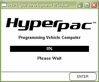
34 Programming New Changes From the Performance Tunings Main Menu, touch PROGRAM CHANGES to see a complete list of all of the changes before reprogramming the vehicle. IMPORTANT: -DO NOT leave the vehicle while programming is in process. -Make sure the vehicle battery is FULLY charged BEFORE programming. -DO NOT operate electrical accessories (radio, windows, wipers, etc.) while programming. -DO NOT attempt programming while the vehicle is connected to a battery charger. If you wish to make more changes before programming the vehicle, touch MAKE CHANGES. If all of the changes are correct touch START PROGRAMMING to begin the programming process. The HyperPAC will lead you through some simple instructions screens requiring you to cycle the ignition on and off, simply follow the instructions on the screen. These Instruction screens may vary depending upon Year, Make, & Model and are not shown in this manual. Whenever you are given instructions to turn the ignition on or off you must switch the ignition before touching the OK button. The programming process may fail if you do not follow the instructions exactly. NOTE: The programming process takes between one and 20 minutes. The vehicle s engine cannot be running during the programming process. Never leave the vehicle unattended during the programming process. 34

35 35

36 Returning The Vehicle To The Stock Program From the Performance Tuning s Main Menu, touch RETURN ALL SETTINGS TO STOCK. NOTE: All of the performance tuning features will be reset to the original stock program. The HyperPAC will lead you through some simple instructions screens requiring you to cycle the ignition on and off, simply follow the instructions on the screen. These Instruction screens may vary depending upon Year, Make, & Model and are not shown in this manual. NOTE: The programming process takes between one and 20 minutes. The vehicle s engine cannot be running during the programming process. Never leave the vehicle unattended during the programming process. 36

37 If you have started the Power Tuning program, make selections, and then attempt to exit the program then HyperPAC will warn you before allowing you to exit. If you meant to actually program these changes into the vehicle then touch NO and you will be returned into the program where you can now select Program Changes to begin the programming process. If you do leave the program without programming your selections then your selections will be discarded and must be entered again before they can be programmed. Note, that if you had made a change to tire size or gear ratio from the main Vehicle/Information Setup program then HyperPAC will consider this to be a request for a programming selection. When you next enter the Power Tuning program HyperPAC will keep track of this request and prompt you to program it before attempting to leave Power Tuning. 37
38 Drag Strip Program With a real Christmas Tree start, the Drag Strip program allows you to measure your vehicle s performance and produces an exact duplication of a drag strip time slip, with reaction times, 60ft, 330ft, 1/8 th mile, 1000ft, and ¼ mile speeds and E.T.s. In addition to getting all of the standard time slip information, every run automatically generates a magazine style Road Test with acceleration measurements of 0-10, 20, 30, and continuing in ten mile-per-hour increments until you let off the accelerator pedal. You also get a detailed Drive Wheel Horsepower chart and graph, and Data Acquisition report for each run to let you know what the vehicle s operating conditions were during the test. For convenience, each run is automatically named and saved so you can go back and review the results at anytime. 38
39 Creating New Test Sessions Enter the Drag Strip program from the HyperPAC Main Menu by touching the DRAG STRIP button. When you first enter the Drag Strip program from the Main Menu the following screen will be displayed allowing you to create new test sessions or review any saved test sessions. To begin a new test session, Touch CREATE NEW TEST SESSION and the HyperPAC automatically names the session with the current date and brings up a keyboard for entering session notes. 39
40 Explanation of how sessions and runs are named The HyperPAC groups and stores multiple runs within individual test sessions. Each test session is automatically named by the date it is performed on. Any additional sessions performed on the same day are indicated by the number that appears after the underscore on the far right-hand of the session name. (Session 01/01/2005_1 Run 1) indicates the first run of the first test session performed on January 1, (Session 01/01/2005_1 Run 2) indicates the second run of the first test session performed on January 1, (Session 01/01/2005_2 Run 1) indicates the first run of the second session performed on January 1, NOTE: The session name and run # will always be displayed in the upper right hand corner of the screen. SESSION NOTES When you first select Create New Test Session a keyboard is automatically displayed for entering session notes. You are not required to enter session notes and may choose to skip this process by simply touching ENTER. Session notes are for keeping track of information that will apply to ALL of the runs within the current session. This is the place to put information that will not change between runs. A good example of this would be entering the current configuration of your vehicle for that test day, example- new cold air kit, new headers, camshaft, etc Use the keyboard to type in the session notes and touch ENTER to proceed to the RUN SETUP screen. NOTE: You can touch ENTER without entering any notes and go straight to the Run Setup screen. RUN SETUP Screen 40
41 The Run Setup screen will always be displayed before making a Drag Strip or Dynamometer a run. This screen contains all of the information and settings that can effect horsepower and torque measurements. Run Notes Unlike session notes, the RUN NOTES window is used for entering data that may change for each individual run. An example of this would be things such as, the level of boost that you dialed in for the run, or how you launched the vehicle off of the line. Again, like session notes, it is not required to enter run notes and you can go straight to the Staging Lane by touching STAGE VEHICLE. Touch the Run Notes window to bring up the keyboard to enter run notes. NOTE: You can also go back after the run is finished and update the run notes to include information like a missed gear, etc 41

42 Change Setup For accurate horsepower and torque measurements, each of the settings shown under Current Setup must be entered correctly. These settings can be quickly updated before making a run by touching the CHANGE SETUP button. Touching the CHANGE SETUP button brings up a list of the parameters which you can set. Vehicle Weight Refers to the curb weight of the vehicle as it will be tested. This should include any additional weight for fuel, cargo, and the weight of any passengers. Most race tracks have scales to accurately measure the weight of the vehicle as it is to be tested, and this is the best way to ensure the highest level of accuracy. If you don t have access to heavy duty scales that are designed for weighing vehicles, you can obtain the vehicle s curb weight from the owner s manual or the vehicle manufacturer s website. You can estimate the weight of the fuel by using the following formulas: for regular octane fuel (6.216 x # of gallons), and for premium fuel use (6.350 x # of gallons). The vehicle weight is very important in determining the horsepower of the vehicle however; it has no impact on the elapsed time measurements. Tire Size and Gear Ratio The Tire Size and Gear Ratio settings should reflect what is currently installed on the vehicle. Tire Pressure refers to the current inflation pressure of the driving tires. Correction Factors Enter the correction factors to be used to correct the calculated horsepower and torque values. By default these are set to values which will yield no alteration to the horsepower for environmental correction. By setting these values to the prevailing conditions when you performed your run you will get more accurate and more repeatable horsepower readings. The values you enter here will be carried from run to run until you next change them. 42
43 If you ever wish to return to the default values which apply no correction simply return to this screen and touch Reset To STP. Relative Humidity is set to a default value of 0%. This can usually be obtained from the weather section of your local newspaper. Air Temperature indicates the current ambient (outside) temperature in degrees Fahrenheit or Celsius (the unit of measure is determined by the global setting in the vehicle/owner information). Barometric Pressure indicates the current Barometric Pressure as measured in inches of mercury or millibars. Drag Strip Setup Tree indicates the type of drag strip Christmas Tree that is currently selected. Choose between the standard Sportsman and Pro tree configurations. Both trees start with the first two yellow lights lighting 1 second apart. Then there will be about a two second delay. The Sportsman tree will then sequentially light then three main yellow lights at ½ second intervals, then light the green light. The Pro tree will light all three main yellow lights simultaneously and 4/10ths of a second later light the green light. Distance indicates the setting for a 1/8 th mile or ¼ mile drag strip. The HyperPAC will automatically sound a tone and show on the screen when you have traveled the selected distance. Accelerometer Sensitivity This setting provides a means of controlling the sensitivity of the HyperPAC for detecting the actual launch of your vehicle. In cars with a rough idle it is possible to falsely trigger the launch detection by the movement of the vehicle. Similarly, in vehicles that leave the line very gently it is possible the HyperPAC might fail to detect as soon as the vehicle begins to move. In either case, you can increase or decrease the sensitivity of the HyperPAC using this control. Configure Rollout This specifies the distance the vehicle must travel before the run officially begins. By default this distance is set to This distance reflects the length of the front tire as seen by the standard NHRA timing light located 1 9/16 above the ground. For the most accurate track simulation set this screen according to the actual dimensions of you tire. Or you can directly enter the rollout distance you wish to use. 43
44 Staging the vehicle and making a Run After verifying that all of your settings are correct touch STAGE VEHICLE to prepare to make a run. The Staging Lane screen will display a racetrack Christmas Tree on the right-hand side of the screen and the Engine Monitor will show important operating conditions on the left-hand side. The specific data shown on the left side of the screen will vary from vehicle to vehicle based on make, model, year and specific vehicle configuration. However, this data can be changed. Simply by touching any of the data items shown you will be taken to a list of all available data to monitor. Simply select the data item you wish to see from the list then touch OK, and that data item will be displayed in the selected display position. Please refer to the Gauges section for further details on this feature. 1. Bring the vehicle to a complete stop positioned on the starting line. With the brake pedal depressed, raise the engine RPM to the desired speed at which you want to leave the starting line. When you are staged and ready to make a run, touch START TREE. 2. The prestage light will come on (first small light). 3. One second later the stage light will come on (second small light). 4. For the next two seconds the HyperPAC will zero its accelerometers. If the vehicle is not completely stationary during this time invalid result will be generated. 5. If configured for the Sportsman tree audible tones will sound in 0.5 second intervals with each (yellow) light. The standard Sportsman tree is the 44
 light will come on as well. 7.")
45 default setting. If you select the Pro tree all three on simultaneously for 0.4 seconds. (yellow) lights will come 6. The left side (green) light will then be displayed and you can begin your run. The right hand (red) light will come on as well. 7. If you travel more than the rollout distance before the green light is displayed then you have jumped the start and the left hand red light will be displayed. Note you can still perform the run and get all the data as normal, but the reaction time will show a negative value. NOTE: For greater accuracy and consistency between runs use the Engine Monitor window to view the real-time data conditions to start each run with the same operating temperatures. If, at any time up until the car begins moving, you touch the ABORT RUN button then the run will be aborted and no data will be saved. No run will be considered to have taken place and there will be no record of the run in the log. Once the vehicle begins to move however there will be data created. Test in Process When you leave the starting line the HyperPAC will switch to a screen displaying the Engine Monitor readings and a large tachometer. 45
 mark, but the test results will not be")
. 2. Pressing the brake pedal 3. Touching the STOP RUN button.")
46 You may terminate the run by touching STOP RUN. The HyperPAC will sound a long tone once you reach the quarter-mile (or eighth-mile) mark, but the test results will not be displayed until the vehicle comes to a complete stop. A drag run can be terminated by any of the following conditions: 1. You travel the specified run length (1/4 or 1/8 th mile). 2. Pressing the brake pedal 3. Touching the STOP RUN button. Regardless of the reason for stopping the run the HyperPAC will always attempt to calculate data from the run. 46

47 47
48 Reviewing the test results During each run the HyperPAC records all of the data and automatically processes it into user-friendly reports so you can easily review the test results. NOTE: From any of the following report screens you can touch NEW RUN to exit and get ready for another run. All of the tests are automatically saved and can be viewed by selecting Viewed Saved Sessions from the Drag Strip program s main menu. This process will be explained in Viewing Saved Sessions. The Drag Time Slip is the first screen displayed after the vehicle comes to a complete stop. The HyperPAC time slip is an exact replica of a time-slip like you get at the track. It includes the reaction time and 60ft, 330ft, 1/8 th mile, 1000, and ¼ mile speeds and E.T.s. You can quickly view any of the other test results by touching a report button on the lefthand side of the display. The ROAD TEST report displays acceleration times in 10 mile-per-hour increments from 0 until you let off the gas. 48
 for ambient temperature,")

49 The DRIVE WHEEL HORSEPOWER report displays the horsepower at the rear wheels vs. vehicle speed. All of the results are corrected to the STP standard (Standard Temperature and Pressure) for ambient temperature, barometric pressure, and humidity. These correction factors came from the values entered in the Vehicle Setup prior to the run and are automatically applied for each run. Touch HORSEPOWER GRAPH to view the horsepower results in a graph format. 49

50 On this or any other graph displayed on HyperPAC you can zoom in to get a closer view on a particular region. To zoom in touch your finger to the lower left hand corner of the area you wish to zoom, and then drag your finger across the screen to the upper right hand point. Then release your finger from the screen and the HyperPAC will zoom in and rescale the image to the area requested. 50

51 If you wish you can zoom in again to get an even closer look. Alternately, you can simply touch a point on the screen and the HyperPAC will zoom in to that point. 51
52 When zoomed touching the BACK button will unzoom. Touch the BACK button to return the Horsepower table or select another report. Touch DATA ACQUISITION to see a report of the operating conditions recorded during the run. 52

53 Use the horizontal and vertical scroll bars to evaluate the operating conditions referenced to time during the run. Touch BACK to return to the other reports. NOTE: From any of the report screens you can touch RUN NOTES to add additional information, example: missed 2 nd gear or let out due to knock. 53

54 Viewing Saved Sessions From the Drag Strip program s main menu, Touch VIEW SAVED SESSIONS to display a list of the saved test sessions. A listing with all of the saved test sessions will be shown with the session name, number of runs within the session, and a snap shot of the session notes. Use the vertical scroll bar to highlight the session you wish to view and touch ENTER. The HyperPAC will display any additional session notes so you can see if you have selected the session you want to review. 54


55 Touch ENTER to proceed and view the test results for that session, or touch BACK to return to the list and select another test session. In the review mode, once you have selected a test session to review, the report screens operate just like they do in the active mode except the NEW RUN button has been replaced with a NEXT RUN button. When viewing any of the report screens, touch NEXT RUN to see the same report screen for the following run. Example If you made three runs in a test session and you are only interested in the time slip information, simply select the DRAG TIME SLIP report and then use the NEXT RUN button to jump to the time slip for the other runs within that session. The session ID and run number are located in the upper right hand corner of the screen to indicate which run is currently displayed. 55
56 View each of the other reports (Road Test, Drive Wheel Horsepower, & Data Acquisition) or touch END SESSION to return to the Drag Strip program s main menu. NOTE: The RUN NOTES may be updated in the review mode. Note that HyperPAC has recorded the vehicle and environmental setup for each run. Touch REVIEW SETUP to see the settings which applied to this run. 56

57 Deleting Saved Sessions You may delete sessions from the list by highlighting a test session and touching DELETE TEST. The screen will warn you that you are about to delete a test session and give you the option to CONTINUE or touch BACK to keep the session and return to the review list. 57
58 Using your HyperPAC at a race track While one of the main reasons the HyperPAC was developed was to provide drag strip and dynamometer test results for those people who do not have access to a race track or chassis dynamometer, using your HyperPAC at the drag strip allows you to conveniently save all of your run information and review it at a later date. In addition to the time slip information, you get all of the other information that the HyperPAC saves with each run, acceleration times, horsepower and torque readings, and a data acquisition report for the engine operating conditions recorded during the run. If you do choose to use the Drag Strip program of your HyperPAC at the track, follow the procedure for creating a new test session, and: 1. Touch STAGE VEHICLE on the HyperPAC and stage the vehicle based on staging lights on the race track s Christmas Tree. 2. Once you are properly staged, touch START TREE on the HyperPAC and ignore the HyperPAC 's "Christmas Tree, allowing it to drop to the green light. Do not allow the vehicle to move or you will start the HyperPAC trigger. 3. Watch the race track's "Christmas Tree and leave the starting line based upon its green light. When you finish the run, all of the data in the HyperPAC will be correct, except for the reaction time. If you wish keep track of your reaction times, use the run notes section to enter the reaction time from your track time slip for that run. Note: You have up to one minute after the HyperPAC goes green to leave, before the HyperPAC will time-out and abort the run. Calibrating the HyperPAC to the Drag Strip Time Clocks The HyperPAC produces results consistent with the average drag strip timing system. However, these results can vary slightly from any particular track, for either or both of two reasons. First, the NHRA & IHRA allow tracks some latitude when setting up the staging lights and the guard beam. And second, the true roll-out distance is affected by all of the following conditions; tire air pressure, the amount of tire wear, and slight variations in sidewall construction and dimensions (for tires of the same size but from different manufacturers). For these reasons, slightly different results may be observed from track to track, and from your HyperPAC to any particular track. If you regularly visit a drag strip, the HyperPAC contains a track calibration feature that allows you to calibrate the HyperPAC to your local track s timing set-up. To do this, you will need to make several consistent runs and enter the track times into your HyperPAC. You will then be able to perform the following calibration procedure to configure your HyperPAC for this particular track. After this calibration and on all subsequent runs, elapsed times and speeds displayed on your HyperPAC will agree very closely with the elapsed times and speeds recorded by the track s timing system. There may still be a few hundredths difference because the HyperPAC always begins each run 58
59 with a perfect shallow stage to greater than 1/1000-inch accuracy. Therefore, real life staging at the track will always vary by more than the HyperPAC. To recalibrate your HyperPAC to a particular drag strip, follow the steps below. 1. Select the Drag Strip program from the HyperPAC "Main Menu" and touch CREATE NEW TEST SESSION. 2. Carefully stage your vehicle as shallow as possible. If you bracket race and always deep stage, then stage as you would normally. However, since deep staging is not as precise as shallow staging, your calibration will not be quite as accurate. 3. Once you have properly staged, touch START TREE. Ignore the track Tree until after your HyperPAC Tree goes Green. Then, if the track Tree shows a green light, you may leave. If not, let it turn green and then leave. Don t worry about either red lights or slow reaction times when doing calibration runs. Reaction times and red lights do not affect elapsed times or speeds. You have up to one minute after the HyperPAC goes green to leave. If you do not leave before the HyperPAC times out, a "Run Error" screen will be displayed. Touch OK, then touch STAGE VEHICLE and you will be ready to start the tree again. NOTE: How many runs do you need for calibration? You can use just one run, but greater accuracy is achieved if you use as many runs as it takes to get at least three very consistent timing slips based on the 60-foot times and the 1/8- or ¼- mile elapsed times and speeds. If your car is not very consistent, you may calibrate using 4, 5 or 6 of your best runs, but 3 is usually enough. 4. After you have 3 or more consistent runs (or one run if that is what you choose to do), touch END SESSION and enter the Drag Strip review mode by touching VIEW SAVED SESSIONS. 5. Go to the session you just completed and select the first run you wish to use for track calibration. 6. Select the "Review Setup" screen for that run and touch TRACK CALIBRATION. 59
60 Touch REVIEW SETUP 7. The HyperPAC 's recorded 60-foot time will be displayed for that particular run, and a "Window for entering the track's 60'-foot time will be displayed. 60


61 8. Use the numeric keypad to enter the track's 60'-foot time FOR THAT PARTICULAR RUN and touch NEXT. 9. Continue in a similar fashion and enter all the track times as well as the speeds for that run at the 1/8th mile if on an 1/8 mile track, and at both the 1/8 and 1/4 mile if on a 1/4 mile track. In order to prevent data entry mistakes, the HyperPAC will alert you if the track data you are attempting to use does not seem to match the expected value. 10. Once all of the track data for that run has been entered, the HyperPAC will display a complete list of both the track and HyperPAC data for a final review. 11. If the data was entered correctly and you wish to use this data for the track calibration, select the Use this data check box then touch OK. If at any time in the future you wish to no longer use this time for a track calibration, return to this review 61
62 screen and uncheck the Use this data checkbox. After touching OK, the unit will return to the Run Setup screen. 12. If you intend to use only one run for your calibration, touch END SESSION. But if you are using more runs for calibration, touch NEXT RUN, then touch TRACK CALIBRATION, and keep repeating these procedures until all runs have been entered. When you are finished, touch END SESSION. 13. The track calibration is now automatically active and will take effect on all subsequent runs. 14. If at any time in the future, you wish to either remove this calibration or calibrate your HyperPAC to a different track, simply return to the calibration verification screen and un-check the Use this data check box for each run you entered during the calibration procedure. 15. This removes the track calibration, and you may recalibrate for a different track, if you choose. Unless or until you do a recalibration, all of your subsequent test results will be HyperPAC -based only. 62
63 How a Drag Strip starting line works A drag strip starting line contains two photo-electric beams positioned slightly above the track s surface and at some distance apart. These beams are referred to as the "pre-stage" and "stage" beams. The set of lights that a driver watches to know when to start a race is commonly referred to as a "Christmas Tree. The Christmas Tree contains lights to indicate when you have pre-staged and staged and has 5 additional lights; 3 yellow, 1 green, and 1 red. Each of the two lanes on the track has this set of lights. When your vehicle moves forward and the front tires interrupt the first beam, the pre-stage bulb on the track's "Christmas Tree comes on, just to alert you that you are approaching the second beam, the "Stage" beam. As you continue to slowly roll slowly forward, the front tires will block the Stage beam and the Stage light will come on, signaling that the vehicle is staged. The distance traveled from the point when the stage light comes on until the vehicle s front tires have cleared the stage beam is called "Roll Out". If you stop immediately at the point when the stage light just comes on, that is considered "shallow" staging. Shallow staging provides the most roll-out distance, which allows the vehicle to make a longer running start before starting the timing clocks, resulting in the quickest E.T.s and fastest speeds. If you move past the point where the stage light comes on, you are "Deep" staging. If you clear the stage beam before the tree begins, the stage light will turn off, and you are no longer staged. One method of deep staging is to move forward slowly until the prestage yellow light goes out, and stage at that point. Deep staging is only used by bracket racers to reduce their reaction times, but for quickest and fastest runs, always shallow stage. In general, most cars leave around the time the last yellow comes on, without red lighting. A "perfect" start is when you leave at just the right moment to clear the stage beam just as the green comes on, and that results in a.000 second reaction time. A reaction time less than.000 seconds is considered a red light. If you are getting reaction times of.100 to.300 seconds, you are "late" on the tree. The best racers practice to try for reaction times between.010 to.030 seconds. Even good racers will sometimes red light, and will occasionally "be late." Since the HyperPAC provides reaction times you can practice your starts on private property and in a safe place, to develop that skill. 63
64 Dynamometer Program The Dynamometer program calculates both horsepower and torque verses RPM at the engine as well as horsepower verses road speed at the driving wheels. The results are displayed in both table and graph format. All horsepower and torque measurements are automatically corrected to Standard temperature, and pressure (STP), allowing valid comparisons between test conducted under different atmospheric conditions or on different days. All data monitored during the run will be recorded for later viewing. Dynamometer tests must be performed on a straight, flat stretch of road. You must have enough room to come up to speed, perform the test and come to a stop safely to review your results. This dyno application is designed to perform single-gear dyno runs only. In vehicles equipped with automatic transmissions care must be taken to ensure the transmission does not shift during the test as this will give erroneous results. Enter the Dynamometer program from the HyperPAC Main Menu by simply touching the DYNAMOMETER button. 64
65 Creating New Dynamometer Test Sessions When you first enter the Dynamometer program from the Main Menu the following screen will be displayed allowing you to create new test sessions or review any saved test sessions. To begin a new test session, Touch CREATE NEW TEST SESSION and the HyperPAC automatically names the session by the current date and brings up a keyboard for entering session notes. NOTE: Refer to section XX on page XXX for a more detailed explanation of how sessions and runs are named. SESSION NOTES When you first select Create New Test Session a keyboard is automatically displayed for entering session notes. You are not required to enter session notes and may choose to skip this process by simply touching ENTER. Session notes are for keeping track of information that will apply to all of the runs within a session. This is the place to put information that will not change between runs. A good example of this would be entering the current configuration of your vehicle for that test day, new cold air kit, new headers, camshaft, etc 65

66 Use the keyboard to type in the session notes and touch ENTER to proceed to the RUN SETUP screen. NOTE: You can touch ENTER without entering any notes and go straight to the Run Setup screen. RUN SETUP The Run Setup screen will always be displayed before making a run. This screen contains all of the information and settings that can effect horsepower and torque measurements. Touch anywhere inside of the notes box to bring up the keyboard to enter Run Notes. 66
67 Change Setup Touch CHANGE SETUP and you will be shown a list of all the available parameters which can affect your horsepower measurements or to record specific run data. Touch the item you wish to change then touch ENTER. Vehicle Weight Refers to the curb weight of the vehicle as it will be tested. This should include any additional weight for fuel, cargo, and the weight of any passengers. Most race tracks have scales to accurately measure the weight of the vehicle as it is to be tested, and this is the best way to ensure the highest level of accuracy. If you don t have access to heavy duty scales that are designed for weighing vehicles, you can obtain the vehicle s curb weight from the owner s manual or the vehicle manufacturer s website. You can estimate the weight of the fuel by using the following formulas: for regular octane fuel (6.216 x # of gallons), and for premium fuel use (6.350 x # of gallons). 67
68 Tire Size and Gear Ratio The Tire Size and Gear Ratio settings should reflect what is currently installed on the vehicle. Tire Pressure refers to the current inflation pressure of the driving tires. Correction Factors Enter the correction factors to be used to correct the calculated horsepower and torque values. By default these are set to values which will yield no alteration to the horsepower for environmental correction. By setting these values to the prevailing conditions when you performed your run you will get more accurate and more repeatable horsepower readings. The values you enter here will be carried from run to run until you next change them. If you ever wish to return to the default values which apply no correction simply return to this screen and touch Reset To STP. Relative Humidity is set to a default value of 0%. This can usually be obtained from the weather section of your local newspaper. Air Temperature indicates the current ambient (outside) temperature in degrees Fahrenheit or Celsius (the unit of measure is determined by the global setting in the vehicle/owner information). Barometric Pressure indicates the current Barometric Pressure as measured in inches of mercury or millibars. When all of your settings are correct, Touch MAKE RUN to prepare to make a run. 68
69 Making A Run Before making a run the DYNO READY screen will display important engine operating conditions and a large tachometer. The specific data shown on the screen will vary from vehicle to vehicle based on make, model, year and specific vehicle configuration. However, this data can be changed. Simply by touching any of the data items shown, including the tachometer, you will be taken to a list of all available data to monitor. Simply select the data item you wish to see from the list then touch OK, and that data item will be displayed in the selected display position. Please refer to the Gauges section for further details on this feature. To perform a dyno run ensure all test conditions are set, and then bring the vehicle up to the desired starting speed in the gear in which you wish to make the run. Note that dyno runs are for a single gear only! Touch the START DYNO button. Allow just a moment for the data to start recording then begin the run. In vehicles with automatic transmissions be careful not to allow the transmission to shift up or down during the run. To end the run either touch STOP RUN or depress the brake pedal. 69
70 After the run ends the results will be displayed after the vehicle has come to a complete stop. 70

71 Reviewing the test results During each run the HyperPAC records all of the data and automatically processes it into user-friendly reports so you can easily review the test results. NOTE: From any of the following report screens you can touch NEW RUN to exit and get ready for another run. All of the tests are automatically saved and can be viewed by selecting Viewed Saved Sessions from the Dynamometer program s main menu. The Engine Horsepower report is first screen displayed when the vehicle comes to a complete stop. The Engine Horsepower and Torque are displayed in 100RPM increments. All of the results are corrected to the STP standard (Standard Temperature and Pressure) for ambient temperature, barometric pressure, and humidity. These correction factors came from the values entered in the Vehicle Setup prior to the run and are automatically applied for each run. Use the vertical scroll bar to view the horsepower results. Touch HORSEPOWER GRAPH to see the results in graph format. 71
72 On this or any other graph displayed on HyperPAC you can zoom in to get a closer view on a particular region. To zoom in touch your finger to the lower left hand corner of the area you wish to zoom, and then drag your finger across the screen to the upper right hand point. Then release your finger from the screen and the HyperPAC will zoom in and rescale the image to the area requested. If you wish you can zoom in again to get an even closer look. Alternately, you can simply touch a point on the screen and the HyperPAC will zoom in to that point. 72


73 When zoomed touching the BACK button will unzoom. Touch BACK to return to the horsepower chart and select another report. Touch DRIVE WHEEL HORSEPOWER to view the calculated horsepower at the drive wheels in 10MPH increments. Drive Wheel Horsepower is also correct with the correction factors. Touch HORSEPOWER GRAPH to see the results in graph format. 73


74 Note that zooming is also allowed on this graph. Touch DATA ACQUISITION to see a report of the operating conditions recorded during the run. Use the horizontal and vertical scroll bars to evaluate the operating conditions based on time index into the run NOTE: From any of the report screens you can touch RUN NOTES to add additional information such as, missed 2 nd gear or let out due to knock. 74
75 Viewing Saved Dynamometer Sessions From the Drag Strip program s main menu, Touch VIEW SAVED SESSIONS to display a list of the saved test sessions. A listing with all of the saved test sessions will be shown with the session name, number of runs within the session, and a snap shot of the session notes. Use the vertical scroll bar to find the session you wish to view, select the session and touch ENTER. 75
76 The HyperPAC will display any additional session notes so you can see if you have selected the session you want to review. Touch ENTER to proceed and view the test results for that session, or touch BACK to return to the list and select another test session. In the review mode, once you have selected a test session to review the report screens operate just like they do in the active mode except the NEW RUN button has been replaced with a NEXT RUN button. When viewing any of the report screens, touch NEXT RUN to see the same report screen for the following run. Example If you made three runs in a test session and are only interested in the engine horsepower, simply select the ENGINE HORSEPOWER report and then use the NEXT RUN button to jump to the engine horsepower results for the other runs within that session. The session ID and run number are located in the upper right hand corner of the screen. 76

77 View each of the other reports (Engine Horsepower & Data Acquisition) in the same way, or touch END SESSION to return to the Dynamometer program s main menu. NOTE: The RUN NOTES can be updated in the review mode. Note that HyperPAC has recorded the vehicle and environmental setup for each run. Touch REVIEW SETUP to see the settings which applied to this run. 77


78 Deleting Saved Sessions You may delete sessions by highlighting a test session and touching DELETE TEST. The screen will warn you that you are about to delete a test session and give you the option to CONTINUE or touch BACK to keep the session and return to the review list. 78
79 Gauges Program The GAUGES program is a very powerful tool. It allows you to display and record your vehicle s sensor data in real time. This program can be used to help diagnose or troubleshoot problems. It can also be used when tuning or adding mods to your vehicle. HyperPAC has the ability to display your vehicle data in a wide variety of display formats. Analog format resembles that of a traditional gauge assembly found in most vehicles. The analog format includes full, ½, or ¼ style analog gauges. The digital displays show the current input value in numeric format. HyperPAC offers several different displays with large numbers for easy reading or smaller displays to view as many vehicle data elements as possible. The digital list format is a list of up to 14 inputs and their numerical values. The strip chart format resembles what you would expect to see on an oscilloscope, where the y axis represents the sensor value and the x axis represents time. The bar graph format represents the sensor simply as a bar. The Gauges program will record peak data values of any data item being monitored. These peaks are being recorded whenever a data item id being displayed in Gauges, Drag or Dyno programs. HyperPAC also provides and audible and visible alarm whenever any monitored data item exceeds thresholds which you select. HyperPAC will also remember the last gauge screen when you power off the unit and automatically return to that screen the next time you power up. Simply be on any of the Gauge screens when you press the power button to power down the unit and the HyperPAC will store that selection in its memory. You will be returned to that screen automatically the next time you power up. 79


80 To enter the Gauges program touch GAUGES on the HyperPAC Main Menu. You will then be shown graphical icons representing the various formats of gauge displays. Touch the arrows on the sides of the screen to page through the various displays to choose the one you wish to see. 80

81 Touch any one of the icons to bring up a display of vehicle sensor data. The sensors that appear are the current defaults for that particular window. However, it is entirely up to you as to which sensors you wish to view. 81

82 Changing Data To view a different sensor, just touch a sensor you wish to change. This will bring up the SELECT VEHICLE DATA window. This window lists all of the available sensors for your vehicle. Use the arrows on the right to scroll through the list. Sensors with a check mark beside them are being displayed in the current Gauges window. Select a sensor by touching it and then touching OK. This will replace the sensor you touched from the previous window. The sensor you just selected is now a default for this gauge view screen. 82
83 Configuring Data You can change settings for each sensor by first touching the sensor to bring up the Select Vehicle Data window. Then touch the CONFIGURE button to access the VEHICLE DATA CONFIGURATION window. In this window you can make a variety of changes to the sensor display. You can change the Gauge min/max Range, Alarm upper/lower Thresholds, and the Redline value. You can also choose to active/deactivate the Alarm or enable/disable the Redline. To make a change, touch the box enclosing the value you want to change. A keyboard will appear, allowing you to make the changes. 83
84 Now the display will have a new range. Enabling the Redline will show a broad line on an analog gauge beginning at the Redline value and continuing through the remaining range of the gauge just as an analog gauge inside a vehicle. 84

85 85

86 Review Peak Values The REVIEW PEAK VALUES feature stores the highest value recorded by any sensor that has been displayed (i.e. Gauges, Drag, or Dyno). These values are only updated when the sensor is actually being displayed. To access this feature, touch REVIEW PEAK VALUES in the GAUGES program. This brings you to the Peak Data Values window, where you can scroll through a list to view the peak values stored for each sensor. These values will remain in memory on the HyperPAC until you clear them. You can clear the peaks individually by selecting the sensor and then touching CLEAR INDIVIDUAL PEAK. You can also clear all peaks by only touching CLEAR ALL PEAKS. 86


87 Recording Data This feature allows the user to record sensor data. You can record up to 2 minutes of data at 5 samples per second. All displayed data will be recorded, so the particular items recorded will depend on the display you choose and the items you choose to have on that display. Touch START RECORDING and a new session will be created with today s date and the displayed vehicle data will be recorded. All recording sessions will record for a maximum of 2 minutes at 5 samples per second. If you wish to stop recording before the two minutes you can end it at any time by touching STOP RECORDING. 87

88 Reviewing Saved Data To review saved data tests, touch the REVIEW SAVED TESTS button from the Gauges window (scroll to the last page in the Gauges window). This will open the Data Acquisition Select Test window, which is a list of all saved data tests. In order to view a test, select the test name and touch ENTER. This opens the saved sensor data in table format. Vehicle sensor data is recorded 5 times per second. Note that the time stamps do not necessarily fall exactly on 0.2 second intervals due to processing overhead retrieving sensor data. Recording sessions are limited to a maximum duration of 2 minutes. Vehicle speed, RPM and brake pedal are all automatically added to any list of vehicle data since they are always being monitored by the HyperPAC. If you do not wish to see this data simply touch the scroll bar to shift your view to the right to the additional data. Scroll across to view all sensors recorded and down to review all values recorded for those sensors. To view test notes, touch TEST NOTES in the Data Acquisition window. To view the next test, touch NEXT TEST. 88


89 89
90 Deleting a Test To delete a test, select the test from the Data Acquisition Select Test window and touch DELETE TEST. This opens the Delete Test Session window. Touch CONTINUE to delete the test, or BACK to save and return to the review list. 90


91 Additional Features Analog Tattle Tail Needle All large full or ½ size analog gauges are equipped with a tattle tail needle that temporarily holds the highest sensor value for approximately 3 seconds. Strip Chart Pause Strip charts can be paused at any time during a data stream session. Touch the PAUSE button to pause the strip chart. When you touch the RESUME button, the strip chart will immediately resume streaming data in real time. 91
92 Alarms HyperPAC has the ability to sound an audible alarm on any vehicle data that is being monitored. The alarm is set from the Vehicle Data Configuration screen. Once armed the alarm will be triggered any time the vehicle data exceeds the maximum or minimum thresholds. When it is triggered and audible tone will be sounded and a message window will pop up. While the alarm condition is active and the alarm is sounding the out-of-range value is displayed in the warning window. The value displayed will be updated with the out of range value until either the window is closed by the user or the monitored data returns to a value within the acceptable range. If the value returns to acceptable levels then the window will remain displayed and the alarm sounding but the value in the window will reflect the last illegal value the system observed. HyperPAC alarms can be used for any monitored data, whether that data comes from the vehicle or from an optional HyperPAC module. The operation of the alarms is identical in either case. The alarm settings are global, meaning that the alarm thresholds and settings apply to all three main applications: Gauges, Drag and Dyno. Alarms set in one are also active in the other. Note however that alarms will only be active while the specific vehicle data is being displayed. So, while you are in the main menu, Diagnostics or Performance Tuning applications the alarms are not active. 92

93 Configuring Alarms To configure an alarm go to the vehicle data configuration screen by touching the particular data item on any of the displays. By default, all alarms are configured off when the HyperPAC ships. To activate an alarm touch the ACTIVATE ALARM checkbox. 93

94 To set the thresholds, touch the Upper or Lower Alarm Threshold values and enter your desired thresholds. Note that both upper and lower will be active at the same time. If one of the values is of no consequence, for instance the lower value of the engine coolant temperature, simply leave the setting at an exceedingly low value. 94

95 When you are ready touch OK. You will return to the vehicle data selection list. Notice now however that there is a Bell Icon displayed next to the name. This is an indication that an alarm is active on this data element. Touching OK will return you to the vehicle data monitoring screen and the alarm will now be active. 95

96 Alarm Action When the alarm threshold is exceeded the alarm window will display and the illegal value will be shown on the window. Again, the value shown will be updated as long as the alarm value is beyond the set limits. To remove the window touch CLEAR. WARNING: The alarm display will only be shown once for each time the alarm condition is exceeded. If you clear the alarm window while the alarm condition still persists you will not be notified again even though you are still exceeding the alarm condition! However, if the value returns to within the acceptable range and then subsequently exceeds the alarm condition again, then the alarm will be sounded again. 96

97 If you go to a different screen where this vehicle data is not being monitored then the alarm will not be active on that screen. This will be shown to you when you are in the vehicle data selection screen by the alarm bell being grey. This is the indication that there is an alarm selected for this data item but the data item is not currently being displayed. To enable the alarm on this screen you must select this data item as one of the items shown on this screen. 97

98 Diagnostics Program The Diagnostics program allows you to read and clear Diagnostic Trouble Codes (DTCs). The program not only displays the code, but it also gives you a description of what the code means. Use the Diagnostic program to trouble shoot problems and clear any codes after making the necessary repairs. Clearing the codes will also turn off any check engine lights that may have been triggered during the failure. Enter the Diagnostic program from the HyperPAC s Main Menu by touching DIAGNOSTICS. If the HyperPAC detects any codes it will display all the codes read one at a time. 98


99 If multiple codes are found, the display will show 1 of x trouble codes found. Touch NEXT to see the other codes. Touch CLEAR to clear all of the DTCs. The clearing process will not allow you to clear individual codes. This is a limitation of the vehicle s computer, not the HyperPAC. It s always a good idea to write down the codes and their information for future reference. The screen will notify you that all of the codes are about to be cleared. Touch BACK if you wish to keep the codes without clearing them. If there are no DTCs presently active in the PCM the screen will read No Diagnostic Trouble Codes Found. 99

100 Vehicle/Owner Information The vehicle/owner Information program gives you the ability to review or configure various overall settings for the HyperPAC such as display settings, volume, basic vehicle information, etc. These items can be changed at any time. Touch Screen Alignment HyperPACs are shipped without aligning the touch screen. This is left so that it can be tailored to the individual preference of the user. By touching the targets on these two screens the alignment will be set. Remember, if you decide later that you would like to change this setting you can come back to this screen and realign the screen at any time. 100
101 101

102 Display Settings The HyperPAC maintains two sets of display settings; one for day and another for night time viewing. You will notice that a setting which is appropriate for daylight viewing is much too bright for nighttime viewing. We have provided default settings for you for both. The last setting viewed with this screen will be the setting that will be used until it is manually changed. While running the HyperPAC you can change between day and night settings at any time by pressing the power key for ½ second. Adjust the display brightness and contrast by moving the slider bar to the right or left. You may also set the display to be White text with a Blue background (Blue on White not checked) or Blue text with a White background (Blue on White checked). Most people may prefer to use the white background during the day and the blue background during the night. Be sure to toggle between Day and Night to set both settings. Exit the screen with the settings you wish to use at the time as the current selection. Touch ENTER after making display adjustments. 102


103 Setting the time and date The HyperPAC maintains a time of day clock with is maintained even when the HyperPAC is powered off or disconnect from the vehicle. The time and date are used by the HyperPAC to name sessions and timestamp runs for your records. Use the up and down arrows to set the current time of day and select AM or PM. Every test that you perform will be automatically time-stamped with the current time and date. Touching ENTER will set the hours and minutes and zero the seconds, touching SKIP or BACK will exit the screen without changing the time at all. Similarly the date screen is used to set the month, day and year. HyperPAC does not know about leap years or daylight savings time so be aware of this. 103

104 Owner Name Use the keyboard to enter your user/owner name, and Touch ENTER to continue. 104

105 Unit of Measure HyperPAC can display its monitored data in either British Standard Units or metric units. You can switch at any time to see data in either format. All gauges and digital displays will follow this setting. Select the unit of measure for all displays and touch ENTER to continue. 105

106 Transmission Type Selecting between automatic or manual transmission configures the HyperPAC to know what data is valid for your vehicle. The transmission in your vehicle cannot be determined from the VIN and must be entered manually. When you go to one of the Gauges screens then the list of supported data items will reflect the setting made here. Note that if you configure the HyperPAC for automatic when the vehicle is equipped with a manual transmission an error message will be display when attempting to monitor data in the Gauges program. The transmission setting is also used for determining the appropriate drag coefficients as well as power correction factors for determining estimated engine horsepower and torque. 106

107 Tire Size HyperPAC can correct the vehicle speedometer for changes to the vehicle s gear ratios and tire sizes. To perform this correction the HyperPAC needs to know both the original settings as well as the new settings. In some vehicles this correction can also be programmed into the vehicle s computer so the vehicle speedometer reads correctly. But even without programming the vehicle s computer the HyperPAC must correct the speed readings for its own measurements in order to give correct horsepower and torque readings. You should ONLY answer yes to this question if you have changed the tire size on your vehicle from what it originally came with from the manufacturer. NOTE: The original equipment tire size can be found on the label in the driver-side door jamb. Verify that the size shown on the label is the same as what is printed on the sidewall of the tires installed on the vehicle. 107

108 First, use the up and down arrows to enter the Original Equipment Tire Size as shown on the label in the driver-side door jamb. You can either enter the tire size from the size written on the tire or you can measure the actual height of the tire. Entering tire height should be to the nearest ¼ inch or 5mm. Touch ENTER after making all selections. Second, use the up and down arrows to enter the New Tire Size as shown on the sidewall of the tires that are currently installed on the vehicle. Touch ENTER after making all selections. Once you enter a new tire size the HyperPAC will begin correcting the vehicle speed readings immediately. All drag, dyno and gauge functions will reflect this setting. However, the vehicle speedometer will not be corrected for this change until the vehicle is programmed with the correction from within the Performance Tuning program. 108

109 Note that when you enter the new tire size you might see a warning stating that the new tire height is out of range. This can happen on vehicles whose computer can only handle tire heights within a certain range. In this case the following screen will be displayed. The HyperPAC can correct vehicle speed measurement for any tire height you can enter. However, your vehicle s computer can only be programmed to correct the vehicle speedometer for a certain range. If you see this display then you cannot fully correct your vehicle s speedometer for these tires. You can, however, program the vehicle for the closest allowable setting as shown on the warning screen and then use the HyperPAC to correct the rest. 109

110 Gear Ratio For the HyperPAC to generate accurate test results the unit must be programmed for the correct rear axle Gear Ratio. You should ONLY answer yes to this question if you have changed the rear axle gear ratio on your vehicle from what it originally came with from the manufacturer. First, use the up and down arrows to enter the Original Gear Ratio as shown on the label in the driver-side door jamb. Touch ENTER after making all selections. 110
111 Second, use the up and down arrows to enter the New Gear Ratio currently installed on the vehicle. Touch ENTER after making all selections. Once you enter a gear ratio the HyperPAC will begin correcting the vehicle speed readings immediately. All drag, dyno and gauge functions will reflect this setting. However, the vehicle speedometer will not be corrected for this change until the vehicle is programmed with the correction from within the Performance Tuning program. 111

112 Vehicle Weight The vehicle weight is used to calculate Horsepower and Torque and therefore it must be entered correctly to provide accurate test results. Although, it has no impact on the elapsed time measurements during the drag runs. Vehicle Weight refers to the curb weight of the vehicle as it will be tested. This is not only the weight of the vehicle alone, but should also include any additional weight for fuel, cargo, and the weight of any passengers that are present during a Drag Strip or Dynamometer test. The default weight provided by the HyperPAC is an estimated curb weight of the vehicle with a passenger in every seat. Your nearest race tracks should have scales to accurately measure the weight of the vehicle as it is to be tested. This is the best way to ensure the highest level of accuracy, but you can obtain the vehicle s curb weight from the owner s manual or internet and then add the weight of any passengers, fuel, and cargo. On average gasoline fuel weighs 6.2 lbs. per gallon, so keep this in mind when calculating your vehicle s overall weight. If you make any changes to the vehicle remember to adjust the vehicle weight setting to maintain the highest level of accuracy. 112

113 Vehicle Information Summary This screen will show you a summary of the information and settings gathered during the initialization process. 113

114 Scanning for new modules HyperPAC supports several external modules for monitoring additional vehicle data such as exhaust gas temperature, transmission fluid temperature and air/fuel ratio. Version 3 application software supports a single module with its optional additional sensor. Version 4 and later support at least 8 modules. Each module will come with its own instructions (or you will find the instructions on this CD). But an overview is provided here. Please refer to the modules instructions for specific instructions on installing that particular module or sensor. From the Main Menu select Vehicle/Owner Information. Then scroll down to the item for Install New Modules or Sensors, select it and touch ENTER. Before any modules are installed the only option available is Scan for New Modules. Note that before you proceed with the scan the module must be installed in the vehicle and connected to the HyperPAC. Power must be on and provided to the module. When ready, touch Scan For New Modules. 114


115 This process will take a few seconds. Once the scan is complete the HyperPAC will display the list of all new modules that were detected. Note that several modules can be scanned in at the same time. Also note that once a module has been scanned it will not show up on future scans for new modules. It will only be displayed on the Review Modules screen. 115

116 At this point the module is installed and ready to use. However, this is a convenient time for you to customize the displays for this module. Specifically, since some of the modules are generic in nature, such as temperature probes, you can now issue a name for the module specific for how you have it installed. Once you have configured the module the installation is complete. However, the data for the module must be manually added to any Gauge or Drag/Dyno screen. This is done by simply touching the face of the gauge you wish to modify and selecting the module from the list of data items presented. The next time you enter the Install New Modules or Sensors screen you will have the additional options shown below. 116

117 The following operations are now supported: Review/Configure Current Modules o This function presents a list of all currently installed modules and sensors and allows you to edit the names, scales and alarm settings for these inputs. Scan For New Modules o This will scan for any new module. Note that currently installed modules will not be displayed. Install Additional Sensor on Current Module o EGT and Air/Fuel Ratio modules can support two sensors. The module is sold with once sensor, the second sensor is sold separately. If you purchased an additional sensor select this function to begin its install process. Note that only modules which can accept second sensors will be listed. Remove all Modules o Select this to start over with your module installation. You might want to use this if you purchase additional modules and you fear you have a switch setting conflict. You can set the module switches to unique values and reinstall the modules. Note that any second sensor installations will also be removed by this process so be sure to keep a record of the authentication code used when the sensor was first installed. 117

118 Software Version Number The versions of all the software components that make up the HyperPAC can be viewed on this screen. Should it ever be necessary to call Hypertech for information or service on your HyperPAC unit this information may be helpful to the service technician to diagnose a problem. They may ask you to tell them one or more of the version numbers displayed on the screen. 118

119 Setting Volume HyperPAC will make warning or announcement tones at various times during its normal operation. For instance, a sound is made to alert the user that he has completed traveling ¼ mile during a drag run. HyperPAC will also sound a warning tone when an alarm condition is triggered. The volume of these tones can be set from this screen. To hear a sample tone played at the currently selected volume level touch the TEST button. To adjust to a new volume level touch the control bar and slide it to the left to make the tone quieter or to the right to make it louder. 119

120 Current Tuning Selections Any time you wish to review your current tuning selections you can go to the Vehicle/Owner Information program and scroll down and select Current Tuning Selections. This will show you all the settings you have selected for your vehicle at the current time. When the vehicle is in a fully stock condition (no tuning options loaded) all these items will display Stock. 120
121 Calibration IDs When the HyperPAC unit locked to your vehicle it communicated with the vehicle s electronic control unit and read the identification of the various calibration files contained within. This information is required by the HyperPAC to perform its power tuning functions. To access this information you must start from the Main Menu and then go into Vehicle/Owner Information. Scroll down to near the bottom and find Calibration IDs, select this and touch ENTER. This will display the names of all the calibrations from your vehicle. 121

122 Calibration Not Found / Reading Calibration Files When the HyperPAC locks to your vehicle, or after you take your vehicle in for service, there may be cases where some of the calibration tuning files are not recognized. This can happen if the tuning files in your computer were produced after the HyperPAC was shipped from the factory. In this case the HyperPAC will have found a calibration in your vehicle but did not find a matching calibration in the HyperPAC s internal databases. In this case a screen similar to the one below will be displayed. If this is the case then you will need an update to your calibration files within the HyperPAC before the HyperPAC can program your vehicle. You will need to contact Hypertech customer service and obtain an update to your HyperPAC. When you contact the Hypertech customer service representative he may ask you to go to this screen and tell him which calibrations are listed as NOT FOUND. This will help him to determine which calibration files are missing from your unit. Hypertech will then arrange for you to get the necessary update. See section on updating your HyperPAC. There may be cases where Hypertech may ask you at have the HyperPAC read the calibration files out of your vehicle. After they have been read then Hypertech will obtain them from you (via either an internet download or by having the unit returned to Hypertech) and use these files to generate the missing calibrations you require. To perform the calibration file read return to this screen and touch the READ CALS button. HyperPAC will then display the following screens as it reads the calibrations. 122


123 Note that during the process of reading it may be required to cycle the vehicle ignition. Simply follow the instructions displayed on the screens. The calibration files will now be read and are ready to be sent in to Hypertech. After Hypertech updates them you will receive an update to your HyperPAC and you will then be able to program your vehicle. See section on updating your HyperPAC. 123
124 Accelerometer Calibration The Accelerometer Calibration feature is for use by authorized technicians to recalibrate the accelerometer in the HyperPAC. It is important that this be done accurately as the performance measurement capabilities of the HyperPAC utilize the accelerometer. This process is there to essentially teach the HyperPAC to orient itself in 3-dimensional space. The process takes the operator through a series of screens where the HyperPAC itself must be oriented in various positions and then a measurement process performed. This process is performed at Hypertech production facilities and should not need to be performed by an owner. It is recommended you CANCEL out of this procedure. 124

125 125

126 Updating Your HyperPAC The most common reason to need to update your HyperPAC is the case of calibration files not being found. This happens when the tuning files in your vehicle are not found in the tuning files in the HyperPAC s memory. This situation is common and is easily rectified by getting new tuning files for your HyperPAC. Other reasons you might need to update your HyperPAC would be to obtain new or additional features released after the production date of your HyperPAC. Or, in some cases, there might be errors in the code or tuning files of your HyperPAC which have since been fixed by Hypertech and are available as updates. Update Using SD Card After calling Hypertech with your need for an update an SD card will be mailed to you. To use this SD card simply power up your HyperPAC either in the vehicle or while connected to a wall-mount power supply. Once the HyperPAC comes to the main menu, shown below, insert the SD card into the slot at the bottom of the unit. After a few moments the following screen will appear. 126

127 Touch Yes to begin the update process, No will return you to normal operation. After touching Yes the code update process will begin. Depending on the number and size of the files being updated this can take anywhere from a few seconds to about 10 minutes. DO NOT remove the SD card from the slot at any point during the update process or damage to the files may result. The code update application will show you its progress as it goes. Wait until the screen shows CODE UPDATE COMPLETE before removing the card. Once this is displayed remove the card and power off the unit. When you power up the new files will be in use. 127
HyperPAC User Manual
 User Manual Welcome and thank you for purchasing the HyperPAC You are now the owner of the world s first Performance Automotive Computer, packed with FIVE distinct programs Performance Tuning, Drag Strip,
Reference Guide and Step-by-Step Installation Manual
 Reference Guide and Step-by-Step Installation Manual Some adjustable features listed on the following pages are NOT applicable for all applications. The year, make, and model of the vehicle will determine
DRIVE MODE SUPPLEMENT
 DRIVE MODE SUPPLEMENT DRIVE MODE SUPPLEMENT DODGE DRIVE MODES...3 SRT DRIVE MODES...33 DODGE DRIVE MODES SECTION TABLE OF CONTENTS PAGE 1 UNDERSTANDING YOUR INSTRUMENT PANEL...7 1 UNDERSTANDING YOUR
Part # FORD F L EcoBoost Reference Guide and Step by Step Installation Manual
 Part #2000 2015-2016 FORD F-150 3.5L EcoBoost Reference Guide and Step by Step Installation Manual Table of Contents SECTION 1: PROGRAMMING INSTRUCTIONS... 3 1-1: MAIN MENU... 4 1-2: TUNING MENU... 5 Suggested
DRIVE MODE SUPPLEMENT
 DRIVE MODE SUPPLEMENT DRIVE MODE SUPPLEMENT DODGE DRIVE MODES...3 SRT DRIVE MODES...29 DODGE DRIVE MODES SECTION TABLE OF CONTENTS PAGE 1 UNDERSTANDING YOUR INSTRUMENT PANEL...7 UNDERSTANDING YOUR INSTRUMENT
Ford Gasoline Speedo-Pro Programmer. Reprogram. Power
 Ford Gasoline Speedo-Pro Programmer 4 Reprogram Power INSTALLATION INSTRUCTIONS OVERVIEW Your vehicle has an onboard computer that controls the engine and transmission. The JET programmer reprograms your
Dynojet Research, Inc. All Rights Reserved. Optical RPM Sensor Installation Guide.
 1993-2001 Dynojet Research, Inc. All Rights Reserved.. This manual is copyrighted by Dynojet Research, Inc., hereafter referred to as Dynojet, and all rights are reserved. This manual, as well as the software
Power. Reprogram. GM Truck 4.3L, 5.0L, 5.7L, 7.4L
 Performance PROGRAMMER GM Truck 4.3L, 5.0L, 5.7L, 7.4L 4 Reprogram JET Performance Products 17491 Apex Circle, Huntington Beach, CA 92647 (714) 848-5515 Fax: (714) 847-6290 Power 2012 JET Performance Products
Power. Reprogram. JET Performance Products Apex Circle, Huntington Beach, CA (714) Fax: (714)
 Fax: (714)") Performance PROGRAMMER GM Truck 4.8L, 5.3L, 6.0L & 8.1L WARNING:Failure to read and follow instructions may result in damage to your vehicle. Please read and follow the instructions before attempting to
Performance PROGRAMMER GM Truck 4.8L, 5.3L, 6.0L & 8.1L WARNING:Failure to read and follow instructions may result in damage to your vehicle. Please read and follow the instructions before attempting to
CUSTOMER INSTRUCTIONS v2.0
 CUSTOMER INSTRUCTIONS v2.0 Thank you for purchasing the Ford Racing TracKey (Ford Racing part number M-14204- MBTKA) for your 2012 or 2013 Boss 302. This document describes how to use the features that
Part #2000/2100 Reference Guide and Step by Step Installation Manual Performance Chips & Programmers
 Part #2000/2100 Reference Guide and Step by Step Installation Manual Performance Chips & Programmers PLEASE READ BEFORE USING PROGRAMMER! The installation process is very easy and should not take long
MODEL MCL-3212 SPEEDOMETER/TACHOMETER for 2012 up Dyna and Softail with 4 gauge
 MODEL MCL-3212 SPEEDOMETER/TACHOMETER for 2012 up Dyna and Softail with 4 gauge IMPORTANT NOTE! This gauge has an odometer preset option that is only available one time in the first 100 miles (160km) of
MODEL MCL /8 SPEEDOMETER/TACHOMETER for 2004 up
 MODEL MCL-3204 3-3/8 SPEEDOMETER/TACHOMETER for 2004 up IMPORTANT NOTE! This gauge has an odometer preset option that is only available one time in the first 100 miles (160km) of operation. See Odometer
Owner smanual Banks OttoMind Programmer
 with Installation Instructions Owner smanual Banks OttoMind Programmer w/economind Features 01-07 GM 8.1L Workhorse Class-A Motor Home 99-07 4.8L, 5.3L, 6.0L, 8.1L Trucks THIS MANUAL IS FOR USE WITH P/N
Power. Reprogram. Ford Gasoline E-Z TUNE Programmer
 Ford Gasoline E-Z TUNE Programmer 4 Reprogram JET Performance Products 17491 Apex Circle, Huntington Beach, CA 92647 (714) 848-5515 Fax: (714) 847-6290 Power 2010 JET Performance Products JET P/N 16-300
NO PART OF THIS DOCUMENT MAY BE REPRODUCED WITHOUT PRIOR AGREEMENT AND WRITTEN PERMISSION OF FORD PERFORMANCE PARTS.
 Table of Contents Table of Contents... 1 Getting Started... 2 ProCal Flash Tool... 2 Verify Package Contents... 2 Getting to Know the ProCal 3 Software... 3 Prepare Vehicle for Flashing... 7 Download Calibration
Some of the menu options or features displayed in this manual are vehicle specific, and may not be available for your make and model.
 BASIC MENU LAYOUT Some of the menu options or features displayed in this manual are vehicle specific, and may not be available for your make and model. Quick Tunes Advanced Tunes See tuning sections WARNING:
Cannondale Diagnostic Tool Manual
 Cannondale Diagnostic Tool Manual For vehicles (ATV & Motorcycles) equipped with the MC1000 Engine Management System Software CD P/N 971-5001983 Data Cable P/N 971-5001984 POTENTIAL HAZARD Running the
QUICK START GUIDE. (407) /
 /") QUICK START GUIDE (407) 774-2447 / www.sctflash.com SECTION 1: PARTS + CHECKLIST X4 DEVICE MICRO USB CABLE HDMI/OBD II CABLE TOOLS NEEDED: Fuse Puller Voltage Tester Battery Charger Pliers SECTION 2: PRE-INSTALL
QUICK START GUIDE (407) 774-2447 / www.sctflash.com SECTION 1: PARTS + CHECKLIST X4 DEVICE MICRO USB CABLE HDMI/OBD II CABLE TOOLS NEEDED: Fuse Puller Voltage Tester Battery Charger Pliers SECTION 2: PRE-INSTALL
Advanced User Manual
 Advanced User Manual Banks SpeedBrake For use with Palm Tungsten E2 2004-2005 Chevy/GMC 6.6L (LLY) Turbo-Diesel Pickup THIS MANUAL IS FOR USE WITH KITS 55419 & 55421 Gale Banks Engineering 546 Duggan Avenue
Overview of operation modes
 Overview of operation modes There are three main operation modes available. Any of the modes can be selected at any time. The three main modes are: manual, automatic and mappable modes 1 to 4. The MapDCCD
FAST-FLASH Programmer Ford 6.0L Powerstroke Turbo Diesel (2003 and Newer)
") INSTRUCTIONS FAST-FLASH Programmer Ford 6.0L Powerstroke Turbo Diesel (2003 and Newer) Thank you for your purchase of electronic tuning products; we are proud to be your manufacturer of choice! The FAST-FLASH
INSTRUCTIONS FAST-FLASH Programmer Ford 6.0L Powerstroke Turbo Diesel (2003 and Newer) Thank you for your purchase of electronic tuning products; we are proud to be your manufacturer of choice! The FAST-FLASH
Accessport. User Guide AP3-POR-001 AP3-POR-002 AP3-POR-003 AP3-POR-004 AP3-POR-005 AP3-POR-006
 Accessport User Guide AP3-POR-001 AP3-POR-002 AP3-POR-003 AP3-POR-004 AP3-POR-005 AP3-POR-006 Contents Product Introduction... 3 Supported Vehicle List... 3 In-Box Contents... 5 Accessport Installation...
Mega 475
 www.racedigitaldelay.com Mega 475 Instruction Manual - 1 - The MEGA 475 From DIGITAL DELAY 2036 Fillmore Street Davenport Iowa 52804 563-324-1046 www.racedigitaldelay.com Congratulations on your purchase
GM Truck 4.8L, 5.3L, 6.OL & 8.1 L
 GM Truck 4.8L, 5.3L, 6.OL & 8.1 L JET Performance Products 17391 Apex Crcle. Hunt~ngton Beach, CA 92647 :714) 848-5515 FOX (71 -I) 847-6290 c 2006 JET Performance Products JET PIN 15-00.7 11/05 GENERAL
Subaru BRZ Toyota GT86 Scion FR-S
 RaceROM Features for Subaru BRZ Toyota GT86 Scion FR-S v1.8 Index Warning... 3 Introduction... 4 Feature list... 4 Supported Vehicle Models... 4 Availability... 4 Overview... 5 Map Switching**... 5 Speed
Volkswagen Information System. Introduction
 Volkswagen Information System Introduction In this section you ll find information about: Using the instrument cluster menus: Basic version Using the instrument cluster menus: Premium version with multi-function
Table Of Contents. Table Of Contents. 1 G-TECH / Pro RR User Guide 1. Saving a run / low on memory...42
 Table Of Contents Welcome........................................ 5 Basics........................................... 9 G-tech Front Side............................... 10 G-tech Back Side................................
Service Bulletin Immobilizer System (Type 6) (Supersedes , dated February 20, 2009; see REVISION SUMMARY) February 22, 2013
 (Supersedes , dated February 20, 2009; see REVISION SUMMARY) February 22, 2013") Service Bulletin 06-033 Applies To: 2007-09 MDX ALL 2007-12 RDX ALL February 22, 2013 Immobilizer System (Type 6) (Supersedes 06-033, dated February 20, 2009; see REVISION SUMMARY) REVISION SUMMARY This
Service Bulletin 06-033 Applies To: 2007-09 MDX ALL 2007-12 RDX ALL February 22, 2013 Immobilizer System (Type 6) (Supersedes 06-033, dated February 20, 2009; see REVISION SUMMARY) REVISION SUMMARY This
Wireless Tire Pressure and Temperature Monitoring System Instruction Manual Model #: TM Cap Sensors
 Wireless Tire Pressure and Temperature Monitoring System Instruction Manual Model #: TM-510 510 Cap Sensors Thank you for purchasing the TST Tire Pressure Monitoring System. With minimal care, your new
SmarTire TPMS Maintenance Hand Tool. Revision User Manual
 SmarTire TPMS Maintenance Hand Tool Revision 1.04 User Manual Page 2 Table of Contents FCC Compliance Label... 4 User Interface Illustration... 4 Introduction... 5 Testing Tire Sensors... 5 Main Menu...
Fuller Automated Transmissions TRDR0082
 Driver Instructions Video Instruction Available Instructional videos are available for download at no charge at roadranger.com Videos are also available for purchase. To order, call 1-888-386-4636. Ask
LIST OF COMPONENTS BUTTON FUNCTIONALITY DISPLAY DEVICE
 BEFORE YOU BEGIN CARB/EPA COMPLIANCE LIST OF COMPONENTS DISPLAY DEVICE USB CABLE PROTECTIVE BAG BUTTON FUNCTIONALITY Left Back Exit Up_Increase OK Down_Decrease Right Next Forward NAVIGATING TIPS: To move
Table of Contents Getting Started Read Me 6 Installation 9 Controls Power Levels Tire Size Axle Ratio 19 FAQs
 Table of Contents 3 Getting Started 3 Materials 3 Required Tools 4 Read Me 4 Safety Warning & Caution 5 Safety Guidelines 6 Installation 6 PCM Removal 7 Pulsar Installation 9 Controls 9 Steering Wheel
Smart Power. Smarter Decision. GettinG Started
 Smart Power. Smarter Decision. TM GettinG Started TM Welcome Thank you for purchasing Superchips state-of-the-art Cortex hand held vehicle programmer and diagnostic tool. Superchips drive in the automotive
USER GUIDE 1 USER GUIDE
 USER GUIDE 1 USER GUIDE 1 TABLE OF CONTENTS IN THE BOX...3 NAVIGATING THE MENUS...3 MENU LAYOUT...3 UPDATE YOUR PROGRAMMER...4 CONNECT WITH THE MOTORCYCLE...5 TUNE YOUR MOTORCYCLE...6 ADDITIONAL FEATURES...8
2013 Scion FR-S Quick Reference Guide
 2013 Scion FR-S Quick Reference Guide 2013 Scion FR-S This Quick Reference Guide is a summary of basic vehicle operations. It contains brief descriptions of fundamental operations so you can locate and
Tire Pressure Monitoring System (TPMS) Introduction
 Introduction") Tire Pressure Monitoring System (TPMS) Applicable only in the United States Introduction In this section you ll find information about: Indicator light (telltale) Indicator light (telltale) Tire Pressure
Tire Pressure Monitoring System (TPMS) Applicable only in the United States Introduction In this section you ll find information about: Indicator light (telltale) Indicator light (telltale) Tire Pressure
Customer Experience Center Pocket Reference Guide
 Customer Experience Center 1-800-331-4331 2007 Pocket Reference Guide MN 00452-PRG07-COR Printed in USA 6/06 17 2007 Corolla This Pocket Reference Guide is a summary of basic vehicle operations. It contains
ELITE 625 With Dial Display Control
 www.racedigitaldelay.com ELITE 625 With Dial Display Control Instruction Manual - 1 - The ELITE 625 From DIGITAL DELAY 2036 Fillmore Street Davenport Iowa 52804 563-324-1046 www.racedigitaldelay.com Congratulations
PP3 HYPERTECH POWER PROGRAMMER III STEP-BY-STEP INSTALLATION INSTRUCTIONS FOR LS1 CAMARO/FIREBIRD & LS1/LS6 CORVETTE. Part # Hypertech, Inc.
 PP3 HYPERTECH POWER PROGRAMMER III FOR LS1 CAMARO/FIREBIRD & LS1/LS6 CORVETTE STEP-BY-STEP INSTALLATION INSTRUCTIONS 7.7.06 Part #739 2006 Hypertech, Inc. TABLE OF CONTENTS Important Information..............................
2001 Chevrolet Corvette ACCESSORIES & EQUIPMENT Remote Keyless Entry Systems - Corvette
 DESCRIPTION 2001 ACCESSORIES & EQUIPMENT Remote Keyless Entry Systems - Corvette Remote Keyless Entry (RKE) system is controlled by Remote Function Actuation (RFA) system. Transmitter allows remote control
PPJ HYPERTECH POWER PROGRAMMER III STEP-BY-STEP INSTALLATION INSTRUCTIONS FOR JEEP WRANGLER/ CHEROKEE/GRAND CHEROKEE WITH 4.
 PPJ HYPERTECH POWER PROGRAMMER III FOR JEEP WRANGLER/ CHEROKEE/GRAND CHEROKEE WITH 4.0L I-6 ENGINE STEP-BY-STEP INSTALLATION INSTRUCTIONS 1.26.05 Part #580 2006 Hypertech, Inc. Table Of Contents Important
Subject Underhood G System Error Codes and Symptoms System or Parts affected
 System or Parts affected Index Underhood70G (V90Gxxx) System or Parts affected... 1 Overview... 1 Identifying your System... 1 Retrieving Logged Error Messages... 1 Error Messages... 3 Error Message Table...
The GearMaster II. Making Shifting a Breeze
 The GearMaster II Making Shifting a Breeze Congratulations on your purchase of the GearMaster, the world s first and only Gear Availability and Synchronization Indicator! You will find that the GearMaster
GM Truck 4.8L, 5.3L, 6.0L & 8.1L. E-Z Tune Programmer. Reprogram
 GM Truck 4.8L, 5.3L, 6.0L & 8.1L E-Z Tune Programmer 4 Reprogram JET Performance Products 17491 Apex Circle, Huntington Beach, CA 92647 (714) 848-5515 Fax: (714) 847-6290 Power 2010 JET Performance Products
INSTALLATION GUIDE Table of Contents
 CT-3100 Automatic transmission remote engine starter systems. What s included..2 INSTALLATION GUIDE Table of Contents Door lock toggle mode..... 4 Notice...2 Installation points to remember. 2 Features..2
Aftermarket Interface Module
 An ISO 9001:2008 Registered Company Aftermarket Interface Module (2015-2018 Ford Transit) AIM514-B High Side Solenoid type Coolant Valve Control AIM515-B Motor Reversing type Coolant Valve Control Introduction
Smart Sensor Pro+ User Guide
 Smart Sensor Pro+ User Guide Important Information FCC Notice This device complies with part 15 of the FCC Rules. Operation is subject to the following two conditions: 1. This device may not cause harmful
FORD MONDEO Quick Reference Guide
 FORD MONDEO Quick Reference Guide About This Quick Reference Guide We have created this guide to help you get to know certain features of your vehicle. It only contains basic instructions to get you started
GENERAL MOTORS SERVICE PARTS OPERATION 6200 Grand Pointe Drive, Grand Blanc, MI 48439
 LS IGNITION CONTROLLER 19355418 Ignition Control for Carbureted LS Series Engines (24x Crankshaft Index/1x Camshaft Index, 58x Crankshaft Index/4x Camshaft Index) Parts Included Quantity Ignition Controller
Superchips Model 1725 MAX MicroTuner 4.6L Ford Automobiles Vehicle Programming Instructions
 Page 1 of 16 Form 0130K 06/06/2004 Superchips Model 1725 MAX MicroTuner 4.6L Ford Automobiles Vehicle Programming Instructions PLEASE READ THIS ENTIRE INSTRUCTION SHEET BEFORE YOU PROCEED This product
V-Series Convenience & Personalization Guide. cadillac.com
 2018 V-Series Convenience & Personalization Guide cadillac.com Review this guide for an overview of some important performance features in your Cadillac ATS-V or CTS-V. Some optional equipment described
CPi. CoiL PACK IGNiTioN FOR AViATiON. For 4,6 and 8 cylinder 4 stroke applications. Please read the entire manual before beginning installation.
 1 CPi CoiL PACK IGNiTioN FOR AViATiON Coil pack (4 cylinder) Coil pack (6 cylinder) For 4,6 and 8 cylinder 4 stroke applications. Please read the entire manual before beginning installation. Software version
Vehicle Programming Instructions
 Page 1 of 20 Form 0161A 2/24/2006 Superchips Model 2805 Tuner 2001-2006 GM Duramax 2500-3500 Diesel Trucks ming Instructions PLEASE READ THIS ENTIRE INSTRUCTION SHEET BEFORE YOU PROCEED Thank you for choosing
SECTION HEADER HERE USER GUIDE PART # S: FORD 5015P GM 5416P
 SECTION HEADER HERE USER GUIDE PART # S: FORD 5015P GM 5416P 1 TABLE OF CONTENTS SECTION 1: GENERAL INFORMATION 1.1 Device Firmware & Tune Revision Updates...pg. 4 1.2 About Your SCT Device...pg. 4 SECTION
MODEL MVX-2011 TANK MOUNT SPEEDOMETER/TACHOMETER
 MODEL MVX-2011 TANK MOUNT SPEEDOMETER/TACHOMETER Wiring Diagram The MVX-2011 gauges will work on 2011-up Softail models with 5 gauges or 2012-up Dyna models with 5 gauges. It is a direct plug in on these
A U T O M A T I C T R A N S M I S S I O N M U L T I - C H A N N E L T W O - W A Y L C D R E M O T E S T A R T E R AS-2510 TW.
 A U T O M A T I C T R A N S M I S S I O N M U L T I - C H A N N E L T W O - W A Y L C D R E M O T E S T A R T E R S Y S T E M AS-2510 TW User Guide Transmitter Part Number and Module Serial Number...2
Gas Downloader Ford F Dodge Ram 5.7L Hemi early 08 GM full sized pickup/suv 43590
 INSTALLATION Manual Gas Downloader Vehicle Application Power Pup Part# 04-08 Ford F-150 41590 03-08 Dodge Ram 5.7L Hemi 42590 99-early 08 GM full sized pickup/suv 43590 TABLE OF CONTENTS TROUBLESHOOTING:
Fuller Automated Transmissions TRDR2500
 Driver Instructions Fuller Automated Transmissions TRDR2500 July 2007 RTO-10910B-DM2 RTO-12910B-DM2 RTO-14910B-DM2 RTO-16910B-DM2 Warnings & Cautions Warnings & Cautions WARNING Read the entire driver
MCL-3014 gauge kit. Optional Readings: Boost Pressure with MBM-09, Front or Rear Air Suspension Pressure with MBM-19
 MCL-3014 gauge kit Thank you for purchasing the Dakota Digital MCL gauge kit for your Harley Davidson Touring bike. This kit is designed to be a direct plug in replacement for all touring models from 2014
EGT Plus Instructions
 Computech Systems, Inc. 29962 Killpeck Creek Ct. Charlotte Hall, MD 20622 301-884-5712 EGT Plus Instructions The Computech Systems EGT Plus is designed to monitor not only exhaust gas, liquid, tire and
Updating Online. USB Cable included
 INSTALLATION Manual Gas Downloader Vehicle Application Nissan 5.6L V8 Titan 05-09 Nissan 5.6L V8 Armada 05-09 Nissan 5.6L V8 Pathfinder 08-09 Nissan 4.0L V6 Pathfinder 05-09 Nissan 4.0L V6 Frontier 05-09
CS 420RC. Solid De-icer Controller Configuration and Set-up Manual
 CS 420RC Solid De-icer Controller Configuration and Set-up Manual 2/15 Table of Contents 1 Systems Modes of Operation 3 2 System Features 4 3 System Description 5 4 System Specifications 6 4.1 CS-420RC
Subaru L Turbo
 Subaru 02-05 2.0L Turbo Getting Started Product Introduction Congratulations on the purchase of the new AccessPORT handheld programmer. The AccessPORT can: Reprogram the factory engine control unit (ECU)
Wireless Tire Pressure and Temperature Monitoring System Instruction Manual Model #: TM-507 SCE 507 Commercial Cap Sensors with Monochrome Display
 Wireless Tire Pressure and Temperature Monitoring System Instruction Manual Model #: TM-507 SCE 507 Commercial Cap Sensors with Monochrome Display Thank you for purchasing the TST Tire Pressure Monitoring
Always obey local vehicle lighting laws. The driver is always responsible for the correct headlight settings.
 Lights Introduction In this section you ll find information about: Indicator lights Turn signal lever and high beam switch Switching lights on and off Lights and vision features Lights and vision features
V8 Vantage Sportshift Driving Guide
 LG/GE/10/03/2011 The V8 Vantage incorporates a 6-speed Sportshift automated manual transmission. There are two driving modes for V8 Vantage Sportshift. The first is Paddle Shift Mode This is the mode where
TRIPLE DOG GT Diesel
 The Triple Dog Gauge Tuner is a vehicle engine tuner, monitor, gauge and diagnostic device all in a single unit. Through Bully Dog s advanced engine tuning techniques the GT will add over 100 horsepower
GM ALLISON 6 SPEED LCT-1000/2000/2400 CO-PILOT Parts list
 2006-10 GM ALLISON 6 SPEED LCT-1000/2000/2400 CO-PILOT Parts list Co-Pilot Computer (1) 601-800-4308 Solenoid Block (1) 601-109-4308 External Wiring Harness (1) 601-011-4308 Internal Wiring Harness (1)
Information displays GENERAL INFORMATION A : 238.7
 Information displays GENERAL INFORMATION The message center display panel is situated within the instrument cluster, between the tachometer and speedometer gauges. The message center is active as soon
REMOVAL OF FACTORY GAUGE ULTRA FLHT & FLHX (STREET GLIDE
 MCL-36K-SPD Thank you for purchasing the Dakota Digital MCL-36K-SPD gauge for your Harley Davidson Touring bike. This kit is designed to be a direct, plug in replacement for all touring models from 2004
Superchips Model 2704 MAX MicroTuner GM Trucks with 6.6L Duramax Diesel Engines Vehicle Programming Instructions
 Page 1 of 12 Form 0137D 11/30/2004 Superchips Inc. Superchips Model 2704 MAX MicroTuner 2004-2005 GM Trucks with 6.6L Duramax Diesel Engines Vehicle Programming Instructions PLEASE READ THIS ENTIRE INSTRUCTION
XC Instrumentation System Owner s Manual Revision /05/06
 XC Instrumentation System Owner s Manual Revision 3.0 07/05/06 XC INSTRUMENTATION SYSTEM OWNER S MANUAL 1 Revision History Date New Revision Level Revision Description 11/08/05 1.0 Initial release 05/24/06
2017 SRT DRIVE MODE SUPPLEMENT Grand Cherokee
 2017 SRT DRIVE MODE SUPPLEMENT Grand Cherokee SRT DRIVE MODES SECTION TABLE OF CONTENTS PAGE 1 UNDERSTANDING YOUR INSTRUMENT PANEL...5 2 STARTING AND OPERATING...31 3 4 CONTENTS UCONNECT SETTINGS...6
Owner's Manual. Remote Security and Convenience System INS0866 8/98
 Remote Security and Convenience System Owner's Manual IMPORTANT NOTE: The operation of the SURESTART as described in this manual is applicable to most vehicles. However, due to the engine type and configuration
An Actual Driving Lesson. Learning to drive a manual car
 An Actual Driving Lesson Learning to drive a manual car Where are the controls that I might have to use in my driving: Knowing where the controls are, and being able to locate and use them without looking
Technical Service Bulletin
 17 Oil pressure light on and/or rattle noise from engine at cold start 17 08 23 2015411/6 November 21, 2008. Supersedes Technical Service Bulletin Group 17 number 08-05 dated July 22, 2008 for reasons
UNITED STATES Ford Customer Relationship Center (FORD) (TDD for the hearing impaired: ) owner.ford.
 (TDD for the hearing impaired: ) owner.ford.") CARD/STICKERS/POCKET (SLEEVE) IMPORTANT: Pro Trailer Backup Assist depends on how and where you place the sticker. Do not attempt to place the sticker until you read through all of Step 3 on pages 9 and
CARD/STICKERS/POCKET (SLEEVE) IMPORTANT: Pro Trailer Backup Assist depends on how and where you place the sticker. Do not attempt to place the sticker until you read through all of Step 3 on pages 9 and
GENERAL The AuRACLE Engine Management System primary display provides a graphical representation of the following engine instrumentation:
 GENERAL The AuRACLE Engine Management System primary display provides a graphical representation of the following engine instrumentation: o Manifold Pressure (MAP) o RPM o Fuel Flow (FF) o Turbine Inlet
Automotive Application ET01 Software Revision A 12/06
 Automotive Application ET01 Software Revision A 12/06 INTRODUCTION... 2 FUNCTIONAL DESCRIPTION... 3 INSTALLATION... 4 COMPONENT PLACEMENT... 4 PLUMBING AND WIRING... 5 MSBC OPERATION (ET-01)... 14 TIMED
ELITE 600
 www.racedigitaldelay.com ELITE 600 Instruction Manual - 1 - The ELITE 600 From DIGITAL DELAY 2036 Fillmore Street Davenport Iowa 52804 563-324-1046 www.racedigitaldelay.com Congratulations on your purchase
Side view. Fig. 1 Vehicle side overview.
 Side view Fig. 1 Vehicle side overview. Key to fig. 1: (1) Fuel filler flap (2) Roof antenna (3) Outside door handles (4) Outside mirror Additional turn signal light (5) Lift points for the jack Front
Use subject to terms and conditions posted at
 Use subject to terms and conditions posted at http://www.burgertuning.com/terms THIS PART IS LEGAL FOR USE ONLY IN COMPETITION RACING VEHICLES AS DEFINED UNDER CALIFORNIA LAW, AND IS NOT LEGAL FOR USE
OPERATING INSTRUCTIONS
 LCPRO-3 and LCPRO-4 LOW CURRENT REMOTE START SYSTEM OPERATING INSTRUCTIONS CONGRATULATIONS on your choice of a PRO Start Remote Engine Starter and Keyless Entry by Crimestopper Security Products Inc. This
Installation and Maintenance Instructions. World Leader in Modular Torque Limiters. PTM-4 Load Monitor
 World Leader in Modular Torque Limiters Installation and Maintenance Instructions PTM-4 Load Monitor 1304 Twin Oaks Street Wichita Falls, Texas 76302 (940) 723-7800 Fax: (940) 723-7888 E-mail: sales@brunelcorp.com
INSTALLATION INSTRUCTIONS 5" SINGLE CHANNEL ULTIMATE TACH
 Instr. No. 2650-887D INSTALLATION INSTRUCTIONS 5" SINGLE CHANNEL ULTIMATE TACH IMPORTANT WEAR SAFETY GLASSES 5 4 6 COPYRIGHT PATENT PENDING 3 7 8 PLAYBACK 9 2 0 1 AUTO METER PRODUCTS, INC. SYCAMORE, IL
NexSysLink. Operation Manual. NMEA 2000 SAE J1939 Indmar Engines. CAN Instruments Product Family
 NexSysLink CAN Instruments Product Family Operation Manual NMEA 2000 SAE J1939 Indmar Engines Contact Beede Beede Electrical Instrument Company, Inc. 88 Village Street Penacook, NH 03303 (603) 753-6362
Thank you for choosing the Techlusion Electronic Jet Kit, the TFI. The TFI is usable for sequential fuel injection 2 cylinder Suzuki motorcycles **.
 Rev 1.1.1 2055ST TFI TFI Patent Numbers: 7,000,599 & 7,124,742 TFI Instructions Suzuki Thank you for choosing the Techlusion Electronic Jet Kit, the TFI. The TFI is usable for sequential fuel injection
Model PRO-9675FT4 Owner's Manual
 Model PRO-9675FT4 Owner's Manual 4 Button Remote Start Security System With Plug-In Shock Sensor & Starter Disable FEATURES : w 2 Four Button Programmable RF Transmitters w Four Channel Code Learning Receiver
DRIVE MODE SUPPLEMENT
 DRIVE MODE SUPPLEMENT DRIVE MODE SUPPLEMENT DODGE DRIVE MODES...3 SRT DRIVE MODES...29 DODGE DRIVE MODES SECTION TABLE OF CONTENTS PAGE 1 PERFORMANCE PAGES...7 2 PERFORMANCE CONTROL...19 1 2 PERFORMANCE
OPERATING INSTRUCTIONS
 EZ-1 ONE BUTTON REMOTE START SYSTEM OPERATING INSTRUCTIONS CONGRATULATIONS on your choice of a Cool Start Remote Engine Starter and Keyless Entry with DP Technology by Crimestopper Security Products Inc.
Chevy Truck
 Classic Instruments 1967 1972 Chevy Truck Installation Manual Table of Contents Welcome from the Team at Classic Instruments!... 3 Remove the Stock / OEM Instrument Panel... 4 Instrument Cluster Wiring...
DATE: 7/29/99. PAGE: 1 of 32
 UI BULLETIN # 24 SUBJECT: Engine Speed Control for 7.4L (LP4/L21) Gas Engines MODELS AFFECTED: C-Series Trucks MODEL YEAR(S): 1999/2000 DATE: 7/29/99 PAGE: 1 of 32 The purpose of this bulletin is to provide
OnGuard Display Operating Instructions
 Issued 09-09 Technical Bulletin Issued 1 Technical 09-09 Bulletin OnGuard Display Operating Instructions Hazard Alert Messages Read and observe all Warning and Caution hazard alert messages in this publication.
L FORD POWERSTROKE MINI MAXX STREET
 2011-2013 6.7L FORD POWERSTROKE MINI MAXX STREET Standard Features Reads/Clears Diagnostic Trouble Codes Internet Update-able with included SD Memory Card & USB adapter Custom Tunes are FREE to download.
2015 Scion iq Quick Reference Guide
 2015 Scion iq Quick Reference Guide 2015 Scion iq This Quick Reference Guide is a summary of basic vehicle operations. It contains brief descriptions of fundamental operations so you can locate and use
GT Diesel Part# 40420
 Bully Dog Technologies develops products with customers in mind, and almost every customer has unique needs and desires. Every Bully Dog product is developed to be flexible, allowing users to customize
CS 430RC. Solid De-icer Controller Configuration and Set-up Manual
 CS 430RC Solid De-icer Controller Configuration and Set-up Manual 2/17 Table of Contents 1 Systems Modes of Operation 3 2 System Features 4 3 System Description 5 4 System Specifications 6 4.1 CS-430RC
Wireless Tire Pressure and Temperature Monitoring System Color Display Manual. Wide Screen Color Display Model #: TST-507-D-C
 Wireless Tire Pressure and Temperature Monitoring System Color Display Manual Wide Screen Color Display Model #: TST-507-D-C Thank you for purchasing the TST Tire Pressure Monitoring System. With minimal