HASTINGS INSTRUCTION MANUAL 201/203 SERIES FLOWMETERS/CONTROLLERS. page 1
|
|
|
- Tracy Garrison
- 5 years ago
- Views:
Transcription


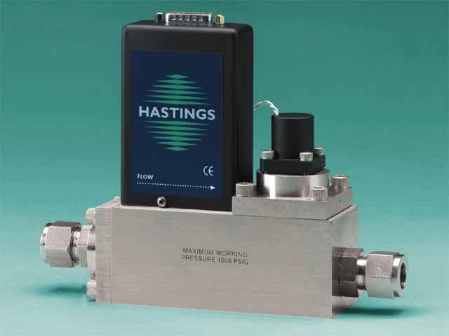
1 HASTINGS INSTRUCTION MANUAL 201/203 SERIES FLOWMETERS/CONTROLLERS page 1
2 Manual Print History The print history shown below lists the printing dates of all revisions and addenda created for this manual. The revision level letter increases alphabetically as the manual undergoes subsequent updates. Addenda, which are released between revisions, contain important change information that the user should incorporate immediately into the manual. Addenda are numbered sequentially. When a new revision is created, all addenda associated with the previous revision of the manual are incorporated into the new revision of the manual. Each new revision includes a revised copy of this print history page. Revision A (Document Number )...September 1999 page 2 Hastings Instruments reserves the right to change or modify the design of its equipment without any obligation to provide notification of change or intent to change.
3 Table of Contents 1.0 GENERAL INFORMATION Features Specifications Optional 4-20 ma Current Output Other Accessories INSTALLA ALLATION and OPERATION Receiving Inspection Power Requirements Output Signal Mechanical Connections Electrical Connections Operation Range Changing THEORY OF OPERATION Overall Functional Description Sensor Electronics Shunt Valve MAINTENANCE Authorized Maintenance Troubleshooting Adjustments End Cap Removal Printed Circuit Board Replacement Sensor Replacement Orifice Changes Replacement Parts WARRANTY and REPAIR AIR Warranty Policy Non-Warranty Repair Policy DRAWINGS and REFERENCES page 3
4 page 4
5 SECTION 1 General Information The Hastings HFM-201/HFC-203 series Mass Flowmeter (HFM-201) and controller (HFC-203) are designed to accurately measure and control mass flow over the range of 30 slm to 500 slm, without corrections or compensations for gas pressure and temperature with an accuracy of better than ±1% from the mean (±2% FS for 500 slm). Hastings mass flow instruments do not require any periodic maintenance under normal operating conditions with clean gases. No damage will occur from the use of moderate overpressures (~500 psi/3.45mpa) or overflows. Instruments are normally calibrated with the appropriate standard calibration gas (nitrogen) then a correction factor is used to adjust the output for the intended gas. Special calibrations for other gases, such as oxygen, helium and argon, are available upon special order. 1.1 Features LINEAR BY DESIGN. The HFM-201/HFC-203 series is inherently linear (no linearization circuitry is employed). Should recalibration in the field be desired (a calibration standard is required), the customer needs to simply set the zero and span points. There will be no appreciable linearity change of the instrument when the flowing gas is changed. NO FOLDOVER. The output signal is linear for very large over flows and is monotonically increasing thereafter. The output signal will not come back on scale when flows an order of magnitude over the full scale flow rate are measured. This means no false acceptable readings during leak testing. MODULAR SENSOR. The HFM-201/HFC-203 series incorporates a removable/replaceable sensor module. Field repairs to units can be achieved with a minimum of production line downtime. METER SETTLING TIME. Changes in flow rate for the HFM-201 are detected in less than 2 seconds when using the speed up circuitry. LOW TEMPERATURE TURE DRIFT. The temperature coefficient of span for the HFM-201/HFC-203 series is typically less than 0.05% of full scale/ C from C. The temperature coefficient of zero is typically less than 0.1 % of reading/ C from 0-50 C. FIELD RANGEABLE. The HFM-201/HFC-203 series is available in ranges from 30 slm to 500 slm. For HFC-203 controller s, an orifice change is required as well. Calibration, is required after all changes. CURRENT LOOP. The 4-20 ma option gives the user the advantages of a current loop output to minimize environmental noise pickup. page 5
6 1.2 Specifications Accuracy... ±1% full scale (F.S.) Repeatability... <±0.1% of F.S. Maximum operational pressure psi [3.45 MPa]. (option -P- up to 1000 psi [6.9 MPa]) Pressure coefficient... <0.01% of reading/psi [0.0015%/kPa] (N 2 ) Operating temperature C in non-condensing environment Temperature coefficient (zero)... ±0.1%/ C (±0.05%/ 0 C typical) Temperature coefficient (span)... ±0.1 ppm/ C (±0.05%/ 0 C typical) Zero drift... ±0.1%FS Leak integrity... <1x10⁻⁹ std. cc/s. Flow ranges... 30, 50, 100, 300, 500, 600 slm (N 2 ) Output VDC Optional output ma Power requirements... ±(15) 50 ma Wetted materials & 316 stainless steel, nickel 200, Viton, Au13Ni braze Attitude sensitivity of zero... < ±6.5% F.S. for 90 without re-zeroing {N 2 at 19.7 psia (135 KPa)} Controller weight lb (2.54 kg) Meter weight lb (1.50 kg) Electrical connector pin subminiature D Standard fittings... 1/2 Swagelok, 3/4 Swagelok, VCR, VCO page 6
7 1.3 Optional 4-20 ma Current Output An option to the standard 0-5 VDC output is the 4-20 ma current output that is proportional to flow. The 4-20 ma signal is produced from the 0-5 VDC output of the flowmeter. The current loop output is useful for remote applications where pickup noise could substantially affect the stability of the voltage output. The current loop signal replaces the voltage output on pin 6 of the D connector. The current loop may be returned to either the power supply ground or the -15 VDC connection on the power supply. If the current loop is returned to the power supply ground, the load must be between 0 and 600 ohm. If it is returned to the -15VDC, the load must be between 600 and 1200 ohm. Failure to meet these conditions will cause failure of the loop transmitter. The 4-20 ma I/O option can accept a current input. The 0-5 VDC command signal on pin 14 can be replaced by a 4-20mA command signal. The loop presets an impedance of 75 ohms and is returned to the power supply through the valve common. 1.4 Other Accessories Totalizer (TR-1J) The Hastings Flow Totalizer integrates the 0-5 VDC signal generated by the flowmeter to give a total flow reading. Count rates from 0 to 999 counts per minute are selectable by internal setting Hastings Model 40/200/400 Power Supply Hastings power supplies are available in either two or four channel versions. They convert 115 or 230VAC to the ±15 VDC required to operate the flowmeter. Interface terminals for the ±15 VDC input and the 0-5 VDC linear output signal are located on the rear of the panel. Also, a cable can be supplied with the power supply that provides the +15 VDC on pin 11 of a 15-pin D connector and the 0-5VDC output measurement on pin 6. Pins 5, 7 and 12 are common, and pin 7 is chassis ground. Throughout this manual, when reference is made to a power supply, it is assumed the customer is using a Hastings Model 200/400/40 supply. page 7
8 page 8
9 SECTION 2 Installation and Operation This section contains the necessary steps to assist in getting a new flowmeter/controller into operation as quickly and easily as possible. Please read the following thoroughly before attempting to install the instrument. 2.1 Receiving Inspection Carefully unpack the Hastings 201/203 series instrument and any accessories that have also been ordered. Inspect for any obvious signs of damage to the shipment. Immediately advise the carrier who delivered the shipment if any damage is suspected. Check each component shipped with the packing list. Insure that all parts are present (i.e., flowmeter, power supply, cables, etc.). Optional equipment or accessories will be listed separately on the packing list. There may also be one or more OPT-options on the packing list. These normally refer to special ranges or special gas calibrations. They may also refer to special helium leak tests, or high pressure tests. In most cases, these are not separate parts, but special options or modifications built into the flowmeter. 2.2 Power Requirements The HFM-201/HFC-203 series requires ±15 ±50 ma (HFM-201) +50 ma, -200 ma (HFC-203)for proper operation. The supply voltage should be sufficiently regulated to no more than 50 mv ripple. The supply voltage can vary from 14.0 to 16.0 VDC. Surge suppressors are recommended to prevent power spikes reaching the instrument. The Hastings power supply described in Section satisfies these power requirements. The HFM-201/HFC-203 series instruments have an integral 5 VDC ref. source. This stable voltage is on pin 15 of the D connector and may be used for the command voltage on the controller (HFC-203). 2.3 Output Signal The standard output of the flowmeter is a 0-5 VDC signal proportional to the flow rate. In the Hastings power supply the output is routed to the display, and is also available at the terminals on the rear panel. If a Hastings supply is not used, the output is available on pin 6 of the D connector and is referenced to pin 5. It is recommended that the load resistance be no less that 2kW. If the optional 4-20 ma output is used, the load impedance must be selected in accordance with Section Mechanical Connections The flowmeter may be mounted in any position as long as the direction of gas flow through the instrument follows the arrow marked on the bottom of the flowmeter case label. The preferred orientation is with the inlet and outlet fittings in a horizontal plane (if operating with a dense gas or at high pressures the instrument must be installed horizontally). When mounted in a different orientation the instrument should be re-zeroed at zero flow with the system pressurized to the expected operating pressure. The smallest of the internal passageways in the 201/203 series is the diameter of the sensor tube, which is (0.31 mm), so the instrument requires adequate filtering of the gas supply to prevent blockage or clogging of the tube. page 9
10 The pressure regulator and the plumbing upstream must be of sufficient size to minimize changes in the upstream pressure. When switching from full flow to zero flow, the inlet pressure of instrument should rise to no more that 30% above the inlet pressure at full flow. In general, high capacity regulators and large internal diameter plumbing help to make the system more stable. The pressure drop between the regulator and the instrument due to line resistance should be minimized. The differential pressure across the unit should be less than 6 of H 2 O at maximum flow. There are two 8-32 threaded holes, 0.25 deep, located on the bottom of the base that can be used to secure it to a mounting bracket, if desired (screws provided). Other holes for special mounting can be added to the end cap as desired. The standard inlet and outlet fittings for the 201/203 are 0.5 and 0.75 Swagelok (optional VCR or VCO fittings). The O-rings for the end cap and the sensor are Viton (optional Kalrez or Neoprene). It is suggested that all connections be checked for leaks after installation. This can be done by pressurizing the instrument (do not exceed 500 psig unless the flowmeter is specifically rated for higher pressures) and applying a diluted soap solution to the flow connections rated for higher pressures) and applying a diluted soap solution to the flow connections. 2.5 Electrical Connections If a power supply from Hastings Instruments is used, installation consists of connecting the HFM- 201/HFC-203 series cable from the D connector on the rear of the power supply to the D connector on the top of the flowmeter. If a different power supply is used, follow the instructions below when connecting the flow meter. This HFM-201/HFC-203 series requires Hastings cable #AF-8AM. Use of any other cable can severely damage the instrument and void the warranty. Figure 2.1 shows the schematic layout for connecting the instrument to an appropriate power supply. The power supply used must be capable of supplying +15VDC at 50mA and -15VDC at -200mA for each controller. These voltages must be referenced to a common ground. Connect -15VDC to pin 9 and +15VDC to pin 11. Pins 5 and 12 are both commons and they must be connected together and to the ground connection at the power supply. Do not connect them together at the flow controller as the resulting crosstalk could result in flow instabilities. Pin 7 is the case ground. It should be connected to the cable shield if available and to the AC ground to the power supply. Pin 6 is the output signal from the flow controller. This output will be 0-5VDC, 5VDC being 100% of rated or full flow. Pin 14 is the command input. This should be a 0-5VDC signal and must be free of spikes or other electrical noise, as these will generate false flow commands that the controller would attempt to flow. Pin 15 is a well regulated +5.00VDC output reference. The reference is designed to provide the command signal for pin 14 by connecting one end of a potentiometer to pin 15 and the other end to ground. The center lead would then be connected to pin 14. If a valve override switch is not desired, the unit is ready for use at this time. If the override switch is desired, connect the center pin of a single pole, three-position switch with the center off position to pin 8. Connect +15VDC to one end of the switch, and -15VDC to the other end. This will result in the valve being full open when +15VDC is supplied to pin 8, off when -15VDC is supplied and auto-control when there is no connection to pin 8 (OPEN-AUTO-CLOSE). This setup will be adequate for most purposes, but there will be a small delay for capacitors to charge between switch operation and control override. page 10
11 PIN 14 PIN 9 PIN 14 PIN 11 PIN 6 PIN 1 PIN 8 SHIELD PIN 5 VALVE CONTROL MODE OUTPUT REFERENCE Figure Operation The standard instrument output is a 0-5 VDC out and the signal is proportional to the flow i.e., 0 volts = zero flow and 5 volts = 100% of rated flow. The 4-20 ma option is also proportional to flow, 4 ma = zero flow and 20 ma = 100% of rated flow. It is suggested that all connections be checked for leaks after installation. This can be done by pressurizing the instrument (do not exceed 500 psig unless the instrument is specifically rated for higher pressures) and applying a diluted soap solution to the connections Operating Conditions For proper operation, the combination of ambient temperature and gas temperature must be such that the flowmeter temperature remains between 0 and 50 C. (Most accurate measurement of flow will be obtained if the flowmeter is zeroed at operating temperature as temperature shifts result in some zero offset.) The 201/203 series is intended for use in non-condensing environments only. Condensate or any other liquids which enter the flowmeter may destroy its electronic components Zero Check Turn the power supply on if not already energized. Allow for a 1 hour warm-up. Stop all flow through the instrument and wait 2 minutes. Caution: Do not assume that all metering valves completely shut off the flow. Even a slight leakage will cause an indication on the meter and an apparent zero shift. For the standard 0-5 VDC output, adjust the zero potentiometer located on the lower outlet side of the flowmeter until the meter indicates zero. For the optional 4-20 ma output, adjust the zero potentiometer so that the meter indicates slightly more than 4 ma, i.e to 4.05 ma. This slight positive adjustment ensures that the 4-20 ma current loop transmitter is not in the cut-off region. The error induced by this adjustment is approximately 0.3% of full scale. This zero should be checked periodically during normal operation. Zero adjustment is required if there is a change in ambient temperature, or vertical orientation of the flowmeter/controller. page 11
12 2.6.3 High Pressure Operation Maintainance and Repair 4-3 When operating at high pressure, the increased density of gas will cause natural convection to flow through the sensor tube if the instrument is not mounted in a level position. This natural convection flow will be proportional to the system pressure. This will be seen as a shift in the zero flow output that is directly proportional to the system pressure Blending of Gases In the blending of two gases, it is possible to maintain a fixed ratio of one gas to another. In this case, the output of one flow controller is used as the reference voltage for the set point potentiometer of a second flow controller. The set point potentiometer then provides a control signal that is proportional to the output signal of the first flow controller, and hence controls the flow rate of the second gas as a percentage of the flow rate of the first gas. EXAMPLE: Flow controller A has slpm range with a 5.00 volt output at full scale. Flow controller B has 0-10 slpm range with a 5.00 volt output at full scale. If flow controller A is set at 80 slpm, its output voltage would be 4.00 volts (80 slpm/100 slpm x 5.00 volts = 4.00 volts). If the output signal from flow controller A is connected to the command potentiometer of flow controller B, it then becomes a variable reference voltage for flow controller B proportional to the flow rate of flow controller A. If the set point potentiometer of flow controller B is set at 50% of full scale, and the reference voltage from flow controller A is 4.00, then the command signal going to flow controller B would be 2.00 volts (4.00 volts x 50.0% = 2.00 volts). The flow of gas through flow controller B is then controlled at 4 slpm (2.00 volts/5.00 volts x 10 slpm = 4 slpm). The ratio of the two gases is 20:1 (80 slpm/4slpm). The % mixture of gas A is 95.2 (80slpm/ 84slpm and the % mixture of gas B is 4.8% (4 slpm/84 slpm). Should the flow of flow controller A drop to 78 slpm, flow controller B would drop to 3.9 slpm, hence maintaining the same ratio of the mixture. (78 slpm/100slpm x 5v = 3.90v x 50% = 1.95v; 1.95v/5.00v x 10 slpm = 3.9 slpm; 78 slpm:3.9 slpm = 20:1) 2.7 Operation Operation with a Hastings power supply. There are two controls for each flow controller connected to a Hastings power supply. A switch labeled OPEN; AUTO; CLOSED (valve over ride) and a potentiometer knob labeled COM- MAND. For normal operation, the valve over ride switch will be in the AUTO position. The CLOSE position removes all power from the valve, shutting off flow regardless of the command pot setting. The OPEN position applies full available valve voltage to the valve, causing it to open, regardless of the command pot setting. The OPEN position is useful for purging systems. It is recommended that the valve over ride switch not be left in this position for extended periods of time, with no flow through the controller, as a small positive zero shift may be observed. The COMMAND pot adjusts the 0-5 VDC command signal sent to the flow controller. The setting for each controller connected to the power supply can be observed by rotating the POWER/CHANNEL SELECT knob to the channel connected to the controller that you wish to observe, and rotating the FLOW/COMMAND knob to COMMAND. The display will then indicate the command signal. (Depending on how the power supply was set up, the display could indicate in flow units or percent of full scale.) To observe the flow output of the flow controller, rotate the FLOW/COMMAND knob to FLOW. The display will now indicate the flow output signal. page 12
13 2.7.2 Operation with a power supply other than a Hastings. The flow controller must be connected to the power source as specified in section 2.6. In general, a 0-5 VDC command signal proportional to the intended flow (0 volts = zero flow; 5 volts = 100% of rated flow) must be applied to pin 14 of the D connector. A 0-5 VDC signal proportional to the flow rate through the instrument will be present on pin 6 of the D connector. The control mode is selected via pin 8 of the D connector. Apply +15 volts for full open, -15 volts for closed and allow pin 8 to float for flow proportional to the command voltage. Refer to your power supply manual for the specifics of implementing these parameters Operation with an external sensor. (Fig. 2.2) In some instances, it might be desirable to use an external sensor to provide process information to the control circuitry in the flow controller. For example, you might want to control the pressure in a vacuum system by adjusting the rate at which the system is backfilled with a gas. The new, enhanced HFC series of flowcontrollers have provision for accepting a 0-5VDC output from an external sensor at pin 13 of the D connector. To activate this feature, the cover of the HFC must be removed to gain access to PC-828 and move a jumper on JP1. JP1 is a three pin jumper block located just below the D connector. In the normal operating mode, the jumper covers the bottom two pins. To select External Sensor, move the jumper to the upper two pins. This swaps the flow input to the controller circuit from the flowmeter output to pin 13 of the D connector Response to Command Changes The response of the control circuit to changes to the command signal is set at the factory for fast, stable response. Should it be necessary, the response is adjustable using the set of jumpers labeled JP2. JP2 is located at the upper left corner of PC-828. The pins are numbered 1-6, from top to bottom. The fastest response to command changes is obtained when all six pins of JP2 are covered by the jumpers. This setup allows large overshoot and undershoot swings in the actual flow rate while the control circuit is establishing control at the new command point. The slowest response to command changes is obtained when none of the pins of JP2 are covered by jumpers. This setup results in no overshoot or undershoot in the actual flow rate as the controller circuit establishes control at the new command point. To adjust the response, you need a means of producing a step change in the command voltage from 10% of full scale to 100% of full scale. Follow the steps outlined below: 1) Cover all six pins of JP2 with jumpers. (see fig. 2.2) 2) Set the command voltage to 10% of full scale. Allow the flow to stabilize. 3) Step change the command voltage to 100%, and observe the flow through the controller. If the overshoot is too large, remove the jumper over pins 1 and 2. Reset the command voltage to 10%, and allow the controller to stabilize. 4) Step change the command voltage to 100%, and observe the flow through the controller. If the overshoot is still too large: a) Remove the jumpers over pins 3 and 4. Reset the command voltage to 10%, and allow the controller to stabilize. b) Repeat the step change from 10% to 100%. If the overshoot is still too large, remove the last jumper (pins 5 and 6). This is the soft start configuration. If the response is too slow: a) Replace the jumper over pins 1 and 2, and remove the jumper over pins 3 and 4. Reset the command voltage to 10%, and allow the controller to stabilize. b) Repeat the step change from 10% to 100%. If the response is still too slow, replace the jumper over pins 3 and 4. This is the fast response configuration. 5) To prevent loss of the unused jumpers, place each one over one pin only on JP2. page 13
14 2.7.5 Operating Tempera emperature For proper operation, the combination of ambient temperature and gas temperature must be such that the flowcontroller temperature remains between 0 and 50 0 C. Most accurate measurement of flow will be obtained if the flow controller is re-zeroed at operating temperature, as temperature shifts result in some zero offset. 2.8 Range Changing: The range of the flow controller can be changed in the field if recalibration facilities are available. The flow controller may require a different orifice, which can be purchased separately from the factory. A listing of the orifices available and their flow rates can be found in Section 5.0. The instructions to change the flow range can be found in Section 4.6. JP1 TP8 P3 TP2 C10 TP7 TP5 JP2 TP11 R5 JP1 C2 C13 P1 C8 R2 D5 D3 C11 C3 TP6 TP9 R3 D1 P2 D2 C9 C7 R11 C19 R1 R6 U4 R12 TP13 TP14 TP10 R20 R23 U1 C6 C1 TP1 C4 JP2 Figure 2.2 page 14
15 SECTION 3 Theory of Operation This section contains an overall functional description of HFC Flow Controllers. Detailed schematics and parts lists can be found at the end of the manual in Section 6.0. In this section and other sections throughout this manual, when a power supply is mentioned, it is assumed that the customer has a Hastings Power Supply. These sections are not applicable if another type of power supply is used. 3.1 Overall Functional Description: The HFC Flow Controller consists of a sensor, electronic circuitry, a shunt and a valve. The sensor measures the flow rate from 0 to 10 sccm of the gas to be metered. The shunt divides the flow such that the flow through the sensor is a precise percentage of the flow through the shunt. The flow through the sensor and the shunt is always laminar. The circuit board amplifies the sensor output and uses this output to control the valve position. The 2 stage valve employs an automatic metering solenoid, used to control the pressure differential across the main diaphragm seat assembly. All of these components working together result in a fast, stable flow controller. heater TC-1 TC Sensor: Figure 3.1 The Hastings HFM-201/HFC-203 series instruments operate on a unique thermal electric principle whereby a metallic capillary tube is heated uniformly by a resistance winding attached to the midpoint of the capillary (see Figure 3.1). Thermocouples TC-1 and TC-2 are welded at equal distances from the midpoint and develop equal outputs at zero flow. When flow occurs through the tubing, heat is transferred from the tube to the gas on the inlet side, and from the gas back to the tube on the outlet side creating an asymmetrical temperature distribution (see Figure 3.2). The thermocouples sense this decrease and increase in the capillary tube temperature and produce a millivolt output signal proportional to that change. For a constant power input, the differential thermocouple output is a function of the mass flow rate and the heat capacity of the gas. Since the heat capacity of many gases is relatively constant over wide ranges of temperature and pressure, the flowmeter may be calibrated directly in mass units for those gases. Changes in gas composition usually only require application of a simple multiplier to the air calibration to account for the difference in heat capacity and thus the flowmeter is capable of measuring a wide variety of gases. The HFM sensor measures approximately 10 sccm., full scale flow. 3.3 Electronics: The HFM-201/HFC-203 series instruments use a thermal flow sensor to measure through a capillary tube, which is a fixed percentage of the total flow through the instrument. This sensor develops an output signal proportional to flow which is approximately 1 mv full scale magnitude. This signal is amplified by the meter circuitry until is VDC. This 5 volt output is sent back to the power supply and to the flowmeter circuitry, if applicable. At the power supply the 5 volt output is sent to the terminals on the back and to the decoding circuitry in the display which converts it to a 3-digit output. page 15
16 The controller circuitry utilizes the Command and the Flow voltages as input signals. The 0-5VDC command signal is subtracted from the 0-5VDC flow signal creating an error signal. This signal is amplified and causes the solenoid valve to move. The amount and direction of the movement is dependent upon the value and the sign of the error signal, and tends to minimize the error signal. Figure Shunt: Measurement of flow rates higher than the 10 sccm full scale is achieved by dividing the flow with a fixed ratio shunting arrangement, as is illustrated in Figure 3.3. This is accomplished by placing the measuring capillary tube parallel with one or more dimensionally similar channels, called a laminar flow element (LFE). Therefore, the sensor only needs to heat the gas passing through the capillary tube resulting in low power requirements, while retaining all the mass measuring characteristics. The HFC-203 uses corrugated and fused shunts similar to the shunts used in the lower flow range instruments. These high range shunts are factory adjustable from 0-30 slpm to slpm (see Figure 3.4), using specific corrugated shunts that give the desired flow range. Figure 3.3 page 16
17 Figure Valve: At flowrates higher than 30 slm, two valves are used in parallel. A solenoid valve is used as a pilot valve to control a much larger pneumatic diaphragm valve. The pilot valve is an automatic metering solenoid valve. While most solenoids operate in either the fully open or fully closed state, the automatic metering solenoid valve is designed to control flow (see Figure 3.5). A spring, connected to the plunger assembly, holds a magnetic plunger tightly against an orifice to shut off flow. The magnetic plunger is surrounded by an electrical coil, which when energized with electrical current lifts the plunger off the orifice and allows flow to pass between the orifice and the plunger seat. Controlling the current through the coil controls the distance between the orifice and the plunger seat, thus effectively controlling the flow through the valve. Figure 3.6 shows the combination of the two valves. When pressure is first applied to the upstream side of the valve, flow will pass through until the chamber above the diaphragm is pressurized through a small bleed screw. System pressure and spring force will then close the valve. The pilot valve controls the pressure in the chamber above the diaphragm thus controlling the height of the large plunger above its seat. Figure 3.5 Figure 3.6 page 17
18 page 18
19 SECTION 4 Maintenance This section contains service and calibration information. Some portions of the instrument are delicate. Use extreme care when servicing the flow controller. The potentiometer positions and the electrical components referred to in the troubleshooting section can be found in Section 6.0 on the electrical component layout drawing. 4.1 Authorized Maintenance With proper care in installation and use, the flow controller will require little or no maintenance. If maintenance does become necessary, most of the instrument can be cleaned or repaired in the field. Some procedures may require recalibration. Do not attempt these procedures unless facilities are available. Entry into the sensor or tampering with the printed circuit board will void warranty. Do not perform repairs on these assemblies while unit is still under warranty. 4.2 Troubleshooting SYMPTOM OM: Output reads 40% of flow with no flow. Zero pot has no effect. CAUSE USE: Power supply locked up or shorted out. ACTION CTION: Turn off power supply for a few seconds, then turn back on. If this proves ineffective, disconnect the unit from the power supply. If power supply display does not return to zero, then a regulator chip in the power supply is probably burned out. Check supply voltages and replace faulty regulator. If display returns to zero after disconnecting the power supply from the unit there is a short in the unit to ground. Check capacitors C10 & C11 first. SYMPTOM OM: Override switch is in CLOSE position, but flow remains or 0.00 VDC is commanded and flow remains. CAUSE: Orifice out of adjustment or faulty op-amp ACTION CTION: Check valve voltage at connector pins TP-3 & TP-6. If voltage is less than 3.00 VDC, then turn orifice clockwise until flow stops. If voltage is greater than 3.00 VDC. If they are greater, replace U1; if less, replace transistor Q1. SYMPTOM: Output of unit is proportional to flow but extremely small and not correctable by span pot. CAUSE: Sensor is not being heated. ACTION CTION: Unplug connector J2. Check the following resistance: The resistance between pins 2 & 3 of the sensor should be approximately 2500 ohms (see Figure 3.1 on page 8). The resistance between pins 1 & 4 should be approximately 2.3 ohms. The resistance between pins 2 & 3 and the base of the sensor should be essentially infinite. If not, replace the sensor unit. If sensor reads O.K., check the voltage output on pins 2 & 3 of the jack in the board. If it does not read approximately 22 VDC then replace op-amp U2. SYMPTOM OM: Sensor has proper resistance readings, but little or no output with flow. CAUSE: Plugged sensor. ACTION CTION: Shut off gas supply and power supply. Remove cover and PC board from unit. Remove sensor assembly and examine. If sensor has evidence of plugging, clean or replace as applicable page 19
20 SYMPTOM: Flow controller oscillates. CAUSE: Flow controller not adjusted for the dynamics of the flow system. ACTION CTION: Check upstream and downstream pressures. The gas supply regulator should not have excessive lockup when flow shuts off. Also ensure that there is not a large drop in pressure between the regulator and the instrument due to line resistance. Oscillations can also be caused if a large flow restriction is pneumatically close to the downstream end of the flow controller. The differential pressure across the unit must be between psig. SYMPTOM OM: Little or no flow, even with Valve Override switch OPEN. CAUSE: Plugged orifice. ACTION CTION: Verify the presence of a psig pressure across the instrument. If present, shut off gas supply and power supply. Remove orifice per Section 4.9. Examine orifice. If plugged, clean or replace as applicable. Reassemble valve. SYMPTOM OM: Flowmeter reads other than 0.00 VDC with no flow, or there is a small flow when flowmeter reads 0.00 VDC. CAUSE USE: ZERO potentiometer is out of adjustment. ACTION CTION: Shut off all flow. Adjust ZERO potentiometer until output reads 0.00 VDC. SYMPTOM: Flowmeter out of calibration and nonlinear. CAUSE: Leaks in gas inlet or outlet fittings. ACTION CTION: Check all fittings for leaks by placing soap solution on all fittings between gas supply and final destination of gas. Check flowmeter for leaks. Replace O rings if required or recalibrate as necessary. 4.3 ADJUSTMENTS page Calibration Procedure: (Figure 4.1) NOTE: Adjusting the SPAN pot will require the use of a calibration reference in Step Connect power cable to D connector as specified in Section 2.7. Allow instrument to warm up for 30 minutes with 10% flow and instrument in AUTO position. 2. Set ZERO (R19) potentiometer for VDC output. 3. Turn on gas supply to inlet of instrument. Put Figure 4.1 Valve Override switch into CLOSE position. Adjust the orifice underneath controller to obtain zero flow. Put Valve Override switch into AUTO. Ensure that full range flow can still be obtained at minimum inlet pressure. Span Zero 4. Set command to 100%. Adjust SPAN (R29) pot until the flow reference reads full scale flow (5.000 VDC). NOTE: Perform this step only if a calibrated reference flowmeter is available. 5. Record flowmeter and flow reference outputs for flow rates of 20%, 40%, 60%, 80% and 100%.
21 4.3.2 Miscellaneous adjustments Periodically, during normal operation, the ZERO should be checked and adjusted when required. If system parameters change, the RESPONSE pot may require a small adjustment for optimum stability. If the instrument is not shutting completely off when Valve Override switch is in the CLOSE position, the orifice may require approximately 1/8 turn clockwise. 4.4 End Cap Removal: The end cap on the inlet side must be removed to gain access to the filter or shunt assembly. First shut off the supply of gas to the instrument. Disconnect the Swagelok fitting on the inlet and outlet sides of the transducer, and remove it from the system plumbing. Remove the four hex bolts holding the end cap to the instrument (see Figure 4.1). Carefully remove the end cap, filter, wave spring (if present) and shunt, noting their order and proper orientation. The shunt can be severely damaged if dropped. Examine the filter and shunt. If either is dirty or blocked, clean or replace as applicable. Reassembly is the reverse of the removal procedure. Recalibration of the HFC is necessary. 4.5 Printed Circuit Board Replacement In the unlikely event that the PC board fails, it is easily removed from the instrument and replaced with a spare to minimize instrument downtime. Replacement of the PC board will require the instrument to be recalibrated per Section Unplug the power cable from the top of the transducer. Remove the two jackscrews next to the D connector and the two screws on the sides of the cover. Lift off the cover and unplug the four-wire sensor plug and the two wire valve plug, noting their orientation prior to removal. Remove the screw that holds the PC board to the sensor. Troubleshoot or replace as applicable. Installation is the reverse of the above procedure. Recalibrate if any components were changed or if any potentiometers were adjusted. 4.6 Sensor Replacement: If the sensor fails or becomes plugged it can be removed. Remove the cover and the PC board per Section 4.7 above. Remove the three bolts holding the sensor to the instrument base. Remove the sensor from the base noting the two O-rings (Parker 2-005, V884-75) between the sensor and the base. If the sensor is plugged it can be cleaned by running a fine wire (approximately 0.008" diameter) through the tube. If sensor needs replacement, obtain another from the factory and install it. Ensure that O-rings are clean and intact. Install O-rings on seating surface, then carefully place sensor over O-rings and tighten down the three screws evenly. Replacement of sensor will require recalibration per Section Orifice Changes: The orifice may require replacement if a flow range change is desired, if a large change in differential pressures across the valve is desired or in the event that a small orifice becomes plugged. Replacement orifices can be acquired from the factory. See Section 4.8 for the list of standard orifices and their flow rates in air. When using nonstandard pressures or gases that have specific gravities different than air (such as hydrogen or helium), the diameter of the orifice must be calculated using the following procedure: page 21
22 A) Determine the minimum expected upstream pressure (Pu) in PSI absolute and the maximum expected downstream pressure (Pd) in PSI absolute for full flow conditions. B) If Pu >2Pd, use formula 1; otherwise use formula 2. Where: formula 1: formula 2: D= s Q Pu D = Diameter in inches Q = Flowrate in standard liters per minute P = Pu - Pd in PSI Pu = Upstream pressure in PSIA Pd = Downstream pressure in PSIA D= Q P Pd s s = Specific gravity of gas Choose the orifice form Section 5.0 that has the closes larger diameter to the calculated diameter HFC-203 Orifice To change the orifice in the HFC-203 unit, the valve must be dismantled. Remove the four 1/4" Allen head machine screws in the top of the main valve. Lift off the valve top, exposing the spring and diaphragm. Note that a small brazed ball bearing is on the down stream side of the valve top. Remove the spring and diaphragm assembly. The orifice is located in the bottom of the valve body and can be removed with a 9/16 socket wrench. See Figure 4.5. To reinstall an orifice, first install the gasket onto the orifice (replacement gaskets can be obtained from the factory). Next screw the orifice into the valve base. Snug up the orifice but do not overtighten. Place diaphragm assembly into the base. Line up the two small holes in the diaphragm with the two small holes in the valve base. Place the spring on top of the diaphragm. Examine the o-ring on the valve top for damage if required. Install the valve top, ensuring that the ball bearing in the side is on the downstream side. Tighten down the valve top evenly to insure a proper seal at the diaphragm. page 22 Figure 4.2
23 4.8 REPLACEMENT PARTS The following is a list of the available replacement parts and their factory stock numbers. The HFM-201 and the HFC-203 shunts and filter discs are interchangeable. The same sensor module is used on all models. All HFM models use the same printed circuit board. STOCK NO. DESCRIPTION AIR RANGE Orifice HFC Orifice HFC Orifice 0.13 HFC Orifice HFC Orifice HFC Orifice HFC Orifice HFC LARGE FILTER DISC HFC SENSOR MODULE (10 SCCM ONLY) ALL MODELS SENSOR MODULE ALL MODELS NOTE: Ranges listed are for same standard temperature and pressure. To place an order or to obtain information concerning replacement parts, contact the factory or our local manufacturer s representative in you area. See below, or this manual s last page for the address or phone number. When ordering, include the following information: Instrument model number Part description Hastings part number page 23
24 page 24
25 SECTION 5 Warranty and Repair 5.1 Warranty Policy Hastings Instruments warrants this product, for a period of one year from the date of shipment, to be free from defects in material and workmanship. This warranty does not apply to defects or failures resulting from unauthorized modification, misuse or mishandling of the product. This warranty does not apply to batteries or other expendable parts, nor to damage caused by leaking batteries or any similar occurrence. This warranty does not apply to any instrument which has had a tamper seal removed or broken. This warranty is in lieu of all other warranties, expressed or implied, including any implied warranty as to fitness for a particular use. Hastings Instruments shall not be liable for any indirect or consequential damages. Hastings Instruments will, at its option, repair, replace, or refund the selling price of the product if Hastings Instruments determines in good faith, that it is defective in materials or workmanship during the warranty period. Defective instruments should be returned to Hastings Instruments together with a written statement of the problem and a Return Material Authorization (RMA) number. Please consult the factory for your RMA number before returning any product for repair. 5.2 Non-Warranty Repair Policy Any product returned for a non-warranty repair must be accompanied by a purchase order, RMA form and a written description of the problem with the instrument. If the repair cost is higher, you will be contacted for authorization before we proceed with any repairs. If you then choose not to have the product repaired, a minimum will be charged to cover the processing and inspection. Please consult the factory for your RMA number before returning any product for repair. TET-HASTINGS INSTRUMENTS 804 NEWCOMBE AVENUE HAMPTON, VIRGINIA U.S.A. ATTENTION: REPAIR DEPARTMENT TELEPHONE (757) FAX (757) page 25
26 page 26
27 SECTION 6 Drawings Standard PCB page 27
28 page 28 Standard PCB parts list
29 Enhanced PCB page 29
30 page 30 Enhanced PCB parts list
31 Enhanced PCB schematic page 31
32 page 32 Enhanced PCB W/RF rejection
33 Enhanced PCB W/RF rejection parts list page 33
34 page 34 Enhanced PCB W/RF rejection schematic
35 Enhanced PCB W/RF rejection schematic page 35
36 page 36
TELEDYNE HASTINGS INSTRUMENTS
 TELEDYNE HASTINGS INSTRUMENTS INSTRUCTION MANUAL 200/202 SERIES FLOWMETERS/CONTROLLERS Manual Print History The print history shown below lists the printing dates of all revisions and addenda created for
TELEDYNE HASTINGS INSTRUMENTS
 TELEDYNE HASTINGS INSTRUMENTS INSTRUCTION MANUAL 200/202 SERIES FLOWMETERS/CONTROLLERS ISO 9001 C E R T I F I E D Manual Print History The print history shown below lists the printing dates of all revisions
TELEDYNE HASTINGS INSTRUMENTS
 TELEDYNE HASTINGS INSTRUMENTS MODELS HFM-D-3 & 305 HFC-D-3 & 307 FEATURES Flows from 0-25 slm (N2 Equivalent) up to 0-2500 slm (N2 Equivalent) Accuracy in Nitrogen (0.2% of Full scale + 0.5% of Reading)
TELEDYNE HASTINGS INSTRUMENTS
 TELEDYNE HASTINGS INSTRUMENTS INSTRUCTION MANUAL DIGITAL VT ISO 9001 C E R T I F I E D Manual Print History The print history shown below lists the printing dates of all revisions and addenda created for
Thermal Mass Flow Meter (Analog)
") Meter (Analog) Precision Fluidics 2 Meters Traditional Analog Flow Meter Parker Meters provide reliable analog flow measurements configured for your process conditions. Each meter offers a linear flow
Meter (Analog) Precision Fluidics 2 Meters Traditional Analog Flow Meter Parker Meters provide reliable analog flow measurements configured for your process conditions. Each meter offers a linear flow
TELEDYNE HASTINGS INSTRUMENTS
 TELEDYNE HASTINGS INSTRUMENTS INSTRUCTION MANUAL HPM 4/5/6 VACUUM GAUGE ISO 9001 C E R T I F I E D Manual Print History The print history shown below lists the printing dates of all revisions and addenda
5001TCP SPEED CONTROLLER
 INSTALLATION AND SETTING UP MANUAL 5001TCP SPEED CONTROLLER WARNING Disconnect all incoming power before working on this equipment. Follow power lockout procedures. Use extreme caution around electrical
5001TCP SPEED CONTROLLER
 VARIABLE SPEED DRIVE CONTROLLER INSTALLATION AND SETTING UP MANUAL 5001TCP SPEED CONTROLLER With PC101 Torque Limit Control WARNING Disconnect all incoming power before working on this equipment. Follow
MM1/MM2 INSTALLATION & MAINTENANCE INSTRUCTIONS
 MM1/MM2 INSTALLATION & MAINTENANCE INSTRUCTIONS DESCRIPTION / IDENTIFICATION The MM series proportional control valves utilize ProportionAir's unique closed loop control technology for superior control
MPV1 INSTALLATION & MAINTENANCE INSTRUCTIONS
 MPV1 INSTALLATION & MAINTENANCE INSTRUCTIONS DESCRIPTION / IDENTIFICATION The MPV1 series valve uses Proportion- Air closed loop technology for pressure control. It gives an output pressure proportional
MPV1 INSTALLATION & MAINTENANCE INSTRUCTIONS
 MPV1 INSTALLATION & MAINTENANCE INSTRUCTIONS DESCRIPTION / IDENTIFICATION The MPV1 series valve uses Proportion- Air closed loop technology for pressure control. It gives an output pressure proportional
Harris IRT Enterprises Digital Resistance Tester Model XP
 Harris IRT Enterprises Digital Resistance Tester Model 5012-06XP Specifications & Dimensions 2 Theory of Operation 3 Operator Controls & Connectors 4 Test Connections 5 Calibration Procedure 6-7 Options
12 Series Linear Actuators. Operation & Maintenance Manual, Analog Positioner Installation
 12 Series Linear Actuators Operation & Maintenance Manual, Analog Positioner Installation 6810 POWERLINE DR.-FLORENCE, KY. 41042 - TELEPHONE 859-727-7890, TOLL FREE 1-800-662-9424 FAX. 859-727-4070, E-MAIL:
QB4 PRESSURE CONTROL VALVE INSTALLATION & MAINTENANCE INSTRUCTIONS
 QB4 PRESSURE CONTROL VALVE INSTALLATION & MAINTENANCE INSTRUCTIONS DESCRIPTION The QB4 is a closed loop electronic pressure regulator consisting of two solenoid valves, an internal pressure transducer,
MAGPOWR Spyder-Plus-S1 Tension Control
 MAGPOWR TENSION CONTROL MAGPOWR Spyder-Plus-S1 Tension Control Instruction Manual Figure 1 EN MI 850A351 1 A COPYRIGHT All of the information herein is the exclusive proprietary property of Maxcess International,
P200 P/I Transducer. Installation, Operation, and Maintenance Instructions INTRODUCTION
 INTRODUCTION Scope This manual provides instructions for the installation, adjustment, maintenance, and parts ordering of the P200 Pneumatic-to-Current P/I Transducer. Due to its over-engineered design,
Troubleshooting Bosch Proportional Valves
 Troubleshooting Bosch Proportional Valves An Informative Webinar Developed by GPM Hydraulic Consulting, Inc. Instructed By Copyright, 2009 GPM Hydraulic Consulting, Inc. TABLE OF CONTENTS Bosch Valves
DMC mA Positioner
 DMC-100 4-20mA Positioner TELEPHONE: +1-859-727-7890 TOLL FREE: +1-800-662-9424 FAX: +1-859-727-4070 E-MAIL: DVOGES@INDELAC.COM MROBINSON@INDELAC.COM TCAYWOOD@INDELAC.COM SHIPPING ADDRESS: 6810 POWERLINE
VSO Thermally Compensated Proportional Valve
 4 VSO Thermally Compensated Proportional Valve Typical Applications Gas Chromatography Mass Spectrometry Ventilators O 2 Concentrators/Conservers Anaesthesia Delivery & Monitors Pressure & Control Mass
Data Sheet. I/P and E/P converters. RS stock numbers ,
 Data Pack G Issued March 997 3-4998 Data Sheet I/P and E/P converters RS stock numbers 79-47, 79-48 Standard (electro-mechanical) Construction Housing Zinc diecastings, passivated and black epoxy paint,
Miniature Proportional Valve Thermally Compensated Proportional Valve. Physical Properties
 VSO Miniature Proportional Valve Thermally Compensated Proportional Valve Typical Applications Gas Chromatography Mass Spectrometry Ventilators O 2 Concentrators/Conservers Anaesthesia Delivery & Monitors
Type 500X. Electropneumatic Transducer (I/P, E/P) Installation, Operation and Maintenance Instructions. Ordering Information.
 Installation, Operation and Maintenance Instructions. Ordering Information.") Type 500X Electropneumatic Transducer (I/P, E/P) Installation, Operation and Maintenance Instructions Ordering Information Type 500X I/P Transducers Output Range Part Number Input psi kpa Impedance 500-AA
Type 500X Electropneumatic Transducer (I/P, E/P) Installation, Operation and Maintenance Instructions Ordering Information Type 500X I/P Transducers Output Range Part Number Input psi kpa Impedance 500-AA
RESISTIVITY MONITOR/CONTROLLERS
 RESISTIVITY MONITOR/CONTROLLERS Installation Operation Maintenance User Manual for Models: 750, 752, 753, 762 2450 Impala Drive Carlsbad, CA 92010-7226 USA Tel: 1-760-438-2021 Fax: 1-800-869-7668 / 1-760-931-9189
INSTRUCTION MANUAL 272-5X5 ANALOG TRANSMITTER (210 SERIES FLOW METERS) 272-5X7 ANALOG TRANSMITTER (220/240 SERIES FLOW METERS)
 272-5X7 ANALOG TRANSMITTER (220/240 SERIES FLOW METERS)") INSTRUCTION MANUAL 272-5X5 ANALOG TRANSMITTER (210 SERIES FLOW METERS) 272-5X7 ANALOG TRANSMITTER (220/240 SERIES FLOW METERS) 272-5X8 BIDIRECTIONAL TRANSMITTER (210/240 SERIES FLOW METERS) TABLE OF CONTENTS
INSTRUCTION MANUAL 272-5X5 ANALOG TRANSMITTER (210 SERIES FLOW METERS) 272-5X7 ANALOG TRANSMITTER (220/240 SERIES FLOW METERS) 272-5X8 BIDIRECTIONAL TRANSMITTER (210/240 SERIES FLOW METERS) TABLE OF CONTENTS
NT HIGH-TEMPERATURE ELECTRONIC FLOWMETER, MODEL 4401
 P/N 1400 (Rev. A 08/12) NT HIGH-TEMPERATURE ELECTRONIC FLOWMETER, MODEL 4401 User Guide Table of Contents Introduction... 2 Dimensions... 3 Installation... 5 Provided Equipment... 5 Operating Environment...
HASTINGS INSTRUMENTS. AVG and AVC MODULE
 HASTINGS INSTRUMENTS AVG and AVC MODULE TELEDYNE BROWN ENGINEERING Hastings Instruments P.O. Box 1436 Hampton, Virginia 23661 U.S.A. MANUAL 137-0596 Rev.B ISO 9001 C E R T I F I E D page 1 page 2 Contents
Type 500X. Electropneumatic Transducer (I/P, E/P) Installation, Operation and Maintenance Instructions. Ordering Information.
 Installation, Operation and Maintenance Instructions. Ordering Information.") Type 500X Electropneumatic Transducer (I/P, E/P) Installation, Operation and Maintenance Instructions Ordering Information Type 500X I/P Transducers Output Range Part Number Input psi kpa Impedance 500-AA
Type 500X Electropneumatic Transducer (I/P, E/P) Installation, Operation and Maintenance Instructions Ordering Information Type 500X I/P Transducers Output Range Part Number Input psi kpa Impedance 500-AA
TELEDYNE HASTINGS INSTRUMENTS
 TELEDYNE HASTINGS INSTRUMENTS INSTRUCTION MANUAL HFM-D-301/305 FLOW METERS HFC-D-303/307 FLOW CONTROLLERS Manual Print History The print history shown below lists the printing dates of all revisions and
GP1/GP2 INSTALLATION & MAINTENANCE INSTRUCTIONS
 GP1/GP2 INSTALLATION & MAINTENANCE INSTRUCTIONS Description & identification General specifications Connection procedure Recalibration procedure Repair procedure Dimensions, ordering and accessories Before
Check Valve AP64 P.149. Vacuum Generator Vacuum Generator Module Vacuum Generator Module AP7 & 70 AP71 AP72. Flow Switch Flow Switch (For high flow)
") Check Valve eries Check Valve AP64 P.149 Vacuum Generator Vacuum Generator Vacuum Generator Module Vacuum Generator Module Flow witch Flow witch Flow witch (For high flow) eries AP7 & 7 AP71 AP72 eries
Check Valve eries Check Valve AP64 P.149 Vacuum Generator Vacuum Generator Vacuum Generator Module Vacuum Generator Module Flow witch Flow witch Flow witch (For high flow) eries AP7 & 7 AP71 AP72 eries
SCR Power Controllers
 SCR Power Controllers Instruction Manual SCR POWER CONTROLLERS TABLE OF CONTENTS General Description and Specifications...1 Firing Modes....2 Installation and Wiring...4 Operation...9 Troubleshooting...15
DWYER INSTRUMENTS, INC. Phone: 219/ P.O. BOX 373 MICHIGAN CITY, IN 46361, U.S.A. Fax: 219/
 Series 43000 Capsu-Photohelic Pressure Switch/Gage Specifications - Installation and Operating Instructions Bulletin B-34 Ø4-3/4 [120.65] 3-7/8 SQ [98.43] 3/4 CONDUIT 4-3/8 [111.13] HOUSING REMOVAL 3-1/16
Integrated Flow Controller, Model NT6500
 P/N 1223 REV. H 02/17 Integrated Flow Controller, Model NT6500 User Guide Table of Contents Introduction... 2 Identifying Non-standard Product Configurations... 2 Principle of Operation... 2 System Block
QPV1 Electronic Pressure Regulator INSTALLATION AND MAINTENANCE INSTRUCTIONS
 INSTALLATION AND MAINTENANCE INSTRUCTIONS DESCRIPTION / IDENTIFICATION The QPV1 is a high resolution electronic pressure regulator. The QPV1 provides a regulated output pressure that is proportional to
Model Combustible Gas Sample Draw Detector Head Operator s Manual
 Model 1017-07 Combustible Gas Sample Draw Detector Head Operator s Manual Part Number: 71-0480 Revision: P1 Released: 1/4/19 www.rkiinstruments.com WARNING Read and understand this instruction manual before
Welker Sampler. Installation, Operation, & Maintenance Manual. Model GSS-4HP
 Installation, Operation, & Maintenance Manual Welker Sampler Model GSS-4HP The information in this manual has been carefully checked for accuracy and is intended to be used as a guide to operations. Correct
Displacement Sensor. Model 8739, 8740, 8741
 w Technical Product Information Displacement Sensor 1. Introduction... 2 2. Preparations for use... 2 2.1 Unpacking... 2 2.2 Grounding and potential connection... 2 2.3 Storage... 2 3. Principle of operation...
INSTALLATION & OPERATION MANUAL
 INSTALLATION & OPERATION MANUAL MODEL T575N TEMPERATURE COMPENSATED TOTALIZER/PRINTER DOC#: MN-T575N SPONSLER, INC. Liquid and Gas Flow Measuring Devices and Controls LBS ON OFF TRUCK TOTALIZER MODEL T575N
MODEL A96 SERIES. 130Vdc Switchmode Utility Rectifier / Battery Charger. Used with LaMarche Power Cage ECN/DATE
 MODEL A96 SERIES 130Vdc Switchmode Utility Rectifier / Battery Charger Used with LaMarche Power Cage CPN112138 ECN/DATE ISSUE DATE: ECN 17010-12/05 106 BRADROCK DRIVE DES PLAINES, IL. 60018-1967 (847)
Model Combustible Gas Sample Draw Detector Head Operator s Manual
 Model 1017-01 Combustible Gas Sample Draw Detector Head Operator s Manual Part Number: 71-0058RK Revision: B Released: 5/24/13 www.rkiinstruments.com WARNING Read and understand this instruction manual
CBC-802 Plug-In Clutch/Brake Control with Solid State Switching
 DIST. AUTORIZADO Plug-In Clutch/Brake Control with Solid State Switching P-29-5 19-0409 Service & Installation Instructions An Altra Industrial Motion Company DIST. AUTORIZADO Brake (Red) and clutch (Green)
Installation Instructions Model Geobeam
 Installation Instructions Model 6700 Geobeam No part of this instruction manual may be reproduced, by any means, without the written consent of Geokon, Inc. The information contained herein is believed
Model Combustible Gas Sample Draw Detector Head Operator s Manual
 Model 1017-06 Combustible Gas Sample Draw Detector Head Operator s Manual Part Number: 71-0356 Revision: P1 Released: 2/4/15 www.rkiinstruments.com WARNING Read and understand this instruction manual before
NEO-DYN MODEL 100P ENCLOSURE 7 ADJUSTABLE EXPLOSION-PROOF PRESSURE SWITCH
 NEO-DYN MODEL 100P ENCLOSURE 7 ADJUSTABLE EXPLOSION-PROOF PRESSURE SWITCH INSTALLATION AND OPERATION MANUAL PN 610-0006 Rev E WARNING CAUTION SPECIAL CONDITIONS FOR SAFE USE NOTE Manual No. 610-0006 Rev
ITVX Series. Stepless control of air pressure proportional to an electrical signal. Supply pressure: 5.0 MPa
 5.0 MPa Maximum Supply Pressure High Pressure Electro-Pneumatic Regulator X Series This product is only for blowing gas. This product does not have sufficient pressure control for other applications (driving,
MODEL 1100 TURBINE FLOW METER
 MODEL 1100 TURBINE FLOW METER INSTALLATION & INSTRUCTION MANUAL 8635 Washington Ave. Racine, Wisconsin 53406 Phone: 800.433.5263 Fax: 800.245.3569 www.hedland.com 2 OPERATIONAL START-UP Fluid entering
Easytork Solenoid Valve IOM
 Easytork Solenoid Valve IOM General This installation document is to be read in conjunction with the Easytork Vane Actuator IOM. Description The Easytork Solenoid Valve ( ESV ) series is intended for the
U00X ULTRASONIC LEVEL SWITCH. Ultrasonic Liquid Level Switches INSTALLATION AND OPERATIONS MANUAL. For Models: U002, U003 & U004
 U00X ULTRASONIC LEVEL SWITCH INSTALLATION AND OPERATIONS MANUAL Ultrasonic Liquid Level Switches For Non-Hazardous Locations For Models: U002, U003 & U004 READ THIS MANUAL PRIOR TO INSTALLATION This manual
Normally Open Miniature Proportional Valve Thermally Compensated Proportional Valve
 Lone Wolf Typical Applications Blood Pressure Monitoring Vitreo Retinal Surgery Normally Open Miniature Proportional Valve Thermally Compensated Proportional Valve The Lone Wolf miniature proportional
A Methane Sample-Draw Detector Operator s Manual
 35-3001A-01-01 Methane Sample-Draw Detector Operator s Manual Part Number: 71-0310RK Revision: A Released: 8/7/17 www.rkiinstruments.com WARNING Read and understand this instruction manual before operating
MultiCal. Operation Manual for MultiCal mmhga/psia Pressure Module
 MultiCal Operation Manual for MultiCal mmhga/psia Pressure Module Contents Overview.... 1 Introduction... 1 Operation.... 2 Functions.... 2 Pressure Measurement... 2 Battery Replacement... 3 Calibration....
INSTRUCTION MANUAL 276-5XX SERIES 4-20MA TRANSMITTERS
 INSTRUCTION MANUAL 276-5XX SERIES 4-20MA TRANSMITTERS 276-515 4 Phase (210 Meters) Amphenol 276-525 4 Phase (210 Meters) Weather-Tight, Explosion proof (UL, CSA) 276-517 7 Phase (220/240 Meters) Amphenol
Calibration and Performance Check: Agilent Dual Plasma Controller
 Calibration and Performance Check: Agilent Dual Plasma Controller Purpose Outline the steps used to calibrate and verify the performance of the Agilent Technologies Dual Plasma Controller. Scope This procedure
Product Manual. EX40, Version Last Updated: 11/7/16. Product Description:
 Product Manual EX40, Version 2016.1 Last Updated: 11/7/16 Product Description: The EX40 Series encompasses 2-way piloted solenoid valves with a maximum allowable inlet pressure of 15,000 psi [103.4 MPa].
SHORT-STOP. Electronic Motor Brake Type G. Instructions and Setup Manual
 Electronic Motor Brake Type G Instructions and Setup Manual Table of Contents Table of Contents Electronic Motor Brake Type G... 1 1. INTRODUCTION... 2 2. DESCRIPTION AND APPLICATIONS... 2 3. SAFETY NOTES...
Moniteur INSTALLATION & OPERATING INSTRUCTIONS. SERIES 40 Positioners. Installation and Operating Instructions Series 40 Positioners.
 INSTALLATION & OPERATING INSTRUCTIONS SERIES 40 Positioners Form IO2-0406 Description of Device Moniteur's Series 40 pneumatic (3-15psi) and electropneumatic (4-20mA) positioners are advanced control devices
B2000 SERIES TACHOMETERS DIGITAL OR ANALOG DISPLAYS
 B133-05, Page 1 952-361-3026 PROCESS CONTROL SYSTEMS, INC. (Fax) 952-368-4129 327 LAKE HAZELTINE DRIVE, CHASKA, MN 55318 800-328-0738 B2000 SERIES TACHOMETERS DIGITAL OR ANALOG DISPLAYS Introduction The
715B CONTROL SERIES. Instruction Manual Line Voltage DC Brushless Motor Control CONTROLS. Phone (317) Fax (317)
 Fax (317)") 715B CONTROL SERIES CONTROLS Instruction Manual Line Voltage DC Brushless Motor Control LT715B (IM-715B-0100) P.O. Box 10 5000 W. 106th Street Zionsville, Indiana 46077 Phone (317) 873-5211 Fax (317) 873-1105
715B CONTROL SERIES CONTROLS Instruction Manual Line Voltage DC Brushless Motor Control LT715B (IM-715B-0100) P.O. Box 10 5000 W. 106th Street Zionsville, Indiana 46077 Phone (317) 873-5211 Fax (317) 873-1105
CBC-300 Series & CBC-300C Series Dual Channel Adjust Clutch/Brake Controls
 CBC-300 Series & CBC-300C Series Dual Channel Adjust Clutch/Brake Controls P-269-89-0408 Installation Installation & Operating Instructions Contents Introduction........................... 2 Specifications.........................
Electronic Proportional (EP) Control for Medium Duty Piston Pumps
 Control for Medium Duty Piston Pumps") Electronic Proportional (EP) Control for Medium Duty 72400 Piston Pumps EP Control for Medium Duty 72400 Piston Pumps Table of Contents Introduction........................................................................
Electronic Proportional (EP) Control for Medium Duty 72400 Piston Pumps EP Control for Medium Duty 72400 Piston Pumps Table of Contents Introduction........................................................................
PID-1500 THERMOELECTRIC & RESISTIVE HEATER TEMPERATURE CONTROLLER INSTRUCTION MANUAL
 LASER DIODE DRIVERS TEMPERATURE CONTROLLERS Simply Advanced Control for Your Cutting Edge Design PID-1500 THERMOELECTRIC & RESISTIVE HEATER TEMPERATURE CONTROLLER INSTRUCTION MANUAL P O Box 865, Bozeman,
AD-7. Instruction Manual. Thermal Indicating Ammeter HD ELECTRIC COMPANY 1475 LAKESIDE DRIVE WAUKEGAN, ILLINOIS U.S.A.
 CONTROLS & SYSTEM MEASUREMENT AD-7 Thermal Indicating Ammeter Instruction Manual HD ELECTRIC COMPANY 1475 LAKESIDE DRIVE WAUKEGAN, ILLINOIS 60085 U.S.A. PHONE 847.473.4980 FAX 847.473.4981 website: www.hdelectriccompany.com
CAPSU-PHOTOHELIC PRESSURE SWITCH/GAGE*
 CAPSU-PHOTOHELIC PRESSURE SWITCH/GAGE* Specifications - Installation and Operating Instructions Bulletin B-34 Series 43000 CAPSU-Photohelic Switch/Gage The CAPSU-Photohelic Switch/Gage is a most versatile,
IOTA ONE OPERATING MANUAL AND SETUP INSTRUCTIONS IOTA ONE. Please Read this Instruction Manual COMPLETELY Before Operating the System IOTA ONE
 OPERATING MANUAL AND SETUP INSTRUCTIONS The is a complete system for driving molecular beam pulsed sources for laser spectroscopy experiments. Supersonic carrier gas pulses for Helium, Argon, etc. can
RUN ACCUM. TOTAL STOP BAT LOW HIGH
 TURBOPULSE TURBINE FLOWMETER INSTRUCTION MANUAL gal RUN ACCUM. TOTAL STOP BAT LOW HIGH RESET > PROGRAM ENTER ACCUM TOTAL ^ RATE TOTAL TP050 TABLE OF CONTENTS 1. INTRODUCTION Overview 1 1.1 Model number
PEAKTRONICS DMC-101 ADDITIONAL FEATURES. DC Motor Controller, 5A DMC-101
 PEAKTRONICS The Peaktronics DC Motor Controller is used for proportional positioning of actuators that use either DC motors or DC solenoids. The wide operating range of the (10 to 30 VDC and loads up to
HGM-MZ Multi-Zone Monitor Annual Maintenance And Troubleshooting Guide
 HGM-MZ Multi-Zone Monitor Annual Maintenance And Troubleshooting Guide Service, Testing and Maintenance procedures BACHARACH Inc. HGM-MZ Routine Annual Maintenance And Operating Parameter Verification
CBC-802 Plug-In Clutch/Brake Control with Solid State Switching
 CBC-02 Plug-In Clutch/Brake Control with Solid State Switching P-2104-WE 19-054 Service & Installation Instructions An Altra Industrial Motion Company Brake (Red) and clutch (Green) indicator lights When
POWER SUPPLY MODEL XP-800. TWO AC VARIABLE VOLTAGES; 0-120V and 7A, PLUS UP TO 10A. Instruction Manual. Elenco Electronics, Inc.
 POWER SUPPLY MODEL XP-800 TWO AC VARIABLE VOLTAGES; 0-120V and 0-40V @ 7A, PLUS 0-28VDC @ UP TO 10A Instruction Manual Elenco Electronics, Inc. Copyright 1991 Elenco Electronics, Inc. Revised 2002 REV-I
OPERATING INSTRUCTIONS
 OPERATING INSTRUCTIONS Current Transducer January 2012 Case Backup Washer Connection Stem O Ring Stem Seal Fig. 1 - Current Tranducer UNPACKING Page 2 SPECIFICATIONS Page 2 ACQUAINT YOURSELF WITH THE PARTS
Miniature Proportional Valves Precision Fluidics
 Precision Fluidics 2 Electronic Pressure Control When you partner with the global leader in motion and control technologies, expect to move your business and the world forward. From miniature solenoid
Mid-West Instrument. Series 700 "Wet/Wet" Installation and Operating Instructions. Differential Pressure Transmitter
 Mid-West Instrument IM_700/A Series 700 "Wet/Wet" Installation and Operating Instructions Differential Pressure Transmitter 6500 Dobry Dr. Sterling Heights, MI USA Toll Free: 800-648-5778 Ph 586-254-6500
C3000 SIGNAL TRANSMITTER. Introduction
 C131-05, Page 1 952-361-3026, INC. (Fax) 952-368-4129 327 LAKE HAZELTINE DRIVE, CHASKA, MN 55318 800-328-0738 C3000 SIGNAL TRANSMITTER Introduction The MAXIGARD C3000 series is designed to convert shaft
Fisher 2506 and 2516 Receiver Controllers
 2506/2516 Receiver Controllers Product Bulletin Fisher 2506 and 2516 Receiver Controllers The 2506 receiver controller takes the input from a pneumatic transmitter, matches it against the adjustable set
Installation and Operating Manual
 MOTORS AND DRIVES SIGNAL ISOLATOR Accessory for BC204 Regenerative Drive Installation and Operating Manual 4/2000 MN1387 TABLE OF CONTENTS Section Page i. Safety Warning..........................................................
A6Z OPERATING MANUAL
 A6Z OPERATING MANUAL TABLE OF CONTENTS Introduction... p. 2 Features... p. 2 Description... p. 3 Theory of Operation... p. 3 Installation... p. 4 Electrical Connections... p. 5 Options... p. 6 Warranty.p.
INSTALLATION, CALIBRATION & TROUBLESHOOTING MANUAL
 INSTALLATION, CALIBRATION & TROUBLESHOOTING MANUAL Model 7200 Transducers GP:50 2770 Long Road, Grand Island, NY 14072 Tel: 716-773-9300 Fax: 716-773-5019 Email: sales@gp50.com Website: http://www.gp50.com
T21 Thermal Differential Switch
 T21 Thermal Differential Switch General Instructions The T21 Point Level Switch is a state-of-the-art in liquid level and interface measurement and control. Level detection is accomplished by using a high-resolution
HDI inch Choke Position Indicator User s Manual Rev Indicator Gauge Linear Potentiometer
 HDI 2522 4-inch Choke Position Indicator User s Manual Rev 2 New 2522 Indicator Gauge Linear Potentiometer w/open Housing 2200 Indicator Gauge Linear Potentiometer TABLE OF CONTENTS HDI 2522 4-inch Indicator
Electronic Proportional (EP) Control for Heavy Duty Series 2 Piston Pumps Model 33
 Control for Heavy Duty Series 2 Piston Pumps Model 33") Electronic Proportional (EP) Control for Heavy Duty Series 2 Piston Pumps Model 33 Model 39 Model 46 Model 54 Model 64 EP Control for Heavy Duty Series 2 Piston Pumps Table of Contents Introduction........................................................................
Electronic Proportional (EP) Control for Heavy Duty Series 2 Piston Pumps Model 33 Model 39 Model 46 Model 54 Model 64 EP Control for Heavy Duty Series 2 Piston Pumps Table of Contents Introduction........................................................................
THE INSIDE STORY OF THE QPV OR MPV:
 BRQPVMPV0305E THE INSIDE STORY OF THE QPV OR MPV: Access Hole Permits Field Adjustments Electronic Control Circuit Available in a Wide Range of Electrical Control Inputs and Analog Outputs Many Connector
NECO Pumping Systems
 INSTALLATION OPERATION & MAINTENANCE INSTRUCTIONS For Your NECO Pumping Systems PACKAGED CIRCULATING SYSTEM THIS COMPLETELY ASSEMBLED, TESTED, PACKAGED CIRCULATING SYSTEM IS OF THE HIGHEST QUALITY AND
Installation, Operation & Maintenance Manual
 Installation, Operation & Maintenance Manual MONITORS www.lakemonitors.com Lake Monitors 8809 Industrial Drive, Franksville, WI 53126 P: (800) 850-6110 (262) 884-9800 F: (262) 884-9810 MONITORS 2007 AW-Lake
C1 Controller & Driver. User s Guide
 Controller & Driver User s Guide Page 1 of 12 Table of Contents Warnings & Notices 2 Quick Start Procedure 3 Factory Default Settings 4 System Setup Position 5 Force 5 Pressure 5 Flow 6 Wiring 7 Potentiometers/Tuning
4 x 0-10Vdc Channels Fused 24V o/p terminals for actuator power Direct or buffered output signals
 IO Input/Output Modules IO-ABM4 Analogue Override Module Description IO-ABM4 Analogue Override Module Intended for applications which require independent manual override of analogue output channels from
Dynaweb, Inc. EP350 Dancer Tension Controller. Instruction Manual
 Dynaweb, Inc. EP350 Dancer Tension Controller Instruction Manual 1 DYNAWEB, INC July 1, 2010 Page# INSTALLATION 2 START-UP, POWER OFF, NO WEB 2 START-UP, POWER ON, NO WEB 3 START-UP, POWER ON, WEB UP MACHINE
DUAL LINEAR MOTOR / ACTUATOR CONTROLLER W/ CURRENT SENSING AUTO REVERSE
 PAC-3200 DUAL LINEAR MOTOR / ACTUATOR CONTROLLER W/ CURRENT SENSING AUTO REVERSE PAC-3200 PRESET BUTTONS MOTOR 2 DUAL LINEAR MOTOR CONTROLLER WITH SAFETY REVERSE MOTOR 2 MOTOR 1 MAIN #1 ACC DISABLE #2
Electropneumatic Transducer
 Electropneumatic Transducer Model EP-311/313 RoHS No air consumption 100% solid state piezoresistive silicon pressure sensor High air flow capacity Field selectable 4-20 ma, 0-5 VDC or...0-10 VDC input
Reproduction or other use of this Manual, without the express written consent of Vulcan, is prohibited.
 SERVICE MANUAL ELECTRIC BRAISING PANS (30 & 40 GALLON) VE30 VE40 ML-126849 ML-126850 VE40 SHOWN - NOTICE - This Manual is prepared for the use of trained Vulcan Service Technicians and should not be used
SETRA Operating Instructions Series DPT 230 Pressure Transducers
 SETRA Operating Instructions Series DPT 230 Pressure Transducers GENERAL INFORMATION Your Setra Pressure Transducer has been carefully tested and calibrated before shipment. Specific performance information
FTIR PG28 PURGE GAS GENERATOR OPERATIONS & MAINTENANCE
 FTIR PG28 PURGE GAS GENERATOR OPERATIONS & MAINTENANCE TABLE OF CONTENTS SECTION 1 General Information: Model Description Pg 2 Serial Numbers Description of Operation SECTION 2 Safety Instructions: Pg
Miniature Proportional Valve. Non-Thermally Compensated Proportional Valve
 MD PRO Miniature Proportional Valve Non-Thermally Compensated Proportional Valve Typical Applications O 2 Concentrators/Conservers Ventilators Anaesthesia Delivery Pressure & Control Patient Monitors The
KOBOLD DF-WM Flow Monitor. User Instructions
 KOBOLD DF-WM Flow Monitor User Instructions KOBOLD Instruments Inc. 1801 Parkway View Drive Pittsburgh PA 15205 Phone (412) 788-2830 Fax (412)-788-4890 www.koboldusa.com Manual-DF-WM_12-13 DF-WM Table
GF1900 SULFURYL FLUORIDE MONITOR
 GF1900 SULFURYL FLUORIDE MONITOR Revision: H Release Date: 12/12/2018 Page 1 of 20 This page intentionally left blank Revision: H Release Date: 12/12/2018 Page 2 of 20 TABLE OF CONTENTS INTRODUCTION......
Open Center Compact Valve Custom Installation Guide Rev A
 200-0762-01 Open Center Compact Valve Custom Installation Guide 602-0575-01 Rev A 2014-12 Overview This guide provides information for completing a custom AutoSteer valve installation on wheeled farm vehicles
User s Manual OM th edition
 FloWing Eccentric Rotary type Control Valves Model: VFR (1, 1½, 2 inches) User s Manual OM2-8130-0300 5th edition Copyright, Notices and Trademarks 2012 Azbil Corporation All Rights Reserved. While this
Battery Back-up BBM Owner's Manual. Please read this manual BEFORE installing your inverter
 Battery Back-up BBM-1225 Owner's Manual Please read this manual BEFORE installing your inverter owner's MAnUAL index section 1 Safety Instructions... 3 section 2 Layout and Dimensions... 4 section 3 Description
INSTRUCTION MANUAL INSTALLATION, OPERATION, AND MAINTENANCE ACTUATOR MANIFOLD
 INSTRUCTION MANUAL INSTALLATION, OPERATION, AND MAINTENANCE B-3724M ACTUATOR MANIFOLD MIDLAND MANUFACTURING CORP. 7733 Gross Point Road Skokie, Illinois 60077 Phone (847) 677-0333 FAX (847) 677-0138 WEBSITE
Eaton Electronic Proportional (EP) Control for Medium Duty Piston Pumps
 Control for Medium Duty Piston Pumps") Eaton Electronic Proportional (EP) Control for Medium Duty 72400 Piston Pumps Table of Contents Introduction....................................................... 3 Identification of Components.........................................
Eaton Electronic Proportional (EP) Control for Medium Duty 72400 Piston Pumps Table of Contents Introduction....................................................... 3 Identification of Components.........................................
Series 20 Installation Instructions
 Series 20 Installation Instructions Installation Instructions and field service checklist Read these instructions carefully. Failure to follow them could result in a fire or explosion causing property