INSTALLATION OF TYPE ZSP PTO DRIVEN Fire Pump
|
|
|
- Jody Cannon
- 5 years ago
- Views:
Transcription
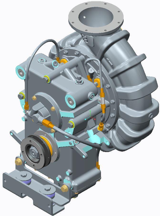

1 INSTALLATION OF TYPE ZSP PTO DRIVEN Fire Pump
2 Important Rotating shafts can be dangerous. Clothes, skin, hair, hands, etc. can become snagged or tangled, causing serious injury or death. Do not work on a driveshaft or pump when the engine is running or without the wheels chocked. Great care must be taken in the layout of pump drivelines. Interference and driveline vibration must be considered. An experienced installer with knowledge of driveline considerations, proper layout and recommended guidelines should be utilized as well as proper CAD systems for driveline layouts. Installation of the driveline should not occur until a proper analysis is performed by either a qualified driveline specialist or W.S. Darley. W.S. Darley utilizes, can distribute and can train qualified individuals to use the Allison Multiple Joint Driveline Analysis program. W.S. Darley requires that Power Take Off (PTO) driven pumps have at most 500 radians per second 2 torsional vibration and at most 1000 radians per second 2 inertial drive torsional vibration, as calculated by the Allison Multiple Joint Driveline Analysis program, for a completed driveline installation. A completed driveline installation includes the entire multidriveshaft assembly from the power source of the PTO output flange to the input flange of the PTO driven pump. Failure to design and analyze a proper driveline layout could result in severe injury and damage to equipment, including but not limited to: the water pump, the water pump transmission, drive tubes, hanger bearings, u-joint crosses, gears, the rear differential, and the main truck transmission. Exposed rotating drive-shafts should be guarded. It is highly recommended by Darley to use safety rings around drive tubes. Especially near connecting u-joint crosses. Such safety rings would be sufficiently attached to the chassis frame and sufficiently strong enough to prevent a broken u-joint assembly from allowing a driveline to slide out from underneath the truck at high speeds while still rotating, causing severe personnel injury. Said safety rings would be larger than the drive tube OD and provide enough clearance for dynamic non-rotational movement of the drivelines through loaded and unloaded conditions, driving operations and where chassis flex may occur.
3 U-Joints: - Universal joints must always be installed in pairs to transmit uniform rotary motion. - The operating angles of each universal joint in the pair should be as close to equal as possible. - The input and output shafts of each universal joint pair may be either parallel, or so located that the centerline of each shaft intersects the midpoint of the shaft connecting each universal joint (intersecting angles). o This arrangement may be required if the coupling shaft between pump and PTO is relatively short, or the engine is mounted with its driveshaft horizontal. Refer to attached drawing DGM1301 for examples of parallel shaft and intersecting angle installations. o DGM1301 shows a midship split shaft style pump, but the same installation recommendation/information applies to PTO s and PTO driven pumps. See the appendix of this portion of the manual for the Spicer Driveline Installation Guide (J DSSP)
4
5 Driveline and Mounting: Determine the best location for the pump in your chassis. Allow adequate room for pump maintenance. Place the pump/cross-member assembly on the chassis frame at the desired location. Be sure to set the suction manifold and transmission support brackets at a position allowing the best possible operating angle and driveline performance. This can be done by drilling frame rail mounting holes in a manner to rotate the entire pump/transmission assembly at an angle. As well up and down positioning is important. Measure the vertical angle between the truck PTO shaft centerline and chassis frame (often 4 o ). Suspend the pump so that the pump driveshaft centerline is as close as possible to being inline and parallel to the truck PTO shaft centerline. Example: If the truck PTO is at 4 o with horizontal, the pump driveshaft should also be set at 4 o with horizontal. This will insure that even if the PTO and pump are offset from each other, the universal joint operating angles will be equal. Check to confirm that the pump shaft is parallel to the PTO shaft.
6 Place suction manifold mounting brackets into position as shown on detail drawing DGM2902 and securely clamp against side of frames. Attach brackets to the suction extensions with pipe U-bolts. One of the two suction manifold brackets must be free to pivot as seen in drawing DGM1302. Choose one side of the frame or the other for the location of the pivot, the opposite must be rigidly secured with (2) 5/8 fasteners. Drill holes through the side frames and attach the mounting brackets. Note both mounting brackets are designed to permit truck frame flex without imposing stress on pump extensions.

7 Reference drawing DGM2908 for the KM02102 and KM02103 bracket assembly locations on the ZSP.
8 Assembly KM02102, depicted by drawing DGM2905, is the vibration isolating mounting bracket that attaches to the pump s suction head.
9 Assembly KM02103, depicted by drawing DGM2906, is the vibration isolating mounting bracket that attaches to the pump s gearbox.
10 The bracket is item 2 from both the KM02102 and KM02103 assemblies is the item that the customer will have to attach their own fabricated bracketing and cross members to for securing the ZSP back to the apparatus frame rails. If need be, customers can fabricate their own bracket to replace the bracket from within the KM02103 or KM02103 assemblies. The bracket is intended to be secured with 1/2 fasteners or welded back to the customers bracketing and cross members.
11 Reference drawing and for vibration isolating mounts and washers for adapting the mounting brackets to attach to the customer s supplied cross member or bracketing. Snubbing Washer Side IMPORTANT: These rubber isolators are a two piece design. The loading on these isolation mounts is cantilevered in this application (i.e. the center of gravity of the transmission and pump assembly is not directly above the centerline of the rubber isolators, it is offset), therefore the snubbing washer (see on the next page) should be on the core/bushing side of the rubber isolator (see below images). Therefore the snubbing washer should be on top of the smaller rubber section of the isolator, not the ring portion. So, for this application the stack-up from top to bottom should be as follows: bolt head, snubbing washer, core/bushing side of isolator, transmission mount bracket, ring portion of isolator, customer supplied cross member, nut or lock nut. Torsional loading should never be placed on the ring portion of the isolator.
12 Core/Bushing of Rubber Isolator Ring Portion of Rubber Isolator Core/Bushing of Rubber Isolator
13 Drill holes through the apparatus frame rails and attach necessary mounting brackets and cross members. Note, the KM02102 and KM02103 mounting bracket assemblies are designed to permit truck frame flexing without imposing stress on the pump. The installed brackets must be free to pivot as shown in drawing DGM1302. Choose one side of the frame or the other for the location of the pivot, the opposite must be rigidly secured with (2) 5/8 fasteners. Provide adequate support for all piping. Keep the following points in mind when positioning the pump and constructing the driveline. 1. Do not exceed recommended universal joint operating angles. Complimentary shaft angles should be equal and as low as possible. 2. Do not exceed universal joint torque limitations. 3. Do not exceed driveshaft speed/length limitations. 4. It is recommended that yokes on each end of a drive shaft be in phase. When in phase the yoke lugs (ears) at each end are in line. 5. Use balanced driveline components to help prevent vibration and to extend the life of drive yokes and other components related to the drive line.
14 Torque the universal joint bearing cap retaining bolts to the following Dana Spicer Recommendations: U-BOLT CAP & BOLT SERIES RECOMMENDED NUT TORQUE SERIES RECOMMENDED BOLT TORQUE LB. FT LB. FT LB. FT LB. FT LB. FT LB. FT LB. FT LB. FT LB. FT LB. FT LB. FT LB. FT LB. FT LB. FT LB. FT BEARING STRAP LB. FT SERIES RECOMMENDED BOLT TORQUE LB. FT SPL LB. FT LB. FT BEARING PLATE LB. FT SERIES RECOMMENDED BOLT TORQUE LB. FT LB. FT LB. FT LB. FT LB. FT LB. FT LB. FT LB. FT LB.FT LB.FT LB.FT LB.FT New part kits with lockstraps LB. FT available from Spicer LB. FT after Spring LB. FT SERIES RECOMMEND BOLT TORQUE LB. FT LB. FT LB. FT LB. FT LB. FT WARNING: Bearing strap retaining bolts must NOT be reused! WARNING: Self-locking bolts must NOT be reused! Note: The Dana Spicer fastener torque recommendations are per Dana Spicer s literature # DSD 4/94.
15 Lubricate universal joint cross using a good quality E.P. (extreme pressure) grease meeting N.L.G.I. E.P. Grade 2 specifications. (Consult your local lubricant source for greases that meet this specification. PRIMER CONNECTION: For 12/24-volt electrically-clutched belt-driven priming pump installation, see drawings DVC0306 through DVC0309 found in Section 4 - Pump Detail of the ZSP Installation, Operation, Maintenance, Repair and Troubleshooting Manual. ENGINE COOLING/PUMP HEATER: Two tapped openings in the pump suction head are provided for circulating engine coolant through the heater jacket/heat exchanger to prevent pump freezing in cold weather, and to aid in engine cooling in warm weather. Use no smaller than a 1/2 heater hose for this connection. See drawing DGS0400. An external heat exchanger should be added to aid in cooling the engine on units that do not have an internal heater jacket/heat exchanger in the suction head. PUMP SHIFT INSTALLATION: For power shift installation, refer to DGS1100 for automatic transmission wiring details.
INSTALLATION OF TYPE AG, HM, JMP, KSP, LSP, PSP, & OTHER PTO DRIVEN PUMPS
 INSTALLATION OF TYPE AG, HM, JMP, KSP, LSP, PSP, & OTHER PTO DRIVEN PUMPS Prepared by: EAS Rev. A Approved by: TED Date: 03/16/12 Revised by: CWY Rev. Date: 06/20/13 1201009.doc Important Rotating shafts
With PA Series Transmission: S101 Series Midship Pumps: With C20 Series Transmission:
 S100 Series C10 Chain Drive Transmission Overhaul Instructions Installation Instructions S100 Series Centrifugal Fire Pumps Issue Date Form No. F 1031 Section 3017 09/25/02 Rev. Date 04/26/13 IL3292 Table
Spicer Driveshaft Components Failure Analysis Guide
 Spicer Driveshaft Components Failure Analysis Guide Learn how to identify failed driveshaft components. Preventive Maintenance Driveshaft inspection should be performed as part of your regular maintenance.
97-06 JEEP TJ/LJ LONG ARM UPGRADE KIT
 921663U00 97-06 JEEP TJ/LJ LONG ARM UPGRADE KIT Thank you for choosing Rough Country for your suspension needs. This kit is an upgrade kit only. This kit includes frame mounting points and adjustable long
CL Series Centrifugal Fire Pumps Installation Instructions
 CL Series Centrifugal Fire Pumps Installation Instructions Table of Contents Safety Information... 1 Introduction... 2 Pump Mounting... 2 Pump Mounting-CLK Series (Optional Mounting Brackets) 3 Optional
MGA and RGA SERIES SPLIT-SHAFT PTO DRIVE GEARBOX INSTALLATION MANUAL
 11/07/2008 MGA and RGA SERIES SPLIT- PTO DRIVE GEARBOX All Hale products are quality components: ruggedly designed, accurately machined, precision inspected, carefully assembled and thoroughly tested.
WARNING THIS SYMBOL WARNS OF PERSONAL INJURY OR DEATH. Page 2
 WARNING ALWAYS READ AND UNDERSTAND THE ENTIRE MANUAL COMPLETELY BEFORE INSTALLATION OR OPERATION OF PTO AND DRIVEN EQUIPMENT INCLUDING THESE WARNINGS AND OPERATOR S INSTRUCTIONS IN SECTION 3! ALWAYS DISENGAGE
ASSEMBLY & INSTALLATION INSTRUCTIONS
 ASSEMBLY & INSTALLATION INSTRUCTIONS LSRH W.S. Darley & Company The installation instructions here within cover the best practice for safe installation, proper wiring, recommended pipe work, proper installation
TC Series Driveline. Table of Contents. TC Series Driveline
 TC Series Driveline Table of Contents Table of Contents...1 List of Figures...1 Safety...3 Warnings and Cautions...3 Inspection and Lubrication of Driveshaft...3 Inspection...3 Lubrication...5 Lubricants
RM SERIES PTO INSTALLATION AND OPERATOR S MANUAL KEEP IN VEHICLE FOR ALLISON TC10 READ OPERATING INSTRUCTIONS INSIDE BEFORE OPERATING PTO
 KEEP IN VEHICLE READ OPERATING INSTRUCTIONS INSIDE BEFORE OPERATING PTO RM SERIES PTO INSTALLATION AND OPERATOR S MANUAL FOR ALLISON TC10 Muncie Power Products, Inc. WARNING! ALWAYS READ AND UNDERSTAND
INSTALLATION INSTRUCTIONS
 INSTALLATION INSTRUCTIONS 8A000729 DuraLift 13.5 13,500 LB. CAPACITY Link Mfg. Ltd. 223 15th St. N.E. Sioux Center, IA USA 51250-2120 www.linkmfg.com QUESTIONS? CALL CUSTOMER SERVICE 1-800-222-6283 Refer
With WB Series Transmission: With PA Series Transmission: With K Series Transmission:
 Fire Pumps CG Series Centrifugal Fire Pumps Installation Instructions IL3214 Table of Contents Safety Information... 2 Introduction... 3 Pump Mounting: CGVG Series Pumps: With C20 Series Transmission:
E4-WM5-Y371A00 MOUNTING INSTRUCTION
 E4-WM5-Y371A00 MOUNTINGINSTRUCTION IMPORTANT! PLEASE READ ALL INSTRUCTIONS FIRST! If in doubt, please contact your local BILSTEIN dealer or our sales department before installation. When replacing other
HINO PTO INTERFACE PTO INSTALLATION AND OPERATOR S MANUAL KEEP IN VEHICLE. FOR Allison 2500 With CS6B-A67**-S3*H PTO
 KEEP IN VEHICLE READ OPERATING INSTRUCTIONS INSIDE BEFORE OPERATING PTO HINO PTO INTERFACE PTO INSTALLATION AND OPERATOR S MANUAL FOR Allison 2500 With CS6B-A67**-S3*H PTO Muncie Power Products, Inc. Important
INSTALLATION INSTRUCTIONS
 INSTALLATION INSTRUCTIONS --1075 North Ave. Sanger, CA 93657-3539 local: 559-875-0222 fax: 559-876-2259 toll free: 800-445-3767-- 6522 REAR AXLE FLIP & SHACKLE KIT 07-UP CHEVROLET 1500 REGULAR CAB ONLY
INSTALLATION INSTRUCTIONS
 INSTALLATION INSTRUCTIONS 6525 REAR AXLE FLIP & HANGER KIT 5 OR 6 INCH LOWERING 14&UP CHEVROLET SILVERADO / GMC SIERRA 1500 Thank you for being selective enough to choose our high quality BELLTECH PRODUCT.
TRAILER INSTALLATION INSTRUCTIONS
 TRAILER INSTALLATION INSTRUCTIONS 8A000450 DuraMax 20,000 LB. CAPACITY Link Mfg. Ltd. 223 15th St. N.E. Sioux Center, IA USA 51250-2120 www.linkmfg.com QUESTIONS? CALL CUSTOMER SERVICE 1-800-222-6283 Refer
PROPELLER SHAFTS 16-1 PROPELLER SHAFTS CONTENTS
 Z PROPELLER SHAFTS 16-1 PROPELLER SHAFTS CONTENTS page GENERAL INFORMATION... 1 PROPELLER SHAFT REPLACEMENT... 7 SERVICE DIAGNOSIS/PROCEDURES... 3 page TORQUE SPECIFICATIONS... 14 UNIVERSAL JOINT REPLACEMENT...
MS2200, MS2500, and MS3000 Suspension Installation Manual ON/OFF HIGHWAY SUSPENSION SYSTEM
 MS22, MS25, and MS3 Suspension Installation Manual ON/OFF HIGHWAY SUSPENSION SYSTEM 972.547.62 8.445.736 FAX: 972.542.97 725 E. UNIVERSITY ST. McKINNEY, TEXAS 7569 www.watsonsuspensions.com Watson & Chalin
Drilling Series SC Series Cellular Suction Stabilizers Instruction, Operating & Maintenance Manual
 Drilling Series SC Series Cellular Suction Stabilizers Instruction, Operating & Maintenance Manual Manufacturer of Pulsation Control Products 3309 Essex Dr. Suite 200, Richardson, Texas 75082 Phone: 972.699.8600
SELKIRK CORP INSTALLATION INSTRUCTION SUPPLEMENT MODEL G - CHIMNEY LINER
 SELKIRK CORP MODEL G - CHIMNEY LINER These instructions are supplemental to the General Installation Instructions for Selkirk Model G, PS, IPS and ZC Single Wall, Double Wall Air & Fiber Insulated Positive
"Engineered to Ride, Built to Last "
 Congratulations on your purchase of an Arnott air suspension product. We at Arnott Incorporated are proud to offer a high quality product at the industry s most competitive pricing. Thank you for your
ATTENTION: PLEASE READ AND UNDERSTAND ALL INSTRUCTIONS AND WARNINGS BEFORE ASSEMBLING, INSTALLING OR USING THIS PRODUCT. PRODUCT REGISTRATION WARNING
 VAN STORAGE SOLUTIONS FOR THE WAY YOU WORK TM INSTALLATION MANUAL SLIDING LADDER RACK Model 250 ATTENTION: PLEASE READ AND UNDERSTAND ALL INSTRUCTIONS AND S BEFORE ASSEMBLING, INSTALLING OR USING THIS
TC20 Chain Driven Power Take-Off Overhaul Instructions
 TC20 Chain Driven Power Take-Off Overhaul Instructions Table of Contents Section Page Introduction 4 Ordering Repair Parts 4 General Information 5 Special Tools 6 Disassembly See Page 2 Reassembly See
<THESE INSTRUCTIONS MUST BE GIVEN TO THE END USER> B&W
 B&W Trailer Hitches 1216 Hawaii Rd / PO Box 186 Humboldt, KS 66748 Turnoverball Gooseneck Hitch Installation Instructions MODEL 1314 2013 2014 RAM 3500
QTY 3D PART NO. DESCRIPTION
 QTY 3D PART NO. DESCRIPTION 1 691032 V6 FRONT AIR DAM 1 691023 SIDE SKIRT RIGHT 1 691024 SIDE SKIRT LEFT 1 691566 V6 DUAL EXHAUST REAR LOWER SKIRT- 8 3M 94 3M ADHESION PROMOTER 24 #8 X ¾ SELF DRILLING
Models: DC Electric Vibrators. Operating Instructions CEG CEG CEG CEG CEG CEG
 DC Electric Vibrators Operating Instructions Global External bin & hopper 12 & 24 Volt DC Electric Vibrators Models: CEG-400-12 CEG-800-12 CEG-1200-12 CEG-400-24 CEG-800-24 CEG-1200-24 Global Manufacturing
<THESE INSTRUCTIONS MUST BE GIVEN TO THE END USER> B&W
 B&W Trailer Hitches 1216 Hawaii Rd / PO Box 186 Humboldt, KS 66748 P:620.473664 F:620.869.9031 Turnoverball Gooseneck Hitch Installation Instructions
<THESE INSTRUCTIONS MUST BE GIVEN TO THE END USER> B&W
 B&W Trailer Hitches 6 Hawaii Rd / PO Box 86 Humboldt, KS 6678 P:60.7366 F:60.86.03 Turnoverball Gooseneck Hitch Installation Instructions MODEL 38 0 08
PRODUCT USE INFORMATION
 921655300 Thank you for choosing Rough Country for your suspension needs. *65530BAG1* 65530BAG1 JEEP JL 3.5 Adj. Lower Control Arm Kit Rough Country recommends a certified technician install this system.
LR-3510 Install and Operation Manual
 RUGBY MANUFACTURING CO. INDUSTRIAL PARK 515 1st St. NE. RUGBY, NORTH DAKOTA 58368 03 6048 Install and Operation Manual LATEST EDITION: 1st (January 4, 2001) FIRST EDITION: January 4, 2001 Page 2 of 9 WARNINGS:
PTO INSTALLATION & OPERATOR S MANUAL
 PTO INSTALLATION & OPERATOR S MANUAL EX-DRIVE Shaft Extension KEEP IN VEHICLE READ OPERATING INSTRUCTIONS INSIDE BEFORE OPERATING PTO Muncie Power Products, Inc., Member of Interpump Group TABLE OF CONTENTS
Jeep Grand Cherokee ZJ 4 Suspension Kit
 92168800 Jeep Grand Cherokee 93-98 ZJ 4 Suspension Kit Thank you for choosing Rough Country for all your suspension needs. Rough Country recommends a certified technician install this system. In addition
TT-15 INSTALLATION INSTRUCTIONS SHOWN WITH OPTIONAL 2 PC. ALUMINUM PLATFORM AND LIGHT KIT
 TM TOPLIFTER Tailgates By THIEMAN TT-15 INSTALLATION INSTRUCTIONS SHOWN WITH OPTIONAL 2 PC. ALUMINUM PLATFORM AND LIGHT KIT! IMPORTANT! KEEP IN VEHICLE! PLEASE READ AND UNDERSTAND THE CONTENTS OF THIS
97-06 JEEP TJ 3 1/4 PROGRESSIVE COIL/SPACER KIT
 92PERF1641 97-06 JEEP TJ 3 1/4 PROGRESSIVE COIL/SPACER KIT Thank you for choosing Rough Country for your suspension needs. Rough Country recommends a certified technician installs this system. In addition
Suspension System RS6507B (Rubicon models require end link kit RS6753B for a complete installation)
") 88507 Rev G Suspension System RS6507B (Rubicon models require end link kit RS6753B for a complete installation) Jeep Wrangler (JK) 88507 Rev G READ ALL INSTRUCTIONS THOROUGHLY FROM START TO FINISH BEFORE
88507 Rev G Suspension System RS6507B (Rubicon models require end link kit RS6753B for a complete installation) Jeep Wrangler (JK) 88507 Rev G READ ALL INSTRUCTIONS THOROUGHLY FROM START TO FINISH BEFORE
IMPORTANT! PLEASE READ ALL INSTRUCTIONS FIRST!
 A00 MOUNTINGINSTRUCTION IMPORTANT! PLEASE READ ALL INSTRUCTIONS FIRST! If in doubt, please contact your local BILSTEIN dealer or our sales department before installation. When replacing other brands, BILSTEIN
Jeep Wrangler (JK) Present
 Present") Suspension System RS66110B (3 SPORT SYSTEM w/ Progressive Coil Springs Front & Rear) 2012 NEWER JEEP MODELS EQUIPPED WITH 3.6L V6 ENGINE NEED EXHAUST MODIFICATION KIT RS720003. OR REPLACEMENT FRONT DRIVESHAFT
Suspension System RS66110B (3 SPORT SYSTEM w/ Progressive Coil Springs Front & Rear) 2012 NEWER JEEP MODELS EQUIPPED WITH 3.6L V6 ENGINE NEED EXHAUST MODIFICATION KIT RS720003. OR REPLACEMENT FRONT DRIVESHAFT
6 Suspension System. Dodge wd Part#:
 Part#: 012622 6 Suspension System Dodge 2500 4wd 2009-2013 Rev. 010218 491 W. Garfield Ave., Coldwater, MI 49036. Phone: 517-279-2135 E-mail: tech-bds@sporttruckusainc.com Read And Understand All Instructions
TL INSTALLATION MANUAL FOR TELMA AF50-90 with ROTARY FOOT SWITCH DESIGN 2 FORD F550 CAB CHASSIS FROM MODEL YEAR 2011
 INSTALLATION MANUAL FOR TELMA AF50-90 with ROTARY FOOT SWITCH DESIGN 2 FORD F550 CAB CHASSIS FROM MODEL YEAR 2011 1sep16jh TABLE OF CONTENTS 1 Preparation of the Chassis 1.1 Driveline 1.2 Exhaust 1.3 Fuel
JEEP JK 6 2 DR X-SERIES SUSPENSION KIT
 921684X00 Thank you for choosing Rough Country for your suspension needs. JEEP JK 6 2 DR X-SERIES SUSPENSION KIT Rough Country recommends a certified technician install this system. In addition to these
97-06 JEEP TJ / LJ 2 1/2 LONG ARM KIT W/ PERFORMANCE 2.2 SERIES SHOCK ABSORBERS
 92PERF1628 97-06 JEEP TJ / LJ 2 1/2 LONG ARM KIT W/ PERFORMANCE 2.2 SERIES SHOCK ABSORBERS Thank you for choosing Rough Country for your suspension needs. Rough Country recommends a certified technician
OPERATORS MANUAL FOR KAFURTER ROTARY TOPPERS MODELS: TP110, TP140, TP160, TP170
 OPERATORS MANUAL FOR KAFURTER ROTARY TOPPERS MODELS: TP110, TP140, TP160, TP170 SAFETY WARNING: Do not use or operate this this manual and assembly instructions (where applicable) has been read and understood.
Installation and Maintenance Instructions Falk Wrapflex (Page 1 of 7) 1. General Information. 2. Safety and Advice Hints DANGER! Type 10R.
 1. General Information. 2. Safety and Advice Hints DANGER! Type 10R.") (Page 1 of 7) This is the Original Document in English Language Type 10R Type 31R Type 35R Figure 1 - Wrapflex coupling range 1. General Information 1.1. Falk Wrapflex Couplings are designed to provide
(Page 1 of 7) This is the Original Document in English Language Type 10R Type 31R Type 35R Figure 1 - Wrapflex coupling range 1. General Information 1.1. Falk Wrapflex Couplings are designed to provide
MITSUBISHI MQ L200 AND FIAT FULLBACK Suspension Installation Instructions
 INSTALLATION GUIDE MITSUBISHI MQ L200 AND FIAT FULLBACK 2015+ Suspension Installation Instructions NOTE: Occupational Health & Safety procedures must be observed at all times. IMPORTANT: Installations
Jeep Wrangler (JK)
") 89109 Rev B Suspension Systems RS66109BR5 and RS66109BR9 2007 2013 Jeep Wrangler 4 Door Sport and Rubicon Models (2 SPORT SYSTEM) Jeep Wrangler (JK) 2007-2013 89109 Rev B READ ALL INSTRUCTIONS THOROUGHLY
89109 Rev B Suspension Systems RS66109BR5 and RS66109BR9 2007 2013 Jeep Wrangler 4 Door Sport and Rubicon Models (2 SPORT SYSTEM) Jeep Wrangler (JK) 2007-2013 89109 Rev B READ ALL INSTRUCTIONS THOROUGHLY
<THESE INSTRUCTIONS MUST BE GIVEN TO THE END USER> B&W Trailer Hitches 1216 Hawaii Rd / PO Box 186 Humboldt, KS P: F:
 B&W Trailer Hitches 6 Hawaii Rd / PO Box 86 Humboldt, KS 6678 P:60.7366 F:60.73766 Turnoverball Gooseneck Hitch Installation Instructions MODEL 38 0 06
Railgates By THIEMAN VL-30, 40, 50 PLEASE READ AND UNDERSTAND THE CONTENTS OF THIS MANUAL BEFORE OPERATING THE EQUIPMENT. HIEMAN
 VL SERIES Railgates By THIEMAN VL-30, 40, 50 INSTALLATION INSTRUCTIONS! IMPORTANT! KEEP IN VEHICLE! PLEASE READ AND UNDERSTAND THE CONTENTS OF THIS MANUAL BEFORE OPERATING THE EQUIPMENT. NATIONAL TRUCK
PROJ. NO SECTION HYDRONIC PUMPS
 SECTION 23 21 23 HYDRONIC PUMPS PART 1 - GENERAL 1.1 RELATED DOCUMENTS A. Drawings and general provisions of the Contract, including General and Supplementary Conditions and Division 01 Specification Sections,
2-row and All-row systems included.
 Ag Leader Technology Cotton Picker Installation Installation Instructions for John Deere cotton picker models: 2-row and All-row systems included. IMPORTANT: Ensure the model numbers shown above correspond
INSTALLATION INSTRUCTIONS
 INTRODUCTION Installation requires a professional mechanic. Prior to beginning, inspect the vehicles steering, driveline, and brake systems, paying close attention to the suspension link arms and bushings,
<THESE INSTRUCTIONS MUST BE GIVEN TO THE END USER> B&W
 B&W Trailer Hitches 6 Hawaii Rd / PO Box 86 Humboldt, KS 66748 P:60.473664 F:60.869.903 Turnoverball Gooseneck Hitch Installation Instructions MODEL 08
20 Gauge Super-Speed. shoprpmachine
 Operator tor s s manual 20 Gauge Super-Speed 1 WARRANTY Our guarantee on the products we manufacture is limited to repair or replacement without charge, of any part found to be defective in materials or
IMPORTANT! PLEASE READ ALL INSTRUCTIONS FIRST!
 MOUNTNG NSTRUCTON MPORTANT! PLEASE READ ALL NSTRUCTONS FRST! f in doubt, please contact your local BLSTEN dealer or our sales department before installation. When replacing other brands, BLSTEN shock absorbers
Post Hole Digger. Operation Manual MODEL
 Post Hole Digger MODEL 107798 Operation Manual This safety alert symbol identifies important safety messages in this manual. Failure to follow this important safety information may result in serious injury
"Engineered to Ride, Built to Last "
 Congratulations on your purchase of an Arnott air suspension product. We at Arnott Incorporated are proud to offer a high quality product at the industry s most competitive pricing. Thank you for your
NC State University Design and Construction Guidelines Division 23 Hydronic Pumps
 1.0 Purpose A. The following guidelines apply to the selection of pumps primarily for circulating water. It is the goal of NC State to purchase pumps that are selected to provide a long service life, minimal
SECTION V ASSEMBLY CAUTION THE FOLLOWING SAFETY PRECAUTIONS SHOULD BE THOROUGHLY UNDERSTOOD BEFORE ATTEMPTING MACHINE ASSEMBLY.
 SECTION V ASSEMBLY CAUTION THE FOLLOWING SAFETY PRECAUTIONS SHOULD BE THOROUGHLY UNDERSTOOD BEFORE ATTEMPTING MACHINE ASSEMBLY. 1. Wear personal protective equipment such as, but not limited to protection
"Engineered to Ride, Built to Last "
 Congratulations on your purchase of an Arnott air suspension product. We at Arnott Incorporated are proud to offer a high quality product at the industry s most competitive pricing. Thank you for your
Visit Our Our Our Web Site at:
 Visit Our Our Our Web Site at: ww w ww w w w w. l o c k f o rr r m e r r r. c o m 711 OGDEN AVENUE, LISLE, ILLINOIS 60532-1399 Phone (630) 964-8000 Fax (630) 964-5685 09-1998 Operator tor s manual 20 Gauge
TL INSTALLATION MANUAL FOR TELMA AC50-55 ON FORD E-350/450 CUTAWAY WITH TELMA CONTROL MODULE
 INSTALLATION MANUAL FOR TELMA AC50-55 ON FORD E-350/450 CUTAWAY WITH TELMA CONTROL MODULE 17feb12jh TABLE OF CONTENTS 1 Preparation of the Chassis 1.1 Driveline 1.2 Exhaust 2 Telma Installation 2.1 Installation
INSTALLATION INSTRUCTION 88578
 INSTALLATION INSTRUCTION 88578 For Rancho Suspension System RS6579B: 4WD Dodge 1500 & 2500 READ ALL INSTRUCTIONS THOROUGHLY FROM START TO FINISH BEFORE BEGINNING INSTALLATION Rev E IMPORTANT NOTES! WARNING:
IMPORTANT WARRANTY & INSTALLATION INSTRUCTIONS ATTACHED
 IMPORTANT WARRANTY & INSTALLATION INSTRUCTIONS ATTACHED Please Forward All Attached Information to Consumer Warranty Not Valid Unless Returned to CORSA Exhaust STOP Please take time to read and understand
6 Suspension System. Dodge wd Part#: &
 Part#: 012621 & 012631 6 Suspension System Dodge 2500 4wd 2008-2009 Rev. 010218 491 W. Garfield Ave., Coldwater, MI 49036. Phone: 517-279-2135 E-mail: tech-bds@sporttruckusainc.com Read And Understand
Post Hole Diggers Compact Standard Heavy Duty
 Post Hole Diggers Compact Standard Heavy Duty MODEL 90 / MODEL 100 / MODEL 110 # 100623 # 100498 # 100624 Operation Manual This safety alert symbol identifies important safety messages in this manual.
TL INSTALLATION MANUAL FOR TELMA AF50-55 ON FORD E-350/450 CUTAWAY with rotary foot switch design 2 including MY2016 changes
 INSTALLATION MANUAL FOR TELMA AF50-55 ON FORD E-350/450 CUTAWAY with rotary foot switch design 2 including MY2016 changes 10nov16jh TABLE OF CONTENTS 1 Preparation of the Chassis 1.1 Driveline 1.2 Exhaust
PRODUCT USE INFORMATION
 921654300 Thank you for choosing Rough Country for your suspension needs. *65430BAG1* 65430BAG1 JEEP JL 3.5 Control Arm Drop Suspension Kit Rough Country recommends a certified technician install this
Version VDL Weweler b.v. Maintenance & Installation Manual
 Version 1.3 18-8-2014 VDL Weweler b.v. Maintenance & Installation Manual CONTENTS 1. Introduction 2 2. Maintenance work 3 - Overview - Air springs - Shock absorbers - U-Bolts - Pivot Bolts - Air spring
Models: DC Electric Vibrators. Operating Instructions CEG CEG CEG CEG CEG
 DC Electric Vibrators Operating Instructions Global External 12-Volt DC Electric Vibrators Intermittent Use Only Models: CEG-1800-12 CEG-2200-12 CEG-2800-12 CEG-3600-12 CEG-4200-12 INDUSTRIAL ELECTRIC
DO NOT GRIND ANY WELDS
 1 READ FIRST! PLEASE READ THROUGH ALL OF THE INSTRUCTIONS AND ENSURE THAT YOU UNDERSTAND THEM. BE SURE THAT YOU HAVE ALL THE REQUIRED GSI COMPONENTS, BASIC TOOLS, AND SKILLS. CUTTING THIS KIT REQUIRES
INSTALLATION INSTRUCTIONS FOR: RE DOOR JK WRANGLER RE DOOR JK WRANGLER 3.5 STANDARD SUSPENSION SYSTEM
 RUBICON MANUFACTURING INC. 3290 MONIER CIR., RANCHO CORDOVA, CA. 95742 916-473-4600 INSTALLATION INSTRUCTIONS FOR: RE7122 2 DOOR JK WRANGLER RE7142 4 DOOR JK WRANGLER 3.5 STANDARD SUSPENSION SYSTEM Safety
Suspension System RS66102B
 890 Rev A Suspension System RS660B ( SPORT SYSTEM) 0 JEEP MODELS EQUIPED WITH 3.6L V6 ENGINE NEED EXHAUST MODIFYCATION KIT RS70003. OR REPLACEMENT FRONT DRIVESHAFT (DRIVESHAFT / EXHAUST CLERANCE ISSUE).
SECTION PUMPS GENERAL PUMPS PART RELATED DOCUMENTS
 SECTION 15160 - PUMPS PART 1 - GENERAL 1.01 RELATED DOCUMENTS A. Basic Requirements: Provisions of Section 15010, BASIC MECHANICAL REQUIREMENTS and Section 15030, ELECTRICAL REQUIREMENTS FOR MECHANICAL
Spicer Driveshafts. Service Manual. DSSM3264 September 2007
 Spicer Driveshafts Service Manual DSSM3264 September 2007 Table of Contents Safety...................... 1 General Safety.......................... 1 Component Safety...................... 2 Driveline...........................
IMPORTANT WARRANTY & INSTALLATION INSTRUCTIONS ATTACHED
 IMPORTANT WARRANTY & INSTALLATION INSTRUCTIONS ATTACHED Please Forward All Attached Information to Consumer Warranty Not Valid Unless Returned to CORSA Performance We ask that you take a few moments to
"Engineered to Ride, Built to Last "
 Congratulations on your purchase of an Arnott air suspension product. We at Arnott Incorporated are proud to offer a high quality product at the industry s most competitive pricing. Thank you for your
Cable Management System Installation Manual
 Cable Management System Installation Manual TABLE OF CONTENTS 1.0 INTRODUCTION and SAFETY... 2 2.0 INSPECTION and UNPACKING... 2 3.0 GENERAL INSTALLATION... 2 4.0 UPPER MOUNTING... 5 4.1 Under Hung Loft
tRIPr Chief Grain Cart. Operator s Manual. Operator s Manual
 125-000-01 125-000-01 1tRIPr 1tRIPr Operator s Manual 1210 Chief Grain Cart Operator s Manual Operator s Manual TO THE DEALER Predelivery/Delivery Checklist 1210 Grain Cart PREDELIVERY/DELIVERY CHECKLIST
Rostselmash Torum 740
 Note: Indented items indicate parts included in an assembly listed above Quantity by Model Part Name/Description Part Number 740 Combine Kit Torum 740 4100762 1 Threaded Arm Assembly 2000311-2 1 Header
TRANSMISSION INSTALLATION CONTENTS
 A REGAL-BELOIT Company TRANSMISSION INSTALLATION CONTENTS RICHMOND 6-SPEED TRANS AM, CAMARO, CHEVELLE, GTO, CUTLASS, WITH T-10/MUNCIE............2 RICHMOND 6-SPEED 1963 TO 1982 CORVETTE WITH T-10 OR MUNCIE..............................3
Suspension System RS6509B
 88509 Rev H Requires the following for a complete installation: Quick disconnect end link kit RS6756B or solid end link kit RS6753B (for the Rubicon) Rancho exhaust kit RS720001 or RS720002 (or equivalent)
Suspension System RS6582B
 Suspension System RS6582B Tahoe/Yukon READ ALL INSTRUCTIONS THOROUGHLY FROM START TO FINISH BEFORE BEGINNING INSTALLATION IMPORTANT NOTES! WARNING: This suspension system will enhance the off-road performance
Suspension Upgrade System RS66152 (Upper Adjustable Control Arms)
") 89152 Rev B Suspension Upgrade System RS66152 (Upper Adjustable Control Arms) Fits 1997-2006 Jeep Wrangler (TJ / LJ). 89152 Rev B READ ALL INSTRUCTIONS THOROUGHLY FROM START TO FINISH BEFORE BEGINNING
89152 Rev B Suspension Upgrade System RS66152 (Upper Adjustable Control Arms) Fits 1997-2006 Jeep Wrangler (TJ / LJ). 89152 Rev B READ ALL INSTRUCTIONS THOROUGHLY FROM START TO FINISH BEFORE BEGINNING
»Product» Safety Warning
 Zone C2350 Installation Instructions 2007-2013 Chevy 1500 3.5" Lift Read and understand all instructions and warnings prior to installation of product and operation of vehicle. Zone Offroad Products recommends
ONLY AFTER ALL MEASUREMENTS HAVE BEEN TAKEN. Remove any components in the chassis that may interfere with the retarder and/or mounting hardware.
 Tools Needed Transmission jack Hand held calculator Mechanics hand tools Torque wrench (up to 250 lb.-ft) ½ heavy duty drill or frame drill Tape measure Straight edge Electronic Angle meter (Spicer Anglemaster
Suspension System RS66107 / RS66107B
 89107 Rev D Suspension System RS66107 / RS66107B (3 TRAIL SYSTEM) 2012 JEEP MODELS EQUIPPED WITH 3.6L V6 ENGINE NEED EXHAUST MODIFICATION KIT RS720003. OR REPLACEMENT FRONT DRIVESHAFT (DRIVESHAFT / EXHAUST
Operator s Manual Table of Contents For Darley PTO Driven JMH Fire Pump
 Operator s Manual Table of Contents For Darley PTO Driven JMH Fire Pump Description, Operation & Maintenance, & Lubrication---------------------------------------------- 1200570 Related Drawings --------------------------------------------------------------------------------------------
E46 REAR Subframe Reinforcement Repair KIT
 INSTRUCTIONS BMW E46 323i,325i,328i,330i,M3 1999-2006 E46 REAR Subframe Reinforcement Repair KIT Tools Needed: -Qualified tech and welder -Lift -Die Grinders -Basic tools -Caulking, primer and paint -Marker
GM WD P/U 6-LUG, AND ½ TON SUV S (CLASSIC BODY) W/ TORSION BARS SUSPENSION LIFT KIT KIT# TM106
 W/ TORSION BARS SUSPENSION LIFT KIT KIT# TM106") GM 1500 4WD P/U 6-LUG, AND ½ TON SUV S (CLASSIC BODY) W/ TORSION BARS SUSPENSION LIFT KIT 1988 2011 KIT# TM106 Installation of a Trail Master suspension lift kit will change the vehicle s center of gravity
GM 1500 4WD P/U 6-LUG, AND ½ TON SUV S (CLASSIC BODY) W/ TORSION BARS SUSPENSION LIFT KIT 1988 2011 KIT# TM106 Installation of a Trail Master suspension lift kit will change the vehicle s center of gravity
AEV30213AF Last Updated: 05/24/18. jk wrangler dualsport sc suspension right hand drive INSTALLATION GUIDE
 AEV30213AF Last Updated: 05/24/18 jk wrangler 3.5 4.5 dualsport sc suspension right hand drive INSTALLATION GUIDE PLEASE READ BEFORE YOU START TO GUARANTEE A QUALITY INSTALLATION, WE RECOMMEND READING
INSTALLATION INSTRUCTION 88092
 INSTALLATION INSTRUCTION 88092 FOR RANCHO SUSPENSION SYSTEM RS6592: NISSAN XTERRA & 2WD FRONTIER READ ALL INSTRUCTIONS THOROUGHLY FROM START TO FINISH BEFORE BEGINNING INSTALLATION Rev C IMPORTANT NOTES!
INSTALLATION INSTRUCTION 88148
 INSTALLATION INSTRUCTION 88148 Rev C For Rancho Suspension Systems RS6548, RS6549 & RS6550: GM 2500HD, 2500, and 1500HD Trucks READ ALL INSTRUCTIONS THOROUGHLY FROM START TO FINISH BEFORE BEGINNING INSTALLATION
»Product» Safety Warning
 #F2622 Installation Instructions 1997-2003 Ford F-150 4WD 6" Suspension System Read and understand all instructions and warnings prior to installation of product and operation of vehicle. Zone Offroad
Installation Instructions
 Installation Instructions For 3500HD & IMPORTANT NOTE The Axle Less suspension provides many advantages and permits many innovative designs for trailers. There is no thru axle and therefore the two sides
TOYOTA PRADO 150 Series Suspension Installation Instructions. NOTE: Occupational Health & Safety procedures must be observed at all times.
 INSTALLATION GUIDE TOYOTA PRADO 150 Series 2009+ Suspension Installation Instructions NOTE: Occupational Health & Safety procedures must be observed at all times. IMPORTANT: Installations should only be
Centrifugal PTO Pumps. 2 nd Edition
 Centrifugal PTO Pumps 2 nd Edition MAN072 November 2005 2005 Centrifugal PTO pumps are manufactured by AMADAS Industries. You can find us on the Web at: www.amadas.com or e-mail us at: amadas@amadas.com
IMPORTANT WARRANTY & INSTALLATION INSTRUCTIONS ATTACHED
 IMPORTANT WARRANTY & INSTALLATION INSTRUCTIONS ATTACHED Please Forward All Attached Information to Consumer Warranty Not Valid Unless Returned to CORSA Exhaust STOP Please take time to read and understand
»Product» Safety Warning
 J1455, J1456 Installation Instructions 1984-2001 Jeep Cherokee XJ 4.5 Suspension Lift Read and understand all instructions and warnings prior to installation of product and operation of vehicle. Zone Offroad
INSTALLATION INSTRUCTION 88051
 INSTALLATION INSTRUCTION 88051 For Rancho Suspension System RS6551: Chevrolet 2500 Suburban & 2500 Avalanche READ ALL INSTRUCTIONS THOROUGHLY FROM START TO FINISH BEFORE BEGINNING INSTALLATION Rev C IMPORTANT
IMPORTANT! PLEASE READ ALL INSTRUCTIONS FIRST!
 IMPORTANT! PLEASE READ ALL INSTRUCTIONS FIRST! If in doubt, please contact your local BILSTEIN dealer or our sales department before installation. When replacing other brands, BILSTEIN shock absorbers