SM1700 Pneumatic Center Punch Tool Owner s Manual and Operating Instructions
|
|
|
- Daniel Quinn
- 5 years ago
- Views:
Transcription

1 Owner s Manual and Operating Instructions Table of Contents Page Information 2 Warranty and Safety Guidelines 3 Overview and Installation 4 Air System Requirements 5 Setting Controls 6 Installing Clamps 7 Trouble Shooting Guide 8 Preventative Maintenance 9 Head Information 10 Gripper Assembly Replacement/Service Parts Identification 17 Air Connection Diagram 18 Factory Services
2 Warranty and Safety Warranty: For Warranty information visit the following URL Safety Guidelines: /Warranty.html Read this manual and become familiar with the tool before installing any clamps. Protective eyewear should be worn when connecting and disconnecting the tool to compressed air sources and during operation. Wear appropriate gloves for handling steel while operating this tool, applying steel clamps and removing the scrap clamp tail. should be firmly mounted before installing clamps. Clamp tensioning or clamp tail retrieval can be immediately stopped by releasing pressure from the foot pedal. When applying clamps, care should be taken to insure fingers and loose clothing are not in the way of the clamp being applied. Never attempt to clamp objects which have the potential to burst, shatter or otherwise cause bodily harm. Disconnect air supply prior to maintenance and disassembly of tool components. Important advice and warning to user, Read before applying clamps: The type clamp s lock and cut-off is achieved using considerable impact. This may cause damage to the object being clamped. Remember that a tighter clamp keeps the fitting more secure, but excess tension could damage the hose or fitting. Fitting stem must have prominent barbs for proper retention inside the hose, but barbs must not be sharp to prevent cutting into the hose. Hose, fitting and clamps must be compatible with each other and the intended working environment. If in doubt, consult the hose or fitting manufacturer or call BAND-IT. Clamping objects other than hose require similar precautions. CAUTION: Improperly tightened clamps may result in dangerous hose assemblies, which could cause injuries or property damage. CAUTION: Abuse or use of hose outside the manufacturer s recommended conditions may cause it to quickly deteriorate and become a safety hazard. This could result in serious injury or property damage. Inspect and test hose assemblies frequently. Repair or replace at the slightest sign of damage or deterioration
3 Overview and Installation Overview: The has been designed to automatically tension, lock and cut-off scrap tails of CP style clamps. Type 201 Stainless Steel and Galvanized Carbon Steel, 5/8 wide CP style clamps can be easily installed on hose assemblies or objects chosen by the operator. The will sense when the desired clamp tail tension is achieved and automatically switch to finalize the clamp. The completion of each clamp includes setting the lock while simultaneously cutting off the excess clamp tail without requiring an assembly roll-up action. Operating tip: Choose a clamp diameter close to the size of the diameter of the object being clamped. An oversized clamp may cause the End-of-Stroke safety switch to activate and prevent finalizing the clamp with a lock and cut-off (see page 6, #6 and page 7, #4). The directs compressed air through a foot pedal control to cycle the tool and complete the installation of BAND-IT Clamps. The foot pedal has a dual action, forward (toe) and reverse (heel). During normal operation, the operator should fully depress the foot pedal forward (toe), not removing this pedal pressure until the cycle has completed and clamp tail is ready to be removed from the tool. Upon completion of the tension, lock and cut-off cycle, the operator should depress the heel end of the pedal and remove the scrap clamp tail from the CP head. Operating tip: Operation can be stopped at any time by removing the operator s foot completely from the foot pedal control. Installation: 1. Recommended work bench height is This height is suggested as the optimum range for operator comfort and safety during typical clamp applications. Locate the tool on a solid surface making sure of ample clearance on either side for handling hose assemblies of various lengths. 2. The air tool must be firmly secured as close to the front edge of the work bench as possible. This will reduce interference of hose assemblies during clamp application. Install tool using 5/16 diameter fastening hardware (not supplied with tool). 3. Use of the without properly maintained filtration and lubrication will void the warranty. See page 4 for additional information on air supply requirements

4 Air System Requirements Important: For proper tool performance, follow air requirements for : Line Pressure 70 psi minimum,120 psi maximum ( kg/cm^2, kpa). Volume CFM Air Delivery system - ¼ minimum diameter air line with a ¼ N.P.T. connection. Filtration Follow typical filtration requirements of air operated equipment. The BAND-IT supplied system includes a filter and lubricator. Lubrication - Use DTE 24 hydraulic oil (BAND-IT part # S31589), oil drip-rate is verified by cycling the machine. If one drop falls in sight glass within cycles, the lubricator is correctly adjusted. Excess oil will not benefit tool life and may lead to blockage of air mufflers and a dirty environment. Solvents - Liquids such as solvents or cleaners should never be added to the air system through air lines. Oil drip rate adjustment knob Air connection Oil fill location Caution! Disconnect air supply before removing plug. View of the back side of the showing the supplemental (included) filtering and lubrication system as well as the ¼ N.P.T. air connection with a typical quick connect coupling. Warning: The lubricator should be refilled with DTE 24 hydraulic oil only. The use of other oils may cause damage to the system


5 Setting Controls Air pressure setting can be made using the regulators and gauges on face of the tool. End-of-Stroke Indicates the desired clamp tension and cut-off has not occurred. Also shown is speed control with red lock ring. Dual function foot control valve. Pressing forward activates clamp installation. Heel action activates tail return and prepares for next clamp. Rule: Always approach pull-up pressure setting from below and hold pressure setting from above the recommended value. 1. Set the speed control to blue for all BAND-IT 5/8 wide Clamps. 2. Set pull-up pressure: pull knob and turn clockwise to reach pull-up pressure. Approach pressure setting from below by increasing pressure. Suggested settings are listed below. Adjust as necessary for the clamping application. Caution! Do not adjust below 20 psi or head misfires may occur. 35 PSI for 5/8 wide GCS clamps 40 PSI for 5/8 wide SS clamps 3. Set holding pressure to 8 12 PSI. With foot pedal at rest, increase pressure until it is above recommended setting. Slowly lower pressure by turning knob counterclockwise to recommended setting. 4. Check pressure setting by cycling tool until holding pressure gauge stops. 5. With foot pedal still depressed, verify all settings and adjust if necessary. 6. Reset tool by depressing heel end of foot pedal. Remove foot. 7. Repeat steps 2, 3, 4, and 5. At pressure kick down, verify all settings and adjust if necessary. Caution: Always allow air to completely exhaust after resetting tool and before pull-up. Failure to let air completely exhaust may result in clamps not pulling up tight
6 Installing Clamps Installing BAND-IT Clamps: 1) Choose correct material type and diameter clamp to best satisfy the needs of the application. 2) Installation of two BAND-IT Clamps per hose end is suggested. Place clamps over hose, then install fitting. Note the location of the fitting s hose barbs in order to locate clamps between barbs for maximum fitting retention. The buckles of each clamp should be located opposite of each other to increase resistance to leak paths. 3) Insert the clamp tail fully into the nose of the tool with the buckle on top. Position the clamp in the desired location on hose. 4) Small diameter hose assemblies (less than approximately 2 ) will receive a considerable impact during the lock and clamp tail cut-off process. For stiff hoses, it will help to lessen the impact by holding these small hose assemblies with only one hand on the hose end of the assembly (do not hold the end of the assembly with the fitting). This will soften the jolt and allow the assembly to swing down to absorb the impact. For flat or thin-wall hose, inserting an object that is soft and safe to hold into the end of the fitting for additional support may help. Large diameter hose assemblies should be held securely with both hands. Keep hands away from clamp being applied! 5) Depress the toe end of the foot pedal control to tension clamp, keep the toe end down until the clamp has been fully tensioned, locked and cut-off is complete. 6) If the cylinder reaches the end of its stroke during tension, the cutoff cylinder will be disabled and the end-ofstroke indicator will turn red. Pull firmly on the clamp while reversing the cylinder. Remove the clamp. Before regripping, cut off any tail greater than 4 inches. Start the tension cycle over at step 3. 7) Depress the heel end of the foot control and retrieve the clamp tail from the tool head. Clamp tail inserted into blade assembly Guard/tail depressor provides downward pressure on scrap clamp tail. Clamp tail in normal return position. Pull tail from tool
7 Trouble Shooting Guide Problem Probable Cause Correction 1. Sharp or scarred edges on clamp. Metal deposits on underside of tail at buckle edge. 2. Tail is broken at approximately 45. Clamp material stretched or thinned at break. Loose or broken cutter blade / backing plate. Pull-up pressure set too high Make certain all fasteners are tight. Replace any broken or chipped blades. Cutter Blade and Backing each have a dual edge design and can be rotated to unused side one time before being replaced as a set. Reduce pull-up pressure. Apply clamp and adjust if necessary. 3. Clamp tensions in a jerky manner. 4. Clamp pulls but does not lock. 5. Clamp tail slips in band gripper lever. Clamp not inserted properly. Make sure clamp is straight and level w hen inserting. Band gripper pin loose Tighten gripper pin set screw. Pull-up cylinder needs lubrication Loose cutter blade on head Clamp tail is too long and the end of stroke has been reached. head not connected after previous maintenance. Broken or w orn teeth on gripper Pressure settings too high Gripper springs stretched out Check filter / lubricator and add oil if necessary. Check and tighten all hardw are. Reverse foot pedal and pull hose assembly back to expose clamp tail. Cut off excess clamp tail and resume. Connect cut-off cylinder w ith provided quick release pin assembly. Replace gripper. Settings are a guide, it may be necessary to low er pressure settings. Replace springs. Tripper plate stuck due to dirt or lack of lubrication Check and clean/or re-lubricate the tripper plate. 6. Clamp tail folded and caught inside tool Clamp tail catches as heel of foot pedal is 1) Re-cycle tool 2) Operate the tool to bring the depressed and cylinder is returned for next piston to about half w ay. 3) To remove the clamp cycle. clamp tail, reach under piston rod and locate band gripper lever. 4) Rotate lever tow ard clamp head and allow tail to fall from tool. If tail remains stuck, use pliers to grasp tail and carefully remove. Never position fingers anywhere but on gripper lever! 7. doesn't cut-off clamp. 8. takes excessive time for clamp pull-up. 9. Clamp tail cannot be inserted into tool. Loose or broken cutter blade CP Head disconnected Low pressure on incoming air supply Air leak from loose connection or w orn parts Speed Control regulator set too low Previous clamp tail has not yet been removed Tripper plate may be broken or binding. Tighten or replace cutter blade. Connect CP Head assembly. Check and adjust incoming air supply. Note: Minimum supply pressure is 70 PSI. Remove tool cover and tighten loose connections and / or replace w orn parts. Adjust to Blue setting per instructions. Remove clamp tail from tool. Remove, inspect, clean and lubricate or replace tripper plate
8 Preventative Maintenance 1. For best results and proper functioning of the air tool, a filter / lubricator must be used on the air supply or in line within 30 feet of the air tool. The warranty is voided if a filter / lubricator is not used. 2. Before using air tool, check to see that the blade and backing plate on the CP head are fully tensioned. Loose bolts can easily cause breakage of blade and backing plate. 3. Clean gripper occasionally. Particles and dirt on the gripper lever can cause it to slip off the clamp tail. To remove gripper lever, loosen set screw in the head assembly from underneath the block and tap out pin. 4. The BAND-IT Air, although durable, does need periodic maintenance and repair. The frequency of significant repairs can be greatly reduced by simply following regular preventative maintenance such as maintaining tension on fasteners, proper lubrication and not free cycling the tool without tensioning clamps. Frequency Component Check Daily and tool head Check for and tighten all fasteners. Filter / Lubricator Check for build-up of dirt, etc. Check for contaminated or discolored lubricant. Check for low lubricant. Refill with DTE 24 hydraulic oil. Set drip rate to 1 drop each cycles. Every 2,000 clamps Gripper Check for build-up of dirt, etc., in teeth. Remove and clean. Replace as necessary with new gripper kit. Every 5,000 clamps Preventative Maintenance Schedule Cutter Blade and Backing Plate Rotate both parts. If parts have been rotated once before, replace both as a kit. Every 10,000 clamps Head Return head to BAND-IT for service. Every 6 Months Cylinder Check for build-up of dirt, contaminants on piston rod seals. Clean exterior with soap and warm water. Tripper Plate Air Exhaust Mufflers Check for build-up of dirt, contaminants, etc. Clean and apply lubricant. Check for build-up of dirt, contaminants, etc. Remove and clean with non-flammable degreaser
9 Head Information Periodically check mounting screws for tightness. Important: Do not actuate head unless installing a clamp. If any visible damage appears to head, discontinue use and return to BAND-IT. Backing Plate: Reversible, 5,000 clamps per side CENTER PUNCH HEAD (ENTIRE ASSY SHOWN) Cutter Blade: Reversible, 5,000 clamps per side Mounting Screws: Replace with kit REPLACEMENT PARTS LIST FOR THE HEAD Part Number Qty Description Contents M Cutter Blade Kit Includes Blade, Backing plate, Mounting screws, and Instructions M Head Complete Head, Replacement
10 Gripper Assembly To remove gripper and/or tripper plate: 1. Unhook the 2 gripper springs 2. Bring the piston fully forward 3. Loosen the gripper pin set screw 4. Tap the gripper pin out 5. To remove tripper plate, move the piston slightly back. Remove front plate, and slide free Gripper pin access hole Tripper plate Clean and lubricate periodically Gripper pin Gripper pin set screw Loosen to remove gripper pin Gripper Clean teeth periodically Gripper springs REPLACEMENT PARTS LIST FOR THE GRIPPING SYSTEM Part Number Qty Description Contents S Tripper plate S Gripper Kit One Gripper and two Gripper springs
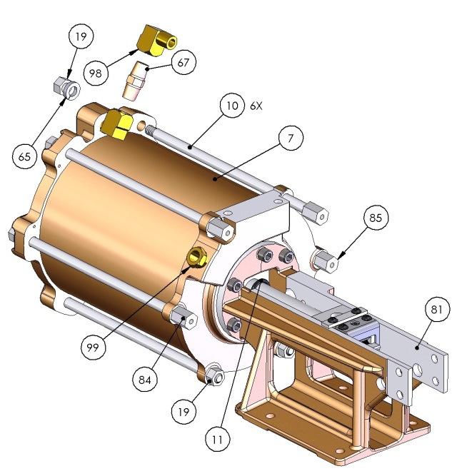
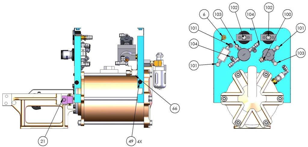
11 Replacement Service Parts Identification Production tools will experience wear of specific parts. Preventative Maintenance, including regular cleaning, lubrication and checking all fasteners for tension will reduce the replacement frequency of these parts. Air Connections for Supply to Cut-off Cylinder Cut-off Cylinder Air Pressure Gauges (2) Quick Disconnect Pin End-of- Stroke Indicator C P Head Air Pressure Regulators (2) Clamp Tension Speed Control Quick Disconnect Pin Cutter Blade, Cutter knife and Gripper Assembly Tension Cylinder Limit Switch Caution! Do not disable Serial Number Location
12 Replacement Service Parts Identification ITEM PART NO. QTY DESCRIPTION ITEM PART NO. QTY DESCRIPTION 1 A SCREW, CAP, 5/16-18 X 1.50 L 59 S OIL, DTE 24 HYDRAULIC (QT) 2 A TUBE, POLYURETHANE, 1/4 (FT) 60 S OIL AND BOTTLE, LUBRICATING 3 C LOCKING COMPOUND, HIGH STRENGTH, RED (CC) 61 S SCREW, CAP, 1/4-20 X 1.75 L 4 G SWIVEL UNION, M X F 62 S NUT, HEX, 1/ G NUT, HEX, 5/ S WASHER, FLAT,.341 ID X.690 OD 6 I FITTING, SWIVEL, 1/8 BARB 64 S WASHER, FLAT,.19 X.44 X.05 7 J TUBE, CYLINDER 65 S LOCK WASHER, 3/8 ID 8 J PIN, SPRING,.125D X 1.35L 66 s ELBOW, MALE R.A, 1/4 NPT X 3/8 TUBE 9 J PLATE, ROD GUIDE 67 S COUPLER, MALE, 1/4 NPT 10 J CYLINDER BOLT 68 S TEE, STREET 11 J O-RING,.734 ID X S DECAL, DTE 24 REQUIREMENT 12 J O-RING, ID X S SEALANT, GASKET AND JOINT (OZ) 13 J SCREW, SET, #10-32 X.188 L 71 S PLUG, CAP, 1/4 NPT 14 J SCREW, SET, 5/16-24 X.375 L 72 S PANEL, FRONT, 15 J PIN, GRIPPER BACK-UP 73 S PISTON, CYLINDER 16 J LOCK WASHER, 5/16 ID 74 S SPACER,.205 X J GASKET, CYLINDER 75 S BOLT, HEX, 1/2-13 X 2.5L 18 J SCREW, CAP, 1/4-28 X.50 L 76 S PLATE, BAND GRIPPER 19 J NUT, HEX, 3/ S GRIPPER, BAND, FINISHED, REX 20 J SCREW, CAP, #8-32 X.38 L 78 S ROD, CYLINDER, 21 J SCREW, CAP, 5/16-18 X.88 L 79 S O-RING,.487 ID X M HEAD, CP, AUTOMATIC 80 S WASHER, 17/32 X 1-1/16 23 M DETENT PIN, QUICK RELEASE 81 S TOOL BASE, 24 M PIN, DETENT. 5/16 D X 2.5 L 82 S PANEL, REAR 25 M DECAL, FRONT, 83 S PANEL, TOP COVER 26 M BRACKET, BASE, 84 S HEX, #10-32 X 3/8-24 X 3/4" L 27 M DOVETAIL, 85 S HEX, #10-32 X 3/8-24 X 5/8" L 28 M CLEVIS, CUTOFF, 86 S ADAPTER, BULKHEAD 29 M LEAF SPRING, 87 S GUARD, FOOT VALVE 30 M PIVOT, CYLINDER, 88 S BASE, INCLINED 31 M BRACKET, SIDE, 89 S VALVE, FLOW CONTROL 32 M CYLINDER, CUTOFF, 90 S VALVE, 4-WAY, ASSY 33 M SPEED CONTROL, MUFFLER, 91 S VALVE, FOOT 34 M DECAL, SERIAL, 92 S REGULATOR, PULL UP 35 M DECAL, SIDE, 93 S REGULATOR, HOLDING 36 M COVER, SHIPPING BOX, 94 S GAUGE, PRESS, 0-100, 1/8 NPT 37 M TUBE, SHIPPING BOX, 95 S GAUGE, HOLDING 38 M BASE, SHIPPING, 96 S COVER, CYLINDER, REAR 39 M VALVE, STROKE LIMIT 97 S NUT, HEX, 3/ M ACTUATOR, BALL, STROKE LIMIT 98 S ELBOW, 90 DEG, STREET 41 M INDICATOR, STROKE LIMIT 99 S BUSHING, REDUCER 42 M PLATE, VALVE, STROKE LIMIT 100 S FITTING, Q-R, STRAIGHT, 1/4 X 1/4NPT 43 M PISTON STOP, 101 S ELBOW, MALE, 90 DEG 44 M DECAL, WARNING 102 S CONNECTOR, 1/8 NPTF X 1/4 OD TUBE 45 M FRONT PLATE, PISTON 103 S ELBOW, MALE, 90 DEG 46 P LABEL, BLANK, 3.5 X S RUN TEE, MALE 47 P BAG, CLEAR PLASTIC 105 S CLAMP, HOSE 48 R TUBING, NYLON, 1/4 (FT) 106 S VALVE, QUICK EXHAUST 49 R BUMPER, SELF ADHESIVE 107 S RING, PANEL MOUNT 50 S SCREW, CAP, 5/16-18 X.63 L 108 S LUBRICATOR 51 S MUFFLER, AIR EXHAUST, 1/4 NPT 109 S GROMMET, HOSE 52 S PLUG, NYLON, 1/4 110 S HOSE ASSY. S S PIN, GRIPPER PIVOT 111 S FILTER 54 S HEAD, FRONT, CYLINDER 112 S SPRING, GRIPPER CLOSING 55 S SEAL COMPOUND, TEFLON (CC) 113 S TEE, UNION, 1/4 56 S LUBRICANT, MOLY PASTE (OZ) 114 S SCREW, BUTTON HD, #10-32 X 3/8 57 S WASHER, LOCK, 1/4 115 SM INSTRUCTIONS, 58 S LETTER, ADHESIVE (EACH) 116 T MUFFLER, EXHAUST


13 Replacement Service Parts Identification


14 Replacement Service Parts Identification


15 Replacement Service Parts Identification

16 Replacement Service Parts Identification
17 Air Connection Diagram Internal tubes are made of bulk part numbers. See chart below. When ordering individual replacement tubes, specify tool part number (), tube part number, tube I.D. letter and tube length. LENGTH (INCHES) TYPE A 3/8 NYLON B N/A 3/8 NYLON C 1/4 NYLON D 8 1/4 NYLON E 7.5 1/4 POLYURETHANE F 6.5 1/4 POLYURETHANE G 9 1/4 POLYURETHANE H 6.5 1/4 POLYURETHANE I 8 1/4 NYLON J 2 1/4 POLYURETHANE K 6 1/4 POLYURETHANE L 8.5 1/4 NYLON M 15 1/4 NYLON N 13 1/4 POLYURETHANE O 10 1/4 POLYURETHANE P 36 1/4 POLYURETHANE Q 30 1/4 POLYURETHANE R 3 1/4 POLYURETHANE S 13 1/4 POLYURETHANE T 8 1/4 POLYURETHANE U 2 1/4 POLYURETHANE
18 Factory Services Additional Factory Support and Service: Factory Service is Available Users of the should have years of dependable production if the preventative maintenance procedures are followed as outlined in this manual. In addition to available service parts, BAND-IT has additional factory service available. Service charges in addition to parts replacement charges will be invoiced if tool is not covered by our warranty. Please visit our website for our warranty information. /Warranty.html Service Information 1. If applicable, test and inspect tool to determine source of problem. 2. Totally dismantle tool and clean all parts. 3. Refinish external parts such as castings, cylinder, etc. 4. Inspect all parts for wear and damage. Replace as needed*. 5. Replace all expendable parts* such as gaskets, O-rings. 6. Reassemble, adjust, test, and inspect. 7. Clean exterior of tool. *Parts replaced are invoiced at current parts prices
GRSM17 Pneumatic Center Punch Tool Owner s Manual and Operating Instructions
 Owner s Manual and Operating Instructions Table of Contents Page Information 2 Safety Guidelines and Warranty 3 Overview and Installation 4 Air System Requirements 5 Setting Controls 6 Installing Clamps
S75099 Pneumatic Junior Clamp Application Tool Owner s Manual and Tool Operating Instructions
 Owner s Manual and Tool Operating Instructions P: 1-800-525-0758 F: 1-800-624-3925 1 Table of Contents Page Information 2 Table of Contents 3 Safety Guidelines and Warranty 4 Tool Performance and Overview
OPERATION AND MAINTENANCE MANUAL
 WREN IBT SERIES HYDRAULIC TORQUE WRENCHES IBT SQUARE DRIVE SERIES OPERATION AND MAINTENANCE MANUAL FOR WREN Products: POINT 75, 1IBT, 3IBT, 5IBT, 8IBT, 10IBT, 20IBT, 25IBT, 35IBT, 50IBT SQUARE DRIVE HYDRAULIC
AIR/HYDRAULIC INJECTION GUN MODEL INSTRUCTIONS
 I. OPERATION & DESCRIPTION The Air / Hydraulic Injection Gun is a high-pressure tool that should be used with caution and according to these instructions. IMPORTANT: The Gun is 0,000 psi rated. Do not
Operation and Maintenance Manual for BS and BH Hydraulic Torque Wrenches
 BOLTORQ Operation and Maintenance Manual for BS and BH Hydraulic Torque Wrenches It is operating manual of BS series and BH series wrenches, please read carefully and follow the instructions. Warning and
69-74 VW Beetle IRS Rear Kit Part No
 www.airliftcompany.com 69-74 VW Beetle IRS Rear Kit Part No. 75615 MN-476 (01102) ECN 3455 Please read these instructions completely before proceeding with installation A C B E D AA F F ITEM QTY. PART
Operating Manual & Safety Instructions ProTorc Hydraulic Torque Wrench Model # PTLC - Please read in full before operating ProTorc Torque Wrench -
 Operating Manual & Safety Instructions ProTorc Hydraulic Torque Wrench Model # PTLC - Please read in full before operating ProTorc Torque Wrench - ProTorc Important Safety Instructions READ ALL INSTRUCTIONS
Robo-Assist Accessory
 Robo-Assist Accessory Kit 85607617 For use with BaseLine by COATS Tire Changers This is a supplement to your operating manual and covers the installation and use of the Robo-Assist accessory. If you do
82-01 Chevy S-10/ GMC Sonoma Front Kit Part No B
 www.airliftcompany.com 82-01 Chevy S-10/ GMC Sonoma Front Kit Part No. 75512B MN-481 (02105) ECN 3549 Please read these instructions completely before proceeding with installation Left Side Upper Shock
Air / Hydraulic Pump
 Form No. 538016 Parts List & Operating Instructions for: 2510A Original Instructions Air / Hydraulic Pump Maximum Capacity: 690 bar (10,000 psi) Description: The 2510A air/hydraulic pump is designed to
4050A. Tire Changer. Parts Identification. For servicing single piece automotive and most light truck tire/wheel assemblies
 4050A Tire Changer For servicing single piece automotive and most light truck tire/wheel assemblies Parts Identification READ these instructions before placing unit in service KEEP these and other materials
Instruction Manual. Maximum Operating Pressure 700 bar
 Remote Hydraulic Cutter Model HC-120R Maximum Operating Pressure 700 bar ABSOLUTE EQUIPMENT PTY LTD 2/186 Granite Street, GEEBUNG QLD 4034 Australia sales@absoluteequipment.com.au Phone: +61 7 3865 4006
VALVE AND PLUMBING KIT INSTRUCTIONS SMC 84Q & 2408 LOADERS NEW HOLLAND TRACTORS MODEL 2WD 4WD LESS CAB WITH CAB 1720 X X X 1920 X X X
 ASSEMBLY MANUAL Keep With Operator s Manual VALVE AND PLUMBING KIT INSTRUCTIONS SMC 84Q & 2408 LOADERS NEW HOLLAND TRACTORS MODEL 2WD 4WD LESS CAB WITH CAB 1720 X X X 1920 X X X TRACTOR AND VALVE KIT GENERAL
HexPro Series Low Profile Wrenches
 HexPro Series Low Profile Wrenches Operation and Maintenance Manual Model 2HP 4HP 8HP 14HP 30HP www.torquetoolsinc.com Use the HEXPRO Series Low Profile Wrenches Model 2HP 4HP 8HP 14HP 30HP to install
RUFNEX Series Low Profile Wrenches Operation and Maintenance Manual
 RUFNEX Series Low Profile Wrenches Operation and Maintenance Manual http://www.torsionx.com Use the RUFNEX Series Ultra-Low Profile Wrenches to install and remove large bolts that have minimal wrench clearance.
EURO BEAD BREAKER MODEL # Instruction Manual Parts Breakdown
 EURO BEAD BREAKER MODEL #10107 Instruction Manual Parts Breakdown Operation WARNING The optional air/hydraulic pump is capable of generating fluid pressure up to 10,000 PSI. Keep both hands on the handles
SAFETY SAFETY CABLE INSTALLATION /00 1 of 6
 SAFETY DO NOT INSTALL, OPERATE OR USE THIS EQUIPMENT UNTIL THE FOLLOWING OPERATING AND SAFETY INSTRUCTIONS HAVE BEEN READ AND UNDERSTOOD. This symbol is used to bring attention to safety precautions and
VALVE AND PLUMBING KIT NEW HOLLAND 7310 LOADER NEW HOLLAND TRACTORS
 ASSEMBLY MANUAL Keep With Operator s Manual VALVE AND PLUMBING KIT NEW HOLLAND 73 LOADER NEW HOLLAND TRACTORS MODEL 2WD FWA LESS CAB WITH CAB TT55 X X X TT75 X X X Valve and plumbing kit can be installed
VALVE AND PLUMBING KIT 2408TL LOADER AGCO & MASSEY FERGUSON TRACTORS
 ASSEMBLY MANUAL Keep With Operator s Manual VALVE AND PLUMBING KIT 2408TL LOADER AGCO & MASSEY FERGUSON TRACTORS AGCO MASSEY FERGUSON CAB ROPS ST34A 1533 X ST41A 1540 N/A X TRACTOR AND VALVE KIT GENERAL
AUTO REWIND AIR HOSE REEL
 Model #s 46845, 46848 AUTO REWIND AIR HOSE REEL OPERATOR S MANUAL STORE THIS MANUAL IN A SAFE PLACE FOR FUTURE REFERENCE!? NEED HELP? Save time, contact us first. 888-648-8665 support@tekton.com WARNING:
Under Axle Jack Max. Capacity: 25 Tons
 SPX Corporation 655 Eisenhower Drive Owatonna, MN 55060-0995 USA Phone: (507) 455-7000 Tech. Serv.: (800) 533-6127 Fax: (800) 955-8329 Order Entry: (800) 533-6127 Fax: (800) 283-8665 International Sales:
Operating, Servicing, and Safety Manual Model # Hydraulic Bender
 Operating, Servicing, and Safety Manual Model # 900 90 Hydraulic Bender CAUTION: Read and Understand These Operating, Servicing, and Safety Instructions, Before Using This Machine. 1-800-467-2464 10 Cooperative
Low Profile Wrenches Operation and Maintenance Manual
 Low Profile Wrenches Operation and Maintenance Manual http://www.torquetoolsinc.com Use the HEXPRO Series Low Profile Wrenches Model 2HP 4HP 8HP 14HP 30HP to install and remove large bolts that have minimal
 Operation and Maintenance Manual http://www.torsionx.eu Use the MaxDrv Series Square Drive Torque Wrench Model.75, 1, 3, 5, 8, 10, 20, 25, 35, 50 to install and remove threaded fasteners requiring precise
OPERATING INSTRUCTIONS & SERVICE MANUAL BLUE MAX II HYDROSTATIC TEST PUMP
 PAGE 1 OF 10 OPERATING INSTRUCTIONS & SERVICE MANUAL BLUE MAX II HYDROSTATIC TEST PUMP EFFICIENT, EASY OPERATION Air operated pump Wide range of pressures and volumes Easy to operate controls Output pressure
Convertible - Rated 3 4-Ton /2-Ton Nylon Strap Hoists Refer to any questions about the use, application, repair or testing of this hoist to:
 Operating and Servicing Instructions for Convertible - Rated 3 4-Ton - 1 1 /2-Ton Nylon Strap Hoists Refer to any questions about the use, application, repair or testing of this hoist to: Hubbell / Chance
Tooling Assistance Center
 Safeguards are designed into this application equipment to protect operators and maintenance personnel from most hazards during equipment operation. However, certain safety precautions must be taken by
3.1 DISPENSER BLACK SHADOW SERIES. Tools Needed for Mounting SCS Dispenser Hammer
 SCS 2 BLACK SHADOW SERIES 3.1 DISPENSER ALWAYS OBSERVE PRODUCT SAFETY AND HANDLING INSTRUCTIONS. ALWAYS DIRECT DISCHARGE AWAY FROM YOU or other persons. ALWAYS DISPENSE CLEANERS AND CHEMICALS AS DIRECTED
Hydraulics. Part B, Section 1. This section covers the following unit configurations. 3700V 3800V 3900V
 Part B, Section 1 Model Voltage Pump Manifold Control This section covers the following unit configurations. 3500V 3700V 3800V 3900V All Piston (F) 4-Port (A) 6-Port (B or C) -Port (S or T) Vista Standard
 Operation and Maintenance Manual Model.75,, 3, 5, 8, 0, 0, 5, 35, 50 http://www.torsionx.com Use the MaxDrv Series Square Drive Torque Wrench Model.75,, 3, 5, 8, 0, 0, 5, 35, 50 to install and remove threaded
IBT Series Square Drive Torque Wrenches
 IBT Series Square Drive Torque Wrenches Operation and Maintenance Manual Model.75, 1, 3, 5, 8, 10, 20, 25, 35, 50 http://www.torsionx.com Use the IBT Series Square Drive Torque Wrenches Model.75, 1, 3,
1 Green Pressure Regulator Spring Automatic transmissions operate at temperatures between 150ºF and
 Installation Instructions for 603107 Valve Body Kit C-4 1970 & Later Tools Required Speed Handle or Ratchet 3/8 Drive 1/2 Socket 3/8 Drive 7/16 Socket 3/8 Drive 5/16 Socket 3/8 Drive Small Screwdriver
ACCLAIM OPERATOR, PARTS, AND INSTALLATION MANUAL BX4330 ACCLAIM
 ACCLAIM OPERATOR, PARTS, AND INSTALLATION MANUAL BX4330 ACCLAIM Tow Bar Class III (5000 lb) 2 Inch Coupler TOWING PRODUCTS DIVISION Page 1 of 8 292-2205 4/23/09 SAFETY DO NOT INSTALL, OPERATE OR USE THIS
Frame. Axle. Kit No Please read these instructions completely before proceeding with installation. Figure 1. Kit Parts List FORWARD B J
 Kit No. 70 Please read these instructions completely before proceeding with installation by www.airliftcompany.com MN-7 (008) ECN 08 Item P/N Description Qty. A B C D E F H I 807 0770 0006 88 70 87 8 8
Polypropylene Piston Drum Pumps
 Please read and save this Repair Parts Manual. Read this manual and the General Operating Instructions carefully before attempting to assemble, install, operate or maintain the product described. Protect
ASSEMBLY MANUAL. Keep With Operator s Manual
 ASSEMBLY MANUAL Keep With Operator s Manual 2-6347 VALVE AND PLUMBING KIT INSTRUCTIONS SMC 64Q LOADER KUBOTA TRACTORS MODEL 2WD 4WD LESS CAB WITH CAB B2150DT & B2150HSD X X B8200DT & B8200HSD X X B9200DT
Kit No Please read these instructions completely before proceeding with installation. Air Spring Kit Parts List. Bracket Attaching Hardware
 Kit No. 59532 MN-572 (021108) ECR 7136 Please read these instructions completely before proceeding with installation Air Spring Kit Parts List A Item Description Quantity A Air Sleeves 2 B Upper Brackets
INSTALLATION INSTRUCTIONS
 INSTALLATION INSTRUCTIONS Part # 751-FP2500 IMPORTANT INFORMATION This Jagg oil cooler must be installed following these instructions. Read the easy-to-follow instructions fully prior to starting the installation
TS1251 PRESSURE DISPENSER USER'S MANUAL
 TS1251 PRESSURE DISPENSER USER'S MANUAL TABLE OF CONTENTS SECTION DESCRIPTION PAGE NUMBER 1.0 CAUTIONS AND WARNINGS... 3 2.0 INTRODUCTION... 4 3.0 DESCRIPTION... 4 & 5 4.0 SET UP AND INSTALLATION... 6
I. Assembling the Air Spring
 B F H G D FRONT I Assembling the Air Spring 1 Install 90 degree air swivel fitting (D) to the top of the bellow This fitting is precoated with sealant Using an open-end wrench, tighten 1 and 1 /2 turns
Please read these instructions completely before proceeding with installation. Read all maintenance guidelines on page 7 before operating the vehicle.
 MN-643 (02511) ECR 5461 Kit No. 39205 Please read these instructions completely before proceeding with installation Item P/N Description Quantity A 26391 Driver-Side Beam Assembly 1 B 26414 Passenger-Side
Safety, Operation and Maintenance Instructions For Long & Short Nose Upholstery Air Stapler (NS10 & NS11)
") Safety, Operation and Maintenance Instructions For Long & Short Nose Upholstery Air Stapler (NS10 & NS11) Important: Drop 3 drops of oil into the stapler air inlet BEFORE first use. See page 2. Please
Safety, Operation and Maintenance Instructions For Long & Short Nose Upholstery Air Stapler (NS10 & NS11) Important: Drop 3 drops of oil into the stapler air inlet BEFORE first use. See page 2. Please
VLW18TE, VLW18TI HYDRAULIC VERTICAL LIFTING WEDGES. Operator Instruction Manual INNOVATION IN ITS MOST FUNCTIONAL FORM
 VLW18TE, VLW18TI HYDRAULIC VERTICAL LIFTING WEDGES Operator Instruction Manual info@equalizerinternational.com www.equalizerinternational.com INNOVATION IN ITS MOST FUNCTIONAL FORM INDEX SECTION CONTENTS
Maintenance Information
 80234313 Edition 1 June 2006 Air Grinder, Die Grinder, Sander and Belt Sander Series G1 (Angle) Maintenance Information Save These Instructions WARNING Always wear eye protection when operating or performing
THIS PRODUCT IS FOR PROFESSIONAL LABORATORY USE ONLY USER'S MANUAL. WELLS ENGINE UNIT 230 VOLT Product No. U905, U906, U907, U908
 DENTAL, INC. TECHNICAL BULLETIN U807-022510 5860 FLYNN CREEK ROAD READ ALL INSTRUCTIONS P.O. BOX 106 BEFORE PROCEEDING COMPTCHE, CALIFORNIA, U.S.A. 95427 SAVE THIS FOR FUTURE REFERENCE THIS PRODUCT IS
MicroCoat. System Operating Manual MC2000 Series. MC785, MC785-WF Spray Valves. US: UK: Mexico:
 MicroCoat System Operating Manual MC2 Series MC785, MC785-WF Spray Valves A NORDSON COMPANY US: 8-498-8865 UK: 8 585733 Mexico: 1-8-556-3484 Introduction The MicroCoat System provides precise lubrication
AIR DRIVEN TUBE CLEANER
 MODEL PGX-2 AIR DRIVEN TUBE CLEANER OPERATING INSTRUCTIONS & SERVICE MANUAL Rev: A, 5/11/2007 TO REDUCE THE RISK OF INJURY AND EQUIPMENT DAMAGE USER MUST READ AND UNDERSTAND OPERATOR S MANUAL. Thomas C.
Maintenance Information
 80234313 Edition 2 May 2014 Air Grinder, Die Grinder, Sander and Belt Sander Series G1 (Angle) Maintenance Information Save These Instructions Product Safety Information WARNING Failure to observe the
Maintenance and Repair
 Maintenance and Repair WARNING ALWAYS shut off the engine, remove key from ignition, make sure the engine is cool, and disconnect the spark plug and positive battery terminal from the battery before cleaning,
HYDRAULIC TUBE CUTTER
 7, OD 7, -/ OD 7, OD HYDRAULIC TUBE CUTTER OPERATING INSTRUCTIONS & SERVICE MANUAL Rev: A, //007 TO REDUCE THE RISK OF INJURY AND EQUIPMENT DAMAGE USER MUST READ AND UNDERSTAND OPERATOR S MANUAL. Thomas
INSTALLATION INSTRUCTIONS
 28 INSTALLATION INSTRUCTIONS SECTION - AIR SPRING SECTION 2 - AIR ACCESSORY 2-5 ! IMPORTANT PLEASE DON T HURT YOURSELF, YOUR KIT OR YOUR VEHICLE. TAKE A MINUTE TO READ THIS IMPORTANT INFORMATION. This
Service Jacks. Operating Instructions & Parts Manual. Model Number. Capacity 4 Ton 4 Ton Air/ Manual 10 Ton 10 Ton Air/ Manual HW93657/ HW93660
 Service Jacks Operating Instructions & Parts Manual Model Number HW93657 HW93667 HW93660 HW93662 Capacity 4 Ton 4 Ton Air/ Manual 10 Ton 10 Ton Air/ Manual Made in North America HW93657/ HW93660 HW93667/
OPERATION AND PARTS MANUAL
 OPERATION AND PARTS MANUAL MODEL NUMBER : PART NUMBER : GTL 1110 1900-0510 SERIAL NUMBER : BAYNE MACHINE WORKS, INC. PHONE: (864) 288-3877 910 FORK SHOALS ROAD TOLL FREE: (800) 535-2671 GREENVILLE S.C.,
WARNING NOTICE CAUTION ASSEMBLY INSTRUCTIONS
 MODEL 284 EZ-GLIDE SYSTEM 10' HIGH CUBE VAN DRIVER SIDE ALUMINUM DROP DOWN LADDER RACK ATTENTION Read and understand all instructions and warnings before operating or using this product. WARNING This product
SLM - Sealing Liquid Monitor INSTRUCTIONS FOR USE
 INSTRUCTIONS FOR USE 1/8 1 INSTALLATION SLM - Sealing Liquid Monitor INSTRUCTIONS FOR USE 1.1 Mounting The SLM has a mounting plate for simple installation. The SML can be mounted using a bolt already
Tools Needed for Mounting Cleá Filling Station
 ALWAYS OBSERVE PRODUCT SAFETY AND HANDLING INSTRUCTIONS. ALWAYS DIRECT DISCHARGE AWAY FROM YOU or other persons. ALWAYS DISPENSE CLEANERS AND CHEMICALS AS DIRECTED ON THE LABEL. ALWAYS DISPENSE INTO APPROVED
Temperature Sensor Series
 GENERAL DESCRIPTION The patented* No. 85026-Series Temperature Sensor contains a two-position valve operated by temperature variations around the integral sensing bulb. It is used to vent or block a pneumatic
Maintenance Information
 16572679 Edition 2 May 2014 Air Drill QP Series Maintenance Information Save These Instructions Product Safety Information WARNING Failure to observe the following warnings, and to avoid these potentially
GBP784B INSTALLATION TOOL
 GBP784B INSTALLATION TOOL GAGE BILT MADE IN U.S.A. GAGE BILT PRODUCTS CORP. 14500 Barber Drive (586) 771-7664 Warren, Mi 48088 (586) 771-2665 Fax e-mail:solutions@gagebilt.com / www.gagebilt.com TABLE
INSTRUCTIONS AND PARTS LIST FOR MODEL 70H & 75H HAND-OPERATED HYDRAULIC PRESS
 INSTRUCTIONS AND PARTS LIST FOR MODEL 70H & 75H HAND-OPERATED HYDRAULIC PRESS SETTING UP THE PRESS FOR OPERATION For shipping convenience, the gauge, pump handle, hoist crank, screw nose and base angles
ASSEMBLY MANUAL SMC 2491 LOADER VALVE AND PLUMBING KIT INSTRUCTIONS KUBOTA TRACTORS
 ASSEMBLY MANUAL Keep With Loader Operator's Manual SMC 2491 LOADER VALVE AND PLUMBING KIT INSTRUCTIONS KUBOTA TRACTORS MODEL 2WD 4WD LESS CAB WITH CAB L5450 X X Valve and plumbing kit can be installed
WCI-20 Power-Pak Coldwork Hydraulic Power Supply Rev B
 WCI-20 Power-Pak Coldwork Hydraulic Power Supply Rev B OM-PS-9303-2 Seattle, Washington WCI-20 Power Pak Manual Table of Contents Section 1 Introduction 1.1 Introduction... 1 1.2 Safety Precautions...
Return to Instruction Sheet index. Installation Instructions For C-4 70 and Later, Except 70 Falcon
 Page 1 of 8 Return to Instruction Sheet index TCI 260100 Trans-Scat Automatic Transmission Installation Instructions For C-4 70 and Later, Except 70 Falcon TCI 260100 Kit Contains: Qty. Description One
VALVE AND PLUMBING KIT 2409 LOADER CUB CADET & KIOTI TRACTORS
 ASSEMBLY MANUAL Keep With Operator s Manual VALVE AND PLUMBING KIT 2409 LOADER CUB CADET & KIOTI TRACTORS TRACTOR MODELS CUB CADET 8404, 8454 KIOTI DK45, DK50 ROPS X X TRACTOR AND VALVE KIT GENERAL INFORMATION
TWO-STAGE HYDRAULIC PUMP. RWP55-IBT-Air
 ORIGINAL INSTRUCTIONS Form No.1000458 5 SPX Corporation 5885 11th Street Rockford, IL 61109-3699 USA Tech. Services: (800) 477-8326 Fax: (800) 765-8326 Order Entry: (800) 541-1418 Fax: (800) 288-7031 Internet
High Lift Transmission Jack
 655 Eisenhower Drive Owatonna, MN 55060 USA Phone: (507) 455-7000 Tech. Serv.: (800) 533-6127 Fax: (800) 955-8329 Order Entry: (800) 533-6127 Fax: (800) 283-8665 International Sales: (507) 455-7223 Fax:
Maintenance Instructions
 General Note These instructions contain information common to more than one model of Bevel Gear Drive. To simplify reading, similar models have been grouped as follows: GROUP 1 Models 11, 0, 1,, (illustrated),,
40041 Heavy Duty ADA System with Booster Bracket for JK Heavy Duty ADA System with Booster Bracket for 2012 to Current JK
 40041 Heavy Duty ADA System with Booster Bracket for 2007-2011 JK 40044 Heavy Duty ADA System with Booster Bracket for 2012 to Current JK 40049 Heavy Duty ADA System Universal for all vehicles (booster
The portable, hand-held rebar bending and cutting system. OPERATOR S MANUAL Made in U.S.A.
 The portable, hand-held rebar bending and cutting system. OPERATOR S MANUAL -800-665-7549 Made in U.S.A. Thank you for purchasing an EZE BEND SYSTEM. The OPERATOR S MANUAL provides information for all
Maintenance Information
 51984144 Edition 6 May 2014 Air Paving Breaker MX60 & MX90 Maintenance Information Save These Instructions Product Safety Information WARNING Failure to observe the following warnings, and to avoid these
OPERATION AND PARTS MANUAL
 OPERATION AND PARTS MANUAL MODEL NUMBER : PART NUMBER : GRL 1110 1900-0540 SERIAL NUMBER : BAYNE MACHINE WORKS, INC. PHONE: 864.288.3877 910 FORK SHOALS ROAD TOLL FREE: 800.535.2671 GREENVILLE SC, 29605
Installation Instructions
 Instructions Created by an: Suzuki Samurai Replacement Clutch (SKU# STM-CC) Installation Instructions CAUTION: Safety glasses should be worn at all times when working with vehicles and related tools and
FaceClipper Model # Serial #
 FaceClipper 000 Model # Serial # Vertex Fasteners A Subsidiary of Leggett & Platt, Inc. 7 Jarvis Avenue Skokie, Illinois 60076 U.S.A. (87) 9-80 Table of Contents OF EQUIPMENT... OPERATING INSTRUCTIONS...
Heavy Duty Miniature Quick-Change Applicator (Side-Feed Type) with Mechanical or Air Feed Systems
 with Mechanical or Air Feed Systems") Heavy Duty Miniature Quick-Change Applicator (Side-Feed Type) with Mechanical or Air Feed Systems Instruction Sheet 408-8040 30 NOV 17 Rev H Ram Assembly Ram Post Locking Screw Stock Drag Drag Release
Heavy Duty Miniature Quick-Change Applicator (Side-Feed Type) with Mechanical or Air Feed Systems Instruction Sheet 408-8040 30 NOV 17 Rev H Ram Assembly Ram Post Locking Screw Stock Drag Drag Release
Installation Instructions
 CADET Centerset Lavatory Faucet with Speed Connect Drain Installation Instructions Congratulations on purchasing your American Standard faucet with the Speed Connect Drain, a feature found only on American
Air / Hydraulic Pump Instructions. CAUTION: Read and Understand These Operating, Servicing, and Safety Instructions, Before Using This Machine.
 Air / Hydraulic Pump Instructions CAUTION: Read and Understand These Operating, Servicing, and Safety Instructions, Before Using This Machine. 1-800-467-2464 10 Cooperative Way Wright City, MO 63390 P.O.
AIR/HYDRAULIC LIFT TABLE CART 770-LB.
 AIR/HYDRAULIC LIFT TABLE CART 770-LB. OWNER S MANUAL WARNING: Read carefully and understand all MACHINE ADJUSTMENT AND OPERATION INSTRUCTIONS before operating. Failure to follow the safety rules and other
Wheeler Mfg. Div Rex Intl USA Inc Jefferson Road Ashtabula, OH Tel: Fax:
 Wheeler Mfg. Div Rex Intl USA Inc. 3744 Jefferson Road Ashtabula, OH 44004 Tel: 800-321-7950 Fax: 440-992-2925 wheeler@wheelerrex.com www.wheelerrex.com Some Operating Hints...... 2 The 68115 features
 9000 LB Rolling Air Jack Installation, Operation and Repair Parts Information NOTICE - AIR SUPPLY MUST HAVE IN-LINE FILTER/REGULATOR/LUBRICATOR (NOT INCLUDED) TO VALIDATE THE ROLLING AIR JACK WARRANTY
Air Actuated Hydraulic Bottle Jacks
 Air Actuated Hydraulic Bottle Jacks Operating Instructions & Parts Manual Model Number Atd-7412 Atd-7420 Capacity 12 Ton 20 Ton Atd Tools Inc. 160 Enterprise Drive, Wentzville MO 63385 Printed in China
INSTRUCTIONS DURA SHOT S SPRAYERS DIRECTIONS FOR OPERATING DURA SHOT S. 24 oz. DURA SURE SHOT S SPRAYER.
 DURA SHOT S SPRAYERS INSTRUCTIONS Refillable, reusable. Extra versatile. Pressurized by free air DURA SHOT S 24 oz. DIRECTIONS FOR OPERATING DURA SHOT S SPRAYERS 1) ALWAYS DEPRESSURIZE SPRAYER BEFORE REMOVING
Table of Contents. Safety symbols... 3 Assembly 6. Operation Maintenance Troubleshooting 11. Storage. 12. Notes. 13
 Table of Contents Safety symbols... 3 Assembly 6 Operation... 8 Maintenance... 10 Troubleshooting 11 Storage. 12 Notes. 13 2 Safety Information Attention; this machine can be dangerous! All operators should
Start Up & Troubleshooting Manual. Resfab Equipment Inc. St Jean Sur Richelieu Website: resfab.com
 Start Up & Troubleshooting Manual Resfab Equipment Inc. 725 Rossiter St Jean Sur Richelieu 1 450 359 0800 Website: resfab.com Yogurt Blender Service Manual Page SECTION 1: Start Up and Repair... 3 thru
Sachs shock manual. ( ) 2 & 4 Stroke RR Enduro. ( ) RS Dual Sport
 2 & 4 Stroke RR Enduro. ( ) RS Dual Sport") Sachs shock manual (2013 2015) 2 & 4 Stroke RR Enduro (2014-2015) RS Dual Sport 1 Introduction The procedures in this manual must take place in a clean environment using professional tools and some specific,
Sachs shock manual (2013 2015) 2 & 4 Stroke RR Enduro (2014-2015) RS Dual Sport 1 Introduction The procedures in this manual must take place in a clean environment using professional tools and some specific,
Page 1 of 19. Part# /10/2006
 Part# 1002733-01 10/10/2006 This manual contains important information concerning the installation and operation of the gun washers listed above. Read manual thoroughly and keep for future reference INSTRUCTIONS
Service Guide. High-Pressure Grease Pump. 100 psi (6.8 bar) High-Pressure Pump Model 7785 Series Specifications
 High-Pressure Pump Model 7785 Series Specifications") Description Service Guide 7785-A5 7785-B5 7785-MA The major components of the pump models in the 7785 series consist of an air-operated motor and a pump tube. The air motor connects directly to the double-acting
Description Service Guide 7785-A5 7785-B5 7785-MA The major components of the pump models in the 7785 series consist of an air-operated motor and a pump tube. The air motor connects directly to the double-acting
Air Assist Bottle Jack Max. Capacity: 12 Tons (4313C) & 20 Tons (4321C) Operating Range: psi
 & 20 Tons (4321C) Operating Range: psi") Form No. 545742 Parts List and Operating Instructions for: 4313C 4321C Air Assist Bottle Jack Max. Capacity: 12 Tons (4313C) & 20 Tons (4321C) Operating Range: 40 150 psi 45 44 43 42 41 40 39 22 1 37 28
Form No. 545742 Parts List and Operating Instructions for: 4313C 4321C Air Assist Bottle Jack Max. Capacity: 12 Tons (4313C) & 20 Tons (4321C) Operating Range: 40 150 psi 45 44 43 42 41 40 39 22 1 37 28
MODEL G300 BRAKE BLEEDER
 MODEL G300 BRAKE BLEEDER Installation, Operation & Repair Parts Information Branick Industries, Inc. 4245 Main Avenue P.O. Box 1937 Fargo, North Dakota 58103 REV120716 P/N: 81-0035H THIS PAGE INTENTIONALLY
High Pressure Abrasive Blast Cabinet 42000
 Please read and save these instructions. Read through this owner s manual carefully before using product. Protect yourself and others by observing all safety information, warnings, and cautions. Failure
JARVIS. Model HTC -80 Hog Toe Cutter
 Model HTC -80 Hog Toe Cutter HTC -80 Standard HTC -80 Pistol Grip EQUIPMENT SELECTION... Ordering No. HTC--80 Standard... 4025061 HTC--80 Pistol Grip... 4025100 HTC--80 Pistol Grip Long... 4025114 without
IMT Bead Breaker 1000
 Manual Part Number 99903638 IMT Bead Breaker 000 Revised 2050423 Copyright 204 Iowa Mold Tooling Co., Inc. All rights reserved IOWA MOLD TOOLING CO., INC. PO Box 89 Garner, IA 50438 Tel: 64-923-37 FAX:
OPERATOR'S MANUAL FOR DOUBLE ACTING PISTON HAND PUMP
 OPERATOR'S MANUAL FOR DOUBLE ACTING PISTON HAND PUMP OPERATION AND SERVICE GUIDE JAN. 00 Refer to Bulletin P-0 and Parts List P-9990. SAFETY PRECAUTIONS. This manual contains important information for
MODEL 25-OM-10-C & 25-OA-10-C HYDRAULIC BOOSTER
 SPX Corporation 5885 11th Street Rockford, IL 61109-3699 USA Internet Address: http://www.powerteam.com Tech. Services: (800) 477-8326 Fax: (800) 765-8326 Order Entry: (800) 541-1418 Fax: (800) 288-7031
Model 210HP Beadbreaker
 00020HP:99900657: 2040409 Model 20HP Beadbreaker PARTS AND SERVICE MANUAL IOWA MOLD TOOLING CO., INC. BOX 89, GARNER, IA 50438-089 TEL: 64-923-37 TECHNICAL SUPPORT FAX: 64-923-2424 MANUAL PART NUMBER 99900657
PERFORM THE FOLLOWING SAFETY CHECK DAILY:
 FITNESS Introduction We at Vectra Fitness appreciate your selection of our product for your fitness program, and invite your questions and comments. We're sure that you ll be pleased with your new Vectra
M-3025CB-AV Fuel Pump
 SAVE THESE INSTRUCTIONS M-3025CB-AV Fuel Pump Owner s Manual TABLE OF CONTENTS General Information... 2 Safety Instructions... 2 Installation... 3 Operation... 4 Maintenance... 4 Repair... 5 Troubleshooting...
ASSEMBLY INSTRUCTIONS / OWNERS MANUAL AIR BIKE AB-1
 AIR BIKE AB- ASSEMBLY INSTRUCTIONS / OWNERS MANUAL IMPORTANT : READ ALL ASSEMBLY INSTRUCTIONS AND SAFETY PRECAUTIONS BEFORE USING THIS PRODUCT. REFERENCE ALL SAFETY GUIDELINES AND WARNING LABELS. RETAIN
MODEL EGA200 OWNERS MANUAL
 3/8 RATCHET WRENCH MODEL EGA200 OWNERS MANUAL www.eaglecompressor.com 1-800-551-2406 READ THE ENTIRE MANUAL BEFORE PUTTING THIS TOOL IN SERVICE Limited Air Tool Warranty Wood Industries, Inc. warrants
OPERATOR, PARTS AND INSTALLATION MANUAL. BX7330 AVENTA TM Tow Bar TOWING PRODUCTS DIVISION
 A V E N T A TM OPERATOR, PARTS AND INSTALLATION MANUAL BX7330 AVENTA TM Tow Bar TOWING PRODUCTS DIVISION SAFETY DO NOT INSTALL, OPERATE OR USE THIS EQUIPMENT UNTIL THE FOLLOWING OPERATING AND SAFETY INSTRUCTIONS
KING CANADA 950W PORTABLE GENERATOR MODEL: KCG-951G INSTRUCTION MANUAL COPYRIGHT 2011 ALL RIGHTS RESERVED BY KING CANADA TOOLS INC.
 KING CANADA 950W PORTABLE GENERATOR MODEL: KCG-951G INSTRUCTION MANUAL COPYRIGHT 2011 ALL RIGHTS RESERVED BY KING CANADA TOOLS INC. WARRANTY & SERVICE INFORMATION 1-YEAR LIMITED WARRANTY FOR THIS 950W