Wheeler Mfg. Div Rex Intl USA Inc Jefferson Road Ashtabula, OH Tel: Fax:
|
|
|
- Fay McDonald
- 6 years ago
- Views:
Transcription

1 Wheeler Mfg. Div Rex Intl USA Inc Jefferson Road Ashtabula, OH Tel: Fax:
2 Some Operating Hints The features a new of type safety control switch. It combines the reversing switch with a trigger type engaging switch in a manner that the operator cannot reverse the direction of rotation without first releasing the trigger switch. The operation of this switch is very simple, to change the direction of rotation of the machine, simply release the trigger switch and then slide the reverse switch to either the forward or reverse position. The machine is then ready for normal operation by depressing the trigger switch. Care in Servicing The power drive is an on the job tool. It is designed for everyday use and for trouble-free operation. The frame is made of high strength cast aluminum alloy. Lubrication The bearings in the motor are of the sealed type and are lubricated. No additional lubricant is required. Gears The gear housings on the power drive are extra large and should normally contain enough grease for the life of the tool. However, should the tool be subjected to severe usage, provision has been made through two grease fittings to supply additional lubricant. One of these is on the gear case cover, just ahead of the motor, which supplies the reduction gears and the other is at the side of the frame for lubricating the worm gear. The grease originally supplied in the tool is a special hi-temperature grease No. 1 consistency, readily obtainable from any of the major oil companies. Care of the Motor The motor brushes should be inspected at least once a year, according to the usage of the machine. Always be sure to see that the brushes are returned to their original side and the position from which they were taken. This can be done by marking the brush with a red pencil before it is removed, to indicate the side from which it is taken. Be sure to keep the motor clear of dust and dirt by cleaning it with an air hose from time to time. Caution Your is designed to give satisfactory service with ordinary treatment. Do not drop as this may cause damage.


3 Other products available to use with the power drive Adapter for 12R Drop Head Dies Square Female Adapter Safety Adapter Assembly Rising Stem Torque Adapter Hydrant Nut Telescoping Valve Keys Quick disconnect pull pins make adjustments fast and easy. Both a manual handle and a 1 square power adapter are included. 2 square female drive fits most standard valves. Available as: Foot Telescoping Valve Key Foot Telescoping Valve Key Foot Extension Extends your 8806 to 8808


4 4
5 Item Part No Description 5 Qty FRAME - POWER DRIVE (MACHINING) GEAR COVER (MACHINING) BEARING CAP GASKET MOTOR PINION PINION SHAFT WORM WEAR RING SPACER BEARING RETAINING RING WOODRUFF KEY NO. 3, USA STD WOODRUFF KEY NO SPUR GEAR INTERMEDIATE GEAR BEARING BEARING LOCK NUT BEARING BEARING LOCK WASHER, W WORM GEAR COVER GASKET WORM GEAR (MACHINING) POWER DRIVE HANDLE EXTENSION CORD SET GREASE FITTING /4-20 x 1/2" STAINLESS STEEL BHCS /4-20 x 5/8" SOCKET HEAD CAP SCREW /4-20 x 1 1/4" SHCS O-RING (BUNA) /4-20 x 1/4" CUP POINT SET SCREW /16 DIA x 1 1/2" ROLL PIN MOTOR 1/2 HP, 115 V GROMMET-RUBBER CORD PROTECTOR /4-20 x 1" SHCS /4-20 THIN ESNA NUT HANDLE & SWITCH KIT x 1 SLOTTED TORX HEAD STEEL RETAINING RING /4-20 x 3/4" SHCS 6
6 Handle Assembly for Power Drive 6 Handle assembly sold complete. No separate parts provided. This drawing is for information only.


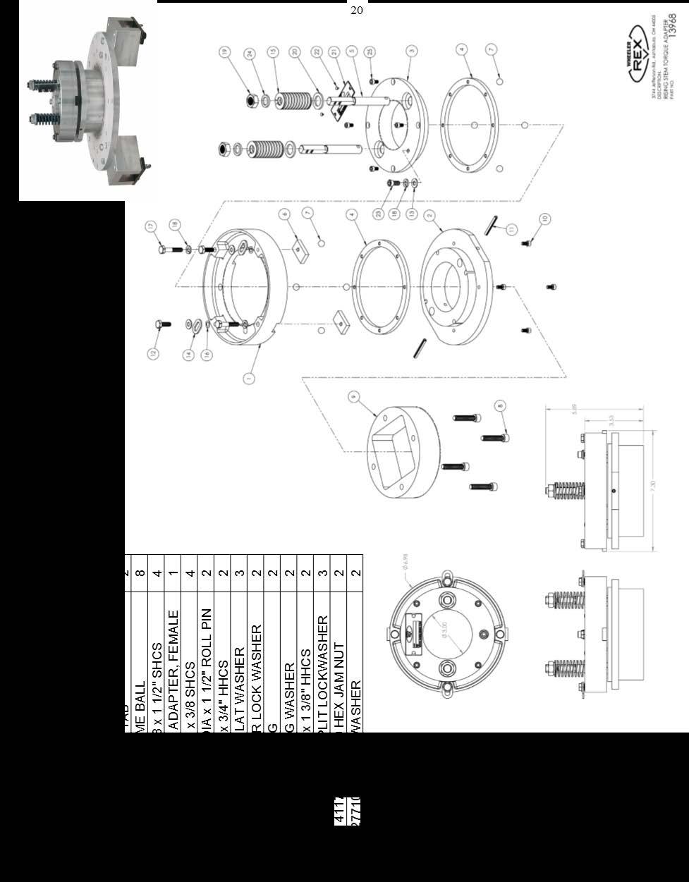
7 7 Item Part No Description Qty ADJUSTING NUT SPRING ADAPTER MACHINED ADAPTER PLATE SQUARE DRIVE PAWL RATCHET DOG /4 WASHER #10-24 x 5/8" SHCS /4-20 x 3/4" HHCS /4-20 x 1 3/8" HHCS FINGER LOCK WASHER #10 SPLIT LOCK WASHER /4" SPLIT LOCK WASHER /16" FLAT WASHER SPRING WASHER COTTERLESS HITCH PIN 1
8 8 Attaching the Safety Adapter Assembly 8 Finger Lock Washers Finger Lock Washers Body Rising Stem Torque Adapter Make sure the finger lock washers are inside of the body Drive tab (one here and one on opposite side There are two (2) drive tabs on the unit. 2 Sets of Slots This is the bottom view of the Power Drive. There are two (2) sets of slots located on the bottom drive gear.
9 9 Attaching the Safety Adapter Assembly continued... 9 Drive Tab - shown properly located in drive gear slots With the power drive & torque adapter upside down, place the torque adapter inside of the power drive. Drive tabs should be properly placed in the drive gear slots of the Power Drive. See Page 14 for proper spacing of counter magnet See Page 28 for proper alignment of counter magnet Flip the Power Drive over with the torque adapter inside of the drive gear. Lock Washers Push the Finger Lock Washers out over the drive gear. This keeps the torque adapter attached to the Power Drive.
 and the counter magnet (located on")

10 10 Attaching the Safety Adapter Assembly continued Check for proper clearance between the Counter (located on the Power Drive) and the counter magnet (located on the torque adapter. There should be 3/16 gap between the counter and the magnet. Stem has engraved graduations of 50 ft lbs increments. Side 1 shown Stem has engraved graduations of 50 ft lbs increments. Side 2 shown Collar Screw - tighten Loosen collar screw with a 3/16 Allen wrench (not provided)
11 Attaching the Safety Adapter Assembly continued... Back the adjusting collar off to start with minimal tension on the spring. Clutch will pop as the drive gear turns in either direction. To increase the torque, turn the adjusting collar clockwise. Slowly increase the adjusting collar until there is enough torque to turn the valve without having the clutch slip. If the clutch has slipped, make sure it is re-set before increasing the torque. 11 Ratchet Dog Pawl Clutch is shown in the set position The Ratchet Dog and Pawl are wearable items. Be sure to inspect these before each use. Replace when the corners are rounded and worn. Clutch shown in the set position
12 12 Attaching the Safety Adapter Assembly continued... Clutch shown in the popped position Clutc h is Turn the collar to increase the torque Collar Screw Tighten the collar screw with the Allen wrench once desired torque has been met. If this collar screw is not tightened before use, it may vibrate loose and the torque may change and the collar screw may be lost.
13 13 Attaching the Rising Stem Torque Adapter Rising Stem Torque Adapter Note the position of the Finger Lock Washers Drive Tabs There are two (2) drive tabs on the unit. 2 Sets of Slots This is the bottom view of the Power Drive. There are two (2) sets of slots located on the bottom drive gear.
14 Attaching the Rising Stem Torque Adapter continued Tabs shown properly located in drive gear slots With the power drive & torque adapter upside down, place the torque adapter inside of the power drive. Drive tabs should be properly placed in the drive gear slots of the Power Drive. Flip the Power Drive over with the torque adapter inside of the drive gear. Push the Finger Lock Washers out over the drive gear. This keeps the torque adapter attached to the Power Drive.
15 Attaching the Rising Stem Torque Adapter continued Check for proper clearance between the Counter (located on the Power Drive) and the counter magnet (located on the torque adapter. There should be 3/16 gap between the counter and the magnet.
16 Rising Stem Hand Wheel Adapter Rising Stem Hand Wheel Adapter Adapter plate has many holes to fit different hand wheel spoke configurations. Thumb Screw Seat Swing clamp with thumb screw. Loosen thumb screw enough to allow swing clamp to mover freely. When attached on hand wheel, make sure thumb screw is properly seated in the swing clamp groove. Bottom view with swing clamps open. Swing clamps can be installed to swing from either direction. Brackets can be turned around to accommodate larger hand wheels.
17 Rising Stem Hand Wheel Adapter continued Female Female square drive, located on the torque adapter. Male Male square drive, located on the hand wheel adapter. Power drive with torque adapter placed on the hand wheel adapter.


18 Adjusting the Torque 18 Each control road has numbers stamped on both sides of it. The numbers are 50 ft/lb increments. The top of the nut should be level with the line scribed on the control rod Back each adjusting nut off to start with minimal tension on each spring. Clutch will pop as the drive gear turns either direction. To increase the torque, simply turn the nut clockwise with a 3/4 box wrench. Adjust each nut equally. Slowly increase each nut until there is enough torque to turn the valve. You want to have just enough torque to drive the valve without having the clutch slip. NOTE: Even though the drive gear turns, the counter will not count until there is enough torque to drive the valve wheel.


19 Item Part No Description Qty PLATE MALE DRIVE ADAPTER SPOKE DRIVER /8 DIA x 1 1/4 LONG SHOULDER BOLT /16-18 x 1" HEX HEAD CAP SCREW SWING CLAMP SHOULDER SCREW 3/8 x 1/2" LONG THUMB SCREW SMALL NAME PLATE METAL TAK PADDLE

20 20


21 / / Power Drive - Counter Adding electronic counter assembly 1. Remove set screws 2. Replace with digital counter assembly and the two socket head cap screws. 3. Magnet bracket should be positioned with approximately 3/16 gap between its self and the sensor that is fastened to the digital counter bracket. Make sure to watch the magnet bracket on the first turn that it does not crash into the digital counter bracket.

22 22 22 Note: Item Numbers 2 and 5 are one complete assembly (electrical counter and clip)


23 Magnet Adjustment for Safety Adapter Assembly and Rising Stem Torque Adapter Magnet Bracket Counter parts, magnet, bracket and screws Use these holes for assembly Use these holes for assembly Screws Correct position for use with Safety Adapter Assembly Correct position for use with Rising Stem Torque Adapter
24 Wiring Diagrams 24

25 25 25


26 68115 / / Portable Power Drive 26 Lightweight and powerful!! Designed to drive geared cutters and groovers, operate valves and power many other applications. Can also thread pipe and conduit 1/8 through 6 pipe. Favorite Power drive of all craftsmen Built for years of trouble-free service Long handle reduces user fatique Torque arm absorbs threading torque Operates on standard lighting circuits Adapters for all popular threaders Specifications: Electric motor: 1/2hp universal, 115V, 25-60hz, AC/DC reversible Gearing: Oversized worm gearset for maximum life. All gears grease lubricated, ball bearing mounted. Switches Separate on-off and reverse switches for greater reliability. Power Cord Heavy Duty oil resistant 3-wire #14 power cord, 9 with 3 prong grounding plug. Frame: Solid one-piece aluminum for strength and durability Output Speed: 22rpm Weight: 38lbs - Model lbs - Model lbs - Model
27 27 Threading Pipe Grasp the handle in the right hand and the end handgrip in the left hand. The face of the die head should be toward the operator. Place the drive on the pipe as you would in handling a hand operated die head. Lift the handle to a vertical or nearly vertical position. With the palm of the left hand against the face of the die head, CENTER the die segments against the end of the pipe. Continue to move the handle down to a position where the elbow is straight and stiff and the shoulder held low so that the weight of the operator can be placed squarely above the handle. The stance of the operator should be at a right angle to the machine. NOTE: When using quick-opening die heads, apply hand pressure to the face of the stock and switch on power simultaneously to set dies. With the heel of the left hand firmly against the head, bring the right hand down sharply (see drawing next page) causing the segments to bite into the pipe. Now tighten set screws (work holders) before beginning the threading operation.
28 28 28 Operating the on the Pipe Beginning the Thread Place the control switch in the forward or threading position. Hold oil can in left hand. Right hand should be firm on the handle and the power switch of the tool. Press power switch ON and cut threads applying oil as needed. Because the cuts and threads faster continuously, less oil is required. Finishing the Thread Approaching the end of the thread, be careful that the thread is not run onto the pipe far enough to lock the head of the die stock. If the die stock is allowed to lock, release the power switch immediately. Locking may not only damage die stock, but may strip gears of the drive. When thread is completed, shut off power. Then place the control switch in neutral and then move to Reverse Position. Turn on power and back the dies off to a normal starting position. Before taking tool off of the pipe, rest control switch to Neutral or Forward position. Some Operating Hints Keep Elbow straight - Weight on Handle Wrong Right Do not allow elbow to bend. Before turning on power, shove the handle down so that the elbow is straight and the weight of the operator squarely above the handle. This rule is especially true when threading larger pipe.
29 29

30 30 Wheeler Rex 3744 Jefferson Road Ashtabula, Ohio Tel: or Fax:
Rising Stem Instructions
 Rising Stem Instructions 13968 Rising Stem Torque Adapter 13970 Rising Stem Hand Wheel Adapter Wheeler Rex Ashtabula, Ohio Tel: 800 321 7950 or 440 992 2925 Fax: 440 992 2925 wheeler@wheelerrex.com www.wheelerrex.com
Please read all instructions before operation!!
 1 Flow Rate: 8gpm Pressure Range: 0-2000psi RPM: 60 (load free) Torque: 600 ft lb HP: 13 Honda Engine Features: Auxiliary Flat Faced Male and Female Quick Disconnects Ship Weight: 510 lbs Reservoir Capacity:
Be sure pins are actually seated in their respective slots before applying any pressure.
 1. Turn adjusting screw until outer collar is at it s lowest limit of travel. Do this for EACH cut. Adjusting Screw Upper Trunnion Lower Trunnion 2. Slide chain under pipe at location of cut. 3. Using
Operation and Maintenance Manual for BS and BH Hydraulic Torque Wrenches
 BOLTORQ Operation and Maintenance Manual for BS and BH Hydraulic Torque Wrenches It is operating manual of BS series and BH series wrenches, please read carefully and follow the instructions. Warning and
Installation Manual TWM Performance Short Shifter Cobalt SS/SC, SS/TC, HHR SS, Ion Redline and Saab 9-3
 Page 1 Installation Manual TWM Performance Short Shifter Cobalt SS/SC, SS/TC, HHR SS, Ion Redline and Saab 9-3 Please Note: It is preferable to park on a flat surface, as you will have to engage and disengage
Designed to quickly and safely test fire hose lines!!
 Designed to quickly and safely test fire hose lines!! 3 gpm / 500 psi One - 2-1/2 NST Swivel female quick fill inlet Four - 2-1/2 NST male outlets with individual ball valves 115V, single-phase Meets testing
Model 4360 Teardown and Reassembly Instructions
 Clean the outside surface of the transaxle. Place the shifter in neutral position. Remove detent cover screw (item 3), detent cover (item 4), detent springs (item 5), and detent balls (item 6). Use a magnet
INSTALLATION AND OPERATING INSTRUCTIONS
 ASTRO ENVELOPE FEEDER AMC-2000 INSTALLATION AND OPERATING INSTRUCTIONS INTRODUCTION Thank you for purchasing the Astro Envelope Feeder. It is fast, efficient, reliable, and designed to provide many years
Mitre Band Saw. Installation and Operating Instructions Note: Not all saw parts are shown in this booklet. Replaceable Aluminum Saw Table
 P ARTS C ATALOG 2G PARTS CATALOG Drive Wheel End Pulley Box Speed Reducer M FG. COMPANY, INC. Mitre Band Saw Installation and Operating Instructions Note: Not all saw parts are shown in this booklet Motor
Technical Support (707)
") Installation Instructions CONSOLE MEGASHIFTER Fits: 1982-1992 Camaro & Firebird w/automatic Transmission *except 1988-1992 Firebird Formula Model Catalog # 80692 WORK SAFELY! For maximum safety, perform
Installation Instructions CONSOLE MEGASHIFTER Fits: 1982-1992 Camaro & Firebird w/automatic Transmission *except 1988-1992 Firebird Formula Model Catalog # 80692 WORK SAFELY! For maximum safety, perform
Magnesium Option, Late Model Front Seal, Viton, P/N 67256V Rear Seal, Viton, P/N 67257V Shifter Installed Heat Treated Yoke, P/N
 DESCRIPTION OPTION Magnesium Option, Late Model 80100L Front Seal, Viton, P/N 67256V 80109 Rear Seal, Viton, P/N 67257V 80110L Shifter Installed 80112L Heat Treated Yoke, P/N 62946-6 80119-6 Heat Treated
F SERIES STARTER. thrust washer. STARTER DISASSEMBLY. to the starter motor. Remove cup. Remove starter pulley and spring. USE
 STARTER DISASSEMBLY Remove retainer ring, pinion stop washer, pinion spring and pinion gear from helix. Remove starter pulley and spring. USE CAUTION WHEN REMOVING SPRING. Remove three screws holding the
Installation Instructions Capacity 10,000 lbs. (100 Series Lift)
") Installation Instructions Capacity 10,000 lbs. (100 Series Lift) IMPORTANT Reference ANSI/ALI ALIS, Safety Requirements for Installation and Service of Automotive Lifts before installing lift. OPERATING
Installation Instructions Capacity 10,000 lbs. (100 Series Lift) IMPORTANT Reference ANSI/ALI ALIS, Safety Requirements for Installation and Service of Automotive Lifts before installing lift. OPERATING
INSTALLATION AND MAINTENANCE OF TOP LOADING ARM
 INSTALLATION AND MAINTENANCE OF TOP LOADING ARM D TABLE OF CONTENTS 1. INTRODUCTION 04 2. SPECIFICATION OF THE REDLANDS LOADING ARM 04 3. INSTALLING THE LOADING ARM 3.1. Installation Procedures 05 4.
INSTALLATION AND OPERATING INSTRUCTIONS
 ASTRO ENVELOPE FEEDER AMC-2000 INSTALLATION AND OPERATING INSTRUCTIONS INTRODUCTION Thank you for purchasing the Astro Envelope Feeder. It is fast, efficient, reliable, and is designed to give you many
Tel/Fax: Replacement parts for : MULTI 1210, 1250OS, 1250W, 1250N, 1250DOM.
 Replacement parts for : MULTI 1210, 1250OS, 1250W, 1250N, 1250DOM., 1215CD, VARIABLE SPEED PULLEY 1250 O.S. - 1/2 Shaft P-1629 1250 N.S. - 5/8 Shaft P-1649 V-BELTS 35 Motor to printing head P-4904 33 Pump
Installation Instructions COMPETITION/PLUS SHIFTER Ford Mustang MT82 6-Speed Manual Transmission Catalog#
 Installation Instructions COMPETITION/PLUS SHIFTER 2015-2017 Ford Mustang MT82 6-Speed Manual Transmission Catalog# 3916037 Rev. 00 WORK SAFELY! For maximum safety, perform this installation on a clean,
SERVICE PROCEDURES FOR CLUTCH HYDRAULIC UNITS
 SERVICE PROCEDURES FOR CLUTCH HYDRAULIC UNITS SAFETY PROCEDURES Always follow the vehicle manufacturer's recommended safety procedures in your Shop and Owners Manual. REQUIRED TOOLS Flat blade screwdriver,
Installation Manual TWM Performance Short Shifter Subaru Forester up to 2005
 - 1 - Installation Manual TWM Performance Short Shifter Subaru Forester up to 2005 Please Note: It is preferable to park on a flat surface, as you will have to engage and disengage the hand brake and shift
HURST COMP/PLUS SHIFTER 2015 Ford Mustang (Getrag MT82 six-speed manual transmission) Catalog # by Hurst Performance
 Catalog # by Hurst Performance") FORM 159 0205 07/15 HURST COMP/PLUS SHIFTER 2015 Ford Mustang (Getrag MT82 six-speed manual transmission) Catalog #391 0205 2015 by Hurst Performance Thank you for purchasing the Hurst Comp/Plus Shifter.
FORM 159 0205 07/15 HURST COMP/PLUS SHIFTER 2015 Ford Mustang (Getrag MT82 six-speed manual transmission) Catalog #391 0205 2015 by Hurst Performance Thank you for purchasing the Hurst Comp/Plus Shifter.
400 SERIES HYDRA-LIFT KARRIERS
 OPERATOR S MANUAL FOR HYDRA-LIFT DRUM KARRIERS - Serial # 0802 to (MMYY) The letter A in the model number indicates that the unit is for 55 gallon standard steel drum ( 22½ diameter). Model Dispensing
PRO RATCHET UNIVERSAL SHIFTER
 Installation Instructions PRO RATCHET UNIVERSAL SHIFTER Fits: GM, Ford and Chryslers w/automatic Transmission See Application Guide for Specific Vehicles Catalog # 80842 WORK SAFELY! For maximum safety,
Maintenance Information
 16572679 Edition 2 May 2014 Air Drill QP Series Maintenance Information Save These Instructions Product Safety Information WARNING Failure to observe the following warnings, and to avoid these potentially
CHAINGUARD REGAL ST COLOR
 DESOTO/ REGAL HAULER PARTS LIST Item Part # Description QTY Item Part # Description QTY 1 11871 REFLECTOR KIT TRIKE 1 32 11764 FENDER BRACE 24" MWT 1 2 12199 SCREW #14 x 3/4 4 33 12176 NUT5/16-24 HEX 2
Rollstar Shade Installation Instructions
 Rollstar Shade Installation Instructions All Lifting Systems Inside or Outside Mount Thank you for purchasing your new Rollstar shade. It has been custom-made from the highest quality materials to the
INSTALLATION AND OPERATING INSTRUCTIONS
 ASTRO ENVELOPE FEEDER AMC-2000-5 FOR RYOBI 3302 / ITEK 3985 (2 COLOR) INSTALLATION AND OPERATING INSTRUCTIONS INTRODUCTION Thank you for purchasing the Astro Envelope Feeder. It is fast, efficient, reliable,
K81 Guardian Fire Hydrants. Operation & Maintenance Guide
 Kennedy Valve K81 Guardian Fire Hydrants Operation & Maintenance Guide Installation 1. When hydrants are received from manufacturer they should be handled carefully to avoid breakage and damage to flanges.
Light Truck MegaShifter
 Installation Instructions Light Truck MegaShifter The B&M Light Truck Megashifter shifter is designed to be used in most light trucks equipped with most popular three speed or four speed automatic transmissions.
CHAINGUARD REGAL ST COLOR
 DESOTO/ REGAL HAULER PARTS LIST Item Part # Description QTY Item Part # Description QTY 1 11871 REFLECTOR KIT TRIKE 1 32 11762 FENDER BRACE 20" MWT 1 2 12199 SCREW #14 x 3/4 4 11764 FENDER BRACE 24" MWT
Installation Instructions Z-Gate Shifter
 Installation Instructions Z-Gate Shifter Part Number 80681 1998, 2001 by B&M Racing and Performance Products The B&M Z-Gate shifter can be used in vehicles equipped with most popular three speed automatic
OPERATION AND MAINTENANCE MANUAL
 WREN IBT SERIES HYDRAULIC TORQUE WRENCHES IBT SQUARE DRIVE SERIES OPERATION AND MAINTENANCE MANUAL FOR WREN Products: POINT 75, 1IBT, 3IBT, 5IBT, 8IBT, 10IBT, 20IBT, 25IBT, 35IBT, 50IBT SQUARE DRIVE HYDRAULIC
CALIFORNIA TRIMMER MOWER MAINTENANCE MANUAL
 CALIFORNIA TRIMMER MOWER MAINTENANCE MANUAL 2 Table of Contents Section 1: General Information Page Handle Assembly Instructions 4 Maintenance All Models 6 Oil Change Procedures All Models 9 Height Adjustment
!" # )("*"+,$' 0*.!0&!&1* &23# 0 &*&.444#3# 0
(*+,$' 0*.!0&!&1* &23# 0 &*&.444#3# 0") !" $%$&'( )("*"+,$' -.%%,$' /.%%,+% 0*.!0&!&1* &23 0 &*&.4443 0 INTRODUCTION Dear Customer Congratulations and thank you for purchasing a Powermover by Ultra-Fab. It is our intent to provide you with the
!" $%$&'( )("*"+,$' -.%%,$' /.%%,+% 0*.!0&!&1* &23 0 &*&.4443 0 INTRODUCTION Dear Customer Congratulations and thank you for purchasing a Powermover by Ultra-Fab. It is our intent to provide you with the
INSTALLATION INSTRUCTIONS FOR
 For high temperature wells STEP 1 Clean Stuffing Box F8 & F8H Tools required: ratchet with 9/16 socket, 9/16 wrench, 3/32 Allen wrench, wire brush, cleaner/solvent, rags. DUAL PACK Dual Pack Stuffing Box
Heavy Duty Miniature Quick-Change Applicator (Side-Feed Type) with Mechanical or Air Feed Systems
 with Mechanical or Air Feed Systems") Heavy Duty Miniature Quick-Change Applicator (Side-Feed Type) with Mechanical or Air Feed Systems Instruction Sheet 408-8040 30 NOV 17 Rev H Ram Assembly Ram Post Locking Screw Stock Drag Drag Release
Heavy Duty Miniature Quick-Change Applicator (Side-Feed Type) with Mechanical or Air Feed Systems Instruction Sheet 408-8040 30 NOV 17 Rev H Ram Assembly Ram Post Locking Screw Stock Drag Drag Release
Installation Instructions
 Instructions Created by an: Inchworm Tacoma Dual Case Adapter Installation Instructions Suggested Tools: CAUTION: Safety glasses should be worn at all times when working with vehicles and related tools
Z-Gate Universal Shifter
 Installation Instructions Z-Gate Universal Shifter Fits: GM, Ford, Lincoln and Chrysler Transmissions See Application Guide for Specific Applications Part #80681 Rev 06/01/2018 WORK SAFELY! For maximum
Sure-Feed Engineering Inc. PLACER STANDARD HOPPER. Operation & Parts Manual PLACER-STD_1
 Engineering Inc. PLACER STANDARD HOPPER Operation & Parts Manual PLACER-STD_1 Engineering Inc SECTION 2 PLACER OWNERS MANUAL Table of Contents 1. Installation guide 2. Set-up/operation instructions 3.
Valtek Auxiliary Handwheels and Limit Stops
 Valtek Auxiliary s and Limit Stops Table of Contents Page 1 General information 2 Installation 2 Side-mounted handwheels, size 25 and 50 (linear actuators) 3 Side-mounted handwheels, size 100 and 200 (linear
Contents. Section 5: Adjustments Ball Detect Adjustment Transport Band Tension Adjustment
 Contents Section 5: Adjustments... 5-3 1. Ball Detect Adjustment... 5-3 2. Transport Band Tension Adjustment... 5-5 3. Transport Band Drive Belt Tension Adjustment... 5-7 4. Ball Cushion Adjustment...
255 Cartridge Dual Seal
 MECHANICAL SEAL INSTALLATION INSTRUCTIONS 255 Cartridge Dual Seal Installation Instructions SEAL INSTALLATION Preparation Determine if the pump is in good condition. A. Check the shaft or sleeve. 1. Remove
RUFNEX Series Low Profile Wrenches Operation and Maintenance Manual
 RUFNEX Series Low Profile Wrenches Operation and Maintenance Manual http://www.torsionx.com Use the RUFNEX Series Ultra-Low Profile Wrenches to install and remove large bolts that have minimal wrench clearance.
Maintenance Information
 Form 04584058 Edition 1 November 2004 Air Impactool 2141P and 2141PSP Maintenance Information Save These Instructions Disassembly General Instructions 1. Do not disassemble the tool any further than necessary
MODEL HMD150 SERIES OPERATOR S MANUAL
 MODEL HMD150 SERIES PORTABLE MAGNETIC DRILLS OPERATOR S MANUAL COVERS DRILL PART NUMBERS 0150201, 0150301 & 0150401. FOR USE WITH ROTALOC PLUS CUTTERS HOUGEN Welcome to Hougen PORTABLE MAGNETIC DRILL Congratulations
Installation Instructions
 Instructions Created by an: Inchworm Gear Clockable Toyota Dual Transfer Case Adapter Kit, 21 or 23 Spline SKU# TCASE-IW-300-000 Installation Instructions CAUTION: Safety glasses should be worn at all
MODEL 285A-HDPS. Forklift-Karrier for Plastic or Steel Drum. The Specialist In Drum Handling Equipment
 OPERATOR S MANUAL FOR MORSE FORK-LIFT KARRIER FOR PLASTIC OR STEEL DRUM A. IMPORTANT: 1. Review the Material Safety Data Sheet(s) for the material(s) in the drum(s) and take all necessary precautions.
Steeda S550 Mustang Street Short Throw Shift Lever Installation Instructions For Part:
 Steeda S550 Mustang Street Short Throw Shift Lever Installation Instructions For Part: 555-7316 Tools required 1. 7mm socket 2. 10mm socket 3. Small flathead screwdriver 4. T20 torx bit or driver 5. Vise
HexPro Series Low Profile Wrenches
 HexPro Series Low Profile Wrenches Operation and Maintenance Manual Model 2HP 4HP 8HP 14HP 30HP www.torquetoolsinc.com Use the HEXPRO Series Low Profile Wrenches Model 2HP 4HP 8HP 14HP 30HP to install
INSTALLATION, MAINTENANCE, & SAFETY INSTRUCTIONS
 Tarpaulin Systems Flip -N- Go / Quick Mount Flip -N- Go System INSTALLATION, MAINTENANCE, & SAFETY INSTRUCTIONS (800) CRAMARO (800) 272-6276 Plants In: Delaware, Florida, Massachusetts, Nevada, Ohio Install
MODEL 400A-60 & 400Z-72 HYDRA-LIFT KARRIERS
 OPERATOR S MANUAL FOR 400Z SERIES MANUAL TILT S The letter Z in the model number indicates that the unit is for 55 gallon standard steel drum ( 22.5 diameter) and accepts attachments to handle a 55 gallon
MAR031615A 1. PABD Installation & Maintenance. Guide *Parts will differ for high pressure valves.
 MAR031615A 1 PABD Installation & Maintenance Guide *Parts will differ for high pressure valves. Load Piston U-cup - Piston - U-cup Piston 1. Carefully place the u-cup over the neck of the piston. Load
1967 (Late) and 1968 CORVETTE TELESCOPING STEERING COLUMN DISASSEMBLY & REPAIR INSTRUCTIONS - PAPER #1
 and 1968 CORVETTE TELESCOPING STEERING COLUMN DISASSEMBLY & REPAIR INSTRUCTIONS - PAPER #1") Last Revision: 03SE2012 1967 (Late) and 1968 CORVETTE TELESCOPING STEERING COLUMN DISASSEMBLY & REPAIR INSTRUCTIONS - PAPER #1 Disassembly and Repair Instructions Addressed in this Paper Difficulty Page
Last Revision: 03SE2012 1967 (Late) and 1968 CORVETTE TELESCOPING STEERING COLUMN DISASSEMBLY & REPAIR INSTRUCTIONS - PAPER #1 Disassembly and Repair Instructions Addressed in this Paper Difficulty Page
This is an aluminum-case PowerGlide Transmission out of a 1966 Chevelle.
 Removal Procedures ***Take a picture of the transmission and note the lever positions (Transmission Arm Lever points up and Kickdown Lever point down)*** This is an aluminum-case PowerGlide Transmission
Logo/Company Name 4 w x.75 h. Assembly Instructions. 1) Remove base, back/back bar, pneumatic cylinder, casters/glides, and seat from box.
 Remove base, back/back bar, pneumatic cylinder, casters/glides, and seat from box.") w x. h ) Remove base, back/back bar, pneumatic cylinder, casters/glides, and seat from box. ) Put casters or glides on base. Use pressure to push in (). ) Slide optional foot ring () over pneumatic cylinder
w x. h ) Remove base, back/back bar, pneumatic cylinder, casters/glides, and seat from box. ) Put casters or glides on base. Use pressure to push in (). ) Slide optional foot ring () over pneumatic cylinder
REED MANUFACTURING COMPANY
 Catalog No. - 700APD Item Code #05260 700APD Power Drive The REED 700APD Power Drive is a portable, pneumatic-motor-driven, heavy-duty power drive which provides power for threading pipe and conduit up
INSTALLATION INSTRUCTIONS
 INSTALLATION INSTRUCTIONS Part # 751-FP2500 IMPORTANT INFORMATION This Jagg oil cooler must be installed following these instructions. Read the easy-to-follow instructions fully prior to starting the installation
Installation Instructions. QuickSilver Shifter. Fits: GM, Ford, Chrysler Transmissions See Application Guide for Specific Applications Part # 80683
 Installation Instructions QuickSilver Shifter Fits: GM, Ford, Chrysler Transmissions See Application Guide for Specific Applications Part # 80683 WORK SAFELY! For maximum safety, perform this installation
Installation Manual TWM Performance Kia Forte Short Shifter
 Installation Manual TWM Performance Kia Forte 2009+ Short Shifter Begin the installation by parking on a flat surface, as you will have to engage and disengage the hand brake and shift from gears to neutral.
Installation Instructions Capacity 10,000 lbs. DP10 (200 Series Lift)
") Installation Instructions Capacity 10,000 lbs. DP10 (200 Series Lift) IMPORTANT Reference ANSI/ALI ALIS, Safety Requirements for Installation and Service of Automotive Lifts before installing lift. OPERATING
Installation Instructions Capacity 10,000 lbs. DP10 (200 Series Lift) IMPORTANT Reference ANSI/ALI ALIS, Safety Requirements for Installation and Service of Automotive Lifts before installing lift. OPERATING
Low Profile Wrenches Operation and Maintenance Manual
 Low Profile Wrenches Operation and Maintenance Manual http://www.torquetoolsinc.com Use the HEXPRO Series Low Profile Wrenches Model 2HP 4HP 8HP 14HP 30HP to install and remove large bolts that have minimal
SERVICE PARTS LIST 1-1/8" ROTARY HAMMER MILWAUKEE ELECTRIC TOOL CORPORATION W. LISBON RD., BROOKFIELD, WI Drwg.
 00 0 200 204 276 EXAMPLE: Component Parts (Small #) Are Included When Ordering The Assembly (Large #). SERVICE PARTS LIST SPECIFY CATALOG NO. AND SERIAL NO. WHEN ORDERING PARTS PAGE 1 OF 3 BULLETIN NO.
Eclipser 2500/2800 OPERATING MANUAL. and Continuous Coil (CC) Clipping System. ENCORE (EA) ECLIPSER 2500 and 2800 SERIES
 Clipping System. ENCORE (EA) ECLIPSER 2500 and 2800 SERIES") Eclipser 2500/2800 and Continuous Coil (CC) Clipping System Encore Eclipser 2500 Series (Green) Hartco Eclipser 2500 (Black) not shown OPERATING MANUAL ENCORE (EA) ECLIPSER 2500 and 2800 SERIES Pneumatic
Eclipser 2500/2800 and Continuous Coil (CC) Clipping System Encore Eclipser 2500 Series (Green) Hartco Eclipser 2500 (Black) not shown OPERATING MANUAL ENCORE (EA) ECLIPSER 2500 and 2800 SERIES Pneumatic
Sachs shock manual. ( ) 2 & 4 Stroke RR Enduro. ( ) RS Dual Sport
 2 & 4 Stroke RR Enduro. ( ) RS Dual Sport") Sachs shock manual (2013 2015) 2 & 4 Stroke RR Enduro (2014-2015) RS Dual Sport 1 Introduction The procedures in this manual must take place in a clean environment using professional tools and some specific,
Sachs shock manual (2013 2015) 2 & 4 Stroke RR Enduro (2014-2015) RS Dual Sport 1 Introduction The procedures in this manual must take place in a clean environment using professional tools and some specific,
CorkSport ort Mazda 3 Adjustable Shifter Mazdaspeed 3, Mazda 3 6-speed and Mazda3 SkyActiv 6-speed
 Part # Axl-6-963 CorkSport ort Mazda 3 Adjustable Shifter 2010-2013 Mazdaspeed 3, 2010-2013 Mazda 3 6-speed and 2012-2013 Mazda3 SkyActiv 6-speed Pre-Installation Notes: The CorkSport Adjustable Short
MODEL HD99 HYDRAULIC ONE MAN TOWABLE EARTHDRILL
 DO NOT THROW AWAY IMPORTANT MANUAL MODEL HD99 HYDRAULIC ONE MAN TOWABLE EARTHDRILL Operators Manual GROUND HOG, INC. P.O.BOX 290 San Bernardino, CA. 92402 Phone (909) 478-5700 Fax (909) 478-5710 E-mail:
Connector Systems Inc. SS-20 MACHINE MANUAL
 Connector Systems Inc. SS-20 MACHINE MANUAL INTRODUCTION Your SS-20 machine comes to you fully equipped and set up to terminate the style of plug you have requested. Our SS-20N will accommodate those
Steeda S550 MT-82 Tri-Ax Race Short Throw Shifter Installation Instructions For Parts: ,
 Steeda S550 MT-82 Tri-Ax Race Short Throw Shifter Installation Instructions For Parts: 555-7317, 555-7318 Tools required 1. 7mm socket 2. 10mm socket 3. 13mm socket 4. 15mm socket 5. 18mm socket 6. 3/8
JUL 17 Rev M
 Hand Crimping Tool and Cable Preparation Kit; PN 59981-1 Instruction Sheet 408-6788 24 JUL 17 Rev M PROPER USE GUIDELINES Cumulative Trauma Disorders can result from the prolonged use of manually powered
~ ~j)~~ @) A WC (after 5/91) STURMEY ARCHER 3 SPEED COASTER BRAKE S3C
~~ @) A WC (after 5/91) STURMEY ARCHER 3 SPEED COASTER BRAKE S3C") STURMEY ARCHER 3 SPEED COASTER BRAKE A WC (after 5/91) ~ ~j)~~ @@ ~~@~~ @) @@ S3C «~ @OOlQj@l~ 'The lockwasher, brake arm nut and brake arm as a unit may be interchanged. 2Same as AW. 3HSA 469 replaces
STURMEY ARCHER 3 SPEED COASTER BRAKE A WC (after 5/91) ~ ~j)~~ @@ ~~@~~ @) @@ S3C «~ @OOlQj@l~ 'The lockwasher, brake arm nut and brake arm as a unit may be interchanged. 2Same as AW. 3HSA 469 replaces
SL FLAT FLEX CABLE TERMINATOR KIT FOR TM42 PRESS Instruction Manual Order No For and Series Connectors
 SL FLAT FLEX CABLE TERMINATOR KIT FOR TM42 PRESS Instruction Manual Order No. 62201-8700 For 70430 and 70431 Series Connectors ΠDescription ΠOperation ΠMaintenance Order No ATS-622018700 Release Date:
OPERATOR, PARTS AND INSTALLATION MANUAL. BX7330 AVENTA TM Tow Bar TOWING PRODUCTS DIVISION
 A V E N T A TM OPERATOR, PARTS AND INSTALLATION MANUAL BX7330 AVENTA TM Tow Bar TOWING PRODUCTS DIVISION SAFETY DO NOT INSTALL, OPERATE OR USE THIS EQUIPMENT UNTIL THE FOLLOWING OPERATING AND SAFETY INSTRUCTIONS
BXR6200 Super Ride 20K 5 th Wheel Hitch
 Super Ride 20K 5 th Wheel Hitch Please read these in their entirety prior to installing or operating this equipment. This hitch is rated to 20,000 lbs. Gross Towing Weight and 5,000 lbs. Tongue Weight!
Product Description. Product Numbers. Warning/Caution Notations. Required Tools. Wiring. Prerequisites
 Document No. 155-302N VE 598 Electronic Flowrite Valve Field Assembly Product Description The VE 598 Electronic Valve Assemblies consist of an electronic actuator, linkage kit, and a valve body assembly.
IDEAL Stripmaster Model 950 Wire Stripper #45-950
 IDEAL Stripmaster Model 950 Wire Stripper #45-950 IDEAL Stripmaster Model 950 Wire Stripper Introduction The IDEAL Stripmaster Model 950 Wire Stripper is an electrically operated, pneumatic precision production
Maintenance Information
 04581245 Edition 2 May 2014 Air Grinder, Die Grinder and Sander Series G2 (Angle) Maintenance Information Save These Instructions Product Safety Information WARNING Failure to observe the following warnings,
Maintenance Information
 Form 16575334 Edition 1 April 2005 Electric Screwdrivers EL, EP and ET 34V DC Series Maintenance Information Save These Instructions WARNING Maintenance procedures have the potential for severe shock hazard
Installation Instructions Console Megashifter
 Installation Instructions Console Megashifter 1968-1969 Camaro Part Number 81035 This B&M Megashifter is designed to fit in the console of a 1968-1969 Chevrolet Camaro. In 1968, these vehicles were equipped
RMK HANDLEBAR KIT P/N ; ; APPLICATION BEFORE YOU BEGIN KIT CONTENTS. Verify accessory fitment at Polaris.com.
 RMK HANDLEBAR KIT P/N 2883835; 2883836; 2883837 APPLICATION Verify accessory fitment at Polaris.com. BEFORE YOU BEGIN Read these instructions and check to be sure all parts and tools are accounted for.
TCI Trans-Scat
 Page 1 of 5 Return to Instruction Sheet index TCI 400000 Trans-Scat Turbo Hydramatic 400-1965-Up This kit will allow you to re-program your transmission valve body. This kit will give you firm positive
SR Performance Twin 62mm Throttle Body for GT
 Required Tools: SR Performance Twin 62mm Throttle Body for 2005-2010 GT Flat-head screwdriver Ratchet Small extension 10mm socket 8mm socket T20 Torx bit Needle nose pliers 5mm allen wrench Recommended
Hydrostatic Zero-Turn Commercial Riding Mower
 Hydrostatic Zero-Turn Commercial Riding Mower Professional Turf Equipment 54" Fabricated Deck ILLUSTRATED PARTS LIST TABLE OF CONTENTS Frame Assembly.................................. 3 54" Fabricated
Installation Instructions Right Hand Drive Megashifter
 Installation Instructions Right Hand Drive Megashifter Part Number 80685 1995, 2001, 2006, 2010 by B&M Racing & Performance Products The B&M Right Hand Drive Megashifter is designed specifically for vehicles
Steeda S550 Mustang Street Short Throw Shift Lever Installation Instructions: &
 Steeda S550 Mustang Street Short Throw Shift Lever Installation Instructions: 555-7316 & 555-7322 Tools required 1. 7mm socket 2. 10mm socket 3. Small flathead screwdriver 4. T20 torx bit or driver 5.
Type 2 Push-Through 37 Ton Log Splitter. Assembly Manual
 Type 2 Push-Through 37 Ton Log Splitter Assembly Manual Refer to this manual for the following models: RS37PT-LF09PC-16-1 RS37PT-LF09EC-16-1 RS37PT-LF09EC-16-2 RS37PT-LF13EC-22-1 RS37PT-LF13EC-22-2 RS37PT-LF15EC-22-1
Perfmaster Air V3. Serial Number. Date
 Perfmaster Air V3 12-2015 Serial Number Date TABLE OF CONTENTS SPECIFICATIONS.3 SAFETY PROCEDURES/CARE & MAINTENANCE..4 COMPONENT IDENTIFICATION 5 DELIVERY TRAY ASSEMBLY.6 PAPER STOP ASSEMBLIES..7 MACHINE
914 Roll Groover 5, 6 18, 19
 Roll Groover, 0, 0 0 Roll Groover Roll Groover for Copper 0 Gear Housing (Includes Ref. #,,, ) 0 Gear Housing f/copper (Includes Ref. #,,, ) 0 Rear Slide Shaft 0 Front Slide Shaft 0 Thrust Washer 0 Drive
LINDGREN-PITMAN General Maintenance of Lindgren-Pitman Hydraulic Systems & Equipment
 LINDGREN-PITMAN General Maintenance of Lindgren-Pitman Hydraulic Systems & Equipment Page 1 Lindgren Pitman hydraulic driven equipment is designed to give long reliable service with a minimum of repairs
GRSM17 Pneumatic Center Punch Tool Owner s Manual and Operating Instructions
 Owner s Manual and Operating Instructions Table of Contents Page Information 2 Safety Guidelines and Warranty 3 Overview and Installation 4 Air System Requirements 5 Setting Controls 6 Installing Clamps
INSTALLATION INSTRUCTIONS FOR: DECK LIFT KIT 629GN-001A
 INSTALLATION INSTRUCTIONS FOR: DECK LIFT KIT 629GN-001A 1. SHUT OFF THE ENGINE AND SET THE PARK BRAKE. 2. ROTATE THE FRONT CASTER WHEELS AWAY FROM THE DECK. (SEE ILLUSTRATION 3) 3. REMOVE THE DECK HEIGHT
N41421 Peacemakers Exhaust for Harley- Davidson Dyna Series
 Please read these instructions carefully and thoroughly before beginning work. Before installing accessory, carefully consider whether one possesses the necessary technical skills and workshop tools to
Hurst VMATIC3 INSTALLATION
 FORM 159 8530 07/12 Hurst VMATIC3 3-Speed & 4-Speed Automatic Shifter Catalog #3838530 2012 by Hurst Performance The Hurst Vmatic3 shifter can be used in vehicles equipped with most popular three speed
Short Shifter Installation Instructions For Miata, 6-speed Manual Transmission
 Short Shifter Installation Instructions For 2006-15 Miata, 6-speed Manual Transmission PART# 994-060 Required tools: 10mm deep socket Long extension Ratchet Small flathead screwdriver Phillips-head screwdriver
INSTRUCTIONS BENCH TYPE COIL WINDER DRIVES MODELS: 2057, 2067, AND 2069
 INSTRUCTIONS BENCH TYPE COIL WINDER DRIVES MODELS: 2057, 2067, AND 2069 The Crown bench type Coil Winder Drive is small, rugged and durable unit used for winding coils from the smallest solenoid type to
Assembly and Modular Table Power System Installation Instructions for Train Tables
 Assembly and Modular Table Power System Installation Instructions for Train Tables Table of Contents Topic Attach Stretcher to Legs Attach Base To Table Top Attach Modesty Panel to Assembly Page 2 3 4
Installation Instructions Megashifter
 Installation Instructions Megashifter The B&M Megashifter shifter can be used in vehicles equipped with most popular three speed or four speed automatic transmissions. Your B&M Megashifter comes equipped
AmTryke Adult Recumbent Model JT2000 #50-FC-2000
 AmTryke Adult Recumbent Model JT2000 #50-FC-2000 TOOLS Needed for Assembly 5 mm Allen Wrench 8 mm Socket or Wrench 10 mm Socket or Wrench 14 mm Socket or Wrench 15 mm Socket or Wrench 22 mm Socket or Adjustable
Installation Instructions Pro Stick Shifter
 Installation Instructions Pro Stick Shifter Part Number 80701, 80702 & 80706 2012, 2010, 2008, 2001, 1998 by B&M Racing and Performance Products The B&M Pro Stick shifter #80701 and #80706 comes equipped
D=600 SERIESSTARTER NOTE. To loosen 7/16 inch screw securing starter
 D=600 SERIESSTARTER SAFETY WARNING WEAR SAFETY GLASSES WHEN REPAIRING STARTER. REMOVING STARTER ASSEMBLY To disassemble starter, pull starter rope out about two feet and tie a slip knot next to rope guide
ASSEMBLY MANUAL SMC 2491 LOADER VALVE AND PLUMBING KIT INSTRUCTIONS KUBOTA TRACTORS
 ASSEMBLY MANUAL Keep With Loader Operator's Manual SMC 2491 LOADER VALVE AND PLUMBING KIT INSTRUCTIONS KUBOTA TRACTORS MODEL 2WD 4WD LESS CAB WITH CAB L5450 X X Valve and plumbing kit can be installed
1 Green Pressure Regulator Spring Automatic transmissions operate at temperatures between 150ºF and
 Installation Instructions for 603107 Valve Body Kit C-4 1970 & Later Tools Required Speed Handle or Ratchet 3/8 Drive 1/2 Socket 3/8 Drive 7/16 Socket 3/8 Drive 5/16 Socket 3/8 Drive Small Screwdriver