INSTALL GUIDE AMBIENT BLINDS WINDSOR WIRE GUIDED SEMI RESTRAINED
|
|
|
- Georgiana Doreen Malone
- 5 years ago
- Views:
Transcription


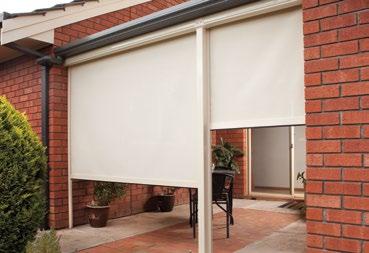


1 AMBIENT BLINDS WINDSOR WIRE GUIDED SEMI RESTRAINED INSTALL GUIDE
2 CONTENTS September 2013 This manual is to be read in conjunction with the Product Specifications & Assembly manual SECTION NO. DESCRIPTION PAGE NO. SECTION 1 ITEMS REQUIRED 1.1 SECTION 2 INSTALLATION 2.1 PART A PREPARING INSTALLATION SPACE 2.1 PART B BRACKET / BOX INSTALLATION 2.3 PART C WIRE GUIDE INSTALLATION 2.4 PART D BLIND INSTALLATION 2.8 PART E BOX COVER INSTALLATION (FOR BOX 120 SYSTEM ONLY) 2.10 PART F TENSION GUIDELINES 2.12 SECTION 3 TROUBLESHOOTING 3.1 DISCLAIMER INTRODUCTION This Installation manual has been produced by Acmeda to supply the necessary information for safe and correct installation of this system. INSTALLERS RESPONSIBILITY Before installing, please read & ensure you understand the safety information and installation instructions as defined in this installation manual. If you do not fully understand these instructions, contact Acmeda for clarification before installing. The Installer is responsible to ensure that all installation personnel have been adequately trained on the safe & correct installation and operation. The Installer is responsible to ensure that a Job Safety Analysis or Safe Work Method Statement is completed prior to installation to identify hazards, to determine appropriate risk control measures and to implement the control measures. The Installer is responsible to ensure that supporting structures are sound and can adequately support the load. The Installer is responsible to ensure that the devises used to anchor the product to the supporting structure are suitable for the application. SAFETY INFORMATION Ensure Job Safety Analysis/Safe Work Method Statement is completed and actions to reduce risks are implemented. Ensure that electrical works are done only by a LICENSED ELECTRICIAN. DO NOT modify any of the components of this system. PERSONNEL REQUIREMENTS Only suitably trained/qualified personnel should undertake installation. DISCLAIMER Acmeda has used reasonable care in preparing the information included in this document, but makes no representations or warranties as to the completeness or accuracy of the information. Information is supplied upon the condition that the persons receiving the information will make their own determination as to its suitability for their purposes prior to use. Acmeda assumes no liability whatsoever for any damages incurred by you resulting from errors in or omissions from the information included herein. Acmeda reserves the right to make changes without further notice to any products to improve reliability, function or design. COPYRIGHT COPYRIGHT ACMEDA 2013 All rights reserved. No part of this document may be reproduced or utilised in any means, by any means, electronic or mechanical including photocopying, recordings, or by any information storage or retrieval system, without the express permission from Acmeda.
3 SECTION 1 ITEMS REQUIRED TOOLS REQUIRED Saw Saw Drill Screw Driver Philips Head & Flat Head Jaw Pliers Allen Key Set Mallet Scissors Punch tool / template Measuring Tape Pencil ADDITIONAL ITEMS REQUIRED (NOT SUPPLIED) To assemble an EXTERNAL WIRE GUIDE, the following non-stocked items are required: Fixings for mounting brackets / hardware (Ensure appropriate fixings are used to suit application) Page 1.1

 Adjustable Stop (x2)")

4 BLIND ITEMS REQUIRED Check that you have all required blind items: 1. Brackets 2. Box Square Required Installation Items 1. Brackets 3. Complete Blind 4. Wire Guide Components + OR OR OR 2. Box Square Required Installation Items + + Bracket Spacers (x2) Adjustable Stop (x2) 3. Complete Blind + 4. Wire Guide Components FACE FIX INSTALLATION FLOOR FIX INSTALLATION SWAGE ADJUSTABLE TERMINAL + 4.2m WIRE (X2) WALL MOUNTING BRACKET (X2) SWAGE ADJUSTABLE TERMINAL + 4.2m WIRE (X2) TURNBUCKLE SET (X2) ROUND EYE PLATE (X2) + OR + + Page 1.2
5 SECTION 2 INSTALLATION PART A PREPARING INSTALLATION SPACE STEP 1 CHECK INSTALLATION SPACE FOR CLEARANCE & STRUCTURAL SUPPORT Check the Installation Space and ensure adequate clearance is provided for the system Minimum clearance above blind roll: 6mm NOTE: For Top Fix Installations allow 5mm from the wall to the edge of the bracket to provide clearance for weight bar end caps. Ensure brackets can be installed into a structurally supporting substrate (This may mean the installer needs to prepare space prior to commencement of installation) Page 2.1
6 STEP 2 CHECK VERTICAL & HORIZONTAL INSTALLATION DIMENSIONS VERTICAL DIMENSIONS Check if top of installation space is level. If H1 H2, corrective actions may need to be considered prior to installation H1 H2 HORIZONTAL DIMENSIONS W1 If W2 W1, W1=Blind Width (proceed to Section C) W2 W1 If W2 < W1, see table for limits X W2 Y Maximum width difference Box 120 Open X 16mm 10mm Y 16mm 10mm If X and Y are within limits (as indicated in the above table) then installation can be completed using W1 as Blind Width. If not consider further actions for squaring the installation space (e.g. packing or alternative bracket selection) Page 2.2
7 PART B BRACKET / BOX INSTALLATION STEP 1 FIX BRACKETS TO WALL / CEILING USING APPROPRIATE FIXINGS TO SUIT APPLICATION OPEN BLIND SYSTEM FACE FIX TOP FIX NOTE: Ensure brackets are installed aligned and level. Refer to deductions for bracket positioning. BOX 120 SYSTEM Box 120 System can be fixed to the wall in the centre prior to fixing the brackets to ensure Box is level. FACE FIX TOP FIX NOTE: Ensure Bracket Spacers are used with Box 120 System Page 2.3
8 PART C WIRE GUIDE INSTALLATION STEP 1 MARK & SECURE BOTTOM WIRE GUIDE FIXING TO WALL OR FLOOR OPEN BLIND SYSTEM X 2 Brackets NOTE: Dimensions refer centre of wire and apply to both Face Fixing and Floor Fixing installations. BOX 120 SYSTEM X 2 Plates NOTE: Dimensions refer centre of wire and apply to both Face Fixing and Floor Fixing installations. Page 2.4

9 STEP 2 ATTACH TERMINAL TO WALL MOUNTING BRACKET FACE FIX - WALL MOUNTING BRACKET Allow approximately 20mm for tensioning Allow 5-10mm before tensioning NOTE: Ensure both Terminals are attached to brackets. FLOOR FIX - ROUND EYE PLATE 20mm 20mm i) Remove 1 Nut & 2 Washers From Stud Terminal ii) Thread Turnbuckle Set onto Terminal iii) Remove Pin & Clip iv) Position Jaw over Round Eye Plate v) Replace & Secure Pin & Clip NOTE: Ensure both Terminals are attached to Round Eye Plates. Page 2.5
10 STEP 3 INSERT WIRE GUIDE FLOAT ONTO WIRE Feed Floating End Cap onto Wire (at both ends) Allow End Cap to Slide along wire NOTE: Repeat on opposite side. STEP 4 ADD ADJUSTABLE STOP (FOR BOX 120 SYSTEM ONLY) NOTES: Ensure Adjustable Stop is inserted after the Wire Guide Float. Do not tighten at this step Repeat on opposite side Page 2.6
11 STEP 5 SECURE WIRE TO TOP TERMINAL Insert Wire through terminal Measure & cut wire approximately 5-10mm above terminal Tighten grub screw securely to retain wire (ensure thread of grub screw does not strip) STEP 6 ADJUST & SECURE ADJUSTABLE STOP TO WIRE GUIDES (FOR BOX 120 SYSTEM ONLY) 5mm (min) NOTE: Ensure that a minimum clearance of 5mm is left between the bottom of the Adjustable Stop and bottom of the Box to prevent the weight bar from twisting. Page 2.7
 Remove retaining screw from the lock ring before inserting blind as shown above. NOTE: Ensure screw is safely stored as it will need to be re-inserted. Page 2.")
12 PART D BLIND INSTALLATION STEP 1 INSERT CONTROL END FIRST THEN SWING IDLER END INTO ADAPTOR GEAR CONTROL Ensure Idler Pin Locks into Adaptor STAR HEAD MOTOR (FOR STAR HEAD MOTOR ONLY) Remove retaining screw from the lock ring before inserting blind as shown above. NOTE: Ensure screw is safely stored as it will need to be re-inserted. Page 2.8
13 STEP 2 REPLACE & SECURE RETAINING SCREW INTO LOCKING RING (STAR HEAD MOTOR ONLY) Screw until tight in order to lock the Motor in position STEP 3 INSERT FLOATING END CAPS INTO END CAP HOUSING Before applying tension to wire guides, insert end cap float into weight bar end caps. If more clearance / space is required, lift the weight bar at one end to insert the second float. NOTE: If ballast is required, insert prior to fitting end cap. For external applications ensure ballast is corrosion resistant and is compatible with aluminium. Page 2.9
14 PART E BOX COVER INSTALLATION (FOR BOX 120 SYSTEM ONLY) STEP 1 SWING BOX COVER INTO PLACE Ensure Cover clips to tab IF the lip of the cover is not location use a pair of pliers to adjust the locking feature up or down as required Page 2.10
15 STEP 2 FIX COVER WITH SCREW OR RIVET (OPTIONAL) Page 2.11
16 PART F TENSION GUIDELINES To complete the installation ensure adequate tension is applied to the wire guides. 40kg of tension is recommended for the system. If a suitable tension meter is not used, the chart/images below provide a guide on how to apply a nominal tension of 40kg Tension Guideline Table Drop No. of Rotations (Face Fix) No. of Rotations (Floor Fix) 1.0m m m m FACE FIX FIX FIX 1. Pull Swage Terminal down to remove slack and hand tighten bottom nut until contact with bracket NOTE: Repeat on opposite side. 2. Apply tension by holding Swage Terminal still and rotating bottom nut as required (No. Of Rotations indicated above) 3. Tighten and lock top nut while supporting Swage Terminal to ensure tension is maintained (repeat on other terminal) FLOOR FIX FIX FIX FIX 1. Pull Swage Terminal down and hand tighten Turnbuckle to remove slack NOTE: Repeat on opposite side. 2. Apply tension by holding Swage Terminal and rotating Turnbuckle as required (No. Of Rotations indicated above) 3. While holding the Turnbuckle Secure both top and bottom nuts to ensure the system is locked (ensure to only lock one at a time) Page 2.12
17 SECTION 3 TROUBLESHOOTING NO. PROBLEM CAUSE SOLUTION 1 Ripples along sides of fabric Blind rolled up for an extended period of time. Not enough weight in weight bar. Installation is not square. This occurrence is inherent to roller systems and is more prevalent in some fabrics. Leave blind down for 1 4 hours; most ripples should disappear. Refer to Product Specs. Add ballast. Check blind roll is installed level. Fabric permanently damaged due to inadequate handling during assembly, transportation, installation or use. Replace fabric and ensure it is handled with care. 2 Blind does not fully open / jams Position of wire guides at base is incorrect. Check if wire guide fixing at floor/base are positioned in line with the Top Terminal. If fixing is too far inwards of the terminal then reposition. Refer to Part C, Step 1 of this document for wire guide positioning details. Incorrect motor stop limits used. Refer to motor instructions to reset stop limits. 3 Uneven weight bar Blind roll is not level, thus weight bar appears uneven. Blind has been operated in excessive wind conditions. Ensure blind is installed level. Check blind roll when the blind is fully raised. If ripples are evident on roll, open blind fully (without the presence of wind) to allow the blind to track down evenly. Raise and lower blind a number of times to check operation. Fabric is not installed straight. Ensure fabric is assembled straight onto tube and weight bar. Page 3.1

18 Ph: stratco.com.au «Scan this QR code with your smart phone to find a Stratco near you. QUEENSLAND NEW SOUTH WALES AUSTRALIAN CAPITAL TERRITORY VICTORIA SOUTH AUSTRALIA WESTERN AUSTRALIA NORTHERN TERRITORY PLEASE NOTE: Photo s for illustration purposes only. All brands and logos/images accompanied by or are trade marks of Stratco (Australia) Pty Limited. Copyright June 2014 BROCAMB Follow us on
MULTI-LINK/UNI-LINK INSTALLATION MANUAL. October 2016
 MULTI-LINK/UNI-LINK INSTALLATION MANUAL October 2016 CONTENTS October 2016 This manual is to be read in conjunction with the Product Specifications & Assembly manual SECTION NO. DESCRIPTION PAGE NO. SECTION
ZIPSCREEN EXTREME INSTALLATION MANUAL. February 2017
 ZIPSCREEN EXTREME INSTALLATION MANUAL February 2017 CONTENTS February 2017 This manual is to be read in conjunction with the Product Specifications & Assembly manual SECTION NO. DESCRIPTION PAGE NO. SECTION
EASY SPRING WAND INSTALLATION MANUAL. April 2018
 EASY SPRING WAND INSTALLATION MANUAL April 2018 CONTENTS April 2018 This manual is to be read in conjunction with the Product Specifications & Assembly manual SECTION NO. DESCRIPTION PAGE NO. SECTION 1
RB12 AERO - DUAL INSTALLATION MANUAL. February 2017
 RB12 AERO - DUAL INSTALLATION MANUAL February 2017 CONTENTS February 2016 This manual is to be read in conjunction with the Product Specifications & Assembly manual SECTION NO. DESCRIPTION PAGE NO. SECTION
R-SERIES FASCIA - 3&4 inch Chain Control PRODUCT SPECIFICATIONS
 R-SERIES FASCIA - 3&4 inch Chain Control PRODUCT SPECIFICATIONS CONTENTS SECTION A OVERVIEW 01 GENERAL SCHEMATICS...01 SYSTEM OPTIONS....02 COLOR OPTIONS......02 SECTION B SPECIFICATION IMAGES 03 ARCHITECTURAL
AUTOMATE FT MOTOR INSTRUCTIONS
 AUTOMATE FT MOTOR INSTRUCTIONS AUTOMATE FT MOTOR [Ø45/5Nm/5rpm] P/N: RB24-6005-069005 DESCRIPTION AUTOMATE FT MOTOR is a multifunction tubular motor offering three different modes of operation; E-type
HiBoy Maverick/Commander Doors Part # HiBoy4 Maverick/Commander Doors Black
 Racing 3191 N Washington St. Suite 2 Chandler, AZ 85225 1 (800) 708-9803 http://www.racing.com HiBoy Maverick/Commander Doors Part # 07-2001 HiBoy4 Maverick/Commander Doors Black Congratulations on your
Rhino Pioneer SXB (44100B, 44101B, 44102B & 44103B) Place these instructions in the vehicle s glove box after installation is complete.
 Place these instructions in the vehicle s glove box after installation is complete.") (44100B, 44101B, 44102B & 44103B) Place these instructions in the vehicle s glove box after installation is complete. Important: Please read these instructions carefully prior to installation. Check the
(44100B, 44101B, 44102B & 44103B) Place these instructions in the vehicle s glove box after installation is complete. Important: Please read these instructions carefully prior to installation. Check the
Installation Instructions Studio Makeup Station
 Installation Instructions Studio Makeup Station 30" and 36" Models 5-light 30" Studio Makeup Station 8-light 30" Studio Makeup Station 6-light 36" Studio Makeup Station 9-light 36" Studio Makeup Station
Top Down Rollstar Shade Installation Instructions
 Top Down Rollstar Shade Installation Instructions Thank you for purchasing your new Rollstar shade. It has been custom-made from the highest quality materials to the dimensions you specified. With proper
Section 13. Tail Rotor Drive. RotorWay International A600 TALON Construction Manual. Section 13. Page A
 RotorWay International Page A Tail Rotor Drive Procedures covered in this section: Install driveshafts and gearboxes; install drive belt and tensioner; fabricate and install tail rotor pitch actuator arms;
Clutch Operated FlexShade NEXD Window shade with heavy duty clutch and 3 hardware profile. Cassette option.
 INSTRUCTIONS INSTALLATION & OPERATION Overview - FlexShade Components Idler 1¼ Roller with Spline Atachment Clutch TOOLS REQUIRED Clutch PENCIL POWER DRILL Idler 1 Eliptical Hem Bar TAPE MEASURE LEVEL
Roller Shades CORD LOOP. Head Rail, Fascia and No Head Rail. Installation & Care Instructions
 Roller Shades CORD LOOP Head Rail, Fascia and No Head Rail Installation & Care Instructions 152038 H 5/30/2017 GETTING STARTED A few simple tools are required: - Measuring tape - Power drill, drill bits
TOYOTA HIGHLANDER RUNNING BOARD HIGHLANDER HV Preparation
 Preparation Part Number: PT738-48080 Kit Contents Item # Quantity Reqd. Description 1 1 Driver Side Running Board 2 1 Passenger Side Running Board 3 4 /Middle Mount Bracket 4 2 Rear Mount Bracket 5 2 Rear
Solar & Roller Shades
 STEP BY STEP INSTALLATION INSTRUCTIONS Solar & Roller Shades 1 2 3 4 5 Motivia Motorization Table of Contents Step 1 - Getting Started....3 Everything You Need A Smooth Set-Up We want you to love your
*1274BAG9* 1274BAG GM 4-6 SUSPENSION KIT N2.0. Thank you for choosing Rough Country for your suspension needs A
 92127400A 88-98 GM 4-6 SUSPENSION KIT N2.0 Thank you for choosing Rough Country for your suspension needs. *1274BAG9* 1274BAG9 Rough Country recommends a certified technician installs this system. In addition
ROLL-A-GLIDE INSULATED ROLLER DOOR. Installation Instructions
 ROLL-A-GLIDE INSULATED ROLLER DOOR Installation Instructions 1. Motor 13. Brush Strips 2. Axle Assembly 14. Curtain Assembly 3. Rigid Link Collars 15. Door Laths 4. Octagonal Plug End 16. Locking Caps
RTS518 - Rhino Heavy Duty 2 & 3 Crossbar System Hyundai iload, imax, i800, H-1.
 RTS518 - Rhino Heavy Duty 2 & 3 Crossbar System Hyundai iload, imax, i800, H-1. NOTE: Please read these instructions carefully prior to installation. Check the contents of kit before commencing fi tment
Skyline 4 Fascia Fabrication & Installation Instructions
 Components Needed Page 2 Tools Needed Page 2 System Diagram Page 3 Instructions Step 1: Install Brackets Page 4 Step 2: Install Pre-assembled Shade Page 4 Step 3: Install Fascia Clip Page 4 Step 4: Cut
RTS510 Rhino Heavy Duty Track Mount System - MITSUBISHI TRITON MK
 RTS510 Rhino Heavy Duty Track Mount System - MITSUBISHI TRITON MK Important: Please read these instructions carefully prior to installation. Please refer to your fi tting instruction to ensure that the
R O A D M A S T E R, I N C.
 R O A D M A S T E R, I N C. BASEPLATE KIT 6 5 14 18 9 20 8 7 19 15 17 16 ITEM QTY NAME MATERIAL 1...2...3 HOLE BACKING PLATE... A-003864 2...4...1/4 x 1 1/2 x 2 SQ. HOLE BACKING PLATE... A-000039 3...4...1/2
Check what you have received against the component checklist and hardware above.
 SSS SSPW SSW SSPB SSB Component Checklist Installation Instructions SYSTEMA Systema Monitor Spring Arm HARDWARE Display Mounting Spacers (x4) 3/4mm Allen Keys Display Mounting Screws Arm Assembly VESA
07-13 GM 1500 WINCH PLATE
 92108000 07-13 GM 1500 WINCH PLATE THANK YOU FOR CHOOSING ROUGH COUNTRY FOR YOUR OFF ROAD NEEDS. Rough Country recommends a certified technician install this kit. In addition to these instructions, professional
Clutch Operated Roller Shade with Fascia Installation Instructions
 Clutch Operated Roller Shade with Fascia Installation Instructions Tools Required for Installation: Power Drill & Drill Bits Installation Screws Level Pliers Measuring Tape Step #1 Bracket Installation
C3 Syncro Drive Proclimb 1100 Installation Instructions
 Revision 4 Nov 8-2013 201A Old Town Road, Sicamous, BC. V0E 2V4 Ph 250-833 3538 Fax 888-716 5903 www.c3powersports.com Thank you for purchasing a ProClimb M, ProCross F & XF SyncroDrive Note: This modification
Belt Installation, Tracking, and Maintenance Guide
 Belt Installation, Tracking, and Maintenance Guide LEWCO, Inc. 2018 706 Lane St. Sandusky, Ohio 44870 USA Phone: (419) 625-4014 Fax: (419) 625-1247 Revised 00/00/18 conveyorsales@lewcoinc.com www.lewcoinc.com
NM-NP Pajero Rhino Heavy Duty - Two Bar Trackmount System
 NM-NP Pajero Rhino Heavy Duty - Two Bar Trackmount System Parts List Important: Please read these instructions carefully prior to installation. Please refer to your fitting instruction to ensure that the
SAFETY THIS PRODUCT IS FOR OFFROAD USE ONLY. ALL LIABILITY FOR INSTALLATION AND USE RESTS WITH THE OWNER.
 SAFETY Your safety and the safety of others is very important. In order to help you make informed decisions about safety, we have provided installation instructions and other information. These instructions
R O A D M A S T E R, I N C.
 R O A D M A S T E R, I N C. 6 13 11 MOUNTING BRACKET KIT Cable Tab 14 12 7 15 9 Cable Tab 2 8 10 ITEM QTY NAME MATERIAL 1... 4...1/2 x 1 3/4 BOLT... 350096-00 2... 2...1/2 x 5 1/2 BOLT... 350108-00 3...
Rear Bumper Installation Instructions
 KEY TO COMPONETS A. 1 ea. Rear bumper B. 2 ea. Mounting L bracket C. 11 ea. M12x1.75 hex head bolt D. 4 ea. M12x1.75 hex head bolt E. 6 ea. M12 Hex head lock nut F. 9 ea. Pressure washer G. 19 ea. M12
2015 Mustang Lightbar (All Models) CDC#
 CDC#") 2015 Mustang Lightbar (All Models) CDC# 1511-7000-01 Components: 1 CDC Lightbar Note: READ instructions before starting installation!!! CDC Part# Driver side bracket 0511-6001-05 Passenger side bracket
2015 Mustang Lightbar (All Models) CDC# 1511-7000-01 Components: 1 CDC Lightbar Note: READ instructions before starting installation!!! CDC Part# Driver side bracket 0511-6001-05 Passenger side bracket
JEEP JK 4 LONGARM. Tools Needed: Thank you for choosing Rough Country for your suspension needs.
 921786000 Thank you for choosing Rough Country for your suspension needs. JEEP JK 4 LONGARM Rough Country recommends a certified technician install this system. In addition to these instructions, professional
PowerAssist. Installation Manual
 PowerAssist Counterweight Assisted Hoist System Installation Manual Design, Manufacture and Installation of Theatrical Equipment Worldwide (315) 451-3440 Fax (315) 451-1766 www.jrclancy.com Table of Contents
Rollstar Shade Installation Instructions
 Rollstar Shade Installation Instructions All Lifting Systems Inside or Outside Mount Thank you for purchasing your new Rollstar shade. It has been custom-made from the highest quality materials to the
SAFETY THIS PRODUCT IS FOR OFFROAD USE ONLY. ALL LIABILITY FOR INSTALLATION AND USE RESTS WITH THE OWNER.
 SAFETY Your safety and the safety of others is very important. In order to help you make informed decisions about safety, we have provided installation instructions and other information. These instructions
R O A D M A S T E R, I N C.
 R O A D M A S T E R, I N C. ROADMASTER, Inc. 6110 NE 127th Ave. Vancouver, WA 98682 15 ITEMS 18,19,20,21,& 22 REQUIRED FOR VEHICLES WITHOUT TOW HOO 19 18 BASEPLATE KIT 20 22 4 21 14 5 11 360-896-0407 fax
SAFETY THIS PRODUCT IS FOR OFFROAD USE ONLY. ALL LIABILITY FOR INSTALLATION AND USE RESTS WITH THE OWNER.
 SAFETY Your safety and the safety of others is very important. In order to help you make informed decisions about safety, we have provided installation instructions and other information. These instructions
RTS507 NISSAN Navara Dual Cab Track Mount System
 Place these instructions in the vehicle s glove box after installation is complete. Parts List Important: Please read these instructions carefully prior to installation. Please refer to your fi tting instruction
Tools Needed: Class 8.8 Class MM 55ft/lbs 75ft/lbs 14MM 85ft/lbs 120ft/lbs 16MM 130ft/lbs 165ft/lbs 18MM 170ft/lbs 240ft/lbs
 921788000 JEEP JK 6 LONGARM Rough Country recommends a certified technician install this system. In addition to these instructions, professional knowledge of disassemble/reassembly procedures as well as
Installation Guide for the JK Wrangler 4-Inch Suspension System with FlexArms
 INSTALLATION GUIDE Installation Guide for the JK Wrangler 4-Inch Suspension System with FlexArms TeraFlex, Inc. Tera5680 Manufacturing, Inc. W Dannon Way 5251 South Commerce West Jordan, UT 84081 Dr. Phone/801.288.2585
Instructions to fit the Snorkel Kit S018 Mazda BT on
 Instructions to fit the Snorkel Kit S018 Mazda BT 50 2011 on Airflow Vector Pty Ltd 4 Collins Rd, Dromana VIC. 3936 1.0 Introduction Airflow Vector Pty Ltd thanks you for your purchase and the trust you
Product Information. December 1, The Cable Connection 52 Heppner Drive Carson City, NV 89706
 Product Information December 1, 2016 The Cable Connection 52 Heppner Drive Carson City, NV 89706 800.851.2961 775.885.1443 Fax: 775.885.2734 E-mail: info@ultra-tec.com www.ultra-tec.com Summary of Cable
TOYOTA YARIS (HB) CARGO NET Preparation
 CARGO NET Preparation") Preparation Part Number: PT347-52110 Kit Contents 1 1 Convenience Net 2 1 Hardware Bag NOTE: Part number of this accessory may not be the same as the part number shown. Recommended Sequence of Application
Preparation Part Number: PT347-52110 Kit Contents 1 1 Convenience Net 2 1 Hardware Bag NOTE: Part number of this accessory may not be the same as the part number shown. Recommended Sequence of Application
WIND RATED ROLLER DOORS INSTALLATION GUIDE
 WIND RATED ROLLER DOORS INSTALLATION GUIDE THESE INSTRUCTIONS ARE PROVIDED FOR THE USE BY EXPERIENCED INSTALLERS OF GARAGE DOORS BY UNDERTAKING THE INSTALLATION OF THIS DOOR, THE INSTALLER UNDERSTANDS
Premium Dry Freight (Plywood) Door Installation REFERENCE FIGURE 1
 Door Installation REFERENCE FIGURE 1") Premium Dry Freight (Plywood) Door Installation A Premium door can be identified as usually having a two-spring balancer, 2 diameter (nominal) rollers, and end hinges with removable covers. If your Whiting
Premium Dry Freight (Plywood) Door Installation A Premium door can be identified as usually having a two-spring balancer, 2 diameter (nominal) rollers, and end hinges with removable covers. If your Whiting
Universal Pioneer Platform (Flat Pack) 42114B/42115B
 42114B/42115B") Place these instructions in the vehicle s glove box after installation is complete. Important: Please read these instructions carefully prior to installation. Check the contents of this kit before commencing
Place these instructions in the vehicle s glove box after installation is complete. Important: Please read these instructions carefully prior to installation. Check the contents of this kit before commencing
Installation Instructions Table of Contents
 Installation Instructions Table of Contents Pre- Installation of Garage Storage Lift 2 Layout the Garage Storage Lift 3 Installing the strut Channels 3 Install the Drive Assembly 5 Install the Drive Shaft
Universal Bench-top Conveyor OPERATOR S GUIDE
 OPERATOR S GUIDE DISCLAIMER LIABILITY LIMITATION: The Buyer of this product accepts full responsibility and understanding for the terms and specifications set forth herein. Con-Trol-Cure makes no claim,
Barlow (and Barient) Winches. Specifications, Parts Lists and Service Information
 Winches. Specifications, Parts Lists and Service Information") Barlow (and Barient) Winches Specifications, Parts Lists and Service Information tes 1. These specification sheets have been re-constructed from photocopies of original Barlow documents which are no longer
Barlow (and Barient) Winches Specifications, Parts Lists and Service Information tes 1. These specification sheets have been re-constructed from photocopies of original Barlow documents which are no longer
SAFETY THIS PRODUCT IS FOR OFFROAD USE ONLY. ALL LIABILITY FOR INSTALLATION AND USE RESTS WITH THE OWNER.
 SAFETY Your safety and the safety of others is very important. In order to help you make informed decisions about safety, we have provided installation instructions and other information. These instructions
MATERIALS HANDLING TECHNICAL MANUAL VOL. 2
 5 Beaver maintains a comprehensive range of rigging hardware items for the most rigorous working environment. Comprising of turnbuckles in all configurations, collared Eyebolts and eye nuts, chain split
Installation Operation Care
 Installation Operation Care Standard Clutch CONTENTS Getting Started: Product View... 1 Tools and Fasteners Needed... Installation: Mounting Types and Window Terminology... Mount the Installation Brackets
NB7FI05SY / NBFI05SY FIAT DUCATO 76mm SERIES 2 NUDGE BAR and 76mm NUDGE BAR
 NB7FI05SY / NBFI05SY FIAT DUCATO 76mm SERIES 2 NUDGE BAR and 76mm NUDGE BAR REPLACES: 24.07.10 REVISED: 22.01.15 To the Fitter, This instruction covers two models of this vehicle. The difference between
Solar & Roller Shades
 STEP BY STEP INSTALLATION INSTRUCTIONS Solar & Roller Shades 1 2 3 4 5 Motivia Motorization Table of Contents Step 1 - Getting Started....3 Everything You Need A Smooth Set-Up We want you to love your
88-98 GM 2-3 SUSPENSION KIT
 92754500 Thank you for choosing Rough Country for your suspension needs. 88-98 GM 2-3 SUSPENSION KIT Rough Country recommends a certified technician installs this system. In addition to these instructions,
600 SERIES STANDARD DUTY STRAIGHT TRACK INSTALLATION INSTRUCTIONS
 600 SERIES STANDARD DUTY STRAIGHT TRACK INSTALLATION INSTRUCTIONS PLEASE READ INSTRUCTIONS THOROUGHLY BEFORE BEGINNING. A. BI-PARTING TRAVEL 1. Before raising track into position, determine location of
R O A D M A S T E R, I N C.
 R O A D M A S T E R, I N C. 14 8 7 MOUNTING BRACKET KIT 4 13 5 6 ITEM QTY NAME MATERIAL 1...6...1/2" x 2 1/2" BOLT... 350099-00 2...2...1/2" x 1 1/2" BOLT... 350095-00 3...8...1/2" LOCK WASHER... 350309-00
1-3/8 Designer Metals Telescoping Traversing Rod Installation Instructions
 1-3/8 Designer Metals Telescoping Traversing Rod Installation Instructions Please read and follow all installation instructions provided for proper operation and enjoyment of your new drapery hardware
LUXAFLEX DUETTE Shades with Hard-Wired Motorisation. Installation Operation Care
 LUXAFLEX DUETTE Shades with Hard-Wired Motorisation Installation Operation Care CONTENTS Getting Started: Product View... 1 Tools and Fasteners Needed... 2 Installation: Installation Overview... 3 Mount
Cetra Assembly Instructions
 99877 Revision F- Complete Series Master Packet If you have any questions concerning these instructions, please call Kimball Office Customer Service. 0 Kimball International, Inc. T 800.8.88 F 8.8.800
R O A D M A S T E R, I N C.
 R O A D M A S T E R, I N C. BASEPLATE KIT Important Note: this bracket will not accommodate the Guardian rock shield, Stowaway or the StowMaster and StowMaster All Terrain tow bars. Item Qty Length Width
STEERING COLUMN FOR CARS WITH 605, 670(500) OR DELPHI(600) POWER STEERING
 OR DELPHI(600) POWER STEERING") by Randy Irwin 1955-57 STEERING COLUMN FOR CARS WITH 605, 670(500) OR DELPHI(600) POWER STEERING Tools Needed: Philips Screwdriver 7/16 Wrench 1/2 Deep Socket And Ratchet Randy Irwin - Technical Writer
by Randy Irwin 1955-57 STEERING COLUMN FOR CARS WITH 605, 670(500) OR DELPHI(600) POWER STEERING Tools Needed: Philips Screwdriver 7/16 Wrench 1/2 Deep Socket And Ratchet Randy Irwin - Technical Writer
SAFETY SENSORS FIELD OF VIEW WILL BE ALTERED WITH USE OF THE REPLACEMENT BUMPER. Injury hazard
 SAFETY Your safety and the safety of others is very important. In order to help you make informed decisions about safety, we have provided installation instructions and other information. These instructions
ECO# 1801 REVISION# 000 ES DATE
 SmokeShield Elevator ECO# 1801 REVISION# 000 ES 10-458 DATE 08/25/2018 ECO# 1801 REVISION# 000 ES 10-458 DATE 08/25/2018 Section 1 Table of Contents Section 2 Safety Check List 2 Section 3 Freight Receiving
720BAG GM 2 FRONT & 4 REAR LOWERING KIT
 *720BAG2* 720BAG2 92720200 07-13 GM 2 FRONT & 4 REAR LOWERING KIT Thank you for choosing Rough Country for all your suspension needs. Rough Country recommends a certified technician install this system.
Installation Operation Care
 Installation Operation Care Alustra Woven Textures Standard and Cassette Roller Shades CONTENTS Getting Started: Product View...1 Tools and Fasteners Needed...2 Installation: Installation Overview...3
WARNING! 2 x Crossbars = 5kg
 WARNING!! ü!! km/h 2 x Crossbars = 5kg? kg - Please refer to your vehicle manufacturers handbook for maximum roof load capacity. - Any load transported on Roof Racks must be evenly distributed. - Instructions
SS1066HF Jeep JK Wrangler Left Hand Drive CRDI4 2.8Litre-I4 Diesel Engine and EGHV6 3.8Litre V6 Gasoline Engine
 SS1066HF Jeep JK Wrangler Left Hand Drive CRDI4 2.8Litre-I4 Diesel Engine and EGHV6 3.8Litre V6 Gasoline Engine Installation Guide Safari SS1066HF Page - 1 of 12 6/10/2009 ITEM PART NO DESCRIPTION QTY
R O A D M A S T E R, I N C.
 R O A D M A S T E R, I N C. 14 ROADMASTER, Inc. 6110 NE 127th Ave. Vancouver, WA 98682 7 13 9 11 8 ITEM QTY NAME PART # 1... 4...1/2 x 1 3/4 BOLT... 350096-00 2... 2...1/2 x 5 1/2 BOLT... 350108-00 3...
R Y T E C. Pharma Seal
 R Y T E C Pharma Seal Installation Manual P.O. Box 403, One Cedar Parkway, Jackson, WI 53037 Phone: 262-677-9046 Fax: 262-677-2058 Rytec website: www.rytecdoors.com Rytec On-line store: www.rytecparts.com
8400 Series Fiber Distribution System
 8400 Series Fiber Distribution System Instructions January 1997 34-7041-4699-1-A 1 Contents: 1.0 General... 3 2.0 System Components... 4 3.0 System Engineering... 5 4.0 Hardware Installation... 7 5.0 Cable
991 ROLL BAR INSTALLATION:
 991 ROLL BAR INSTALLATION: We highly recommend CMS roll bars be fitted by shops with experience in installing roll bars. 1. Move power seats to a location where the four bolts can be removed and remove
SAFETY SENSORS FIELD OF VIEW WILL BE ALTERED WITH USE OF THE REPLACEMENT BUMPER. Injury hazard
 SAFETY Your safety and the safety of others is very important. In order to help you make informed decisions about safety, we have provided installation instructions and other information. These instructions
05-07 F250 6 SUSPENSION KIT
 92158000 05-07 F250 6 SUSPENSION KIT Thank you for choosing Rough Country for your suspension needs. Rough Country recommends a certified technician installs this system. In addition to these instructions,
Do-It-Yourself Battery Pack
 Do-It-Yourself Battery Pack 1 Page D I S C L A I M E R O F L I A B I L I T Y A N D W A R R A N T Y This publication describes the author s opinions regarding the subject matter herein. The author and publisher
Rear bumper cannot be used for towing after installation of the rear bumper relocation brackets.
 921RC7030 GM 88-98 4WD 1500 P/U 3 Body Lift Thank you for choosing Rough Country for all your suspension needs. *RC703BAG2* RC703BAG2 Rough Country recommends a certified technician install this kit. Attempts
Riding Mowers. Z44 and Z52 Accu-Z Razor (S/N and above) SM Service Manual Printed 9/24/09
 SM Service Manual Printed 9/24/09") Riding Mowers Z44 and Z52 Accu-Z Razor (S/N 472620 and above) 23802 357-044SM Service Manual 2006 Printed 9/24/09 Copyright 2006 All rights Reserved Land Pride provides this publication as is without warranty
Riding Mowers Z44 and Z52 Accu-Z Razor (S/N 472620 and above) 23802 357-044SM Service Manual 2006 Printed 9/24/09 Copyright 2006 All rights Reserved Land Pride provides this publication as is without warranty
Check what you have received against the component checklist and hardware above.
 SSS SSPW SSW SSPB SSB Component Checklist Installation Instructions SYSTEMA Systema Monitor Spring Arm HARDWARE Display Mounting Spacers (x4) 3/4mm Allen Keys Display Mounting Screws Arm Assembly VESA
230VAC Power Inverter 400W Owner s Manual
 400W 230VAC Power Inverter 400W Owner s Manual For safe and optimum performance, the Enerdrive epower Inverter must be used properly. Carefully read and follow all instructions and guidelines in this manual
SITRANS F. Ultrasonic Flowmeters. Hi-Precision Mounts. Operating Instructions. Answers for industry.
 SITRANS F Ultrasonic Flowmeters Hi-Precision Mounts Operating Instructions Edition 12/2014 Answers for industry. Preliminary Instructions 1 Reflect Mount Mode 2 SITRANS F Ultrasonic Flowmeters Hi-Precision
SS1135HF Jeep KJ Cherokee CRDI4 2.8Litre-I4 Diesel Engine
 SS1135HF Jeep KJ Cherokee CRDI4 2.8Litre-I4 Diesel Engine Parts List 23/2/2010 ITEM PART NO DESCRIPTION QTY 1 965-133-000 BODY - SNORKEL (SS1130HF) 1 2 000-135-800 3 ½" AIR RAM ASSEMBLY 1 3 965-032-000
Check what you have received against the component checklist and hardware above.
 SA71S SA71W SA71B SA71PB Component Checklist Installation Instructions SYSTEMA Systema Monitor Arm 710mm HARDWARE Display Mounting Spacers (x4) 3mm Allen Key Display Mounting Screws Arm Assembly VESA monitor
SAFETY SENSORS FIELD OF VIEW WILL BE ALTERED WITH USE OF THE REPLACEMENT BUMPER. Injury hazard
 SAFETY Your safety and the safety of others is very important. In order to help you make informed decisions about safety, we have provided installation instructions and other information. These instructions
INSTALLATION INSTRUCTIONS
 2595 INSTALLATION INSTRUCTIONS 2-6 ! IMPORTANT PLEASE DON T HURT YOURSELF, YOUR KIT OR YOUR VEHICLE. TAKE A MINUTE TO READ THIS IMPORTANT INFORMATION. DO NOT INSTALL IF THE TRUCK HAS BEEN LIFTED AND THE
R O A D M A S T E R, I N C.
 R O A D M A S T E R, I N C. BASEPLATE KIT ITEM QTY NAME MATERIAL 1...2...1/2" x 5 1/2" BOLT...350108-00 2...4...1/2" x 1 1/2" BOLT...350095-00 3...2...1/2" x 1 1/2" CARR. BOLT...350362-00 4...8...1/2"
Commercial Kitchen Exhaust Fans
 Coercial Kitchen Exhaust Fans Superior Performance Robust Design Reliable Operation Easy Installation Vertical Exhaust Fans - Type V The Technology THE DESIGN Aluminium mixed flow type impellers have a
Adult Car Plans. A comprehensive guide to help you build an official Soap Box Derby Adult Car
 Adult Car Plans A comprehensive guide to help you build an official Soap Box Derby Adult Car 1 Table Of Contents Introduction...Page 3 Adult Car Floorboard...Page 4 Step One Steering Stop Installation...Page
REMOTE CARAVAN MOVER Installation guide and user information. e-go /10/01/rev 3
 REMOTE CARAVAN MOVER Installation guide and user information Contents 1 1 Introduction 3 Parts List 4 Safety Guidelines 4 Technical Specifications 5 Fitting Guidelines (chassis adapters etc.) 6 Fitting
FLEX CONNECTOR HEAT SHRINK SLEEVE INSTALLATION GUIDE
 FLEX CONNECTOR HEAT SHRINK SLEEVE INSTALLATION GUIDE The information in this publication is provided for reference only. While every effort has been made to ensure the reliability and accuracy of the information
EVO TM 200 AND EVO TM 400 LCD DISPLAY INSTALLATION GUIDE
 EVO TM 200 AND EVO TM 400 LCD DISPLAY INSTALLATION GUIDE The information in this publication is provided for reference only. While every effort has been made to ensure the reliability and accuracy of the
SERIES A & AA ROLLER DOORS INSTALLATION GUIDE
 SERIES A & AA ROLLER DOORS INSTALLATION GUIDE THESE INSTRUCTIONS ARE PROVIDED FOR USE BY EXPERIENCED INSTALLERS OF GARAGE DOORS BY UNDER-TAKING THE INSTALLATION OF THIS DOOR, THE INSTALLER UNDERSTANDS
Sivoia QS Wireless Drapery Lite System
 Sivoia QS Wireless Drapery Lite System English Installation Guide Please Read Before Installing Important Notes - Please Read Before Installing A. Lutron systems are intended for use with only Lutron hardware
R O A D M A S T E R, I N C.
 R O A D M A S T E R, I N C. ROADMASTER, Inc. 6110 NE 127th Ave. Vancouver, WA 98682 2 15 1 17 7 5 4 14 11 13 360-896-0407 fax 360-735-9300 www.roadmasterinc.com ITEM QTY NAME MATERIAL 1...2...QUICK LINK...200008-00
LIFT Drop Spindle Lift Kit E-Z-Go RXV Gas or Electric Installation Instructions
 LIFT-107 6 Drop Spindle Lift Kit E-Z-Go RXV Gas or Electric Installation Instructions Contents of LIFT-107 E-Z-Go RXV Drop Spindle Lift Kit: a (1 ea.) Driver Side Spindle b (1 ea.) Passenger Side Spindle
Table Of Contents. Motor Selection Guide Installation Instructions Operators 20-32
 Table Of Contents Motor Selection Guide 2-12 - Shades, Shutters and Doors - Retractable Awnings Installation Instructions 13-1 - Operator Adaptors - Operator Limit Adjustment - Wiring Considerations -
E-LIFT II+ SYSTEM WITH SPRING LEVER FOR A-SERIES AND FULL FRAME LOOMS
 Congratulations on your purchase of the E-Lift II+ system. This system replaces the action of treadling, eliminating leg strain and fatigue. When you activate the Foot Switch, the motor turns, and selected
NM-NP Pajero Rhino Heavy Duty - Two Bar Trackmount System
 NM-NP Pajero Rhino Heavy Duty - Two Bar Trackmount System Parts List Important: Care Instruction: Clean vehicle roof prior to fi tting Rhino Heavy Duty roof racks. Tools Required: Pneumatic or concertina
Explanatory Information (NOT PART OF ANSI STANDARD)
") 6 Mounting 6.1 Inspection Prior to mounting, all wheels shall be inspected for damage and cracks. Wheels which show any evidence of cracks, abusive handling or abusive storage shall not be mounted. 6.1.1
6 Mounting 6.1 Inspection Prior to mounting, all wheels shall be inspected for damage and cracks. Wheels which show any evidence of cracks, abusive handling or abusive storage shall not be mounted. 6.1.1
Installation Guide for the JK Wrangler 4-Inch Suspension System with FlexArms
 INSTALLATION GUIDE Tera Manufacturing, Inc. 5251 South Commerce Dr. Murray, Utah 84107 Phone/801.288.2585 Fax/801.713.2313 www.teraflex.biz Installation Guide for the JK Wrangler 4-Inch Suspension System
SEALING DIP CAP INSTALLATION GUIDE
 SEALING DIP CAP INSTALLATION GUIDE The information in this publication is provided for reference only. While every effort has been made to ensure the reliability and accuracy of the information contained