Owners Manual. Aerator & Circulators
|
|
|
- Shonda George
- 5 years ago
- Views:
Transcription


 Assembly...... pg11 Control Panel Installation.")


1 Owners Manual Aerator & Circulators Contents Important Safety Instructions pg2 General Owner s Instructions pg2 Unit Specs pg3 2400AF, 3400AF/HAF, 4400AF/HAF Parts pg3 2400AF, 3400AF/HAF, 4400AF/HAF Assembly pg4 8400AF, 2.3AF, 3.1AF, 3.3AF, 5.1AF, 5.3AF Parts pg6 8400AF, 2.3AF, 3.1AF, 3.3AF, 5.1AF, 5.3AF Assembly pg6 Mesh Screen Attachment pg9 Installation Instructions pg10 Circulator Parts (CF Models) pg10 Circulator (CF Model) Assembly pg11 Control Panel Installation pg13 C-25 Timer Control Instructions pg14 C85 / C95 non-metallic Wiring Diagram pg15 3 Phase Startup Procedure pg16 C85 / C95 non-metallic and 3 Phase Control Panel Timer pg , 3400, 4400, 8400, 2.3 Replacement Parts Diagram pg18 3HP & 5HP Replacement Parts Diagram pg19 Maintenance Recommendations pg20 Warranty Policy pg20 Troubleshooting Tips pg21 Customer Repair Form pg23 Registration Information pg24 C Intertek ANSI/UL 778: 2016 Ed.6+R:22Feb2017 CSA C22.2 #108: 2014 Ed.5 Kasco Marine, Inc. 800 Deere Rd. Prescott, WI PH FAX sales@kascomarine.com Rev. 02/08/18
2 Thanks! We at Kasco Marine, Inc. would like to both thank and congratulate you on your purchase of the Pond Aerator or Water Circulator model. We appreciate you choosing Kasco and for your purchase. Your decision to purchase Kasco s Pond Aerator or Water Circulator will not disappoint you. The Pond Aerator or Water Circulator will be a great addition to your body of water. It will help improve the water quality by adding much needed oxygen and circulation. We thank you for choosing Kasco for your aeration needs and want you to be completely satisfied with your purchase. Important Safety Instructions Please read and follow these extremely important safety and handling instructions for your Kasco equipment. Following these instructions will help ensure your safety and the quality performance of your equipment. Under NO circumstances should anyone enter the water with the electrical equipment plugged in and/ or in operation. All Kasco equipment is ETL approved to UL and CSA standards for safety in water. However, it is NEVER recommended to enter the water with the equipment in operation. Caution should be used when dealing with any electrical and/or moving equipment. NEVER run the unit out of water. It will damage the seals and create a dangerous situation for the operator. Extreme caution should be used around water, especially cold water, such as in Spring, Fall, and Winter, which poses a hazard in and of itself. NEVER lift or drag the pond aerator or water circulator by the power cord. If you need to pull the unit to the side of the pond, use the anchoring ropes. Do not use waders in deep ponds/lakes or ponds/ lakes with drop-offs, drastic slopes, or soft bottom material. Do not use boats that tip easily for aerator installation, such as a canoe, and follow all boating safety rules and regulations, including wearing a PFD (Personal Flotation Device). Single phase Pond Aerators or Water Circulators are supplied with an internal grounding conductor and a grounding-type attachment plug. To reduce the risk of electrical shock, be certain that the pond aerator or water circulator is plugged into a GFI protected circuit. 3 phase aerators (2.3, 3.3, 5.3) require a startup test after wiring to ensure proper rotation of the propeller. If the propeller is rotating in the opposite direction, the unit will not perform properly and internal damage to the unit may occur. (See 3 phase startup procedure) Control panels must be installed a minimum of 5ft(3m in Canada) from the inside wall of the pond, unless separated from the body of water by a fence wall, or other permanent barrier that will make the unit inaccessible to persons in the water. Control panels must be installed by a qualified electrician. Ground Fault Circuit Interrupters (GFCI) should be tested upon each installation and every month thereafter to ensure proper operation. General Owner s Instructions INSPECT THE SHIPMENT: Immediately inspect your Kasco Aerator shipment for any visible damages. Also cross reference the parts supplied with the Parts Included sheet to check for shortages. Shortages should be reported immediately to your Kasco Marine distributor or representative and damages reported to your carrier and Kasco. ASSEMBLY & INSTALLATION: Please see the proper Assembly and Installation Instructions enclosed in this manual. Each is specific for your model and size of Aerator. Note: It is extremely important to test the GFI breaker in the control panel upon each installation/reinstallation of the unit to ensure proper functioning. WARRANTY: Kasco Aerators are the result of over 35 years of design and engineering. Kasco products are built to withstand the toughest conditions. Kasco Marine backs each Pond Aerator and Water Circulator with a 2 Year Warranty or 3 Year Warranty depending on the model. This warranty covers any and all manufacturers defects within the warranty period from the date of purchase (See Warranty, Warranty Claim, & Return Policy). USE AND OPERATION: Kasco Aerators are designed and engineered for continuous duty, such as on fish farms or other aquaculture applications, or on-demand use, as needed in a recreational water feature. During flotation operation, the water is pulled from 360 O around the unit and from below the unit. The water is pulled upward and thrust through the flotation collar into the air. Your Kasco Marine Aerator is ready for immediate use (after installation). Make sure to keep the motor housing clean from hard water deposits and/or algae. (See Maintenance Recommendations.) Kasco Aerators and Water Circulators are lightweight, energy efficient, and easy to install and operate. We strive 2
3 to produce products that exceed customer expectations. We hope you enjoy your Kasco Aerator or Water Circulator. Unit Specs Model Voltage Operating amps lock rotor amps single phase aerators 2400AF @115V 3400AF @115V 3400HAF @240V 4400AF @115V 40@115V 4400HAF @240V 20@240V 8400AF @240V 3.1AF @240V 5.1AF @240V 3 phase aerators 2.3AF V AF V AF V HAF V HAF V HAF V 50 Single phase circulators 2400CF 115 5@115V 12@115V 3400CF @115V 18@115V 3400HCF @240V 9@240V 4400CF @115V 40@115V 4400HCF @240V 20@240V 8400CF @240V 40@240V 2400AF, 3400AF/HAF, 4400AF/HAF Parts # Item Part# Qty 1 Aerator 1 2 Float /4-20 x 3 1/2 Phillips Pan Head Screw 4 1/4 split washers /4 (3/4 outer diameter) Flat Washer 6 Float Retaining Clips Optional: (bottom screen installation parts 7-12) 7 3/8-16 x 2-1/2 Hex Head Bolt /8 Flat Washer Bottom Screen cushions Bottom Screen # Item Part# Qty 11 Bottom Screen Clips /8-16 Nylon Lock Nut Not pictured: Mooring ropes Mesh screen (optional) cable ties (optional) Optional Equipment Control Box (C-25 for 120V units or C-85 for 240V units in separate box) (1 - optional) Bottom Screen with mesh and Hardware for Small Float Ring (1 - optional) NOTE: Extra hardware may be included. POND AERATOR TOOLS & SUPPLIES NEEDED Anchors or stakes for installing unit (2 or 3 depending on unit) # 2 Phillips head screw driver Two (or 3 depending on model) 12 pieces of 1 galvanized pipe for weighting ropes (optional) #10 x 1 long or longer screw(s) for mounting the optional C-25 (3) or C-85 (4) 9/16 Socket and Ratchet (for optional bottom screen) 9/16 Wrench (for optional bottom screen) Nylon Tie for cord


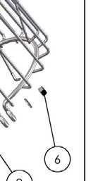
4 2400AF, 3400AF/HAF, 4400AF/HAF Assembly 1. Rest float on the cage Align power cord with notch The 3 bolts should be placed equally spaced around the float in the bolt holes by the indicator mark 2. Secure float to cage with bolts and retaining clips. Lock washer goes between bolt and flat washer. Tighten down in 3 places to the float retaining clips Secure to top ring of cage 6 4


5 Optional Bottom Screen attachment. See Mesh Screen Attachment section before connecting the bottom screen to the float. 3. Turn upside down 4. Place the bottom screen onto the float 5. Place the bottom screen cushions under the float on the 4 bumps OPTIONAL SECTION Secure the bottom screen to the float with the screen clip and hardware. 7. Secure power cord to rope hole. The two prongs on the clip should straddle a wire on the screen 7 8 With Strain Relief Without Strain Relief OR 8. If ready to install in the pond, go to Installation instructions. 5
 # Item Part # Qty 1 Float Sections 284001 3 2 Top Float Bracket 840157 3 3 Bottom Float Bracket w/rope 840158 3 4 9.")

6 8400AF, 2.3AF, 3.1AF, 3.3AF, 5.1AF, 5.3AF Parts POND AERATOR PARTS INCLUDED Aerator Unit with cord (Cord may be shipped separately) (1) B. Large Float Ring (8400AF, 2.3AF) # Item Part # Qty 1 Float Sections Top Float Bracket Bottom Float Bracket w/rope x 3/8 Bolt /8 Lock Nut Unit Mounting Bracket /4 x 3/4 Bolt /4 Lock Washer /8 x 1 Bolt Optional: (parts 10-13) May be sold separately 10 Bottom Screen Clip Bottom Screen Mesh screen Cable ties for mesh B. Large Float Ring (3.1AF, 3.3AF, 5.1AF, 5.3AF) # Item Part # Qty 1 Float Sections Top Float Bracket Bottom Float Bracket w/rope x 3/8 Bolt /8 Lock Nut /8 x 1 Bolt /8 Lock Washer Optional: (parts 8-11) May be sold separately 8 Bottom Screen Clip Bottom Screen Mesh screen Cable ties for mesh Optional Equipment C. Control Box (1 - optional) NOTE: Extra hardware may be included. POND AERATOR TOOLS & SUPPLIES NEEDED Anchors or stakes for installing unit (3) Philips head screw driver for mounting optional control panel 120V or 240V Electrical Supply near pond on a post Three 12 pieces of 1 galvanized pipe for weighting ropes (optional) #10 x 1 long or longer screw(s) for mounting the optional C-25 (3) or C-85/95 (4) 9/16 & 7/16 Nut Driver 9/16 & 7/16 Socket Adjustable crescent wrench Nylon Tie for cord 8400AF, 2.3AF 3.1AF, 3.3AF, 5.1AF, 5.3AF Tools & Supplies Needed: A. Anchors or stakes for installing unit (2 or 3 depending on unit) B V Electrical Supply near pond on a post C. Two (or 3 depending on model) 30cm pieces of 2.54cm galvanized pipe for weighting ropes (optional) D. 9/16 (14mm) & 7/16 (11mm) Nut Driver E. 9/16 (14mm) & 7/16 (11mm) Socket Adjustable crescent wrench 8400AF, 2.3AF, 3.1AF, 3.3AF, 5.1AF, 5.3AF Assembly STEP ONE Remove all contents from package and place on a clean, flat surface. Inspect the shipment for any damages. If damages are found, immediately notify your 6

 upright (plug on bottom) so the overlap of one section aligns")


 with three lock washer and 1/4")
 loosely to the float bracket with (3) 1/4 x 3/4 bolts and 1/4 Lock")


7 carrier and your Kasco Marine, Inc. representative. Next, cross reference the parts included in the shipment with the Parts Included sheet in this manual. Make sure you have all the parts needed. If any shortages are found, contact your Kasco representative immediately. STEP TWO Arrange the three Float Sections (Part #B1) upright (plug on bottom) so the overlap of one section aligns with the next section and loosely push the three sections together to form a continuous ring. 8400AF, 2.3AF STEP FOUR (8400, 2.3) Turn the assembly upside down and place the Bottom Float Brackets (Part #B3) over the bolts, the ends of which should now be extending through the assembly. Loosely install the six 3/8 Lock Nuts (Part #B5) on the ends of the bolts (do not tighten yet). Connect the Top and Bottom Float Brackets using three 1/4 x 3/4 Bolts (Part #B9) with three lock washer and 1/4 nuts and tighten using the 7/16 wrench and socket. 3.1AF, 3.3AF, 5.1AF, 5.3AF Attach the Unit Mounting Brackets (Part #B6) loosely to the float bracket with (3) 1/4 x 3/4 bolts and 1/4 Lock Washers in the top mounting hole as shown STEP THREE Position one Top Float Bracket (Part #B2) so that the bolt holes in the bracket align with the bolt holes in the two adjoined float sections and insert two 9.5 Coated Bolts (Part #B4) through the assembly. This may require some minor repositioning of the float sections as you push the bolt all the way through. Do not force the bolt through. Repeat for the remaining two joints. STEP FOUR (3.1, 3.3, 5.1, 5.3) Turn the assembly upside down and place the Bottom Float Brackets (Part #B3) over the bolts, the ends of which should now be extending through the assembly. Loosely install the six 3/8 Lock Nuts (Part #B5) on the ends of the bolts (do not tighten yet). STEP FIVE See Mesh Screen Attachment section before con- 7
 Lift Float Assembly and place over Aerator Assembly.")
 Raise the Bottom Screen and secure with Bottom Screen clips.")


 and 3/8 Lock Washers (Part #B7) through the top float bracket and lower float bracket as shown and screw directly into Note: Extra hardware may be included")

8 necting the bottom screen to the float. If the optional Bottom Screen (Part#B11) was purchased, place the Aerator Assembly inside the bottom Screen as shown. the aerator mounting ring. Tighten down with a 9/16 wrench. STEP SIX (8400,2.3) Lift Float Assembly and place over Aerator Assembly. Adjust one unit Mounting Bracket at a time and nest the cage ring in the lower notch of the Unit Mounting Bracket for the 3.1, and 5.1 units. Nest the cage ring in the middle notch of the Unit Mounting Bracket. 8400, 2.3 STEP SEVEN (Optional Bottom Screen) Raise the Bottom Screen and secure with Bottom Screen clips. Remove the center three 3/8 Lock Nuts from the 9 Bolts and place the Bottom Screen Clips (Part #B10) over the bolts as shown. The power cord can be slid under the bottom screen between the float and screen where two float sections come together before the 3/8 Lock Nuts are replaced. Replace the three inside Lock Nuts and tighten all 3/8 Lock Nuts using the 9/16 wrench and socket. Once all three Unit Mounting Brackets are seated correctly on the cage ring, add remaining 1/4 x 3/4 Bolts and 1/4 Lock Washers to lower mounting hole. Tighten all bolts on the Unit Mounting Bracket with 7/16 socket or wrench. STEP SIX (3.1, 3.3, 5.1, 5.3) Lift Float Assembly and place over Aerator Assembly. Place the 3/8 x 1 Bolts (Part #B6) and 3/8 Lock Washers (Part #B7) through the top float bracket and lower float bracket as shown and screw directly into Note: Extra hardware may be included STEP EIGHT On power cord lengths of 100 feet or longer with the watertight Quick Disconnect, the power cord is shipped separately. It should now be attached to the stub cord by lining up the male and female halves of the disconnect and hand tightening the blue collar. On these cords, the Additional Strain Relief should be attached to one of the lower float brackets as pictured. If you receive a 3 chain strain relief (6 or 8 gauge cord), attach one chain to each of the three lower float brackets. If there is not Strain Relief, use the Nylon Cable Tie provided to secure the cord to a rope to prevent damage by the propeller. Double check the Quick Disconnect to make sure the threaded collar has not come loose in shipping before placing in the water. If installing a new Quick Disconnect, please refer to Quick Disconnect instructions. 8


 cable ties. 2 inch overlap 3.")


9 mesh cone with approximately 2 inches of mesh overlap to the top ring of the screen. Attach mesh to the top ring of the screen in (3) equally spaced locations using cable ties. 1 chain strain relief Attach 3 cable ties to top ring equally spaced Chain Bottom Float Bracket 3 chain strain relief Mesh Screen Attachment 1. Take flat mesh pattern and wrap into cone shape by overlapping both vertical edges by approximately 1 inch and aligning top and bottom edges of mesh. Secure mesh vertical seam at the top, bottom and middle using (3) cable ties. 2 inch overlap 3. Flip mesh and screen assembly over and use remaining cable ties to secure mesh to small bottom diameter of the stainless steel ring. Attach 2 cable ties to bottom ring equally spaced Overlap vertical edges Attach 3 cable ties 4. Clip off excess cable tie material once mesh is secured into place. Go back to assembly instructions to continue with connecting the bottom screen to the float. 1 inch overlap 2. Insert existing stainless steel screen centered inside 9


 In ponds where the water level fluctuates significantly, you may need to suspend a small weight (12 of 1 galvanize pipe works")
10 Installation Instructions Before installing 3 phase units (2.3, 3.3, 5.3) into the pond, please refer to 3 phase startup procedure. STEP ONE Use the ropes to position the Aerator in the desired location in the pond/lake. Anchor the ropes or secure them to the shoreline so the ropes are free of slack, but not tight. To prevent twisting of the unit due to torque, you should place the anchor at least 3 feet from the float for each foot of depth (Ex. A 6 foot deep pond would require an anchor 18 feet horizontally from the float.) For ease of removal, you may choose to keep at least one anchor within reach from shore, just below the water s surface. Correct Anchoring Incorrect Anchoring STEP TWO (ALTERNATE INSTALLATION) In ponds where the water level fluctuates significantly, you may need to suspend a small weight (12 of 1 galvanize pipe works well) at the mid-point of the rope to take up any slack as the water level drops. The weight should be light enough so the Aerator can rise as the water level rises. This can also help hide ropes by sinking them further below the surface. Normal Water level Anchor Rope Secondary Weight Low Water Level High Water Level Power Cord Kasco Power Control Box STEP THREE At this time the Aerator is ready for operation. It can be plugged into the power supply at the pond edge. ENJOY YOUR NEW KASCO EQUIPMENT! Circulator Parts (CF Models) Circulator (Unit with cord or stub cord) (1) Float in separate box (1) # Item Part # Qty 1 Float Base Strap Adjustment Bracket Angle Bracket Draw Band U-Bracket Spacer Bracket /4 x 1/2 Stainless Steel Bolt /4 x 1 Stainless Steel Bolt /4 x 1-3/8 Stainless Steel Bolt /4 Stainless Steel Lock Nut /4 Stainless Steel Hex Nut /4 Stainless Steel Lock Washer Black Nylon Ropes Nylon Cable tie Draw strap retaining ring Circulator Tools & Supplies Needed A. Anchors or stakes for installing unit (2) B. 120V or 240V Electrical Supply near pond on a post (1) C. 12 pieces of 1 galvanized pipe for weighting ropes (optional) (2) D. 9/16 (14mm) & 7/16 (11mm) Nut Driver E. 9/16 (14mm) & 7/16 (11mm) Socket F. Adjustable crescent wrench G. 7/16 Wrench (1) H. 7/16 Socket & Wrench (1) I. Felt-tip marker (1) 10
upside down (lengthwise channels facing up) and place the Base Strap (Part B2) so the three holes in the Base Strap align with the three threaded holes that")
 4400: 5-1/2 (14 cm) 8400: 7-1/2 (19 cm) STEP THREE Position the Adjustment Bracket (Part B3) over the two holes at the back end of the Float and Base Strap.")
 STEP FOUR Place one of the three Angle Brackets (Part B4)perpendicular to the Base Strap at the front end of the Base Strap.")


11 Circulator (CF Model) Assembly STEP ONE Remove all contents from package and place on a clean, flat surface. Inspect the shipment for any damages. Make sure you have all the parts needed. STEP TWO Position the Float (Part B1)upside down (lengthwise channels facing up) and place the Base Strap (Part B2) so the three holes in the Base Strap align with the three threaded holes that comprise the lengthwise midline of the Float. 2400: 3/4 (1.9cm) 3400: 3-3/8 (8.57cm) 4400: 5-1/2 (14 cm) 8400: 7-1/2 (19 cm) STEP THREE Position the Adjustment Bracket (Part B3) over the two holes at the back end of the Float and Base Strap. Loosely secure the Adjustment Bracket to the Float using two 1/4 x 1/2 (Part B8) Stainless Steel Bolts and two Stainless Steel Lock Washers (Part B13). (See photo above for orientation.) STEP FOUR Place one of the three Angle Brackets (Part B4)perpendicular to the Base Strap at the front end of the Base Strap. One of the two center holes of the Angle Bracket should be positioned over the hole in the Base Strap and the threaded hole in the Float. Secure the Angle Bracket to the Float using three 1/4 x 1/2 Stainless Steel Bolts and three Stainless Steel Lock Washers. (See photos in the next column for specific instructions based on the size circulator purchased.) Tighten all hardware at this time with the 7/16 (11mm) socket and wrench. Models 2400 & Angle posterior to bolts. Model 8400 & 4400 Angle anterior to bolts. STEP SIX Place the two U-Brackets (Part B6) directly across from each other (180 O ) over the top ring of the motor cage. The cord clamp on the cage should be 90 O from each of the U- Brackets. 1/4 x 1 Bolt and Locking Nut 1/4 x 1-1/4 Bolt and Nut Power Cord 1/4 x 1 Bolt and Locking Nut 1/4 x 1-1/4 Bolt and Nut STEP SEVEN Insert the Spacer Bracket (Part B7)under the U-Bracket and inside the cage. Secure this assembly using one 1/4 x 1 Bolt (Part B9) and a 1/4 Lock Nut (Part B11), and one 1/4 x 1-1/4 Bolt (Part B10) and a 1/4 Hex Nut (Part B12). The longer bolt should be on the side of the U-Bracket that is closer to the cord clamp. Tighten the hardware using the 7/16 (11mm) wrench and socket & wrench until the U-Bracket clamps firmly around the cage (U-Bracket should pull together slightly). Repeat with the second U-Bracket. STEP FIVE With a felt-tip marker, draw three to four marks around the circumference of the motor housing at the appropriate measurement from the back (or bottom) of the motor housing given: 11
 around the motor housing and position so that the back of the Draw Band touches the marks drawn in Step")


.")

12 STEP EIGHT Attach an Angle Bracket to each of the longer (1-1/4 ) bolts on the U-Brackets (See photo for orientation) with a 1/4 Lock Nut. most downward) mounting positions for 8400 models. Horizontal Angled Up Angled Down 2400 & & 8400 STEP NINE Wrap the Draw Band (Part B5) around the motor housing and position so that the back of the Draw Band touches the marks drawn in Step Five. There is no front or back to the Draw Band itself - it is reversible. Orient the arm of the Draw Band so it aligns with the cord clamp on the cage of the motor housing and is parallel to the Angle Brackets attached in Step Eight. Secure using a 1/4 x 1 Stainless Steel Bolt and a 1/4 Lock Nut. (See photo in next column) STEP TWELVE Attach the Ropes to the front (on the cage) and back (around the Draw Band) of the motor. At this time, use the Nylon Tie provided to connect the power cord and front Rope to prevent the cord from tangling in the prop. Also, if the power cord has a Quick Disconnect and Additional Strain Relief install the Quick Disconnect and Strain Relief per instructions. STEP TEN Attach the Angle Bracket on the motor to the Angle Bracket on the Float using two 1/4 x 1/2 Bolts and two 1/4 Lock Nuts (one set for each Bracket). See photos for orientation based on model size. Also, the cord clamp on the cage should be oriented toward the Float. Angle towards back Angle Towards front STEP THIRTEEN Float the circulator in the water and position where desired. Tie the front Rope to a stake on the shore or weight. If a weight is used sink weight in front of unit so rope is taught. (Circulators create great force, make sure weight is enough to prevent movement.) Tie back Rope to a stake on opposite shore or weight. Sink weight behind the unit so rope is taught. At this time take up any slack in the line. STEP FOURTEEN You can now connect the Circulator into the GFI protected power source at the ponds edge & & 8400 STEP ELEVEN Attach the Draw Band on the motor to the Adjustment Bracket on the Float using a 1/4 x 1/2 Bolt and a 1/4 Lock Nut. Select one of the five possible positions to mount the Draw Band for your preferred direction of flow. We do not recommend the two outer (most upward and 12
13 Control Panel Installation STEP ONE Inspect the panel for any damage and any components that may have loosened during shipping. Control panel must be installed a minimum of 5ft (3m in Canada) from the inside wall of the pond, unless separated from the body of water by a fence wall, or other permanent barrier that will make the unit inaccessible to persons in the water. Install the control panel to a post structure, side of a building, or other reliable means. This structure must support the panel and prevent movement/flexing of the panel. Use #10 x 1 or longer screws in the mounting points of the control panel to secure to the post structure. NOTE: The control panel must be hung upright in order to be waterproof. It is also advised to mount the panel out of direct sunlight if possible. Mounting the panel in a North direction will prevent heat buildup inside the panel. Also, mount the panel above the potential flood plain to prevent water entry during a possible flood event. STEP TWO Set Timer in the control panel to desired ON and OFF times per the Instructions for each specific timer. STEP THREE Follow all local and national electrical codes for this installation and Consult a qualified electrician or service person if needed. (For 120V Installations) Plug the aerator cord into the C-25 outlet labeled UNIT. If lights are included, plug the Transformer cord into the C-25 outlet labeled LIGHT. Now you are ready to plug the C-25 into the 120V power supply on the post and EN- JOY YOUR NEW KASCO AERATOR! 3 Phase: (2.3, 3.3, 5.3) Refer to your 3 phase control panel instructions Single Phase: (3400H, 4400H, 8400, 3.1, 5.1) STEP THREE (For 240V Installation) All electrical connections to this panel must be made with proper strain relief cord grip fittings or with conduit connections as required by local and national electric codes. The bottom of the enclosure is reserved for field installation of these connections. C85 / C95 non-metallic control panel: Incoming power connection: (Power feed) This control panel requires a 240V or 208V - 4 wire service (L1, L2, N, & G) and must be fed with a power circuit protected by a circuit breaker or a fused disconnect switch to provide circuit protection and a disconnection means. C-85 panel requires at least a 30amp protected circuit feeding the panel. C-95 panel requires at least a 40amp protected circuit feeding the panel. Connect your power feed as detailed in the wiring diagram provided with this panel. L1 connects to Terminal #1 L2 connects to Terminal #2 N connects to Terminal N G connects to Terminal GROUND - located on chassis plate Be sure to provide adequate sized power conductors to prevent excessive voltage drop. Consult with your electrician to properly size power feed conductors. Use copper conductors only. Aerator power cord connection: Your aerator (pump) will be provided with a flexible power cord for connection to this control panel. If the power cord has a plug, you will need to cut it off. The power cord conductors (black, white, green) will need to be stripped back 1/2. The outer black jacket should be stripped back at least 3inches. Follow the connection diagram for terminating these three wires to the terminal blocks in the control panel. Black connects to Terminal #4 White connects to Terminal #5 Green connects to Terminal G Light Kit connection: If you purchased a Kasco light kit(s) for your aerator, follow the light kit installation instructions for mounting the light kit(s) to the aerator float. This control panel requires a hardwire connection for the light kit(s). To connect the light kit(s) you will need to cut off the power cord plug that is molded to the light kit power cord. Strip back the black outer jacket of the light kit power cord at least 3inches to reveal the three internal wires of the power cord. (black, white, and green conductors). These three wires will need to be stripped back 1/2. Follow the connection diagram for terminating these three wires to the terminal blocks in the control panel. 13
14 Light kit connections: Black connects to Terminal #6 White connects to Terminal #7 Green connects to Terminal G STEP FOUR: Test the GFCB with the test button now and every 30 days. If lights are installed, they can now be installed per Instructions included with the lights. Once completed, power can be restored to the panel. Record the following data while the Aerator is operating in the water under load: Voltage: L1-L2 L1-N L2-N Amperage: L1 L2 Date installed / / Any unauthorized modifications to this control panel will void the UL listing and the Kasco warranty. C-25 Timer Control Instructions (Optional Equipment) Portable Timer with Ground Fault Interrupter 1. Push TEST button, RESET button should pop out from inner surface. This should result in power being OFF at the outlet protected by the G.F.C.I. Verify by plugging a test lamp into the outlet. Be sure the timer is in the ON position. 2. If the G.F.C.I. tests okay, restore power by pushing the RESET button back in. THE RESET BUTTON MUST BE PUSHED FIRMLY AND FULLY INTO PLACE UNTIL IT LOCKS AND RE-MAINS DEPRESSED AFTER PRES- SURE HAS BEEN REMOVED. DANGER: IF RESET BUTTON DOES NOT POP OUT, IF TEST LAMP REMAINS LIT WHEN RESET BUTTON DOES POP OUT, OR IF THE G.F.C.I. FAILS TO RE- SET PROPERLY, DO NOT USE TIMER! CONTACT A QUALIFIED SERVICE TECHNICIAN! Failure to use the C-25 with Kasco Fountains will void the warranty and cause the Fountain to not be listed to UL and CSA standards via ETL. UNDER NO CIRCUMSTANCES SHOULD ANYONE ENTER THE WATER WHEN A UNIT IS IN OPERA- TION! TIMER-OPERATION INSTRUCTIONS C-25 Control Box will turn the aerator/fountain ON & OFF with the TIMER. Kasco lights will turn ON with the PHOTO EYE and OFF with TIMER. C-25 Control Box is to be used with Kasco Approved Lights ONLY! See Control panel label for instructions to set the timer Plug aerator/fountain cord into the RIGHT hand outlet (labeled UNIT). Plug transformer light cord into LEFT hand outlet (labeled LIGHT). IMPORTANT This portable timer is designed for CONTROLLING the connected equipment only. Unplug timer before servicing the unit or the equipment it controls. For maximum protection against electrical shock hazard, perform test procedure on G.F.C.I. at least once a month. Mount at least 5 ft. from open water. G.F.C.I. TEST PROCEDURE The G.F.C.I. should be checked every month to make sure that it is operating properly. Just follow the simple instructions below. It is recommended to maintain a maintenance diary of your monthly safety check. 14
15 C85 / C95 non-metallic Wiring Diagram * C95 uses 30 Amp breaker 15
16 3 Phase Startup Procedure If a Kasco Control Panel is not provided, please refer to the following warnings: When inherent overheating protection is not provided: use with approved motor control that matches motor input in full load amperes with overload element(s) selected or adjusted in accordance with control instructions. Utiliser un démarreur approuvé convenant au courant à pleine charge du moteur et dont les éléments thermiques sont réglés ou choisis conformément aux instructions qui l accompagnent. When inherent overheating protection is provided: use with approved motor control that matches motor input in full load amperes. See table below. Utiliser un démarreur approuvé convenant au courant à pleine charge du moteur. Note: The motor input in full load amperes is the marked value or the service factor amperes, shown on the namplate. 3 phase AF 3.3AF 5.3AF 230 Volt Full load amps phase 460 Volt Full load amps 2.3HAF 3.3HAF 5.3HAF Control panels must be installed by a qualified electrician. If unit is connected to a circuit protected by a fuse, use a time-delay fuse with this pump. You must verify motor rotation before installing the unit in the water. 3phase Kasco units will run in a clockwise rotation when looking down at the propeller. Stand clear of the propeller while verifying rotation. If a Kasco 3 phase panel is supplied, follow the intructions with the panel. Also follow the steps below. specified torque setting prior to energizing the panel. 2. Verify the electrical service (voltage and Phase) matches the control panel and aerator nameplates ratings. Refer to the control panel instructions and schematics for installation details. 3. Verify all switches, circuit breakers, and motor starters are in the OFF position 4. Connect electrical service to this control panel as shown in the electrical schematic that came with the panel. 5. Connect the Aerator power cord to this panel as shown in the electrical schematic. 6. Set the motor starter overload to the FLA rating on the aerator nameplate. 7. Pump rotation: The pump rotation is clockwise when looking down at the propeller. Apply power to the control panel. Turn on the 15amp control circuit breaker, and motor starter. 8. Momentarily turn the Hand-Off-Auto switch to Hand. This will run the aerator. Do not run the aerator for more than a few seconds on shore. If the rotation is not correct. Disconnect and lock out power from the control panel. Swap any two of the aerator power cord wires in the panel. This will cause the motor to reverse direction. Reapply power to the panel and verify the rotation is clockwise. 9. Once rotation is verified, with the power disconnected and locked out again, continue with installation of the aerator as detailed in the owner s manual. Record the following data while the unit is operating in the water under load: Voltage: L1-L2 L1-L3 L2-L3 Amperage: L1 L2 L3 Current unbalance should not exceed 5% at full load Electrician: 1. Verify all screw terminal connections are tightened to 16
. Example for 10:00 AM.")
 minutes for each tripper on the 24-Hour dial. When the tripper is pushed to the inside, the switch is in the OFF position.")

17 C85 / C95 non-metallic and 3 Phase Control Panel Timer TIME CLOCK SETTING To set the current time, turn the inner dial clockwise. Do not set the time by rotating outer dial. Turn the minute hand or small plastic inner dial clockwise until the time of day on the outer dial is aligned with the triangle marker on the inner dial (two o clock position). Example for 10:00 AM. Turn the minute hand clockwise until 10:00 AM is aligned with the triangle on the inner dial. The hour and the minute dial will show exactly 10:00. Triangle marker Captive trippers (in the on position) minutes for each tripper on the 24-Hour dial. When the tripper is pushed to the inside, the switch is in the OFF position. PROGRAMMING WITH MANUAL OVERRIDE SWITCH Your Timer may have a 3-way manual switch or a 2-way manual switch. AUTOMATIC MODE In order to operate the time clock in the automatic mode, the manual switch must be in the automatic postion- see diagram. MANUAL MODE For the 3-way switch, with the manual override switch in the lower position, marked O, the time clock output will remain Permanently OFF. In the upper position, marked I, the time clock output will remain permanently ON. For the 2-way switch, with the manual override switch in the lower position, marked ON the time clock output will remain permanently ON. Override Mode 3-way manual override switch I = permanent ON = automatic 0 = permanent OFF ON AUTO PROGRAMMING The 24-Hour dial has quarter-hour divisions and AM/ PM indications. The time switch is programmed by pushing the captive trippers to the outer ring position for the entire period that the aerator is to be turned ON, i.e., fifteen Overide Mode 2-way manual ON - Permanently ON overide switch AUTO - automatic 17


18 , 3400, 4400, 8400, 2.3 Replacement Parts Diagram


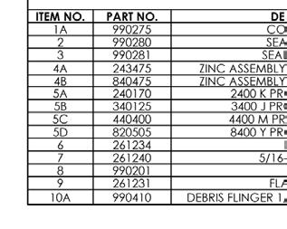
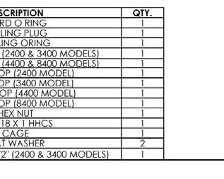
19 ITEM NO. 1 PART NO. SEE CHART DESCRIPTION QTY. PROP, 3HP, A UNIT WASHER, 1/2" ZINC ASSEMBLY 1 3HP & 3HP 5HP & Replacement 5HP AERATORParts REPLACEMENT Diagram PARTS DIAGRAM SEALING PLUG O RING 1 6A O RING, CORD 1 6B O RING, CORD (5.1) RETAINING CLIP LOCK WASHER, 1/4" /4-20 x 3/4" HEX HEAD CAPSCREW RING, AERATOR MOUNTING DEBRIS FLINGER,.625 DIA. SHAFT MODEL NO. PROP NO. 3.1A A & U3.3A HA & U3.3HA A A & U5.3A HA & U5.3HA
20 Maintenance Recommendations Under No Circumstances should anyone enter the water while a unit is operating. Turn Off and Disconnect electrical power prior to any Maintenance or Servicing Ground fault interrupters are a safety feature that can also alert you to electrical leaks in the equipment. It is extremely important to test the GFI upon installation, each reinstallation, and monthly thereafter to ensure proper operation. If you have repeat, consistent trips on your ground fault, the equipment should be disconnected and removed from the water. The power cord should be inspected for damage and you should call a Kasco Marine distributor or representative for further instructions. If the supply cord becomes damaged, it must be replaced by an authorized service center, or similarly qualified persons in order to avoid a hazard. OBSERVATION: Operating equipment should be observed on a regular basis (daily, if possible) for any reduction or variation in performance. If a change in performance is observed, the equipment should be disconnected from power and inspected for any material that may have clogged the system or wrapped around the shaft of the motor, especially plastic bags and fishing line. Even though Kasco Aerators & Circulators are among the most clog-resistant on the market, it is impossible to protect against all items that can clog equipment and still maintain a flow of water. These materials can be very damaging to the equipment under continued operation and must be removed as soon as possible. ALWAYS UNPLUG THE UNIT BEFORE AT- TEMPTING TO REMOVE CLOGS. WINTER STORAGE: In regions where there is significant freezing in the wintertime, Aerators should be removed from the water to protect them from the expansion pressure of the ice. In many areas, Aerators will keep some amount of ice open through the winter. However, when the water is thrust into the air, it is exposed to the colder air temperatures longer and can actually make ice thicker on the pond/ lake. Storage over winter is best in a location that is out of the sun and cool, but above 0 O C. CLEANING: Equipment should be removed from the water at least once per year (at the end of the season in cold climates) to clean the exterior of the system, especially the stainless steel motor housing (can). The motor housing is the surface that dissipates heat into the water and any algae, calcium, etc. build-up will become an insulator that blocks heat transfer. In warmer regions it is recommended that the motor is removed and cleaned at least two to three times per year depending on conditions. In most cases a power washer will be sufficient if the unit and algae are still wet. SEAL AND OIL REPLACEMENT: This is a sealed motor assembly and seals will wear out over time (similar to brake pads on a car). Replacement of the seals and a change of oil after three years may add longevity to the operation of the motor, saving you the cost of more expensive repairs. In warmer climates where the equipment runs most or all of the year, it is a good idea to replace seals more regularly than you would need to in colder climates where the unit is removed from the water for several months. ZINC ANODE: A Sacrificial Zinc Anode is supplied on the shaft of all Kasco Aerators & Circulators for protection of the equipment from corrosion and electrolysis. The zinc anode should be replaced if reduced to half the original size or if white in color. Corrosion from electrolysis is more commonly associated with saltwater or brackish water, but as a matter of precaution, it is important to periodically check the zinc anode in all installations (at least every two to three months). Seal replacement and all other repair services should be performed by Kasco Marine or a Kasco trained Authorized Repair Center. Please contact your Kasco Marine, Inc. distributor or representative for your nearest Authorized Repair Center. Warranty Policy Warranty Period: Models 2400AF, 2400CF, 3400(H)AF, 3400(H)CF,, 4400(H)AF, 4400(H)CF - 2 year Warranty Models 8400AF, 8400CF, 2.3(H)AF, 3.1AF, 3.3(H)AF, 5.1AF, 5.3(H)AF - 3 year Warranty Kasco Marine, Inc. warrants this Pond Aerator or Water Circulator to be free from defects in material or workmanship (except for the ropes, power cord, and propeller) under normal use and service. The Kasco Marine, Inc. obligation under this warranty is limited to replacing or repairing free of charge any defective part within the warranty period. Customer shall pay shipping charges for returning the unit to Kasco or an Authorized Repair Center. THIS WARRANTY IS IN LIEU OF ANY OTHER WAR- RANTIES, EXPRESSED OR IMPLIED, AND ANY OTH- ER OBLIGATION OR LIABILITY WHATEVER ON THE PART OF KASCO MARINE, INC. AND IN NO EVENT SHALL KASCO MARINE, INC. BE LIABLE FOR ANY SPECIAL OR CONSEQUENTIAL DAMAGES. Warranty is void if: The Aerator is not maintained properly according to the Maintenance Recommendations supplied in this Own- 20
21 ers Manual. The Aerator is returned for repair without the power cord or if the unit, control box, or power cord are altered in any way from original shipment. Cuts in the power cord are not covered under warranty. The Aerator is not used with the supplied GFI control box. The Aerator is damaged by unauthorized tampering. The Sacrificial Zinc Anode around the propeller shaft shows significant deterioration. (The Anode must be inspected periodically and replaced if necessary.) Warranty Claim Procedure: The best method for establishing warranty period is by the original receipt. Also, register the Aerator online at: www. kascomarine.com (Under the technical tab) Once the warranty coverage has been established, the unit may be sent to any Kasco Authorized Repair Center for evaluation and repair. Please call Kasco Marine at prior to shipping to receive any updated information and/or Repair Form, then ship to: Kasco Marine, Inc. 800 Deere Rd. Prescott, WI Attn: Repairs Or call Kasco Marine at to locate your nearest Authorized Repair Center. You can also Kasco at Note: Only complete motor assemblies will be accepted for warranty repair. The power cord and all other components must be returned with the motor as originally assembled. Any missing parts will be replaced at the customer s expense and, if determined to have caused the failure, could void the entire warranty. Some parts are essential for structural support during shipping and others, such as the power cord, are essential to properly diagnose potential causes of failure. It is not necessary to return the control box, float, or nozzles with the motor assembly, unless specifically asked to by a Kasco representative. Please include the Repair Form received from Kasco Marine or your local distributor with the shipment. If no Repair Form is available, include your name and physical address for return delivery of the repaired unit and a daytime phone number and/or address for correspondence regarding the warranty claim. Any expedited shipping method for the return of the unit is at the customer s expense. Kasco Marine will return units repaired under warranty at our expense via ground freight within the continental United States. Other Repairs: Most failed equipment can be repaired at substantially lower costs than replacement with new. Please ship according to the instructions in the previous section. Again, it is best to call ahead for updated information and/or Repair Form. Kasco Marine does estimates on repairs at the request of the customer. The request for estimate should be included in the letter that accompanies the returned unit and must include a daytime phone number and/or address. Estimate options are as follows: We will contact the customer with a total after the unit has been evaluated, but before the work is performed. We will repair the unit only if repair costs are under a stated dollar amount. Example: Please repair if total is under $ before shipping charges. All estimates that are rejected for repair will be destroyed unless otherwise directed by the customer. If the customer would like the unit returned, the unit will be restored as closely as possible to the condition in which it was received and shipped at the customer s expense for shipping and handling charges. Billing: All non-warranty repairs will be returned to the customer and billed C.O.D. unless otherwise directed. Kasco Marine also accepts Visa and MasterCard credit card payments. Kasco Marine will call for credit card information upon completion of the repair at the customer s request. All other warranty and repair inquiries should be directed to Kasco Marine, Inc. at or returns@kascomarine.com Troubleshooting Tips Below are some helpful troubleshooting tips. If a problem occurs, please double check the assembly and installation instructions as well as the instructions for the proper control panel. More troubleshooting tips can be found at www. kascomarine.com My Aerator trips the ground fault interrupter in the C-85 or C-95. This is the most common symptom of several possible problems. To correctly diagnose the problem, you will need to collect more information. A Ground Fault Interrupter (GFI) breaker that trips can indicate an electrical service problem, water contamination in the unit and/or cord, bad breaker, control box problems, motor problems, etc. Try to find out the answers to these questions before 21
22 you contact Kasco to narrow down the problem. How long does it take to trip the breaker? Does it always take the same amount of time to trip? How many times has it tripped? Has there been any electrical problems in the area recently? My Aerator seems to run slowly. This can also be a symptom of several possible problems. There could be an electrical problem where the unit is not getting the proper voltage. This could also indicate a problem with the motor of the unit, which needs to be looked at by an Authorized Repair Center. Check that the unit is receiving the proper voltage, and, if so, contact Kasco for further steps. My Aerator hums, but will not start. When I spin the prop with a stick, it starts up. (for single phase units only) This indicated a problem with the Starting Capacitor. Each Kasco Aerator is equipped with a Starting Capacitor to get the unit going when it is first plugged in. If it is operating, but not spinning and can be started by spinning the prop with a stick, the Starting capacitor needs to be replaced by an Authorized Repair Center. chipped or damaged prop that is causing the unit to wobble and not pump properly. When the unit is unplugged, check the prop for damages and replace if damage is found. The GFI breaker trips randomly and sporadically. Sometimes it is a few hours of operation, other times it can be days or weeks. This is referred to as a Nuisance Trip. This usually occurs where the unit is installed a great distance from the initial electric service on the property where the ground stake is placed. It is caused by either induced current in the ground wire or a base voltage difference due to soil ph levels. A possible reso- lution to the problem, contact an electrician and install a local grounding stake. This may eliminate the induced current and any base voltage differences. My Aerator turns itself off and back on without the timer and without tripping the GFI breaker. (for single phase units only) Each Kasco unit has a Thermal Overload built in that will turn the unit off when it overheats. Once the unit has cooled down, it will start back up. If you are noticing these symptoms, the unit should be unplugged immediately because the Thermal Overload will continue to turn on and off until it burns out and damages the motor. The unit should be unplugged and taken out of the water to find the cause of the problem. The problem could be one of many, such as, low water levels, build-up on the unit to prevent heat dissipation, something inhibiting the free rotation of the shaft, etc. If something is caught in the unit or there is a build-up on the unit, remove the debris and, if caught early enough, the unit should be fine. Contact a Kasco representative before restarting the unit. My Aerator flow seems to fluctuate and/or be less than usual. This can occur because of a few different reasons. Most of the time, this symptom is caused from unit being clogged with debris. A mat of weeds, many leaves, plastic bags, etc. can clog up the unit and cause it to be starved of water. If the unit does not have the proper amount of water, the flow or pattern will fluctuate up and down and look sporadic. If you are seeing these symptoms, unplug the unit and clean away the debris that is clogging up the screen. Another possibility if these symptoms are noticed, is a 22
23 Customer Repair Form 800 Deere Rd Prescott, WI Phone: Fax: Repair Contact Form Kasco requires all Repairs sent in MUST be accompanied by this form and marked to Repairs attention. (ex. Attn: Repairs) Repairs returned should include upper pump housing or wire basket for Aerators and De Icers. These parts protect the motor during shipping. Kasco is NOT responsible for shipping damage accrued in return shipment. It is the responsibility of customer to ship and pay freight to Kasco. Do not ship float or control panel with unit, unless otherwise instructed A fee of $60 per hour will be assessed for cleaning excessively dirty units and float disassembly Refer to the Owner s manual for easy to follow troubleshooting rule out site issue. Note: Contact Information Should be that of the person or company to contact for repair. Company First Name Last Name Address City State Zip code Phone # Alternate Phone # Address Preferred method of contact (Circle) Purchase order # Phone Submersible Pump Information (Complete if Light kit Information (complete if sending lights) Parts Included (For office use) sending unit) Model # Model # Unit Serial # Serial # Cord Cord Length: Cord Length: Light Kit Purchased from: Purchased From Float Purchase Date: Purchase Date: Control Panel Additional notes for technician. 23
24 Registration Information Fill in the information below and keep for your records. Model # (Ex. 3.1AF) Serial # (Ex. 5101A311725) Purchase Date: Purchased From: Registration Date: Kasco Marine, Inc. 800 Deere Rd. Prescott, WI Phone (715) * Fax (715) * sales@kascomarine.com
Aerator Model 1812AF Owners Manual
 Aerator Model 1812AF Owners Manual Contents Safety Instructions......2 Unit Specs......2 Battery Information:......2 General Owner s Instructions......2 Float Assembly Parts Included......3 Customer Supplied
Patent Pending. Rev. 8/29/05. Made in the USA
 Patent Pending CONTENTS I. Safety Instructions 2 II. General Owner s Instructions... 3 III. Warranty, Warranty Claim, & Return Policy 4-5 IV. Maintenance Recommendations.. 6 V. C-25 Instructions 7 VI.
Owners Manual. xstream Fountain. Model 2400SF
 Owners Manual xstream Fountain Model 2400SF Contents Important Safety.... pg2 General Instructions.... pg2 Cord Gauge Chart.... pg3 Unit Specs.... pg3 Parts Included.... pg3 Assembly.... pg4 Nozzle Options
Owners Manual. xstream Fountain. Model 2400SF
 Owners Manual xstream Fountain Model 2400SF Contents Important Safety.... pg2 General Instructions.... pg2 Cord Gauge Chart.... pg3 Unit Specs.... pg3 Parts Included.... pg3 Assembly.... pg4 Nozzle Options
a
 CONTENTS I. Safety Instructions II. General Owner s Instructions.. III. Warranty, Warranty Claim, & Return Policy IV. Maintenance Recommendations.. V. C-25 Instructions.. VI. C-75 Instructions.. VII. Parts
Owners Manual J Series Decorative Aerators
 Owners Manual J Series Decorative Aerators Contents Important Safety Instructions.... pg2 General Owner s Instructions.... pg2 Unit Specs.... pg3 Parts Included.... pg3 Assembly Instructions.... pg4 Nozzle
Making A Splash! a
 Making A Splash! I. II. III. IV. V. VI. VII. VIII. IX. X. XI. XII. XIII. CONTENTS Safety Instructions... General Owner s Instructions... Parts Included, Tools Needed, Unit Specs Assembly & Installation
Owners Manual 50Hz Aerator & Circulators
 Owners Manual 50Hz Aerator & Circulators Contents Important Safety Instructions......pg2 General description of equipment and function......pg2 Intended use and limits of use......pg2 Installation requirements......pg2
Making a Splash!
 Making a Splash! I. II. III. IV. V. VI. VII. VIII. IX. X. XI. XII. XIII. XIV. XV. XVI. XVII. XVIII. CONTENTS Safety Instructions.. General Owner s Instructions.. 8400JF Parts Included, Tools Needed, &
Manual PN: Rev 01. Otterbine Barebo Inc. Fractional Series 50Hz Installation Manual
 Manual PN: 75-0009 Rev 01 Otterbine Barebo Inc. Fractional Series 50Hz Installation Manual SAFETY INSTRUCTIONS ALL ELECTRICAL WORK MUST BE PERFORMED BY A QUALIFIED LICENSED ELECTRICIAN AND CONFORM WITH
4400JF (120V) Aerating Fountain Specifications
 Aerating Fountain Specifications") 4400JF (120V) Aerating Fountain Specifications This specification is written and intended to provide bidders the necessary information pertaining to the floating aerating fountain(s) or surface aerator
4400JF (120V) Aerating Fountain Specifications This specification is written and intended to provide bidders the necessary information pertaining to the floating aerating fountain(s) or surface aerator
8400JF (240V Single Phase) Aerating Fountain Specifications
 Aerating Fountain Specifications") 8400JF (240V Single Phase) Aerating Fountain Specifications This specification is written and intended to provide bidders the necessary information pertaining to the floating aerating fountain(s) or surface
8400JF (240V Single Phase) Aerating Fountain Specifications This specification is written and intended to provide bidders the necessary information pertaining to the floating aerating fountain(s) or surface
OWNER S MANUAL. Evolution Series Fountain. 1/2 hp, 115V, 60 Hz
 OWNER S MANUAL Aqua Control, Inc. 6A Wolfer Industrial Drive Spring Valley, IL 66 Ph: 5.66.900 00.77.009 Fax: 5.66.90 www.aquacontrol.com Evolution Series Fountain / hp, 5V, 60 Hz SAFETY INSTRUCTIONS IMPORTANT:
OWNER S MANUAL. Evolution Series Fountain. 1/2 hp, 115V, 60 Hz
 OWNER S MANUAL Aqua Control, Inc. 6A Wolfer Industrial Drive Spring Valley, IL 61362 Ph: 815.664.6400 800.377.0019 Fax: 815.664.4901 www.aquacontrol.com 1/2 hp, 115V, 60 Hz QUICK STARTUP INSTRUCTIONS STEP#1
SUNC1200 / ITEM #40882 SUBMERSIBLE UTILITY PUMP OPERATIONS MANUAL
 SUNC1200 / ITEM #40882 SUBMERSIBLE UTILITY PUMP OPERATIONS MANUAL WWW.SUNRUNNERPOOL.COM Performance Model HP GPH of Water @ Total Feet Of Lift 0 ft. 5 ft. 10 ft. 15 ft. 20 ft. 25 ft. Max. Lift SUNC1200
SPECIFICATIONS OXYMAX SUB-SURFACE AERATION SYSTEM
 SPECIFICATIONS OXYMAX SUB-SURFACE AERATION SYSTEM 1.0 GENERAL 1.1 DESCRIPTION A. Manufacturer shall furnish an aeration system capable of providing more equal distribution of oxygenated water throughout
SPECIFICATIONS ULTIMAX SUB-SURFACE DIRECTIONAL AERATION SYSTEM
 SPECIFICATIONS ULTIMAX SUB-SURFACE DIRECTIONAL AERATION SYSTEM 1.0 GENERAL 1.1 DESCRIPTION A. Manufacturer shall furnish an aspirating directional aerator (aspirator) or a high-flow directional aerator
AUTOMATIC SUBMERSIBLE UTILITY PUMP
 AUTOMATIC SUBMERSIBLE UTILITY PUMP Zoeller is a registered trademark of Zoeller Co. All Rights Reserved. MODEL #1043-0006 Español p. 9 ATTACH YOUR RECEIPT HERE Serial Number Purchase Date Questions, problems,
4" ENVIRONMENTAL E-SERIES PUMPS OWNER'S MANUAL. DANGER warns about hazards that will cause. WARNING warns about hazards that can cause
 4" ENVIRONMENTAL E-SERIES PUMPS OWNER'S MANUAL BEFORE INSTALLING PUMP, BE SURE TO READ THIS OWNER S MANUAL CAREFULLY. CAUTION Fill pump with water before starting or pump will be damaged. The motor on
Operating Manual Includes Pumps: PG-9000 Part #R809606
 Operating Manual Includes Pumps: PG-9000 Part #R809606 Introduction Thank you for selecting the PG Series Pumps from Lifegard Aquatics. Before using this pump please take a moment to review this manual.
SUBMERSIBLE SWIMMING POOL DRAINER
 SUBMERSIBLE SWIMMING POOL DRAINER O W N E R S M A N U A L INSTALLATION, OPERATION & PARTS MODEL PCD-10B Sta-Rite Pool/Spa Group 293 Wright Street, Delavan, WI 53115 Use of electrical appliances around
OPERATING MANUAL. centrifugal fan SAFETY PRACTICES
 2237 MARSHALLTOWN BLVD. MARSHALLTOWN, IOWA 50158 PHONE: (641) 753-5601 TOLL FREE: 1-800-383-5601 FAX: (641) 752-9748 WWW.SPREAD-ALLMFG.NET OPERATING MANUAL centrifugal fan SAFETY PRACTICES 1. Have a qualified
Anthro Mobile Device Charging Carts and Cabinets Owners Manual
 Anthro Mobile Device Charging Carts and Cabinets Owners Manual TECHNOLOGY FURNITURE Hello! Thank you for choosing Anthro. Anthro's Tablet Charging Carts and Cabinets are designed to automatically charge
SUNC3000 / Item #40885
 SUNC3000 / Item #40885 AUTOMATIC POOL COVER PUMP OPERATIONS MANUAL WWW.SUNRUNNERPOOL.COM 1 . Performance GPH of Water @ Total Feet Of Lift MODEL HP Max. Lift 0 ft. 5 ft. 10 ft. 15 ft. 20 ft. SUNC3000 1/3
Otte. erbine Frac. ctiona anuall
 Otte erbine e Barrebo Inc. Frac ctiona al Series CE Insta I anuall llation Ma Manu ual PN: 75-00 010 Rev 01 SAFETY ALL ELECTRICAL WORK MUST BE PERFORMED BY A QUALIFIED LICENSED ELECTRICIAN AND CONFORM
MODEL SCA Installation and Operation Manual Important:
 MODEL SCA Installation and Operation Manual Important: This manual contains specific cautionary statements relative to worker safety. Read this manual thoroughly and follow as directed. It is impossible
The Da-Lite Difference.
 The Da-Lite Difference. Instruction Book for Cosmopolitan Electrol For Sizes Up To 9'x12' DA-LITE SCREEN COMPANY, INC. 3100 North Detroit Street Post Office Box 137 Warsaw, Indiana 46581-0137 Phone: 574-267-8101
HALLMARK INDUSTRIES INC
 Performance Part No. HP. CONVERTIBLE JET PUMP USER S MANUAL GPH of Water @ Total Discharge Pressure of 40 psi Max. Pressure Max suction (shallow well) Max Suction (deep well) Max GPM (@0 head) Max Discharge
L-SERIES PUMPS. Operating Manual. Includes Pumps: L-305 L PONDS
 L-SERIES PUMPS Operating Manual Includes Pumps: L-305 L-310 1-877-80-PONDS www.atlanticwatergardens.com Introduction Thank you for selecting the TidalWave L-305/L-310 series pumps. Before using this pump
The Da-Lite Difference.
 The Da-Lite Difference. Instruction Book for Boardroom Electrol DA-LITE SCREEN COMPANY, INC. 3100 North Detroit Street Post Office Box 137 Warsaw, Indiana 46581-0137 Phone: 574-267-8101 800-622-3737 Fax:
AQUASONIC POOL SPEAKER INSTALLATION GUIDE
 AQUASONIC POOL SPEAKER INSTALLATION GUIDE Clark Synthesis, Inc. 8020 Southpark Circle, Suite 600 Littleton, CO 80120 www.clarksynthesis.com 800-898-1945 ! Thank GENERAL SAFETY INSTRUCTIONS you for purchasing
Instruction Book for. ContouR ElECtRol
 Instruction Book for ContouR ElECtRol IMPORTANT SAFETY INSTRUCTIONS When using your video equipment, basic safety precautions should always be followed, including the following: 1. Read and understand
ESE Series Cast Iron Sewage Pumps
 Owner s Manual ESE Series Cast Iron Sewage Pumps TABLE OF CONTENTS General Safety.................... 2 Specifications..................... 3 Installation.................... 4 & 5 Troubleshooting...................
Patriot Portable Material Hoist 850/1000/2000. Operator s Manual
 Patriot Portable Material Hoist 850/1000/2000 Operator s Manual Manual must be read carefully by all operators before hoist is set-up and used. Failure to follow all directions and warnings for safe mounting
PEDESTAL SUMP PUMP. MODEL # Español p. 11. Zoeller is a registered trademark of Zoeller Co. All Rights Reserved.
 PEDESTAL SUMP PUMP Zoeller is a registered trademark of Zoeller Co. All Rights Reserved. MODEL #1084-0001 Español p. 11 ATTACH YOUR RECEIPT HERE Serial Number Purchase Date Questions, problems, missing
INSTRUCTION BOOK FOR. Cosmopolitan Electrol For Sizes Up To 9' x 12'
 INSTRUCTION BOOK FOR Cosmopolitan Electrol For Sizes To 9' x 12' Important Safety Instructions When using your video equipment, basic safety precautions should always be followed, including the following:
EASY CONNECT CRANE KIT Festoon Conductor Systems
 ASSEMBLY INSTRUCTION MANUAL EASY CONNECT CRANE KIT Festoon Conductor Systems October, 2005 Copyright 2005, Yale Lift-Tech, division of Columbus McKinnon Corporation Part No. 117463-05 Mounting Instructions
Helios. 24 Light 240 Volt Controller. PRODUCT # Instruction Manual.
 Helios 14 24 Light 240 Volt Controller PRODUCT # 702832 Instruction Manual www.titancontrols.net Warnings & Cautions Helios 14 Lighting Controller Overview Instructions for Operation Troubleshooting Tips
Innovatech User Manual. Predator 2400 T H E S U R F A C E P R E P A R A T I O N S P E C I A L I S T S
 Innovatech User Manual Predator 2400 T H E S U R F A C E P R E P A R A T I O N S P E C I A L I S T S CONTENTS Introduction... 3 Delivery... 3 Grinder Specifications... 4 Safety Warning... 4 Controls and
Advanced Netbook Charging Carts for 10 laptops or 20 netbooks
 Advanced Netbook Charging Carts for 10 laptops or 20 netbooks Owners Manual TECHNOLOGY FURNITURE Hello! Thank you for choosing Anthro. This unit has been tested to Underwriters Laboratories U.S. and Canadian
OWNER S MANUAL SUBMERSIBLE UTILITY PUMP
 Model 51101-0 OWNER S MANUAL SUBMERSIBLE UTILITY PUMP Questions, problems, missing parts? Before returning to the store call AQUAPRO Customer Service 8 a.m. - 5 p.m., EST, Monday-Friday 1-844-242-2475
Installation Manual. D3600- Series Duplex Grinder Systems. Contents
 Installation Manual 7353000E D3600- Series Duplex Grinder Systems Features: 36 Diameter Fiberglass Tank Available in 48, 60, 72, 84, and 96 heights LSG Single or LSGX 2 Stage 2HP Grinder Pumps Factory
Installation Manual CS9300-LED. Professional Series Landscape Lighting System
 Installation Manual CS9300-LED Professional Series Landscape Lighting System CS9300 Professional Series LED Landscape Lighting System pg. 1 READ THESE INSTRUCTIONS ENTIRELY BEFORE BEGINNING INSTALLATION!
Buhler Versatile 23XX/24XX, Versatile 9X80, and New Holland Versatile 9X8X SmarTrax MD Installation Manual. P/N Rev A 04/16 E23635
 Buhler Versatile 23XX/24XX, Versatile 9X80, and New Holland Versatile 9X8X SmarTrax MD Installation Manual P/N 016-5030-065 Rev A 04/16 E23635 Copyright 2014, 2016 Disclaimer While every effort has been
Marlow Series Cast Iron Swimming Pool Pumps
 INSTRUCTION MANUAL SECTION 360A AC1683 REVISION C INSTALLER: PLEASE LEAVE THIS MANUAL FOR THE OWNER'S USE. Marlow Series Cast Iron Swimming Pool Pumps 3B28EC 3B32EC PLEASE FILL IN DATA FROM YOUR PUMP NAMEPLATE
CSA CERTIFIED Conforms to UL 507
 Installation tion Instructions Please read and save these instructions! TURBO/MAXX12 Volt All Weather RV Ventilator Fans P/N 00-965001 Deluxe Model 1200T WITH THERMOSTAT P/N 00-965007 Standard Model 3550
8 Light Controller. Instruction Manual. With Light Timer 240 Volts. Product # INNOVATING SINCE 1995
 8 Light Controller With Light Timer 240 Volts Product #703008 Instruction Manual INNOVATING SINCE 1995 1 www.titancontrols.net 8 Light Controller This manual covers the following: Warnings & Cautions 8
NOTE. Installation and Service Manual Dual Planetary Gearmotor Slim Rack Slide Out System
 Installation & Service Manual Slim Rack In-Wall Slide Out System Control Box Part Number 1510000199 Content Copyright LCI/Power Gear Issued: December 2014 #3010002588, Rev. 0E Installation and Service
VADA - V75-S PRODUCT OVERVIEW CONSTRUCTION USAGE LIMITATIONS MOTOR WARRANTY
 PRODUCT OVERVIEW The VADA V75-S submersible pumps are suitable for installation in traditional wells, water deposits, collection tanks, clear watercourses, lakes etc. The V75-S provides a hydraulic system
LIFT MATE BOAT LIFT MOTOR ASSEMBLY. Assembly and Operating Manual.
 LIFT MATE BOAT LIFT MOTOR ASSEMBLY Assembly and Operating Manual www.boatliftmotor.com 03/26/2010 LIMITED WARRANTY Shoreline Industries, Inc. warrants its products shall be free from defects in materials
OBAE, OBAEXU, ON BOARD Battery Chargers
 C O R P O R A T IO N O P E R A T I N G I N S T R U C T I O N S OBAE, OBAEXU, ON BOARD Battery Chargers INTRODUCTION: The OBAE line of chargers are designed for the permanent installation on battery powered
IMPORTANT SAFETY INSTRUCTIONS
 OWNER S MANUAL FLO-MASTER XP2 SERIES PUMPS IMPORTANT SAFETY INSTRUCTIONS When installing and using this electrical equipment, basic safety precautions should always be followed, including the following:
EBARA Fluid Handling
 Model DWU, DWXU Instruction and Operation Manual Dominator Submersible Sewage Pumps EBARA International Corporation Thank you for purchasing this Ebara Stainless Steel Pump. We hope you are pleased with
M-3025CB-AV Fuel Pump
 SAVE THESE INSTRUCTIONS M-3025CB-AV Fuel Pump Owner s Manual TABLE OF CONTENTS General Information... 2 Safety Instructions... 2 Installation... 3 Operation... 4 Maintenance... 4 Repair... 5 Troubleshooting...
SELF PRIMING CHEMICAL SERVICE PUMPS
 SELF PRIMING CHEMICAL SERVICE PUMPS INSTALLATION AND OPERATING INSTRUCTIONS This Manual covers: SELF PRIMING MODEL RANGE J50ECX TO J250ECX STAINLESS STEEL*, and NON METALLIC SEAL PUMP MODEL: SERIAL NO:
Installation Manual. Q Series Quadplex Grinder Systems. Contents
 Installation Manual 7759000A Q4800 - Series Quadplex Grinder Systems Features: 48 Diameter Fiberglass Tank Available in 84, 96, and 120 heights LSG Single or LSGX 2 Stage 2 HP Grinder Pumps Factory Installed
CP series. Submersible utility pump 50HZ STAIRS INDUSTRIAL CO., LTD.
 CP series Submersible utility pump 50HZ STAIRS INDUSTRIAL CO., LTD. CP SERIES - Submersible utility pump The STAIRS CP series submersible utility pump is designed for dewatering and groundwater transferring
SUBMERSIBLE SUMP PUMPS
 SUBMERSIBLE SUMP PUMPS Zoeller is a registered trademark of Zoeller Co. All Rights Reserved. MODEL #1099-0001 Español p. 11 ATTACH YOUR RECEIPT HERE Serial Number Purchase Date Questions, problems, missing
READ THIS MANUAL CAREFULLY BEFORE USING THE PUMP
 OWNER S MANUAL Pond Pump READ THIS MANUAL CAREFULLY BEFORE USING THE PUMP Important Notice: This manual contains important information about the installation, operation and safe use of this product. This
TRAILER WINCH MODELS ST315 AND ST712. General Safety (Continued) Description. Unpacking. General Safety Information.
 Description. Unpacking. General Safety Information.") OPERATION AND MAINTENANCE MANUAL TRAILER WINCH READ CAREFULLY BEFORE ATTEMPTING TO ASSEMBLE, INSTALL, OPERATE OR MAINTAIN THE PRODUCT DESCRIBED. PROTECT YOURSELF AND OTHERS BY OBSERVING ALL SAFETY INFORMATION.
OPERATION AND MAINTENANCE MANUAL TRAILER WINCH READ CAREFULLY BEFORE ATTEMPTING TO ASSEMBLE, INSTALL, OPERATE OR MAINTAIN THE PRODUCT DESCRIBED. PROTECT YOURSELF AND OTHERS BY OBSERVING ALL SAFETY INFORMATION.
INSTALLATION and OPERATION BALL WASHER MODEL NO: BW-001N
 Easy Picker Golf Products, Inc. 415 Leonard Blvd. N., Lehigh Acres, FL 33971 PH: 239-368-6600 FAX: 239-369-1579 Service: 800-982-4653 SALES: 800-641-4653 www.easypicker.com salesdept@easypicker.com INSTALLATION
Important Information
 Boat Lift Boss Installation Instructions For Metal Craft Lifts (Kit 3005.7204) Important Information Before installation, read and understand all instructions and warnings. All 120 Volt units MUST have
The Da-Lite Difference.
 The Da-Lite Difference. Instruction Book for Large Advantage Electrol DA-LITE SCREEN COMPANY, INC. 3100 North Detroit Street Post Office Box 137 Warsaw, Indiana 46581-0137 Phone: 574-267-8101 800-622-3737
The POWER. In PRESENTATION PRODUCTS. Instruction Book for COSMOPOLITAN ELECTROL For Sizes Up To 9'x12' DA-LITE SCREEN COMPANY, INC.
 The POWER In PRESENTATION PRODUCTS Instruction Book for COSMOPOLITAN ELECTROL For Sizes Up To 9'x12' DA-LITE SCREEN COMPANY, INC. 3100 North Detroit Street Post Office Box 137 Warsaw, Indiana 46581-0137
SUBMERSIBLE SUMP PUMPS
 SUBMERSIBLE SUMP PUMPS Zoeller is a registered trademark of Zoeller Co. All Rights Reserved. MODELS #1073-0001, 1075-0001 Español p. 9 ATTACH YOUR RECEIPT HERE Serial Number Purchase Date Questions, problems,
Installation, Operation and Maintenance Manual Stancor SSD & SL Series Pumps
 Installation, Operation and Maintenance Manual Stancor SSD & SL Series Pumps EI-700-008 Rev -- Table of Contents Safety Guidelines 3 Caution 4 Wiring 4 Maintenance 4 Nameplate format 4 Prior to Operation
Installation Manual CS9100-LED. Professional Series Landscape Lighting System
 Installation Manual CS9100-LED Professional Series Landscape Lighting System LED Landscape Lighting System pg. 1 READ THESE INSTRUCTIONS ENTIRELY BEFORE BEGINNING INSTALLATION! Congratulations on your
SEWAGE PUMP MODEL # Zoeller is a registered trademark of Zoeller Co. All Rights Reserved. Español p. 14
 SEWAGE PUMP Zoeller is a registered trademark of Zoeller Co. All Rights Reserved. MODEL #1261-0001 Español p. 14 ATTACH YOUR RECEIPT HERE Serial Number Purchase Date Questions, problems, missing parts?
200 Shadylane Drive Philipsburg, PA Phone: (814) Fax: (814) Service Manual. Model 642E Centrifuge
 Fax: (814) Service Manual. Model 642E Centrifuge") 200 Shadylane Drive Philipsburg, PA 16866 Phone: (814) 342-6205 Fax: (814) 342-4510 www.druckerdiagnostics.com Service Manual Model 642E Centrifuge MODEL 642E SERVICE MANUAL REV: Original Issue 1 CONTENTS
200 Shadylane Drive Philipsburg, PA 16866 Phone: (814) 342-6205 Fax: (814) 342-4510 www.druckerdiagnostics.com Service Manual Model 642E Centrifuge MODEL 642E SERVICE MANUAL REV: Original Issue 1 CONTENTS
Installation Manual. CS9300 Professional Series Landscape Lighting System
 Installation Manual CS9300 Professional Series Landscape Lighting System CS9300 Professional Series Landscape Lighting System pg. 1 READ THESE INSTRUCTIONS ENTIRELY BEFORE BEGINNING INSTALLATION! Congratulations
MOTORIZED FOLDING CAMPER WINCH
 OWNER'S MANUAL MOTORIZED FOLDING CAMPER WINCH With 1200lb Lift Capacity The 12 Volt Motorized Folding Camper Winch is used to raise and lower folding campers with the touch of the switch, eliminating hand
2 HP PADDLE WHEEL AERATOR
 2 HP PADDLE WHEEL AERATOR (Part Nos. PW21, PW23) IMPORTANT SAFETY INSTRUCTIONS READ AND FOLLOW ALL INSTRUCTIONS SAVE THESE INSTRUCTIONS ASSEMBLY MANUAL 2 CUSTOMER SERVICE / TECHNICAL SUPPORT If you have
3 FT CORD Models , , , FT CORD W/GFCI Models , , ,
 POWERLINE XP II Swimming Pool Pump (Light Oak color model) With Automatic Timer 3 FT CORD Models 0-1395-226, 0-1396-226, 0-1397-226, 0-1398-226 25 FT CORD W/GFCI Models 0-1395-220, 0-1396-220, 0-1397-220,
AUTO-BREEZE Cotton Candy Machine Instruction Manual Model #3052
 Part No. 55147 Revised: August 2004 AUTO-BREEZE Cotton Candy Machine Instruction Manual Cincinnati, OH 45241-4807 USA Safety Precautions Auto-Breeze 2 INTRODUCTION Your Floss Machine warranty is described
Model NTX7 Series Automatic Battery Charger User s Manual Rev. 1.0 October 17, 2006
 B R A N D Model NTX7 Series Automatic Battery Charger User s Manual Rev. 1.0 October 17, 2006 For Sales, Support and Service phone: 407-331-4793 fax: 407-331-4708 website: www.xenotronix.com email: information@xenotronix.com
OBE, OBEXU, ON BOARD Battery Chargers
 C O R P O R A T IO N O P E R A T I N G I N S T R U C T I O N S OBE, OBEXU, ON BOARD Battery Chargers INTRODUCTION: These chargers are designed for the permanent installation on battery powered vehicles
OWNER S MANUAL EVOLUTION 3500, 4500, 5500, & 8500 SERIES PUMPS
 OWNER S MANUAL EVOLUTION 3500, 4500, 5500, & 8500 SERIES PUMPS IMPORTANT SAFETY INSTRUCTIONS When installing and using this electrical equipment, basic safety precautions should always be followed, including
FP0S2300X FP0S3000X. Submersible Waterfall/Utility Pumps OWNER S MANUAL. Call Installation/Operation/Parts. English...
 P.O. Box 342, Delavan, WI 53115 Phone: 1-800-365-6832 Fax: 1-800-526-3757 E-Mail: info@flotecwater.com Web Site: http://www.flotecwater.com OWNER S MANUAL Submersible Waterfall/Utility Pumps 3384 0399
Owner s Manual Hydro-X Xtreme Xtractor
 4201 Lien Rd Madison, WI 53704 Owner s Manual Hydro-X Xtreme Xtractor Installation, Operation & Service Instructions Read and Save These Instructions The Phoenix Hydro-X Xtreme Xtractor is the most effective
INSTRUCTIONS AND WARRANTY FOR THE STAND AID MODEL 1501 STAND AID SERIAL #
 MAKERS OF STAND AID, PTA, FREEDOM CHAIR STAND AID MODEL 1501 PO BOX 386 Sheldon, IA 51201 1-800-831-8580 1-712-324-2153 (In Iowa) Fax: 712-324-5210 www.stand-aid.com INSTRUCTIONS AND WARRANTY FOR THE STAND
The POWER. In PRESENTATION PRODUCTS. Instruction Book for BOARDROOM ELECTROL DA-LITE SCREEN COMPANY, INC.
 The POWER In PRESENTATION PRODUCTS Instruction Book for BOARDROOM ELECTROL DA-LITE SCREEN COMPANY, INC. 3100 North Detroit Street Post Office Box 137 Warsaw, Indiana 46581-0137 Phone: 574-267-8101 800-622-3737
Safe-T-element Installation Instructions
 Safe-T-element Installation Instructions For: PTI STEZA (2x2 Burner Configuration) & PTI STEZB (3x1 Burner Configuration) Revision K (May. 3 2012) TABLE OF CONTENTS 1. PREPARATION... 3 1.1 General Safety
INSTALLATION INSTRUCTIONS
 INSTALLATION INSTRUCTIONS Universal Air Series!! NOTE!! Covers the following model: 6000 Series 85-0100B-AZ Rev 0 5/07 To ensure that the system is installed properly, provide your electrician with these
INSTRUCTION BOOK FOR. Tensioned Dual Masking Electrol
 INSTRUCTION BOOK FOR Tensioned Dual Masking Electrol Important Safety Instructions When using your video equipment, basic safety precautions should always be followed, including the following: 1. Read
Installation, Operation and Maintenance Manual Stancor SE, SV, SS & SC Series Pumps
 Installation, Operation and Maintenance Manual Stancor SE, SV, SS & SC Series Pumps EI-700-005 Rev -- Table of Contents Safety Guidelines 3 Caution 4 Wiring 4 Maintenance 4 Nameplate format 4 Prior to
WARNING. Important Notice
 CAL (Color AquaLuminator ) Light and Return Water Flow for Above Ground Pools Owners Manual IMPORTANT SAFETY INSTRUCTIONS READ AND FOLLOW ALL INSTRUCTIONS SAVE THESE INSTRUCTIONS Table of Contents SECTION
Installation Operation Parts
 OWNER S MANUAL BATTERY BACKUP SUMP Installation Operation Parts For further operating, installation or maintenance assistance, Call 98-8-05 PRINTED IN U.S.A. M-8 (/9) RULES FOR SAFE INSTALLATION AND OPERATION
Matala. VersiFlow Series. Instruction and Maintenance Manual
 VersiFlow Series High Flow Multi-Purpose "Versatile " Pump V-3200 1/5HP 150W / Discharge 2 V-3900 1/3HP 250W / Discharge 2 V-4700 1/2HP 400W / Discharge 2 V-5600 1HP 750W / Discharge 2 Instruction and
Dimensions 12/800N 12/1200N D. DC to AC Power Inverters. OWNERS MANUAL for Models: OWNERS MANUAL April ISO 9001:2000 Certified Company
 Manufacturer of Dimensions Inverters 4467 White Bear Parkway St. Paul, MN 55110 Phone: 651-653-7000 Fax: 651-653-7600 E-mail: inverterinfo@sensata.com Web: www.dimensions.sensata.com OWNERS MANUAL April
COOKSON OWNER'S MANUAL
 COOKSON OWNER'S MANUAL FDO-A10 INDUSTRIAL DUTY FIRE DOOR OPERATOR R L I S T E D 3040233 US CONTROL PANEL SERIAL# OPERATOR SERIAL# 9001.DWG ECN 0959 REV 4 SPECIFICATIONS MOTOR TYPE:...INTERMITTENT HORSEPOWER:...1/8
INSTALLATION GUIDE. Universal System for Zero Turn Mowers
 INSTALLATION GUIDE Universal System for Zero Turn Mowers Table of Contents General Information 1 Important Notice to Purchaser 2 Specifications 2 Intended Usage 2 Important Information 3 General Safety
INSTRUCTION BOOK FOR. Dual Masking Electrol
 INSTRUCTION BOOK FOR Dual Masking Electrol Important Safety Instructions When using your video equipment, basic safety precautions should always be followed, including the following: 1. Read and understand
MIL-24/2600Q MIL-24/3200DQ
 Manufacturer of Dimensions TM Inverters 4467 White Bear Parkway St. Paul, MN 55110 Phone: 651-653-7000 Fax: 651-653-7600 E-mail: inverterinfo@sensata.com Web: www.dimensions.sensata.com 121473B OWNER'S
NECO Pumping Systems
 INSTALLATION OPERATION & MAINTENANCE INSTRUCTIONS For Your NECO Pumping Systems PACKAGED CIRCULATING SYSTEM THIS COMPLETELY ASSEMBLED, TESTED, PACKAGED CIRCULATING SYSTEM IS OF THE HIGHEST QUALITY AND
OPERATING MANUAL. aeration fans. models: sa sa sa SAFETY PRACTICES
 2237 MARSHALLTOWN BLVD. MARSHALLTOWN, IOWA 50158 PHONE: (641) 753-5601 TOLL FREE: 1-800-383-5601 FAX: (641) 752-9748 WWW.SPREAD-ALLMFG.NET OPERATING MANUAL aeration fans models: sa-12075 sa-12100 - sa-14100
Utility Distribution Systems Installation, Operation, and Maintenance Manual
 Utility Distribution Systems Installation, Operation, and Maintenance Manual RECEIVING AND INSPECTION Upon receiving unit, check for any interior and exterior damage, and if found, report it immediately
Operator's Manual. Storage System. Ultrasound Probe Cabinet. Manufactured by:
 Storage System Ultrasound Probe Cabinet Operator's Manual Manufactured by: CIVCO Medical Solutions 102 First Street South Kalona, IA 52247 USA 319.248.6757 / 800.445.6741 WWW.CIVCO.COM Copyright 2018 All
SHALLOW WELL JET PUMP
 SHALLOW WELL JET PUMP MODEL FJ05S 1/2 HP flintandwalling.com ATTACH YOUR RECEIPT HERE Serial Number Purchase Date 1 FW1642 B TABLE OF CONTENTS Product Specifications...2 Safety Information...2 Package
GRINDER PUMP MODEL # Zoeller is a registered trademark of Zoeller Co. All Rights Reserved. Español p. 13
 GRINDER PUMP Zoeller is a registered trademark of Zoeller Co. All Rights Reserved. MODEL #2701-0005 Español p. 13 ATTACH YOUR RECEIPT HERE Serial Number Purchase Date Questions, problems, missing parts?
CRD610 Automatic Fitting Inserter
 CRD610 Automatic Fitting Inserter OPERATIONS MANUAL VERSION 1.2 LAST EDITED 12.12.2018 cleanroomdevices.com 1 Table of Contents Title Page. 1 Table of Contents...2 1.0 General Product & Safety Information....3