Filter Manual Installation / Operation Manual
|
|
|
- Jesse Cameron
- 5 years ago
- Views:
Transcription


1 Filter Manual Installation / Operation Manual

2 General Specifications... Page 3 Filter Media... Page 4 Installation Requirements... Page 5 Programming the Control Valve... Page 9 Utilizing Bluetooth... Page 11 Master Programming... Page 14 Control Valve Powerhead Assy. ISO II & ISO III... Page 15 Valve Body Assembly ISO II... Page 16 Bypass Assembly ISO II... Page 17 Valve Body Assembly ISO III... Page 18 Bypass Assembly ISO III... Page 19 Service Instructions... Page 20 Troubleshooting... Page 21 Error Codes... Page 22 Warranty Information... Page 23 Register Your Product Online at 2
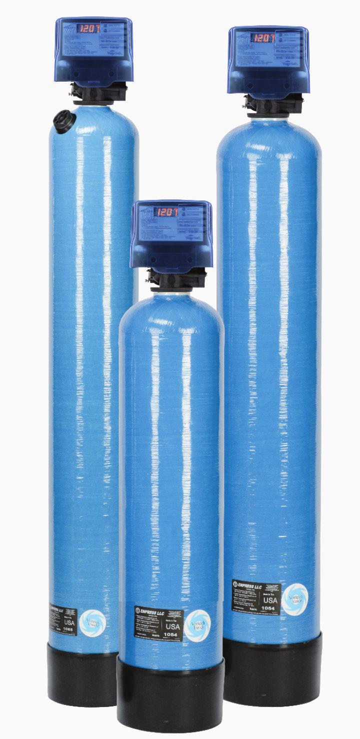
3 Filter Specifications General Specifications Filtration 1 G9 G9-3 G10 G10-3 G12 G12-3 Less Filter Media G13 G13-3 Filter Media Capacity (cu ft) G14 G14-3 Mineral Tank (Vortech ) 9 X X X X X 65 Service Flow Rate - Continuous 2 (gpm) Service Flow Rate - Intermittent 2 (gpm) Backwash Flow Rate 3 (gpm) Gallons Used / Backwash Space Required 9 X 9 X X 10 X X 12 X X 13 X X 13 X 74 Approximate Shipping Weight (lbs) See Filter Media section for selection of proper media for your filtration application. 2 Use of a flow control in the Service line is highly recommended. 3 Caution should always be used in sizing filters! Always choose a unit by first satisfying the Backwash Flow Rate requirement above. Consult the factory or your field sales person with questions. WARNING Lubricants Do NOT use Vaseline, oils, hydrocarbon lubricants or spray silicone anywhere! Petroleum base lubricants will cause swelling of o-rings and seals. The use of other lubricants may attack plastic Noryl. It is recommended that Dow Corning silicone grease be used as a lubricant for all control valves. Dow Corning 7 Release Compound is used in the manufacture of Chandler Systems control valves. (Part # LT-150) Sealants Pipe dope and liquid thread sealers may contain a carrier that attacks some plastic materials. It is recommended that Teflon tape be used to seal plastic Noryl threaded fittings. 3
4 Filter Media Media Ship Wt. (lbs) Description Handles... Used in... SmartBlend SB75 SB Granular / White-Black / Filter Ag Plus and Katalox Light / Max life expectancy about 8-10 years but is dependent upon ph Sediment Iron (clear & red) Manganese (clear & red Sulfur Particles PROVECTR Soft N Filter w/ Mid-Vortech 4 CENTURI Neutralizer NE50 NE75 NE Granular / White / Sacrificial to water with ph, 7.0 / Max ph correction to 7.2 / Lowest ph application 5.8 / Must be replenished about every 3-6 months Sediment ph correction G Series Filters U Series Filters 2 Soft N Filter w/ Mid-Vortech Neu-Cor NC75 NC Granular / Semi-round / White & Off-white / 70%-30% Blend of Neutralizer & Corosex must be replenished on a regular basis since both components are sacrificial to low ph / Use on ph levels as low as 5.06 Sediment (downflow) ph Correction G Series Filters U Series Filters Corosex CX75 CX Semi-round / Off-White / Magnesium Oxide / Extremely reactive to ph dissolving rapidly adding alkalinity / NEVER use 100% Corosex in a filter as it will cement / 30% Corosex - 70% Neutralizer is best blend for correcting low ph / Will raise ph from lows around 5.0 to as high as 9.0+ / Must be replenished frequently / consult factory with specific application questions Sediment (downflow) ph Correction G Series Filters 5 U Series Filters 5 Coconut Shell Carbon CN75 CX Black / High carbon-low ash content. Practical for ordinary taste, odor and chlorine loads. Will impart a high polish to the filtered water. Taste/Odor/Color G Series Filters 5 U Series Filters 5 Activated Carbon AC75 AC Granular / Black / Wide application for removal of organics and some inorganics / Must be replaced on a regular basis / Life expectancy varies based on use Sediment Taste/Odor/Color Chlorine/Iodine G Series Filters U Series Filters Soft N Filter w/ Mid-Vortech Drinking Water Filters Catalytic Carbon CC75 CC10 Filter Ag FA75 FA10 Filter Ag Plus FP75 FP Granular/Black / enhanced activated carbon that has a higher catalytic power which produces an increased electron transfer for better absorption. Granular / Off-White / Wide application for removal of sediment / Life expectancy is unlimited Sulfur Removal Chloramine Sediment PROVECTR G Series Filters City Soft G Series Filters Soft N Filter w/ Mid-Vortech Light tan to white, 5 micron filtration Sediment G Series Filters Birm BM75 BM Granular / Gray / Must not be used on waters with a ph < 6.8 / Must have dissolved oxygen present at a level of at least 15% of iron & manganese ppm / Max iron & manganese level 10 ppm / Estimated life about 8-10 years Sediment Iron (clear & red) Manganese (clear & red) G Series Filters Soft N Filter w/ Mid-Vortech 3 Greensand Plus GP75 GP Granular / Black / Must not be used on waters with a ph <6.8 / Must be regenerated with potassium permanganate on a regular basis / Max iron & manganese level 10ppm/ Max H2S level 3ppm / Estimated life about 8-10 years Sediment Iron (clear & red) Manganese (clear & red) Hydrogen Sulfide GIP Series Filters D Gravel DG20 DG Semi-Round / Brown / #20 Flint / Used as underbed for all media in all filters providing for excellent flow distribution in both service and backwash modes / Permanent unless fouled but can be cleaned and re-used. Underbed All Non Vortech Filter Systems 4
5 Installation Installation Requirements A level floor position ahead of piping into water heater. Unit must be installed at least 10 ahead of the inlet to a water heater to prevent damage due to back-up of hot water. DO NOT install the unit in an area of direct sunlight or where freezing temperatures may occur! (See Installation Diagrams for proper placement and plumbing connections.) 5
6 Installation Note: If household plumbing is galvanized and you intend to make the installation with copper (or vice versa), obtain di-electric unions to prevent dissimilar metal corrosion. All plumbing lines not requiring soft water should be connected upstream of the softener, if installed. (See Typical Installation Diagrams.) Caution: If sweat soldering copper pipe (remember to always use lead free solder and flux), cover yoke and bypass valve with wet rags to prevent heat damage to connections and control valve. If using PVC or plastic pipe, primers and solvent cements specifically recommended for use with potable water are required. 6
7 Installation Installation Procedure - Water Supply Connection and Bypass Valve - To allow for filter servicing, swimming pool filling or lawn sprinkling, a manual Bypass Valve has been installed at the factory. The Bypass allows raw water to be manually routed around the filter. 1. Position filter at desired location for installation. If a water softener is to be installed, the filter should be positioned first and then the softener. (See Installation Diagrams.) 2. The filter material is shipped separately from the mineral tank. The tank must be loaded with material after tank has been placed at the desired location. A. Remove the control valve by unscrewing from the tank. (Do not fill through dome hole, if installed.) B. Use cap provided to place over top of distributor tube to prevent material from entering tube while filling. C. Place media funnel (part # U-1006) in hole on top of tank. D. Pour several gallons of water in the tank. (Fill tank about 1/3 full.) E. Pour in the required filter media. No gravel is required. The required quantity of media is listed in the filter specifications. Note: If rebedding an existing unit and the system utilizes a standard tube & basket style distributor, a D gravel underbedding will be required. F. After filling the tank with material, use a garden hose or several buckets to fill the tank with water. This will permit the filtering media to become soaked while preparing the installation and will prevent the control valve from being plugged with floating material on initial backwash. G. Remove funnel and clean filter media from tank threads. H. Remove cap from distributor tube. I. Replace control valve on mineral tank. Do not use Teflon tape or paste on valve threads, as the valve to tank o-ring seals this joint. Caution: Be extremely careful to position distributor tube into control valve distributor tube pilot hole. 3. Turn OFF main water supply and OPEN nearest faucet to relieve pressure. 4. Cut main line and install appropriate elbows and extensions. Caution: Raised arrows located on the sides of control valve body and bypass valve indicate proper direction of water flow. Install inlet and outlet piping in direction of arrows. It is recommended that a vacuum breaker be installed on the inlet plumbing. Bypass - Shown 7

8 Installation - Drain Line Connection - 1. The drain line flow control assembly is pre-assembled for your convenience. Should you choose to hard plumb the drain line, please remove the barb fitting. The flow control housing can be removed by removing the clip and pulling straight out on housing. Note: When re-installing the drain line flow control housing, be sure you hear and feel the O-Ring pop into place before inserting the clip. 2. Install 1/2 I.D. drain line tubing (not included) from hose barb to an open drain. A 4 gap between end of the drain line and the open drain is required to prevent waste water backflow. Keep the drain line as short as possible. An overhead drain line can be used if necessary, but should discharge below the control valve. A syphon trap (taped loop) at the outlet of the drain line is advisable to keep the drain line full and assure correct flow during backwash. Elbows or other fittings must be kept at a bare minimum. Note: Where the drain line is elevated above the control valve or exceeds 20 feet in length, 3/4 I.D. drain line tubing should be used. Electrical Connection - 1. Connect the power supply to the control valve and plug into a 115 volt / 60 Hz receptacle. Note: Do not plug into an outlet controlled by a wall switch or pull chain that could inadvertently be turned off. Electronic Connections P - Power Supply P B S B - Powered in Backwash Step Only (Cycle #1) S - Powered in Entire Regeneration Cycle - Pressurizing The System - 2. Slowly rotate handle of the bypass valve to the SERVICE position. 3. Open the nearest faucet to evacuate air from plumbing lines. 4. Check for leaks! If water is observed leaking from bypass, o-rings on valve body may not be seated properly. Exercise bypass valve. 5. After air is evacuated from plumbing lines, turn off faucet. - Initial Control Valve Operation - 1. Advance control valve to BACKWASH (cycle 1) position and allow water to run to drain for 3 to 4 minutes. Warning: Close handle on bypass prior to selecting the backwash position. After backwash position has been established, slightly open valve on bypass to evacuate air from the media tank. Fully open bypass valve when all air is depleted. This procedure will prevent media form being uplifted into control valve. 2. Advance control valve to RAPID RINSE (cycle 3) position and allow water to run to drain for 3 to 4 minutes. 3. Advance control valve to SERVICE (cycle 0) position. 8
9 Programming the Control Valve - Final Checkout - 1. Be certain that the bypass valve is in Service position and main valve is completely on. 2. Check electrical supply to be certain the cord is connected to an uninterrupted 115 volt outlet. 3. REGISTER YOUR PRODUCT at 4. Leave this manual with the homeowner. Important Notice - The plumbing system, piping, pressure tank, hot water tanks, softeners, etc. that have been exposed to iron bearing water may need to be cleaned of the precipitated iron that has been collected in them or iron bleed thru may be a problem. We suggest all tanks be drained and flushed thoroughly. - Programming The Control Valve - 1. Set time of day. 2. Set a.m. or p.m. 3. Set number of days between backwash. (This generally will be every 4 to 6 days.) 1. Set regeneration time if other than 12:00 a.m. is desired. Main Menu 12:00 1. To enter Main Menu, press the Menu/Enter button. (Time of Day will flash) 2. To set the Time of Day, press the Set/Change button. (First digit will flash) Example (12:00) - To change digit value, press the Set/Change button. - To accept the digit value, press the Menu/Enter button. - Next digit will flash to begin setting. - Once the last digit display is accepted, all digits will flash. 3. To set A.M. or P.M., press the Menu/Enter button. - To change digit value, press the Set/Change button. Example ( A ) - To accept the digit value, press the Menu/Enter button. - Once A.M. or P.M. is accepted, the next menu item will flash. 4. a. To set the Number of Days between Backwash Cycles (A), press the Set/Change button. - Repeat instructions from step (2). Example ( A - 06 ) Notes: 1) Maximum value is 29. 2) If value set to 0, Automatic Backwash will never occur. 3) Default setting is 6 days for filters. 5. To Exit Main Menu, press the Menu/Enter button. Note: If no buttons are pressed for 60 seconds, the Main Menu will be exited automatically. 9
10 Programming the Control Valve Normal Operation 1. Home Display a. Alternates between the display of Time of Day and Number of Days until the Next Backwash. (Metered Softeners will alternate between time of days and gallons remaining until next regeneration) - Days Remaining until the Next Backwash will count down from the entered value until it reaches 1 day remaining. - A Backwash Cycle will then be initiated at the next designated regeneration time. 2. Battery Back-Up (Uses a standard 9-volt alkaline battery.) Features of Battery Back-Up: During power failures, the battery will maintain the time of day as long as the battery has power. The display is turned off to conserve battery power during this time. To confirm that the battery is working, press either button and the display will turn on for five (5) seconds. If power failure occurs while system is regenerating, the Isobar 2 will motor to a shut off position to prevent constant flow to drain. Depending upon system pressure and other factors, it is possible to observe a reduced flow to drain during this step. After power is restored, the Isobar 2 will return and finish the cycle where it left off prior to the power interruption. When used without battery back-up, during a power failure, the unit stops at its current point in the regeneration position and then restarts at that point when the power is restored. The time will be offset by the increment of time the unit was without power, so it is necessary to reset the time of day on the unit. No other system will be affected. Starting Extra Regeneration Cycle 1. To Start Delayed Extra Cycle Example ( 1 ) - If Days Remaining Until Next Backwash does not read 1, press and hold the Set/Change button for 3 seconds until the display reads 1. - Backwash cycle will initiate at the next designated backwash time. 2. To start Immediate Extra Cycle First complete above step. - With Days Remaining Until Next Regeneration at 1. - Press and hold the Set/Change button. - After 3 seconds, the backwash cycle will begin. 3. To Fast Cycle thru regeneration First complete above 2 steps. Note: Press and hold the Set/Change button for 3 seconds to advance to the next cycle step. Fast Cycle is not necessary unless desired to manually step through each cycle step. (Repeat until valve returns to the home display) Filters Default (Min) Step 1 Backwash 10 Step 2 Rest 5 Step 3 Rapid Rinse 10 Step 4 Not Used 0 10


11 Utilizing Bluetooth Control For simplified set up and control, please install the Legacy View on a compatible Bluetooth 4.0+ enabled smart phone or tablet. 1. Download and install the Legacy View app from the Google Play Store, Apple App Store 2. Open the Legacy View app Choose a valve device at any time from the list of available devices to connect to by clicking on it. If the valve you want to connect to doesn t show up, or there is a problem connecting to a device you can press the Scan for Devices button or the Legacy View logo at any time to refresh the list and start the process over. If the valve device is a BTLE valve and it has a password other than the default password, the first time you connect to it the app will ask you to enter the password. After entering it the first time you should not need to enter it again unless it changes. 3. BTLE Valve devices can be updated by the App. When the app is updated from the Google Play Store or the Apple App Store, it may contain an updated firmware program for the valve devices. These updates could contain new features or operational improvements. It is up to the user to allow these updates to be sent to the valve device. Uploading a new program takes approximately 1 minute. Dashboard NOTE: Consult your dealer before making any changes From the Dashboard, all items in ORANGE can be changed, while blue fields are informational only. If you are unsure about the function of the field click the for more information. 11


12 Utilizing Bluetooth Control 1. Change Time of day (Press set to set time automatically based on device time) 1. Set Backwash Frequency This sets the amount of days between backwash cycles. 1. Set Regeneration Time Example: For 2am, just type 2 and press OK. 12


 this device may not cause harmful interference, and (2) this device must accept any interference received, including interference that may cause")


13 Utilizing Bluetooth Control Utilizing Bluetooth Control Status and History From the Status and History, all items in ORANGE can be reset. Touch any table to explode a detailed list of the last 60 days. 1. Start a regeneration or backwash cycle Option 1: Click the Regenerate Unit Now. If you would like to force the unit into the next cycle step click Go to Next Regeneration Step. Option 2: Regenerate Unit at Next Regen Time button. This will take the system into a backwash cycle at the next regeneration time. FCC ID: Name of Grantee: Equipment Class: Notes: SWPLV-019 or SWPEV-019-BLE CHANDLER SYSTEMS, INC. Part 15 Low Power Communication Device Legacy View Valve This device complies with part 15 of the FCC Rules. Operation is subject to the following conditions: (1) this device may not cause harmful interference, and (2) this device must accept any interference received, including interference that may cause undesired operation. Changes or modifications not expressly approved by the party responsible for compliance could void the user s authority to operate the equipment. NOTE: This equipment has been tested and found to comply with the limits for a Class B digital device, pursuant to Part 15 of the FCC Rules. These limits are designed to provide reasonable protection against harmful interference in a residential installation. This equipment generates, uses and can radiate radio frequency energy and, if not installed and used in accordance with the instructions, may cause harmful interference to radio communications. However, there is no guarantee that interference will not occur in a particular installation. If this equipment does cause harmful interference to radio or television reception, which can be determined by turning the equipment off and on, the user is encouraged to try to correct the interference by one or more of the following measures: - Reorient or relocate the receiving antenna. - Increase the separation between the equipment and receiver. - Connect the equipment into an outlet on a circuit different from that to which the receiver is connected. - Consult the dealer or an experienced radio/tv technician for help. 13
14 Master Programming Mode Master Programming Mode To enter Master Programming Mode, press and hold both buttons for 5 seconds. Note: All Master Programming functions have been preset at the factory. Unless a change is desired, it is NOT necessary to enter Master Programming Mode. 1. Regeneration Time ( r ) Example ( r 12A ) - The time of day at which backwash may take place is designated by the letter r. - Default regeneration time settings is 12a - The first display digit indicates A.M. or P.M. To change the value, press the Set/Change button. - Press Menu/Enter button to accept the value and move to the next digit. - The second and third display digits indicate the hour at which the backwash will occur. - Change the digits with the Set/Change button and accept with the Menu/Enter button. - After the entire display flashes, press the Menu/Enter button to move to the next menu item. 2. Regeneration Cycle Step Times (Steps 1, 2, 3, 4) Example ( 3-10) - The next 4 displays set the duration of time in minutes for each backwash cycle step. - The step number which is currently modifiable is indicated on the far left of the display screen. - The number of minutes allotted for the selected backwash step is displayed on the far right. - Change the digit values using the Set/Change and Menu/Enter buttons as described above. 3. Bluetooth Enabled BE - 1 (ON) BE - 0 (OFF) 4. Bluetooth Password BBPP is displayed for one second, then password is displayed. 5. To Exit the Master Programming Mode, press the Menu/Enter button until time of day returns. Note: If no buttons are pressed for 60 seconds, the Master Programming Mode will be exited automatically. 14
15 Control Valve Powerhead Assembly E F P M E 3 18 P M LETTERS IN DIAGRAM REPRESENT WIRING CONNECTIONS * "F" Port is for softener flow meter connection (flow meter not shown) 14 Ref Description Part Number Qty 0 Power Head Assy C Filter Circuit Boad Assy C Encoder 20001X Front Plate 20001X Encoder Wheel 20001X Main Gear 21001X Power Supply 20001X Back Plate 20001X Lower Front Base For Cover 20111X Motor 20016X Lower Back Base for Cover 20111X Valve Cover 20111X Piston Screw 20001X Screw SC Screw SC Piston Washer 20001X Washer Circuit Board 20111X Screw Motor SC
16 Valve Body Drive Assy. (Filter Version) Ref # Description Part # Qty. 1 Piston Assembly 20001X X 13/16 Screw 20001X Seal and Spacer Kit Incl (5) #3 & (4) # X End Spacer N/S 1 5 Flow Control Button 5.0 GPM 20251X272 1 Flow Control Button 6.0 GPM 20251X274 1 Flow Control Button 7.0 GPM 20251X Plastic Flow Control Housing- Blk 20017X A Flow Control Assembly-Specify GPM Incl. (1) each #5, #6, #7 Flow Control Assy. 5.0 GPM- PVC Flow Control Assy. 6.0 GPM- PVC Flow Control Assy. 7.0 GPM- PVC 20017X X X Drain Line Hose Barb 20017X Drain Retainer 20017X O Ring & Brine Valve Cap Assembly 20001X O Ring & Filter Plug Assembly 20001X X 1 Screw 20001X Injector Cap 20001X Injector Seal 20001X Injector Plug & O Ring Assembly 20001X Valve O Ring 20561X Dist. O Ring 20561X Mounting Clip 20561X X 5/8 Screw 20561X Adapter Coupling N/S 2 19A Adapter Coupling & O Ring Assembly Incl. (1) # 17, #18, #19 & (2) # X O Ring 20561X
17 Bypass Assembly (1) (2) Ref # Description Part # Qty 1 Plastic Bypass Valve Assembly 20561X292 1 Bypass Valve 3/4 Stainless Steel 20561X Bypass Valve 1 Stainless Steel 20561X
18 Valve Body Drive Assy. (Filter Version) Ref # Description Part # Qty. 1 Piston Assembly 20001X X 13/16 Screw 20001X Seal and Spacer Kit Incl (5) #3 & (4) # X End Spacer N/S 1 5 Flow Control Button 5.0 GPM 20251X272 1 Flow Control Button 6.0 GPM 20251X274 1 Flow Control Button 7.0 GPM 20251X Plastic Flow Control Housing 20017X A Flow Control Assembly-Specify GPM Incl. (1) each #5, #6, #7 20/21 Flow Control Assy. 5.0 GPM- PVC 20017X A Flow Control Assy. 6.0 GPM- PVC Flow Control Assy. 7.0 GPM- PVC 20017X X Drain Retainer 20017X O Ring & Brine Valve Cap Assembly 20001X O Ring & Filter Plug Assembly 20001X X 1 Screw 20001X Injector Cap 20001X Injector Seal 20001X Injector Plug & O Ring Assembly 20001X Screen 20001x Injector Plug & O Ring Assembly 20001X Valve O-Ring 20551X Dist. O-Ring 20561X Meter Assembly 20017X Valve Body Assembly VH2-B-D
 20017X288 3")
 20017X295 5b Elbow, Vertical")
19 Bypass Assembly Ref Description Part No. 1 D15 Bypass 20017X Female Straight Slip Set (optional) 20017X NPT Elbow Set 20017X NPT Straight Set (optional) 20017X289 5a Elbow, Vertical Adapter Blank (optional) 20017X295 5b Elbow, Vertical Adapter 1/4 NPT Tapped (optional) 20017X294 19
20 Service Instructions / Instructional Videos Available at A. General Preliminary Instructions PERFORM BEFORE ALL SERVICING OPERATIONS 1. Turn off water supply to conditioner. -If the conditioner installation has a three valve bypass system, first open the valve in the bypass line, then close the valves at the conditioner inlet and outlet. -If the conditioner has an integral bypass valve, put it in the bypass position. -If there is only a shut off valve near the conditioner inlet, close it. 2. Remove cover and relieve water pressure in the conditioner by stepping the control into the backwash position momentarily. Return the control to the service position. 3. Unplug electrical cord from outlet. B. To Replace Powerhead 1. Remove the control valve cover and disconnect the power supply. 2. Disconnect the meter cable from circuit board and feed back through control (if existing meter is being re-used) 3. Remove lower back base screws and detach lower back base. 4. Remove screw and washer at drive yoke. Remove powerhead mounting screws. The entire powerhead assembly will now lift off easily. 5. Put new powerhead on top of the valve. Be sure the drive pin on main gear engages slot in drive yoke (wide side of drive yoke upright must face to the left away form the motor). 6. Replace powerhead mounting screws. Replace screw and washer at drive yoke. 7. Reattach lower back base. 7. Reconnect meter signal, wire and power supply. 8. Reinstall cover. C. To Replace Piston Assembly 1. Follow steps A1 - A3 2. Disconnect the meter signal wire from the circuit board. 3. Remove lower back base screws and detach lower back base. 4. Remove screw and washer at piston drive yoke. Remove powerhead mounting screws. The entire powerhead assembly will now lift off easily. 5. Remove piston retaining plate screws. 6. Pull upward on end of piston yoke until assembly is out of valve. 7. Inspect the inside of the valve to make sure that there is no foreign matter that would interfere with the valve operation. 8. Install new seals and spacers. 9. Take new piston assembly and push piston into valve by means of the end plug. Twist drive yoke carefully in a clockwise direction to properly align it with drive gear. Reinstall piston retaining plate screws. 10. Follow steps B5 - B9 D. To Replace Seals and Spacers 1. Follow steps A1 - A3. 2. Disconnect the meter signal wire from the circuit board. 3. Remove screw and washer at piston drive yoke. Remove powerhead mounting screws. The entire powerhead assembly will now lift off easily. Remove piston retaining plate screws. 4. Pull upward on end of piston rod yoke until assembly is out of valve. Remove seals and spacers. (Note: Special end spacer must be reused) 5. Lubricate new seals with silicone lubricant included in the seal and spacer kit. Make sure the special end spacer is properly seated in the valve body. Install new seals and spacers individually, pressing around the outer edge of each seal to make sure it is seated. (When all seals and spacers are seated properly, you will have a 1/4 of space between the top seal the the top of the valve body) 6. Follow Steps C9 - C10. 20
21 Troubleshooting Guide F. To Replace Meter 1. Follow steps A1 - A3 2. Unplug meter cable from front of circuit board. 3. Unscrew meter assembly nut from valve body. 4. Remove meter from valve body and clean or replace as necessary. 5. Reinstall meter, nut and cable. 1. Filter Fails to Regenerate Automatically SYMPTOM PROBABLE CAUSE CORRECTION 2. Regeneration at Wrong Time 4. Poor Water Quality 6. Loss of Water Pressure 7. Continuous Flow to Drain Power supply plugged into intermittentent or dead power source Improper control valve programming Defective power supply Defective Drive motor Time of day improperly set, due to power failure Regeneration time set improperly Check items listed in #1 and #2 Bypass valve open Channeling Scaling / fouling of inlet pipe Fouled media Improper backwash setting Foreign material in control Internal control leak Valve jammed in backwash, brine or rapid rinse position Motor stopped or jammed Connect to constant power source Reset program settings Replace power supply Replace motor Reset time of day programming and install 9-volt battery. Reset regeneration time programming Close bypass valve. Check for too slow or high service flow. Check for media fouling. Clean or replace pipeline. Pretreat to prevent. Clean media. Pretreat to prevent. Backwash more frequently Call dealer. Clean valve and replace piston and seals Same as above. Same as above. Check for jammed piston. Replace piston and seals. Replace motor if motor is unresponsive. 21
22 Control Valve Error Code Diagnosis Under normal operating conditions, when your control valve is in the in service position, the display should alternate between the current time of day and the number of days remaining (for filters and time clock softeners) or gallons remaining (for metered softeners) until the next regeneration. This is the home display. If the valve is currently going through a regeneration cycle, the display will show the cycle step on the left side of the display and the number of minutes remaining in that step on the right side of the display. If any other information is being displayed, then the valve is informing you of an issue. There are five error codes which could indicate an issue with the control valve. When an error is being displayed, the valve will be in a stopped position, and the buttons will not respond to being pressed. Even if the cause of the error code is corrected, the error code will not clear until the power supply has been disconnected and reconnected (this will be referred to as cycling the power). All error codes are displayed as the letters Err followed by a flashing number 2-6: Error 2 - Valve is searching for homing slot. Allow valve to continue running. If the homing slot is found, the valve will return to the home display, otherwise, another error code will appear. Error 3 - No encoder slots are being seen. This occurs when the motor is running, but the encoder is not seeing any of the slots in the encoder wheel. This can happen if the encoder has been disconnected, but most commonly occurs when debris in the valve body has stopped the piston, causing the encoder wheel to be unable to turn. 1. Check encoder connection. If the encoder is plugged in and snapped into place, skip to step #2 below. If encoder is disconnected, reconnect it and cycle power to clear the error. 2. Disconnect powerhead from valve body, cycle power to clear the error code. Manually cycle the powerhead through the regeneration cycle steps to verify that the motor can cycle properly while the powerhead is disconnected from the valve body. If the error 3 does not reappear, skip to step #3 below. If the error 3 does reappear, order a board & motor kit to replace the circuit board & motor. 3. Remove piston and seals from the valve body and inspect valve body for debris. Replace the seal & spacer kit. Inspect piston and replace piston if Teflon coating is worn Error 4 - Unable to find homing slot. 1. Check encoder wheel for debris. 2. Cycle power. Valve should either find home or go to a different error code. If error 4 returns, replace powerhead assembly. Error 5 - Motor overload. This occurs when the motor current is too high. This could be caused by an issue with the motor itself, but is typically caused by friction in the valve body 1. Disconnect powerhead from valve body and cycle power to clear the error code. 2. If the error 5 returns, replace the motor. Otherwise, manually cycle the powerhead through the regeneration cycle steps to verify that the motor can cycle properly while the powerhead is disconnected from the valve body. Either way, proceed to the next step. 3. Remove piston and seals from the valve body and inspect valve body for debris. Replace the seal & spacer kit. Inspect piston and replace piston if Teflon coating is worn. Error 6 - No motor current. This typically occurs if the motor cable has come unplugged from the circuit board. Check that the motor cable is plugged into the circuit board and attached to the motor. If this is not the issue, the motor or circuit board may need to be replaced. No Display If your display is blank, there is no power going to the circuit board due to one of the following factors: The electrical outlet is not powered or is switched off The power cable has come unplugged from the circuit board The power supply has come unplugged from your electrical outlet The power supply has come unplugged from the control valve The power supply is not working 22 Error Codes

23 Warranty 23
24 Orange Street, Ashland, OH PH FAX /17
Installation / Operation Manual
 Installation / Operation Manual General Specifications... Page 3 Installation Requirements... Page 4 Programming the Control Valve... Page 8 Master Programming... Page 11 Utilizing Bluetooth... Page 12
300 SERIES. 300 Series Filter. Installation / Operation Manual
 300 Series Filter Installation / Operation Manual Filter Specifications...Page 3 Filter Media...Page 4 Installation...Page 5 Control Start-Up Procedures...Page 9 Utilizing Bluetooth...Page 12 Master Programming...Page
Provectr Plus Filter Manual
 Provectr Plus Filter Manual Installation / Operation Manual Filter Specifications...Page 3 Installation...Page 4 Control Start-Up Procedures...Page 8 Utilizing Bluetooth...Page 11 Master Programming...Page
SIGNATURE 2 SERIES. Signature 2 Series Filter Manual. Installation / Operation Manual
 Signature 2 Series Filter Manual Installation / Operation Manual Filter Specifications...Page 3 Filter Media...Page 4 Installation...Page 5 Control Start-Up Procedures...Page 9 Utilizing Bluetooth...Page
Provectr Plus Filter Manual
 Provectr Plus Filter Manual Installation / Operation Manual Filter Specifications...Page 3 Installation...Page 4 Control Start-Up Procedures...Page 7 Utilizing Bluetooth...Page 9 Master Programming...Page
Filter Manual Installation / Operation Manual
 Signature 2 Signature 3 Filter Manual Installation / Operation Manual General Specifications... Page 3 Filter Media... Page 4 Installation Requirements... Page 5 Programming the Control Valve... Page 9
Reactr VS Installation / Operation Manual
 Signature 2 Signature 3 Reactr VS Installation / Operation Manual General Specifications... Page 3 Installation Requirements... Page 4 Programming the Control Valve... Page 7 Utilizing Bluetooth... Page
Nitrate / Sulfate Manual
 Nitrate / Sulfate Manual Installation / Operation Manual Softener Specifications... Page 3 Softener Installation... Page 5 Programming the Control Valve... Page 12 Master Programming... Page 14 Utilizing
300 HD-AP SERIES. 300 HD-AP Series Two Tank Iron / Sulfur Treatment Manual. Installation / Operation Manual
 300 HD-AP Series Two Tank Iron / Sulfur Treatment Manual Installation / Operation Manual Filter Specifications... Page 3 Installation... Page 4 Control Start Up Procedure... Page 7 Utilizing Bluetooth...
Arsenic / Heavy Metals Filter Manual
 Arsenic / Heavy Metals Filter Manual Installation / Operation Manual Filter Specifications... Page 3 Project Data Form... Page 4 Media Disposal Considerations... Page 5 Installation Requirements... Page
Nitro Filter Installation / Operation Manual
 Signature 2 Signature 3 Nitro Filter Installation / Operation Manual General Specifications... Page 3 Installation Requirements... Page 4 Utilizing Bluetooth... Page 8 Programming the Control Valve...
300 HD-AP SERIES. 300 HD-AP Series Two Tank Iron / Sulfur Treatment Manual. Installation / Operation Manual
 300 HD-AP Series Two Tank Iron / Sulfur Treatment Manual Installation / Operation Manual Filter Specifications...Page 3 Installation...Page 4 Control Start-Up Procedures...Page 8 Utilizing Bluetooth...Page
Signature Series Filter Manual
 Signature Series Filter Manual Installation / Operation Manual Fully Automatic Water Filter Filter Specifications...Page 3 Installation Requirements...Page 4 Installation Procedures...Page 5 Error Codes...Page
Signature 2 Signature 3
 Signature 2 Signature 3 Reactr Installation / Operation Manual General Specifications... Page 3 Installation Requirements... Page 4 Programming the Control Valve... Page 7 Utilizing Bluetooth... Page 9
300 HD-AP SERIES. 300 HD-AP Series Two Tank Iron / Sulfur Treatment Manual. Installation / Operation Manual
 300 HD-AP Series Two Tank Iron / Sulfur Treatment Manual Installation / Operation Manual Filter Specifications...Page 3 Installation...Page 4 Control Start-Up Procedures...Page 7 Utilizing Bluetooth...Page
SIGNATURE 2 SERIES. Reactr VS Filter Manual. Installation / Operation Manual
 Reactr VS Filter Manual Installation / Operation Manual Filter Specifications...Page 3 Installation...Page 4 Control Start-Up Procedures...Page 8 Utilizing Bluetooth...Page 10 Master Programming...Page
Isobar II Nitrate / Sulfate Manual
 Isobar II Nitrate / Sulfate Manual Installation / Operation Manual Fully Automatic & Demand Water Softeners Specifications...Page 3 Installation...Page 4 Control Valve Set Up...Page10 Utilizing Bluetooth...Page
High Capacity Softener Manual
 High Capacity Softener Manual Installation / Operation Manual Softener Specifications... Page 3 Softener Installation... Page 5 Programming the Control Valve... Page 12 Master Programming... Page 14 Utilizing
Softener Manual Installation / Operation Manual
 Softener Manual Installation / Operation Manual Softener Specifications... Page 3 Softener Installation... Page 5 Programming the Control Valve... Page 10 Control Start-Up Procedures... Page 12 Master
SIGNATURE 2. Signature 2. Installation / Operation Manual
 Signature 2 Installation / Operation Manual Specifications...Page 2 Installation Requirements...Page 3 Electrical Connection...Page 5 Control Start-Up Procedures...Page 6 Master Programming...Page 11 Utilizing
Arsenic / Heavy Metals Filter Manual
 Arsenic / Heavy Metals Filter Manual Installation / Operation Manual Filter Specifications...Page 3 Project Data Form...Page 4 Media Disposal Considerations...Page 5 Installation...Page 6 Control Start-Up
Signature 2 Signature 3. Arsenic / Heavy Metals Filter Manual. Installation / Operation Manual 1
 Signature 2 Signature 3 Arsenic / Heavy Metals Filter Manual Installation / Operation Manual 1 Filter Specifications... Page 3 Project Data Form... Page 4 Media Disposal Considerations... Page 5 Installation
Nitrate / Sulfate Manual Installation / Operation Manual
 Signature 2 Signature 3 Nitrate / Sulfate Manual Installation / Operation Manual Softener Specifications... Page 3 Softener Installation... Page 5 Programming the Control Valve... Page 12 Master Programming...
Signature Series. Duplex Softener Service Manual
 Signature Series Duplex Softener Service Manual Control Start-Up Procedures System Overview Softener Slave Unit #2 (Forward Flow) Shuttle Valve Master Softener Slave Unit #1 (Reverse Flow) Connection to
Arsenic / Heavy Metals Filter Manual
 Arsenic / Heavy Metals Filter Manual Installation / Operation Manual Filter Specifications...Page 3 Project Data Form...Page 4 Media Disposal Considerations...Page 5 Installation...Page 6 Control Start-Up
5900e Carbon Filter Installation & Start-Up Guide
 Clean Water Made Easy www.cleanwaterstore.com 5900e Carbon Filter Installation & Start-Up Guide Thank you for purchasing a Clean Water System! With proper installation and a little routine maintenance
5900-BT Sediment Backwash Filter Installation & Maintenance Guide
 Clean Water Made Easy www.cleanwaterstore.com 5900-BT Sediment Backwash Filter Installation & Maintenance Guide Thank you for purchasing a Clean Water System! With proper installation and a little routine
5900-BT Arsenic Backwash Filter Installation & Maintenance Guide
 Clean Water Made Easy www.cleanwaterstore.com 5900-BT Arsenic Backwash Filter Installation & Maintenance Guide Thank you for purchasing a Clean Water System! With proper installation and a little routine
ProFloSE. Downflow Brining Service Manual. IMPORTANT: Fill in pertinent information on page 2 for future reference.
 ProFloSE Downflow Brining Service Manual IMPORTANT: Fill in pertinent information on page 2 for future reference. Job Specification Sheet Job Number Model Number Water Test Capacity Of Unit Max. Per Regeneration
Fleck 2510 Manual Sediment Filter Installation & Start-Up Guide
 Clean Water Made Easy www.cleanwaterstore.com Fleck 2510 Manual Sediment Filter Installation & Start-Up Guide Thank you for purchasing a Clean Water System! With proper installation and a little routine
AQT-56SE ELECTRONIC SERIES PROGRAMMING MANUAL CONTROL VALVES
 AQT-56SE ELECTRONIC SERIES PROGRAMMING MANUAL TABLE OF CONTENTS General Residential Installation 3 AQT-56SE Keypad 4 Control Operation 5 Master Programming - Setting the Time of Day 6 - Setting the Regeneration
INSTALLATION, OPERATING AND SERVICE MANUAL
 INSTALLATION, OPERATING AND SERVICE MANUAL ECONO-mist WATER SOFTENER Demand Regeneration 7-LMC56-75B 7-LM56-75B 7-LM56-100B 7-LM56-150B 7-LM56-200B Congratulations on purchasing your new Lancaster Water
Clean Water Made Easy
 Clean Water Made Easy http://www.cleanwaterstore.com Pro-OX 2510 Manual Backwash Iron Filter Installation & Start-Up Guide Thank you for purchasing a Clean Water System! With proper installation and a
Superior Water And Air OWNER S MANUAL Model 32-CL770 & 48-CL770
 Superior Water And Air 80-974-9090 800-974-7638 OWNER S MANUAL Model 32-CL770 & 48-CL770 GENERAL INFORMATION Congratulations on having purchased a quality and well built Superior Water Softener. On a normal
ADVANCE. Backwashing Filters and Tannin Filter. Installation Instructions & Owner s Manual
 ADVANCE Backwashing Filters and Tannin Filter Installation Instructions & Owner s Manual Ta b l e o f Co n t e n t s : Preinstallation Instructions Page 1 Bypass Valve Page 1-2 Installation Page 3-4 Sulfur
7500 Greensand Filter Installation & Start Up Guide
 Clean Water Made Easy www.cleanwaterstore.com 7500 Greensand Filter Installation & Start Up Guide Thank you for purchasing a Clean Water System! With proper installation and a little routine maintenance
Model 7000XTR. Service Manual. IMPORTANT: Fill in Pertinent Information on Page 3 for Future Reference
 Model 7000XTR Service Manual IMPORTANT: Fill in Pertinent Information on Page 3 for Future Reference Table of Contents Job Specification Sheet 3 Water Softener Control Valve 4 Valve Installation and Start-Up
Value Super Filter Max Installation Manual
 Value Super Filter Max Installation Manual Barrie, Ontario, Canada, L4N 4Y8 www.excaliburwater.com EXCALIBUR VALUE SUPER FILTER MAX INSTALLATION MANUAL INSTALLATION PROCEDURES: The Value Super Filter Max
General Operation. To set Time of Day. To set Time of Regeneration / Backwash
 1 General Operation When the system is operating one of two displays will be shown: time of day or days until the next regeneration. Pressing UP or DOWN will toggle between the two choices. To set Time
MASTER. Water Conditioning Corp. Installation and Operation Manual. MCA Combination Series Residential Units
 MASTER Water Conditioning Corp. Installation and Operation Manual MCA Combination Series Residential Units February 2011 Table of Contents Page No. Topic Description 1 Model # and Packaging Packaging Information
AQT-275 SERIES SERVICE MANUAL CONTROL VALVES
 AQT-275 SERIES CONTROL VALVES SERVICE MANUAL Table of Contents General Residential Installation 3 Valve Start-up Procedures 4 Regeneration Cycle Program Setting Procedures 5 Water Conditional Diagrams
BNT 85 /185 Valve Operation Manual
 BNT 85 /185 Valve Operation Manual Note: 1. Read all instructions carefully before operation. 2. Avoid pinched o-rings during installation by applying (provided with install kit) NSF certified lubricant
Superior Water And Air
 Superior Water And Air 80-974-9090 800-974-7638 OWNERS MANUAL Model 32-CL990 & 48-CL990 General Information Congratulations on having purchased a quality and well built Superior Water Softener. On a normal
5600 Control Valve. Bypass Piping Boss Inlet & Outlet. Distributor Tube and basket. Brine Well. Brine Line. Over-Flow (Optional) $1.
 $1.") Brine Well Distributor Tube and basket Safety-Cut Off (Optional) $8.00 extra Air Check Assembly Over-Flow (Optional) $1.00 extra 5600 Control Valve Gravel (Optional) Bypass Piping Boss Inlet & Outlet Brine
Brine Well Distributor Tube and basket Safety-Cut Off (Optional) $8.00 extra Air Check Assembly Over-Flow (Optional) $1.00 extra 5600 Control Valve Gravel (Optional) Bypass Piping Boss Inlet & Outlet Brine
Installation Instructions & Owner s Manual LINDYSPRING LCR Series II Water Conditioners
 Installation Instructions & Owner s Manual LINDYSPRING LCR Series II Water Conditioners 115 N.W. Van Buren Topeka, KS 66603 Phone: 785-234-5551 Toll-free: 800-880-2022 Toll-free Fax: 800-269-3478 TABLE
Series. Ion Pro and CareClear Pro. Water Filters. For Models: IPHS IPFE IPG IPCG-AN CCP CCP-AN
 Ion Pro and CareClear Pro Water Filters Series For Models: IPHS IPFE IPG IPCG-AN CCP CCP-AN TABLE OF CONTENTS Pre-Installation Instructions for Dealers... Bypass Valve.... 4 Installation....5-7 Programming
WATER SOFTENER SEMI AUTOMATIC INSTALLATION & OPERATING INSTRUCTIONS. Serial No :
 WATER SOFTENER SEMI AUTOMATIC INSTALLATION & OPERATING INSTRUCTIONS Model : Serial No : SAS0922.. Manufacturer and Supplier of FILTRATION & WATER TREATMENT PRODUCTS for commercial, industrial and residential
65 Series. Valve Operation Manual
 65 Series Valve Operation Manual Note: 1. Read all instructions carefully before operation. 2. Avoid pinched o-rings during installation by applying (provided with install kit) NSF certified lubricant
Owners Manual Installation Instructions. For Models PTCF PTCF PTCF
 Owners Manual Installation Instructions For Models PTCF-5600-09 PTCF-5600-10 PTCF-5600-13 Table of Contents Page 2 Subject Page PURE TECH 2000 Diagram 4 Job Specification Sheet 5 System Overview 6 Pre
INSTALLATION, OPERATING AND SERVICE MANUAL ELECTRONIC WATER FILTER TIME CLOCK MODEL FEATURING THE 2002F VALVE
 INSTALLATION, OPERATING AND SERVICE MANUAL ELECTRONIC WATER FILTER TIME CLOCK MODEL FEATURING THE 00F VALVE COLOR, TASTE, ODOR SEDIMENT/TURBIDITY 7-LETCT- 7-LETCT- 7-LETCT- IRON FILTER 7-LETIM- 7-LETIM-
Installation / Operation Manual
 Installation / Operation Manual Installation Requirements Pressure Range: 10-150 psi Temperature Range: 40-120 F Max Service Flow Rate: 25gpm NOTE: Position filter on a level surface. Filter must be installed
ONE. Cartridge Tank Filters
 ONE Cartridge Tank Filters TABLE OF CONTENTS Preinstallation Instructions....3 EF-835-1 Bypass Installation...3 Installation Instructions....5 Cartridge Replacement Instructions....7 EF-835-2 Installation
Water Specialist 1 Control Valve Series Model: WS1CS 1.25 Control Valve Series Model: WS1.25CS
 Water Specialist 1 Control Valve Series Model: WS1CS 1.25 Control Valve Series Model: WS1.25CS Operation and Instruction Manual for OEM Only. Please Note: This operation and instruction manual is for the
Iron Blaster System Owner s Manual
 Iron Blaster System Owner s Manual CANADIAN ADDRESS 92 Commerce Park Dr. Unit #2 Barrie, ON L4N 8W8 Canada www.waterdepot.com IMPORTANT: Do not make any adjustments to these units, they are factory set.
Consumer s Filter Manual. ProMate 6.0 Iron Curtain Junior Filter Manual
 ProMate 6.0 Iron Curtain Junior Filter Manual Consumer s Filter Manual Manufactured by: HELLENBRAND, INC. 404 Moravian Valley Road Waunakee, Wisconsin 53597 Web: www.hellenbrand.com Email: info@hellenbrand.com
Installation and Operation Manual
 89 Valve Birm Water Filters IMPORTANT PLEASE REFER TO THE PICTURE BELOW ON INLET/OUTLET SIDE OF THE VALVE 1. Read all instructions carefully before operation. 2. Avoid pinched o-rings during installation
SIMPLEX PREMIUM WATER SOFTENER INSTALLATION AND USER GUIDE
 SIMPLEX PREMIUM WATER SOFTENER INSTALLATION AND USER GUIDE 1 TABLE OF CONTENTS 1) Installation... 2 1.1) Pre-installation instructions... 2 1.2) General Installation and Service Warnings... 2 1.3) Site
IWT 565 Series Valve Operation Manual
 IWT 565 Series Valve Operation Manual Note: 1. Read all instructions carefully before operation. 2. Avoid pinched o-rings during installation by applying (provided with install kit) NSF certified lubricant
ONE. Cartridge Tank Filters
 ONE Cartridge Tank Filters TABLE OF CONTENTS Preinstallation Instructions...................................... 3 Bypass Installation for EF-835-1................................ 3-4 Bypass Installation
Water Specialist 1 Control Valve Series Model: WS1CI 1.25 Control Valve Series Model: WS1.25CI
 Water Specialist 1 Control Valve Series Model: WS1CI 1.25 Control Valve Series Model: WS1.25CI Operation and Instruction Manual for OEM Only. Please Note: This operation and instruction manual is for the
or OWNER S MANUAL MODEL R
 www.superiorwaterandair.com 801-974-9090 or 800-974-7638 OWNER S MANUAL MODEL 48-1000R Table of Contents Introduction...Page 1 Flow Diagrams...Page 3 The Electro-mechanical Timer Programming...Page 4 Extra
Water Specialist 1 Control Valve Series Model: WS1TC 1.25 Control Valve Series Model: WS1.25TC
 Water Specialist Control Valve Series Model: WSTC.25 Control Valve Series Model: WS.25TC Operation and Instruction Manual for OEM Only. Please Note: This operation and instruction manual is for the training
DCS7 Water Softener - Product Manual
 pg. 0 Set Up Instructions for DCS7 Water Softener Inspect the packaging of the equipment to confirm that nothing was damaged during shipping. (Figure 1) Remove the resin tank(s) and valve(s) from the packaging.
Rayne Guardian Water Conditioner This manual contains information on setting the controller and normal operating maintenance required by the owner
 R Water Conditioning Rayne Guardian Water Conditioner This manual contains information on setting the controller and normal operating maintenance required by the owner Model RG1250 Owner s Manual R4043
3200ET TIMER. Service Manual. IMPORTANT: Fill in pertinent information on page 2 for future reference.
 3200ET TIMER Service Manual IMPORTANT: Fill in pertinent information on page 2 for future reference. Installation And Start-Up Procedures Timer Programming Water Hardness System Capacity Regeneration Time
Chemical Free Iron Sulphur Filtration System Owner's Operation and Maintenance Manual
 Aerobica PDAF-1 054 Chemical Free Iron Sulphur Filtration System Owner's Operation and Maintenance Manual Water Quality Control Systems Limited, 605 Denison Street, Markham, Ontario Tel: 905-944-9465,
Assembled Engineered Systems. Softeners Filters Specialty Systems
 Softeners Filters Specialty Systems Standard Features Quick Connect Features for Ultimate Convenience The quick connect bypass included with every unit comes standard with both 90 3 /4 " elbows and straight
TotalCare Series. Water Conditioners
 TotalCare Series Water Conditioners TABLE OF CONTENTS Preinstallation Instructions for Dealers............................3 Bypass Valve................................................3-4 Installation..................................................5-6
Panel Operation Quick Reference Guide
 Panel Operation Quick Reference Guide Manual Regeneration (Backwash) Note:. If you need to initiate a manual regeneration, either immediately, or tonight at the preprogrammed time (typically 2 a.m.), complete
Impression Series Impression Plus Series
 Impression Series Impression Plus Series Water Filters For Models: IMS-05 IMS-8 IMS-5 IMFE-05 IMFE-8 IMFE-5 IAG-05 IAG-8 IAG-5 IACG-05AN IACG-8AN IACG-5AN IMBF-0 IMBF-05 IMBF-5 IMBF-0MAN IMBF-05MAN IMBF-5MAN
AQT-56 POWERFLO SERIES SERVICE MANUAL CONTROL VALVES
 AQT-56 POWERFLO SERIES SERVICE MANUAL Table of Contents Products Checking List 3 General Residential Installation Check List 4 AQT-56ST Softener Timer Control Valve Start-up Procedures 5 AQT-56FT Filter
Manual for Operation & Maintenance Of Metered Carbon Filter
 Industry Leader in RO Expertise and Membrane Applications since 1983 Manual for Operation & Maintenance Of Metered Carbon Filter for Models: W-G744EM W-G844EM W-G940EM W-G1054EM W-G1252EM W-G1354EM W-G1465EM
Model WS1 Demand. Operation & Maintenance Manual. 114 Vista Parkway Avon, IN New Aqua L.L.C.
 Model WS1 Demand Operation & Maintenance Manual 114 Vista Parkway Avon, IN 46123 317-272-6721 2008 New Aqua L.L.C. Page 2 Quick Reference Chart GENERAL OPERATION When the system is operating one of two
Watco Pro Series Water Conditioner
 Watco Pro Series Water Conditioner Operation & Maintenance Manual Marketed Exclusively By: Lee Supply Corp. 6610 Guion Road Indianapolis, IN 46268 800-873-1103 Page 2 Quick Reference Chart GENERAL OPERATION
LED Recessed Troffer Retrofit Kit
 Model # TRK series LED Recessed Troffer Retrofit Kit Installation Instructions PACKAGE CONTENTS A B E Part Item Name Qty. A Retrofit assembly 1 B Bracket 2 C Sheet metal screw 4 D Wire nuts 5 E Gap channel
FLECK 5800 LXT DOWNFLOW/UPFLOW SERVICE MANUAL
 FLECK 5800 LXT DOWNFLOW/UPFLOW SERVICE MANUAL 2013 Pentair Residential Filtration, LLC www.pentairaqua.com/pro TABLE OF CONTENTS JOB SPECIFICATION SHEET... 2 INSTALLATION... 3 START-UP INSTRUCTIONS...
UF Series. Membrane Filtration System. Model CCUF-844
 UF Series Membrane Filtration System Model CCUF-8 TABLE OF CONTENTS Pre-installation Instructions for Dealers...3 Bypass Valve.... Installation....5 Programming Procedures... Start-up Instructions...3
UF Series. Membrane Filtration System. Model CCUF-844
 UF Series Membrane Filtration System Model CCUF-844 TABLE OF CONTENTS Pre-installation Instructions for Dealers...3 Flushing Schedule...3 Bypass Valve....4 Installation.... 5-7 Programming Procedures...
wd-2
 wd-2 wd-4 wd-5 wd-6 wd-7 wd-8 wd-9 wd-10 wd-11 wd-12 wd-13 Part # Tank Size ( DxH ) Media Volume (ft3) Service Flow Rate (GPM) WD SP35BFJCT 10 x44 1.0 6.0 WD SP46BFJCT 10 x54 1.5 9.0 WD SP56BFJCT 10 x54
6700XTR Upflow. Service Manual. IMPORTANT: Fill in Pertinent Information on Page 3 for Future Reference
 6700XTR Upflow Service Manual IMPORTANT: Fill in Pertinent Information on Page 3 for Future Reference IMPORTANT: Fill in Pertinent Information on Page 3 for Future Reference Table of Contents Job Specification
FLECK 5600 SERVICE MANUAL. waterpurification.pentair.com
 FLECK 5600 SERVICE MANUAL waterpurification.pentair.com TABLE OF CONTENTS JOB SPECIFICATION SHEET...2 INSTALLATION...3 START-UP INSTRUCTIONS...4 MODEL 5600 INSTALLATION AND START-UP PROCEDURES...4 MODEL
WATER SOFTENER SERIES DAY TIMER INSTALLATION & OPERATING INSTRUCTIONS. Serial No :
 WATER SOFTENER SERIES 500 12 DAY TIMER INSTALLATION & OPERATING INSTRUCTIONS Model : Serial No : AS0922-E.. Manufacturer and Supplier of FILTRATION & WATER TREATMENT PRODUCTS for commercial, industrial
FLECK 5800 LXT DOWNFLOW/UPFLOW SERVICE MANUAL
 FLECK 5800 LXT DOWNFLOW/UPFLOW SERVICE MANUAL waterpurification.pentair.com TABLE OF CONTENTS JOB SPECIFICATION SHEET... 2 INSTALLATION... 3 START-UP INSTRUCTIONS... 4 CONTROL FEATURES... 4 CONTROL OPERATION...
Sanitizer Plus Series
 Sanitizer Plus Series Water Conditioners For Models: ASP-0 ASP-05 ASP-5 ASP-0 ASP-05 ASP-5 TABLE OF CONTENTS Pre-Installation Instructions for Dealers... Bypass Valve.... Installation.... 5 Programming
Owner s Filter Manual. ProMate 6.0 Iron Curtain Junior Filter Manual
 ProMate 6.0 Iron Curtain Junior Filter Manual Owner s Filter Manual Manufactured by: Hellenbrand, Inc. 404 Moravian Valley Road Waunakee, Wisconsin 53597 Phone: 608 849-3050 Fax: 608-849-7398 Web: www.hellenbrand.com
CareSoft. Series. Metered Water Softeners. For Models: UCS-844 UCS-948 UCS-1044 UCS-1054 UCS-1248 UCS-1354
 CareSoft Series Metered Water Softeners For Models: UCS-8 UCS-98 UCS-0 UCS-05 UCS-8 UCS-5 TABLE OF CONTENTS Pre-Installation Instructions for Dealers... Bypass Valve.... Installation.... 5-7 Programming
Evolve ES Series. Water Softeners. For Models: ES-844 ES-948 ES-1044 ES-1248 ES-1354
 Evolve ES Series Water Softeners For Models: ES-8 ES-98 ES-0 ES-8 ES-5 TABLE OF CONTENTS Preinstallation Instructions for Dealers... Bypass Valve... Installation...5-6 Programming Procedures...7-8 Operating
V-D2425 and V-D2440 Digital Clock
 Installation Manual V1.03 V-D2425 and V-D2440 Digital Clock Valcom, Inc. V-D2425 and V-D2440 Wired Clock Table of Contents Table Installation of Contents 2 Instructions Flush Mount Installation 3 3 Wall
OWNER S MANUAL FOR ALL GREENSAND SYSTEMS
 OWNER S MANUAL FOR ALL GREENSAND SYSTEMS THIS MANUAL IS TO BE LEFT WITH THE OWNER OF THE EQUIPMENT FOR REFERENCE AND PURPOSES AND TECHNICAL GUIDANCE. IT IS STRONGLY RECOMMENDED THAT QUALIFIED DEALER SERVICE
Evolve ES Series. Water Softeners. For Models: ES-844 ES-948 ES-1044 ES-1248 ES-1354
 Evolve ES Series Water Softeners For Models: ES-844 ES-948 ES-1044 ES-1248 ES-1354 TABLE OF CONTENTS Preinstallation Instructions for Dealers.................................. 3 Bypass Valve.......................................................
CAFO948 Air Induction Oxidation Iron Filter Installation & Operation Manual (Please save for future reference)
") CAFO948 Air Induction Oxidation Iron Filter Installation & Operation Manual (Please save for future reference) Thank you for purchasing one of our ENVIROGARD / Rainfresh products. We are committed to ensuring
CAFO948 Air Induction Oxidation Iron Filter Installation & Operation Manual (Please save for future reference) Thank you for purchasing one of our ENVIROGARD / Rainfresh products. We are committed to ensuring
SmartChoice. Gen II itwin. Water Conditioning System. Installation, Operation, and Maintenance Manual. Installation, Operation, and Maintenance Manual
 SmartChoice TM Gen II itwin Water Conditioning System > > CLOCK REGEN NEXT Installation, Operation, and Installation, Operation, and 7785 East US Hwy 36 Avon, IN 46123 (317) 272-3000 (800) 447-5582 For
Professional Series 1/2HP 2 YEAR WARRANTY CONVERTIBLE JET PUMP REPAIR PARTS
 Model T033 CONVERTIBLE JET PUMP /HP 900 GPH Suction lift Head of 5 (7.5m) in shallow well mode Professional Series YEAR WARRANTY Suction: /4 Discharge: NPT Maximum pressure: 85 PSI US GPH LPH 5 900 3400
7-LX B 7-LX B 7-LX B 7-LX B 7-LX B
 ESTATE SERIES INSTALLATION, OPERATING AND SERVICE MANUAL ELECTRONIC WATER SOFTENER WITH THE ¼ X-FACTOR CONTROL VALVE PROGRAMMED FOR PRE-FILL BRINING OPTION 7-LX5-00B 7-LX5-50B 7-LX5-00B 7-LX5-300B 7-LX5-00B
Installation Instructions & Owner s Manual. Omega Series Metered Water Softeners
 Installation Instructions & Owner s Manual Omega Series Metered Water Softeners TABLE OF CONTENTS Preinstallation Instructions for Dealers............................3 Bypass Valve................................................3-4
Impression Plus Series
 Impression Plus Series Metered Water Softeners For Certified Models: IMP-844 IMP-948 IMP-1044 IMP-1054 IMP-1248 IMP-1354 Certified Cabinet Models: IMPC-835 IMPC-935 IMPC-1035 TABLE OF CONTENTS Pre-Installation
Impression Series. Installation Instructions & Owner s Manual. Metered Water Softeners
 Installation Instructions & Owner s Manual Impression Series Metered Water Softeners For Models: IM-844DUPURE IM-948DUPURE IM-1044DUPURE IM-1054DUPURE IM-1248DUPURE IM-1354DUPURE For Cabinet Models: IMC-835DUPURE
Model 5600SXT Upflow. Service Manual. IMPORTANT: Fill in Pertinent Information on Page 3 for Future Reference
 Model 5600SXT Upflow Service Manual IMPORTANT: Fill in Pertinent Information on Page 3 for Future Reference Table of Contents Job Specification Sheet... 3 Installation Instructions... 4 Start-Up Instructions...
Impression Plus Series
 Impression Plus Series Metered Water Softeners For Certified Models: IMP-844 IMP-948 IMP-044 IMP-054 IMP-248 IMP-354 Certified Cabinet Models: IMPC-835 IMPC-935 IMPC-035 TABLE OF CONTENTS Pre-Installation
PerfectTilt RF Motorized Shutter User Manual
 PerfectTilt RF Motorized Shutter User Manual Pictured: PerfectTilt RF Solar with auxiliary solar panels and auxiliary battery pack INTRODUCTION The PerfectTilt RF motorization system features a remote