VEHICLE HANDLING BASICS
|
|
|
- Merilyn Wilkinson
- 5 years ago
- Views:
Transcription
 PhD")
1 RACE ENGINEERING ACADEMY VEHICLE HANDLING BASICS INTRODUCTION BY Dejan Ninic BE (Mech) PhD ENVIRAGE
2 VEHICLE HANDLING DEFINITIONS STABILITY BALANCE VEHICLE DYNAMICS RESPONSE GRIP
3 VEHICLE HANDLING DEFINITIONS STABILITY - the ability of the car to return to the intended direction after a disturbance BALANCE Neutral, Understeer, Oversteer RESPONSE The time delay after a disturbance (also position, speed, acceleration) GRIP Thrust capacity at the tyres. Maximum acceleration achievable (whether braking, accelerating or cornerning)
4 VEHICLE HANDLING DEFINITIONS INERTIA The force behind all dynamic analysis A body s resistance to acceleration resistance to deceleration resistance to cornering Inertia = Mass x Acceleration Thrust = Inertia Thrust = Mass x Acceleration Acceleration = Thrust / Mass
5 VEHICLE HANDLING OBJECTIVES Need to produce combined thrust
6 TYRE FORCES Contact patch forces
7 TYRE GRIP Factors influencing tyre grip include: Tyre pressure (contact patch area) Tyre inclination angle Tyre temperature Tyre spin (slip ratio) Tyre steered angle (slip angle) Tyre wear Tyre contact patch vertical load Static load (mass) Dynamic load (load transfer) Bumps Aerodynamic loads

8 TYRE PRESSURE


9 TYRE PRESSURE INCREASING CONTACT PATCH AREA INCREASING AVAILABLE GRIP


10 TYRE INCLINATION 0 degrees -3 degrees -5 degrees
11 TYRE TEMPERATURE
12 SLIP RATIO Slip ratio Measure of wheel spin (or wheel locking) SLIP RATIO = Vs/Vf - 1 = = 0% - 25% SLIP (typical) Vf Vs
13 SLIP RATIO Slip ratio Measure of wheel spin (or wheel locking) THRUST Peak Thrust SR 8% SLIP (typical) SLIP RATIO = Vs/Vf - 1 Vf Vs SLIP RATIO

14 SLIP RATIO
15 SLIP ANGLE α Vf Vl SLIP ANGLE = Vl/Vf = (typical) = 0 14 degrees
 = 0 14 degrees SLIP ANGLE")
16 SLIP ANGLE Vf LATERAL FORCE Peak Thrust SA 6 degrees (typical) Vl SLIP ANGLE = Vl/Vf = (typical) = 0 14 degrees SLIP ANGLE
17 TYRE GRIP UNDER FORCE THE RUBBER DEFORMS INTO THE ROAD ASPERITIES PROVIDING A KEY ACTION VEHICLE MASS VERTICAL RESISTANCE
18 TYRE GRIP VERTICAL FORCE TRACTIVE FORCE CAPACITY VERTICAL RESISTANCE
19 TYRE GRIP TRACTIVE FORCE VERTICAL FORCE
20 RIGID CAR Overall Objective: Allow wheel to follow the contour of the road, WITH MINIMAL VARIATION OF THE CONTACT PATCH LOAD
21 COMPLIANCE Introduce controlled vertical wheel travel Allow for wheel motion over bumps and dips with minimal variation of the contact patch load Amount of wheel travel depends on the type of car and the road condition
22 WHEEL TRAVEL TYPEOF CAR CIRCUIT RACING ROAD CAR SAFARI OFF ROAD CAR TYPICAL REQUIRED WHEEL TRAVEL 60mm 200mm 400mm
23 NEED SUSPENSIONTO HAVE WHEEL TRAVEL
24 SPRING Support the mass of the car Stiffer = more RESPONSE, less body movement Softer = more GRIP, more body movement Body movement = Pitch, Roll and Heave Elastic member that stores and releases strain (deformation) energy
25 SPRING STIFFNESS Linear spring rate SPRING FORCE N, lb, kg SPRING DEFORMATION mm, in, m
26 TYPICAL SPRING Type of Car RATES Metric N/mm Imperial lb/in Family sedan Gravel rally Tarmac rally Circuit racing Formula Multiply Stiffness in lb/in by to get N/mm
27 CHOOSING SPRINGS Vehicle Mass (heavier car needs stiffer springs) Type of road surface (rough road needs soft springs) Type of tyre (level of grip) (more grip, gives more chassis movement, need stiffer springs)
28 CHOOSING SPRINGS Stiffer = Faster RESPONSE (less body roll) Stiffer may = More GRIP (stabilising the vertical load variation) Stiffer may = Less GRIP (car skips on the road surface) Stiffer may = Less GRIP (increases load transfer along the axle)

29 SPRUNG MOTION The system natural frequency can be calculated using the formula M K x Giving a frequency value in Hertz
30 SPRUNG MOTION Porsche Carrera 2.7L Front left sprung mass = 200kg Front left effective spring rate = 30 kn/m, K M x 1.95
31 SPRUNG MOTION Porsche Carrera 2.7L Rear left sprung mass = 320kg Rear left effective spring rate = 50 kn/m K M x, 1.99
32 SPRUNG MOTION Front Left Rear Left Sprung Mass 200 kg 320 kg Effective Spring Rate Natural Frequency 30 kn/m 50 kn/m 1.95 Hz 1.99 Hz FRONT AND REAR SPRING RATES ARE DIFFERENT BUT THE FREQUENCIES ARE VERY SIMILAR THE CAR IS BALANCED FROM A SPRING POINT OF VIEW
33 SPRUNG MOTION Type of Car Effective Stiffness N/mm Natural Frequency Hz Family sedan Gravel rally Tarmac rally Circuit racing Formula A CARS STIFFNESS IS BETTER CATEGORISED BY ITS NATURAL FREQUENCY THAN ITS SPRING STIFFNESS

34 SPRING STIFFNESS Progressive spring rate SPRING FORCE N, lb, kg SPRING DEFORMATION mm, in, m

35 ANTI-ROLL BAR
36 ANTI-ROLL BAR Stiffer = Faster RESPONSE (less body roll) Stiffer may = More GRIP (avoiding camber loss in roll) Stiffer may = Less GRIP (reduces articulation on bumpy roads) Stiffer may = Less GRIP (increases load transfer along the axle)
37 CHOOSING ANTI- ROLL BARS Corner Weights Spring Stiffness Estimate desired roll angle, or Estimate % resistance in roll performed in the ARB Can make a car handle perfectly without an ARB But it s convenient for tuning
38 DAMPER The damper is an absorber A spring, conversely, will return the energy used to deform it When a damper is compressed it resists the motion, but does not return it A damper converts the energy to heat and dissipates that heat to its surroundings
39 DAMPER Whilst driving over a bump, the wheel is forced up into the chassis

40 DAMPER A further proportion of the force is taken in the damper On the way up And on the way down The energy is released into the air stream

41 DAMPER The spring and damper work together to proportion the relative amount of work each does during the stroke
42 DAMPER A soft damper takes a lesser proportion of the force away from the spring This speeds the motion up and also increases its magnitude (by increasing the springs displacement) A stiff damper takes a greater proportion of the force away from the spring This slows the motion down and also reduces its magnitude (by reducing the springs displacement)
43 DAMPER The proportion of spring force to damper force that is necessary can be calculated using basic vibration theory
44 DAMPER A damper builder/designer must know your spring rate (and vehicle mass) to correctly rate your damper
45 DAMPER A damper builder/designer must know your spring rate (and vehicle mass) to correctly rate your damper If you don t know these, you need to measure them!

46 DAMPED SPRUNG MOTION The system s critical damping rate can be calculated using the following formula: M 2 K C x This give a damping rate in Ns/m
47 DAMPER CURVES Dampers are hydraulic Their resistance depends on the speed of the oil, not the quantity of oil, or the position of the shaft COMPRESSION EXTENSION
48 DAMPER CURVES DAMPER RATE SLOPE OF THE CURVE FOR A PARTICULAR SPEED EXPRESSED IN Ns/m
49 DAMPER Damper Construction Literally HUNDREDS of different damper constructions and differing damper functions Look at the generic construction and typical operation
50 DAMPER Damper Function SHAFT ENTERS BODY OIL FLOWS THROUGH THE PISTON AND THROUGH THE FOOT VALVE THE RESISTANCE IS A FUNCTION OF THE SIZE OF THE HOLES IN THE PISTON, AND THE SIZE OF THE HOLE IN THE FOOT VALVE
51 DAMPER Damper Function SHAFT ENTERS BODY OIL FLOWS THROUGH THE PISTON AND THROUGH THE FOOT VALVE AT LOW SPEED, MOST OF THE OIL PASSES THROUGH THE HOLE IN THE FOOT VALVE THE RESISTANCE CAN BE CONTROLLED BY THE FOOT VALVE
52 DAMPER CURVES ENVIRAGE
53 DAMPER Damper Function SHAFT ENTERS BODY OIL FLOWS THROUGH THE PISTON AND THROUGH THE FOOT VALVE AT A HIGHER SPEED, THE FOOT VALVE IS HEAVILY RESTRICTED, AND THE RESISTANCE INCREASES SUBSTANTIALLY
54 DAMPER CURVES ENVIRAGE
55 DAMPER Damper Function SHAFT ENTERS BODY OIL FLOWS THROUGH THE PISTON AND THROUGH THE FOOT VALVE AT A VERY HIGH SPEED, THE PRESSURE IS SO HIGH THAT THE SHIMS ARE FORCED TO FLEX, OPENING ADDITIONAL HOLES AND REDUCING THE RESISTANCE
56 DAMPER CURVES

57 DAMPER Damper Function SHAFT EXITS BODY OIL FLOWS THROUGH THE SHAFT AND OUT OF A SMALL PORT THE RESISTANCE IN EXTENSION IS CONTROLLED BY A VALVE IN THE SHAFT THAT METERS THE FLOW THROUGH THE SMALL PORT
58 DAMPER CURVES
59 DAMPER EFFECTS Starting with significantly less than Critical Damping More = more STABILITY (body control) More = more GRIP (optimised vertical contact patch load) More = more RESPONSE (reduces body movement)
60 DAMPER EFFECTS Starting with significantly MORE than Critical Damping More = less GRIP (damper will slow the motion of the wheel back to the ground reducing vertical contact patch load)
61 CHOOSING A DAMPER Corner Weights Spring rates Road surface type Tyre type Car configuration Mechanical grip vs. Aero grip
62 DAMPED SPRUNG MOTION The system s critical damping rate can be calculated using the following formula: M 2 K C x This give a damping rate in Ns/m
63 RECOMMENDED DAMPER CURVES
64 FURTHER CALCULATIONS Roll stiffness = combined stiffness of springs and dampers in roll Roll frequency Pitch stiffness= combined stiffness of springs and dampers in pitch and squat Pitch frequency Roll stiffness distribution Load transfer Load transfer distribution
65 RACE ENGINEERING ACADEMY VEHICLE HANDLING BASICS PART 2: HANDLING GUIDE BY Dejan Ninic BE (Mech) PhD ENVIRAGE
66 VEHICLE CHARACTERISTICS Mass and Mass distribution Centre of gravity height Wheel alignment Track width and wheel base Tyre information Spring rates Damper rates Suspension geometry
67 MASS DISTRIBUTION Centre of Gravity Height Track Width
68 WHEEL ALIGNMENT Wheelbase Length Wheelbase
69 WHEEL ALIGNMENT Ride Height Ride Height Measured to Sills
70 WHEEL ALIGNMENT Ride Height Ride Height Measured to Other Points on Vehicle

71 WHEEL ALIGNMENT Rake Angle Rake Angle
72 WHEEL ALIGNMENT Corner Weights
73 WHEEL ALIGNMENT Toe Direction of Travel Longitudinal Axis Toe Angle Toe Angle Longitudinal Axis Top View of Tyres


74 WHEEL ALIGNMENT Camber Up Camber Angle Camber Angle Vertical Axis Vertical Axis Front View of Tyres


75 WHEEL ALIGNMENT Caster Caster Angle Upper ball joint Vertical Axis Steering Axis Towards Front of Vehicle Lower ball joint
76 ALIGNMENT TOOLS Flat & level area to work on May need a set of wheel stands Camber gauge Pressure gauge String line Posts to form a fence around the car, or Alignment bars temporarily attached to the car Rulers and tape measures Scales to measure corner weights Notebook to track changes and comments
77 SUSPENSION KINEMATICS Types of suspension systems Double wishbone Source: Jazar, R.N. 2008, Vehicle Dynamics Theory and Application, Springer, New York, pg. 467
78 - McPherson Strut SUSPENSION KINEMATICS Source: Jazar, R.N. 2008, Vehicle Dynamics Theory and Application, Springer, New York, pg. 467
79 - Semi Trailing Arm SUSPENSION KINEMATICS Source: Jazar, R.N. 2008, Vehicle Dynamics Theory and Application, Springer, New York, pg. 469
80 - Live Axle - Panhard Rod SUSPENSION KINEMATICS Source: Jazar, R.N. 2008, Vehicle Dynamics Theory and Application, Springer, New York, pg. 460
81 - Live Axle - Watts Link SUSPENSION KINEMATICS Source: Jazar, R.N. 2008, Vehicle Dynamics Theory and Application, Springer, New York, pg. 462

82 SUSPENSION KINEMATICS - Multi-Link Source: Jazar, R.N. 2008, Vehicle Dynamics Theory and Application, Springer, New York, pg. 468

83 SUSPENSION MEASUREMENTS Wheel offset Wheel Offset (Positive Offset) Wheel Centreline Towards Car Centreline Source: sssection.gif
 Scrub")
84 Scrub Radius SUSPENSION MEASUREMENTS Wheel Centreline Away From Car Centreline King Pin Inclination (KPI) Scrub Radius
85 ROLL-CENTRE % Anti-roll Roll Moment Arm Sprung Mass CG Roll Centre
86 SUSPENSION MEASUREMENTS Bump steer Motion ratio Camber gain 3D suspension pick-up measurement Roll-centre position Roll-centre migration Vertical Lateral
87 TYRE INFORMATION Ask your tyre supplier Optimum tyre pressure window Optimum tyre temperature window Optimum static and dynamic camber Maximum wear depth of the tyre Otherwise, you will need to test, measure and assess what your tyres need (using g-forces, tyre temperature distribution and driver feedback, etc.)
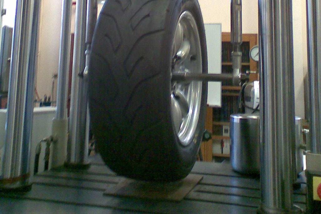
88 TOOLS FOR ASSESSING PERFORMANCE Tyre pressure gauge Tyre pyrometer (or infra red imaging camera) Stopwatch Data logger (Video Vbox Lite) Sensible and consistent driver with excellent feedback Video camera
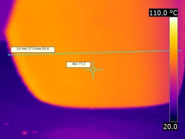
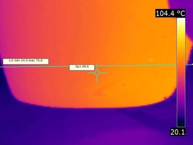
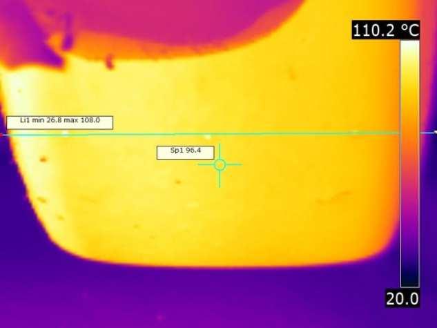
89 TUNING FOR HANDLING Reminder of the VEHICLE DYNAMICS MODEL STABILITY BALANCE VEHICLE DYNAMICS RESPONSE GRIP
90 TYRE CHARACTERISTICS Pressure (typically between 25psi 34psi hot) Around 60% of a tyres stiffness is due to the pressure Less = more GRIP, but less RESPONSE More = inverse of above Insufficient = damage to tyre side wall, risk of pulling tyre off the rim Excessive = tyre slides easily Use tyre temperature profile to determine: Edges high temperature = low pressure Centre high temperature = high pressure
91 TYRE TEMPERATURE
92 TYRE CHARACTERISTICS Camber (typically between -1.5 and -5.0 static) More = more lateral RESPONSE, more lateral GRIP Less = better straight line GRIP Insufficient = tyre wears outside edge Excessive = tyre slides easily, tyre wears inside edge Use tyre temperature profile to determine: Outer edges high temperature = low camber Inner edges high temperature = high camber Should accept inside edge to run approximately 15 hotter than outside edge
93 TYRE TEMPERATURE
94 TYRE CHARACTERISTICS Vertical load Tyre is sensitive to vertical load More load gives more tractive capacity The returns are diminishing A pair of tyres working in unison achieve their best grip when their load is equally distributed The softer end of a car transfers less load and has a more equal load distribution On the same given tyre, a lighter car will have better performance so long as optimum temperature is achieved (consider racing categories that use performance ballast)

95 TRACTIVE CAPACITY 300kg 250kg 300kg 250kg L=R= 250kg TOTAL GRIP = L + R = = 500kg L=R= 300kg VERTICAL FORCE

96 TRACTIVE CAPACITY 50kg transferred 250kg 210kg 350kg 280kg R= 280kg 250kg L= 210kg TOTAL GRIP = L + R = = 490kg LESS THAN 500kg! 250kg 300kg 350kg VERTICAL FORCE

97 WHEEL ALIGNMENT Load Transfer is related to h/t Centre of Gravity Height h Track Width t
98 TYRE CHARACTERISTICS Vertical load Feel of the car: BALANCE Understeer/Oversteer Use tyre temperatures to determine: Front tyres are hotter than rears = more front mass stiffer front springs, dampers or ARBs higher roll-centre more front brake bias FWD Rear tyres are hotter = inverse of above


99 TYRE TEMPERATURE AVERAGE = 74.7⁰C AVERAGE = 79.5⁰C AVERAGE = 75.5⁰C AVERAGE = 81.2⁰C

100
101 TYRE CHARACTERISTICS Temperature typically 85 to 120 C in the pit lane depending on compound Low temperature = less GRIP, poor tyre wear More temperature = more GRIP, better tyre wear, but faster Insufficient = cold graining (irreversible bad wear) Excessive = Excessive wear A cold tyre will feel skatey and inconsistent in grip A hot tyre will feel mushy and tired Use wear pattern and tyre temps to determine
102 TUNING FOR HANDLING Determine what you can change on your car: Toe Camber Ride heights (including rake) Corner weights ARB settings Damper settings What else Learn how to do these before you head to the track to not lose time
103 TUNING FOR HANDLING Next: How much time do you have?! 10 minutes? 2 hours? 1 day? 2 weeks?
104 TUNING FOR HANDLING Then ask: BALANCE STABILITY VEHICLE DYNAMICS GRIP RESPONSE Braking STABILITY? Mid-corner STABILITY? High-speed STABILITY? To improve STABILITY: - Increase rear TOE-IN - (BALANCE Understeer) - Stiffen DAMPERS - (RESPONSE Faster) - (GRIP will change) - Reduce CAMBER - (BALANCE, RESPONSE, GRIP)
105 TUNING FOR HANDLING Then ask: BALANCE STABILITY VEHICLE DYNAMICS GRIP RESPONSE Turn-in RESPONSE? Change of direction? Throttle-lift RESPONSE? To improve RESPONSE: - Increase front TOE-OUT - (BALANCE Oversteer) - Stiffen DAMPERS - (RESPONSE Faster) - (GRIP will change) - Increase CAMBER - (BALANCE, RESPONSE, GRIP)
106 TUNING FOR HANDLING Then ask: BALANCE STABILITY VEHICLE DYNAMICS GRIP RESPONSE Corner Entry BALANCE? Mid-corner BALANCE? Corner Exit BALANCE? To shift BALANCE forward: - Increase front TOE-OUT - (RESPONSE Faster) - Increase front CAMBER - (RESPONSE Faster) - (GRIP will change) - Soften front ARB - (RESPONSE Slower)
107 TUNING FOR HANDLING Then ask: BALANCE STABILITY VEHICLE DYNAMICS GRIP RESPONSE Braking GRIP? Mid-corner GRIP? Traction on corner exit? To increase GRIP: - Determine optimum tyre PRESSURE - Calculate optimum SPRING RATE - Calculate optimum DAMPER RATE - Test for optimum CAMBER
108 SETUP CHANGE DIFFICULTY SENSITIVITY RATIO Tyre Pressure Damper Click ARB Setting Damper Change Spring Change Ride height/rake Static Toe Static Camber Corner Weights Caster Bump-steer Camber Gain Roll Centre Height Anti-dive/ Anti-squat
109 Toe Front: TUNING FOR HANDLING More toe-out can balance front camber setting (more toeout for more camber) More toe out gives better turn-in Rear: More toe-in gives better stability (understeer) Less toe-in can reduce understeer Too much toe can cause excessive tyre edge wear and excessive tyre edge temperature
110 TUNING FOR HANDLING Static Camber Keep trying for more until: Tyre inner edge is too hot (more than 20 hotter than outer) Tyre inner edge wear is significant Remember to reduce tyre hot pressure to suit: try 1psi (hot)/degree of camber Front: More camber gives better turn-in, better RESPONSE More camber gives better GRIP Rear: Match with front camber (typically keep rear static camber around 0.5 less than front) Too much camber can cause excessive tyre edge wear and excessive tyre edge temperature
111 TUNING FOR HANDLING Damper Settings Overall Rebound only Bump only Low Speed High Speed Gas Pressure
112 TUNING FOR HANDLING Damper Settings OVERALL damping means adjusting bump and rebound together (your dampers may only have one adjuster, so check with the dyno graphs or damper builder which characteristic the adjuster varies) Need to have the OVERALL damping correct for the spring and mass combination If a car heaves, rolls and pitches, feeling almost like a boat, you can increase OVERALL damping to make the car more responsive and better held If a car feels firm and feels like it is skating on the surface, reduce the OVERALL damping
113 TUNING FOR HANDLING Damper Settings Once you find a good overall setting, you can adjust BUMP and REBOUND separately. CAUTION, if you, say, increase BUMP stiffness, you should reduce REBOUND stiffness, otherwise the car will become overdamped You would then misinterpret an OVERALL damping change for a BUMP change Ideally, look at your damper curves and determine how much one-click does in BUMP and REBOUND Otherwise, start with one-click BUMP for one-click REBOUND
114 TUNING FOR HANDLING Damper Settings Increasing REBOUND (and reducing BUMP to match overall) Better chassis control (STABILITY) Better feel (STABILITY, RESPONSE, BALANCE) Reduced mechanical (tyre) GRIP Increase aero GRIP (better control of the under floor orientation relative to the ground)
115 TUNING FOR HANDLING Damper Settings Increasing BUMP (and reducing REBOUND to match overall) Increases tyre temperature (maybe more GRIP) Increased mechanical (tyre) GRIP (better unsprung wheel control) Better wheel control over curbs and bumps (up to a limit, after that the ride can become too harsh)
116 TUNING FOR HANDLING Damper Settings Low Speed BUMP (LSB) is for unsprung wheel control on normal road surfaces and for body control More LSB gives more control Excessive LSB gives harsh ride High Speed BUMP (HSB) is for unsprung wheel control on curbs, bumps and dips Excessive HSB causes bump loads to be transmitted to the chassis (harsh) Insufficient HSB causes damper to compress too far hitting the bump stops or chassis touching the ground
117 TUNING FOR HANDLING Damper Settings Gas pressure is used to give the damper increased force range (by mitigating cavitation through the piston) Gas pressure can be used for tuning More gas pressure takes less load from spring causing: Increased ride height (may need to adjust) Reduce spring compression (less stored energy in the spring good thing) Excessive pressure = a harsh ride (need to reduce some OVERALL damping or reduce spring rate) Insufficient pressure = hitting bump stops, chassis motion uncontrolled
118 RACE ENGINEERING ACADEMY VEHICLE HANDLING BASICS PART 3: DIFFERENTIALS BY Dejan Ninic BE (Mech) PhD ENVIRAGE


119 DISTANCE TRAVELLED BY OUTER REAR WHEEL DISTANCE TRAVELLED BY INNER REAR WHEEL Distance travelled by outer wheel is GREATER than distance travelled by inner wheel Outer drive shaft must complete MORE revolutions than inner drive shaft to negotiate the turn
120 WITHOUT A DIFFERENTIAL To negotiate a left-hand turn, without a differential, the right-hand wheel forces the lefthand wheel to slip. This will force the car to drive straight, rather than steer (understeer).
121 WITH A DIFFERENTIAL With a differential, the right-hand wheel and the left-hand wheel can turn independently during a turn. This will allow the car to turn, but may also cause it to turn excessively (oversteer). AIM 1: Transmit engine torque to the driven wheels. AIM 2: Allow independent rotation of the driven wheels during turning.
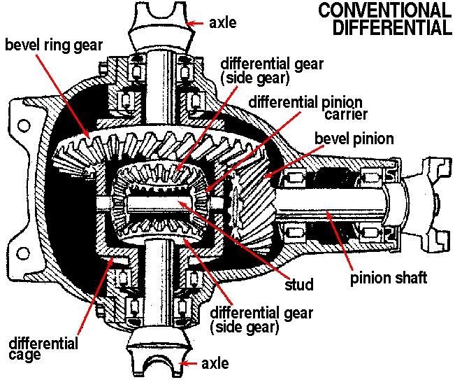
122 OPEN DIFFERENTIAL
123 OPEN DIFFERENTIAL SIDE GEARS TURNED BY PINIONS TOP VIEW SIDE VIEW
124 TORQUE DISTRIBUTION INPUT TORQUE = T LEFT SIDE OUTPUT TORQUE = L RIGHT SIDE OUTPUT TORQUE = R L = R = ½ T (EQUAL TORQUE DISTRIBUTION)
125 TYRES HAVE EQUAL GRIP T L R L = R = ½ T (EQUAL TORQUE DISTRIBUTION)
126 LEFT TYRE HAS LITTLE GRIP LEFT WHEEL SPINS AND CAR STANDS STILL 0 = 0 = 0 (NO TORQUE DISTRIBUTION)
127 SPEED OF ROTATION INPUT SPEED = NI LEFT SIDE OUTPUT SPEED = NL RIGHT SIDE OUTPUT SPEED = NR NI = ½ (NL + NR) NL = 2 NI - NR
128 SPEED OF ROTATION INPUT SPEED = NI LEFT SIDE OUTPUT SPEED = NL RIGHT SIDE OUTPUT SPEED = NR IF NR = 0? NL = 2 NI LEFT OUTPUT ROTATES TWICE AS FAST AS INPUT SPEED
129 SPEED OF ROTATION INPUT SPEED = NI LEFT SIDE OUTPUT SPEED = NL RIGHT SIDE OUTPUT SPEED = NR IF NI = 0? NL = - NR LEFT SIDE OUTPUT ROTATES OPPOSITE TO RIGHT SIDE
130 LEFT RIGHT TORQUE BALANCE T TORQUE BIAS = 1.0 L R L = R = ½ T (EQUAL TORQUE DISTRIBUTION)
131 SLIPPERY SITUATION ZERO THRUST TO MAKE CAR GO? ADD FRICTION! ZERO FRICTION ZERO TORQUE RESISTANCE ZERO TORQUE BALANCE
132 SLIPPERY SITUATION ENGINE CAN SUPPLY 200 UNITS OF TORQUE UNITS OF RESISTANCE = 100 UNITS TORQUE BALANCE
133 SLIPPERY SITUATION CAR MOVES FORWARD BUT, ALSO TURNS TO THE LEFT, EVEN IF THE STEERING IS HELD STRAIGHT! ENGINE REVS STILL RISE AS LEFT WHEEL IS SPINNING, BUT TORQUE CAN BE DELIVERED TO THE DIFFERENTIAL 100 UNITS OF RESISTANCE WILL REDUCE WHEEL SPIN BUT DO NOT PRODUCE FORWARD THRUST AS WHEEL IS SPINNING 100 UNITS OF TORQUE TRANSFERED PRODUCE FORWARD THRUST

134 SLIPPERY SITUATION THE MORE THE CAR MOVES FORWARD THE MORE THE CAR TURNS TO THE LEFT THE MORE TORQUE THE ENGINE CAN DELIVER THE MORE RESISTANCE WE ADD THE MORE TORQUE THAT IS TRANSFERED
135 LIMITED SLIP DIFFERENTIAL Almost all Limited Slip Differentials apply friction to eliminate excessive wheel spin Friction can be Constant (clutch pack, or cone) Linear (ramps and clutch pack : Hewland, ZF) Linear (geared: TorSen, hypoid) Progressive (viscous) Active (hydraulic piston and clutch pack, solenoid and clutch pack) Magnetic/Electric
136 LIMITED SLIP DIFFERENTIAL Some Limited Slip Differentials can lock completely Locking differentials include: Detroit Locker Cam and Pawl
137 LIMITED SLIP DIFFERENTIAL
138 OPEN DIFFERENTIAL TOP VIEW SIDE VIEW
139 CLUTCH PACK LSD TO ADD MORE PRELOAD WE CAN: STIFFEN THE SPRINGS, OR ADD MORE PLATES
140 CLUTCH PACK LSD ADDING MORE PRELOAD PRODUCES: MORE RESISTANCE MORE TORQUE TRANSFER MORE THRUST BUT ALSO MORE TENDENCY FOR THE CAR TO TURN
141 RAMP AND CLUTCH PACK LSD INPUT TORQUE FORCES RAMPS APART MORE FRICTION IS GENERATED TOP VIEW SIDE VIEW
142 RAMP AND CLUTCH PACK LSD THE GREATER THE TORQUE INPUT THE GREATER THE RAMP SEPARATION THE GREATER THE FRICTION THE GREATER THE THRUST BUT ALSO, THE GREATER THE TENDENCY TO TURN
143 RAMP AND CLUTCH PACK LSD RAMPS ARE TYPICALLY TAPERED BETWEEN 25 AND 90 A 25 RAMP PRODUCES MORE FRICTION THAN A 80 RAMP FOR THE SAME INPUT TORQUE A 90 RAMP WILL NOT CAUSE THE RAMPS TO SEPARATE
144 RAMP AND CLUTCH PACK LSD UNDER BRAKING THE OVER- RUN SIDE OF THE RAMPS OPERATE THE INPUT TORQUE IS NOTA FUNCTION OF HOW HARD THE BRAKES ARE APPLIED THE INPUT TORQUE IS A FUNCTION OF HOW MUCH ENGINE BRAKING IS USED
145 RAMP AND CLUTCH PACK LSD ACCELERATION RAMPS ARE TYPICALLY BETWEEN 25 AND 60 OVER-RUN RAMPS ARE TYPICALLY BETWEEN 60 AND 90
146 RAMP AND CLUTCH PACK LSD THIS DIFFERENTIAL CAN BECOME COMPLETELY LOCKED IF: RAMP ANGLES ARE TOO SHALLOW TOO MANY PLATES ARE USED TOO MUCH PRELOAD, OR ANY COMBINATION OF THE THREE
147 RAMP AND CLUTCH Can tune the amount of resistance to give Better traction Better corner-exit turning Greater braking stability Greater mid-corner, dropped throttle, stability Can tune using ADVANTAGES Preload Ramp Angles Number of Plates, and Type of Oil
148 RAMP AND CLUTCH DISADVANTAGES Internal friction Generates heat (and may need cooling) Increases fuel and tyre consumption Varies with temperature Requires regular servicing if used for racing Neglecting to service results in Increased wear Inconsistent behaviour Permanent damage to ramps and plates Complete rupture
149 Internal gearing Allows wheels to turn at independent speeds while still delivering equivalent torque Resists inside wheel from spinning when the resistance reduces to zero Multiplies the torque available on the inside wheel to the outside wheel (torque biasing) Torque Biasing Is typically in the order of 1.5 up to 4 times Depends on gearing Is not easily tuned TORSEN DIFFERENTIAL
150 TORSEN DIFFERENTIAL ENGINE CAN DELIVER TORQUE TO THRUST CAR ASSUME A TORQUE BIAS OF 3:1 ALMOST ZERO WHEEL SPIN! ASSUME ONLY 10 UNITS OF FRICTION AVAILABLE 30 UNITS OF FRICTION TRANSFERRED TO RIGHT SIDE
151 TORSEN DIFFERENTIAL ENGINE CAN NOT DELIVER TORQUE TO THRUST CAR ASSUME A TORQUE BIAS OF 3:1 ZERO UNITS OF FRICTION AVAILABLE 0 UNITS OF FRICTION TRANSFERRED TO RIGHT SIDE CAR STANDS STILL!
152 TORSEN ADVANTAGES Improved traction in slippery conditions compared to open differential Smooth biasing of torque Internal friction occurs only when gears are biasing torque so does not consume fuel during normal driving Excellent operation in very low grip situations (ice) as biasing is not excessive
153 TORSEN DISADVANTAGES Heavy Torque bias reduces as gears start to wear Need to change all of the gears to change the torque bias Expensive (although equivalent copies are becoming cheaper by the day)
154 LOCKED DIFFERENTIAL Typically called a spool differential Solid link between driven wheels Wheels are forced to move at the same speed Can be useful for applications in racing cars with high power Has been used successfully in racing (gokarts, Porsche , ) Most ramp and clutch differentials become fully locked under partial or full throttle applications
155 LOCKED ADVANTAGES Cheap Easy Consistent behaviour Reliable Excellent traction on corner exit
156 LOCKED DISADVANTAGES Difficult to manoeuvre car at slow speed Difficult to turn car into a corner Can bind up and release causing car to spin off the road Increases tyre wear as inside wheel is caused to slip
157 INFLUENCE ON HANDLING INPUT TORQUE LOW TORQUE HIGH TORQUE DIFF. FUNCTION LIMITING SLIP TORQUE MULTIPLYING LOCKED TRACTIVE CAPACITY HIGH GRIP NO WHEELSPIN MEDIUM GRIP INSIDE WHEEL SPIN LOW GRIP BOTH SPIN VEHICLE DYNAMICS DRIVE TRACTION UNDERSTEER OVERSTEER
158 WHICH IS BEST? Low power road car Medium power road car High power road car Open or TorSen TorSen or Clutch pack TorSen or Ramp and clutch pack Medium power circuit racing car Ramp and clutch pack High power circuit racing car Ramp and clutch pack, Locked High power circuit car with wings Locked Medium power gravel rally car High power gravel rally car TorSen or Ramp and clutch pack Ramp and clutch pack
Torque steer effects resulting from tyre aligning torque Effect of kinematics and elastokinematics
 P refa c e Tyres of suspension and drive 1.1 General characteristics of wheel suspensions 1.2 Independent wheel suspensions- general 1.2.1 Requirements 1.2.2 Double wishbone suspensions 1.2.3 McPherson
iracing.com Williams-Toyota FW31 Quick Car Setup Guide
 iracing.com Williams-Toyota FW31 Quick Car Setup Guide In this guide we will briefly explain a number of key setup parameters which are distinct to the FW31 and which are new to iracing vehicles. We hope
Part 1. The three levels to understanding how to achieve maximize traction.
 Notes for the 2017 Prepare to Win Seminar Part 1. The three levels to understanding how to achieve maximize traction. Level 1 Understanding Weight Transfer and Tire Efficiency Principle #1 Total weight
ROLL CENTER You can adjust the front and rear roll centers of the XB8 by changing the mounting locations of various components.
 Your XRAY XB8 luxury nitro buggy is a top competition, precision racing machine that features multiple adjustments that allow you to set up for any track condition. The XB8 includes innovative set-up features
A double-wishbone type suspension is used in the front. A multi-link type suspension is used in the rear. Tread* mm (in.) 1560 (61.
 1560 (61.") CHASSIS SUSPENSION AND AXLE CH-69 SUSPENSION AND AXLE SUSPENSION 1. General A double-wishbone type suspension is used in the front. A multi-link type suspension is used in the rear. 08D0CH111Z Specifications
CHASSIS SUSPENSION AND AXLE CH-69 SUSPENSION AND AXLE SUSPENSION 1. General A double-wishbone type suspension is used in the front. A multi-link type suspension is used in the rear. 08D0CH111Z Specifications
TIPS TO FINAL ASSEMBLY Radio installation. The Electronic speed control (ESC) and the receiver need to be mounted onto the chassis, using double sided
 and the receiver need to be mounted onto the chassis, using double sided") TIPS TO FINAL ASSEMBLY Radio installation. The Electronic speed control (ESC) and the receiver need to be mounted onto the chassis, using double sided tape (not supplied.) Mount the ESC first on the chassis
TIPS TO FINAL ASSEMBLY Radio installation. The Electronic speed control (ESC) and the receiver need to be mounted onto the chassis, using double sided tape (not supplied.) Mount the ESC first on the chassis
SUMMARY OF STANDARD K&C TESTS AND REPORTED RESULTS
 Description of K&C Tests SUMMARY OF STANDARD K&C TESTS AND REPORTED RESULTS The Morse Measurements K&C test facility is the first of its kind to be independently operated and made publicly available in
Design and Integration of Suspension, Brake and Steering Systems for a Formula SAE Race Car
 Design and Integration of Suspension, Brake and Steering Systems for a Formula SAE Race Car Mark Holveck 01, Rodolphe Poussot 00, Harris Yong 00 Final Report May 5, 2000 MAE 340/440 Advisor: Prof. S. Bogdonoff
X4-X7 Hyper 600cc Chassis Setup Guide
 Suggested Starting Setup on a Normal Condition 1/6 or 1/8 Mile Track, Winged Left Front Right Front Left Rear Right Rear Torsion Bar Size (+ Turns).675 (+0).675 (+0).725 (+0).750 (+1) Coil Size (+ Turns)
Design and Analysis of suspension system components
 Design and Analysis of suspension system components Manohar Gade 1, Rayees Shaikh 2, Deepak Bijamwar 3, Shubham Jambale 4, Vikram Kulkarni 5 1 Student, Department of Mechanical Engineering, D Y Patil college
ON ROAD SETUP GUIDE PART ONE
 PART ONE Ride height is adjusted by the preload of the spring collars. Winding them down will raise the ride height, while winding them up will decrease the ride height. It is important to note that adjusting
SPMM OUTLINE SPECIFICATION - SP20016 issue 2 WHAT IS THE SPMM 5000?
 SPMM 5000 OUTLINE SPECIFICATION - SP20016 issue 2 WHAT IS THE SPMM 5000? The Suspension Parameter Measuring Machine (SPMM) is designed to measure the quasi-static suspension characteristics that are important
Improves Traction and Lateral G s
 Tuesday, February 14, 2012 New Product Release: Griggs/VariShock Improves Traction and Lateral G s Double-Adjustable Ultra-Light Coil-Over Shock Absorbers Available NOW!! Can be used on any high performance
SPMM OUTLINE SPECIFICATION - SP20016 issue 2 WHAT IS THE SPMM 5000?
 SPMM 5000 OUTLINE SPECIFICATION - SP20016 issue 2 WHAT IS THE SPMM 5000? The Suspension Parameter Measuring Machine (SPMM) is designed to measure the quasi-static suspension characteristics that are important
Technical Report Lotus Elan Rear Suspension The Effect of Halfshaft Rubber Couplings. T. L. Duell. Prepared for The Elan Factory.
 Technical Report - 9 Lotus Elan Rear Suspension The Effect of Halfshaft Rubber Couplings by T. L. Duell Prepared for The Elan Factory May 24 Terry Duell consulting 19 Rylandes Drive, Gladstone Park Victoria
Fundamentals of Steering Systems ME5670
 Fundamentals of Steering Systems ME5670 Class timing Monday: 14:30 Hrs 16:00 Hrs Thursday: 16:30 Hrs 17:30 Hrs Lecture 3 Thomas Gillespie, Fundamentals of Vehicle Dynamics, SAE, 1992. http://www.me.utexas.edu/~longoria/vsdc/clog.html
2005 to 2008 #08 Metric Nova Chassis Set Up Sheet
 Springs 1 2005 to 2008 #08 Metric Nova Chassis Set Up Sheet Flat end of spring down on tubular lower a-arms. Left Front 800lb. Right Front 750lb. Left Rear 200lb. Right Rear 225lb. On Top of Tube Axle
Suspension systems and components
 Suspension systems and components 2of 42 Objectives To provide good ride and handling performance vertical compliance providing chassis isolation ensuring that the wheels follow the road profile very little
I. Tire Heat Generation and Transfer:
 Caleb Holloway - Owner calebh@izzeracing.com +1 (443) 765 7685 I. Tire Heat Generation and Transfer: It is important to first understand how heat is generated within a tire and how that heat is transferred
Designing and Hard Point Optimization of Suspension System of a Three-Wheel Hybrid Vehicle
 ISSN (O): 2393-8609 International Journal of Aerospace and Mechanical Engineering Designing and Hard Point Optimization of Suspension System of a Three-Wheel Hybrid Vehicle Gomish Chawla B.Tech Automotive
KINEMATICS OF REAR SUSPENSION SYSTEM FOR A BAJA ALL-TERRAIN VEHICLE.
 International Journal of Mechanical Engineering and Technology (IJMET) Volume 8, Issue 8, August 2017, pp. 164 171, Article ID: IJMET_08_08_019 Available online at http://www.iaeme.com/ijmet/issues.asp?jtype=ijmet&vtype=8&itype=8
Tech Tip: Trackside Tire Data
 Using Tire Data On Track Tires are complex and vitally important parts of a race car. The way that they behave depends on a number of parameters, and also on the interaction between these parameters. To
Cane Creek Double Barrel Instructions
 Cane Creek Double Barrel Instructions Congratulations on your purchase of the Cane Creek Double Barrel rear shock. Developed in partnership with Öhlins Racing, the Double Barrel brings revolutionary suspension
Unit HV04K Knowledge of Heavy Vehicle Chassis Units and Components
 Assessment Requirements Unit HV04K Knowledge of Heavy Vehicle Chassis Units and Components Content: Chassis layouts i. types of chassis ii. axle configurations iii. rear steered axles iv. self-steered
August 2001 THINGS THAT MAKE SPRING CHANGES WORK BACKWARDS
 August 2001 WELCOME Mark Ortiz Automotive is a chassis consulting service primarily serving oval track and road racers. This newsletter is a free service intended to benefit racers and enthusiasts by offering
PRESEASON CHASSIS SETUP TIPS
 PRESEASON CHASSIS SETUP TIPS A Setup To-Do List to Get You Started By Bob Bolles, Circle Track Magazine When we recently set up our Project Modified for our first race, we followed a simple list of to-do
Discussion Paper. Effect of Anti-Squat Adjustment in Solid Axle 4 Link Rear Suspension Systems
 Discussion Paper Effect of Anti-Squat Adjustment in Solid Axle 4 Link Rear Suspension Systems Example used is Commodore 1990 VG utility fitted with Whiteline KTA103 adjustable upper trailing arms. Prepared
Basic Wheel Alignment Techniques
 Basic Wheel Alignment Techniques MASTERING THE BASICS: Modern steering and suspension systems are great examples of solid geometry at work. Wheel alignment integrates all the factors of steering and suspension
3.0 Tuning Tips. To Shut Off the Engine: Use the included pipe plug or simply bump the flywheel with a wrench or plastic handled tool.
 TM 8IGHT 3.0 Tuning Tips Before you start making changes on your 8IGHT 3.0 Off-Road Racing buggy, you need to make a few decisions. First of all, tires, and how they are setup, have a tremendous impact
CHASSIS DYNAMICS TABLE OF CONTENTS A. DRIVER / CREW CHIEF COMMUNICATION I. CREW CHIEF COMMUNICATION RESPONSIBILITIES
 CHASSIS DYNAMICS TABLE OF CONTENTS A. Driver / Crew Chief Communication... 1 B. Breaking Down the Corner... 3 C. Making the Most of the Corner Breakdown Feedback... 4 D. Common Feedback Traps... 4 E. Adjustment
General Vehicle Information
 Vehicle #3921 Chevrolet Equinox (2CNALBEW8A6XXXXXX) Inspection Date: 1-Feb-211 Year 21 Make Model Body Style HVE Display Name: Year Range: Sisters and Clones: Vehicle Category: Vehicle Class: VIN: Date
Appendix X New Features in v2.4 B
 Appendix X New Features in v2.4 B Version 2.4B adds several features, which we have grouped into these categories: New Suspension Types or Options The program now allows for solid front axles and for several
Data acquisition and analysis tools
 Workshop Goals Introduce Data acquisition tools and Laptime simulation tools Show what to look for in logged data and what to focus on. Discuss the appropriate use of racecar simulation tools. Present
WHY CHOOSE MOTOR TRIKE INDEPENDENT REAR SUSPENSION?
 WHY CHOOSE MOTOR TRIKE INDEPENDENT REAR SUSPENSION? WHY CHOOSE MOTOR TRIKE INDEPENDENT REAR SUSPENSION? NOT ALL INDEPENDENT REAR SUSPENSIONS (IRS) ARE CREATED EQUALLY. THIS IS WHY A BMW AND A HYUNDAI DON
CONTENTS. All texts and images contained within this set-up book are copyright by XRAY. All rights reserved. XRAY
 CONTENTS Setting up the XRAY T3 3 Downstops 6 Ride Height 8 Droop 10 Track Width 12 Steering Throw Symmetry 13 Camber 14 Caster 16 Bump Steer 17 Ackermann 17 Toe 18 Tweak 20 Roll Center 24 Chassis Flex
STUDY OF ROLL CENTER SAURABH SINGH *, SAGAR SAHU ** ABSTRACT
 STUDY OF ROLL CENTER SAURABH SINGH *, SAGAR SAHU ** *, ** Mechanical engineering, NIT B ABSTRACT As our solar car aims to bring new green technology to cope up with the greatest challenge of modern era
The Mark Ortiz Automotive
 July 2004 WELCOME Mark Ortiz Automotive is a chassis consulting service primarily serving oval track and road racers. This newsletter is a free service intended to benefit racers and enthusiasts by offering
Welcome and enjoy tuning your Manitou ABS+ Compression Damping System! Purposefully engineered to raise your expectations.
 Welcome and enjoy tuning your Manitou ABS+ Compression Damping System! Purposefully engineered to raise your expectations. PLEASE READ SERVICE INSTRUCTIONS PRIOR TO BEGINNING WORK. While revalving your
Wheel Alignment Defined
 Wheel Alignment Defined While it's often referred to simply as an "alignment" or "wheel alignment," it's really complex suspension angles that are being measured and a variety of suspension components
VariShock QuickSet 2 Coil-Over Installation and Tuning Guide
 VariShock QuickSet 2 Coil-Over Installation and Tuning Guide Part Number Qty. Description Various 2 Coil-Over Shock with Threaded Body (pair) 899-002-200 2 Lower Coil-Over Spring Seat 899-002-201 2 Upper
B.TECH III Year I Semester (R09) Regular & Supplementary Examinations November 2012 DYNAMICS OF MACHINERY
 Regular & Supplementary Examinations November 2012 DYNAMICS OF MACHINERY") 1 B.TECH III Year I Semester (R09) Regular & Supplementary Examinations November 2012 DYNAMICS OF MACHINERY (Mechanical Engineering) Time: 3 hours Max. Marks: 70 Answer any FIVE questions All questions
1 B.TECH III Year I Semester (R09) Regular & Supplementary Examinations November 2012 DYNAMICS OF MACHINERY (Mechanical Engineering) Time: 3 hours Max. Marks: 70 Answer any FIVE questions All questions
OTK CHASSIS- SET UP GUIDE
 OTK CHASSIS- SET UP GUIDE Introduction This setup guide is created to facilitate a user of OTK equipment to reach an optimal chassis setup and on-track performance. The different tuning possibilities and
Roehrig Engineering, Inc.
 Roehrig Engineering, Inc. Home Contact Us Roehrig News New Products Products Software Downloads Technical Info Forums What Is a Shock Dynamometer? by Paul Haney, Sept. 9, 2004 Racers are beginning to realize
Motorcycle Suspension, How They Work, Install and Set Up
 Motorcycle Suspension, How They Work, Install and Set Up Presenters: Klaus Huenecke and Duane Kerzic of Wilbers USA Time: Place: Audience: Beginner to Advanced Street Riders who want to know more about
VEHICLE DYNAMICS. A factsheet on Volvo Cars Scalable Product Architecture chassis technology
 VEHICLE DYNAMICS A factsheet on Volvo Cars Scalable Product Architecture chassis technology VEHICLE DYNAMICS Contents Driving Confidence 3 Chassis Simulation 4 - Connecting objective testing to human experience
Torsen Differentials - How They Work and What STaSIS Does to Improve Them For the Audi Quattro
 Torsen Differentials - How They Work and What STaSIS Does to Improve Them For the Audi Quattro One of the best bang-for-your buck products that STaSIS has developed is the center differential torque bias
ASSOCIATED 1:10 SCALE ELECTRIC BUGGY INSTRUCTION MANUAL FOR THE TEAM ASSOCIATED RC10B Associated Electrics, Inc. RS-1
 ASSOCIATED 1:10 SCALE ELECTRIC BUGGY INSTRUCTION MANUAL FOR THE TEAM ASSOCIATED RC10B4 TT RS-1 2003-2006 Associated Electrics, Inc. FINAL ADJUSTMENTS RADIO ADJUSTMENTS Use the following
A new approach to steady state state and quasi steady steady state vehicle handling analysis
 Vehicle Dynamics Expo June 16 nd -18 th 2009 A new approach to steady state state and quasi steady steady state vehicle handling analysis Presentation By Claude Rouelle OptimumG Overview Vehicle Dynamics
BIG BAR SOFT SPRING SET UP SECRETS
 BIG BAR SOFT SPRING SET UP SECRETS Should you be jumping into the latest soft set up craze for late model asphalt cars? Maybe you will find more speed or maybe you won t, but either way understanding the
Pan Car Setup and Troubleshooting
 Pan Car Setup and Troubleshooting Problems can come up in the midst of competition. Either the car is not handling properly on the track or there are problems with equipment. Troubleshooting problems should
Brake, suspension and side slip testers... the facts! October 2009 Technical Newsletter
 October 2009 Technical Newsletter Brake, suspension and side slip testers... the facts! VTEQ brake test lane at Jim Wright Nissan AECS Ltd is the NZ distributor of the VTEQ test equipment since 2001. AECS
III B.Tech I Semester Supplementary Examinations, May/June
 Set No. 1 III B.Tech I Semester Supplementary Examinations, May/June - 2015 1 a) Derive the expression for Gyroscopic Couple? b) A disc with radius of gyration of 60mm and a mass of 4kg is mounted centrally
SHOCK DYNAMOMETER: WHERE THE GRAPHS COME FROM
 SHOCK DYNAMOMETER: WHERE THE GRAPHS COME FROM Dampers are the hot race car component of the 90s. The two racing topics that were hot in the 80s, suspension geometry and data acquisition, have been absorbed
Suspension Analyzer Full Vehicle Version
 Suspension Analyzer Full Vehicle Version Overview of Features The Full Vehicle version of Suspension Analyzer has several enhancements over the standard version, the most significant is analyzing various
Jim Kasprzak 36 years racing experience Developed 7-post testing for GM Racing Currently Race Engineer for SRT Viper Expertise includes:
 Jim Kasprzak 36 years racing experience Developed 7-post testing for GM Racing Currently Race Engineer for SRT Viper Expertise includes: Race Engineering 7 post testing Suspension Engineering Shock design,
Increase performance of all-terrain vehicle by tuning of various components
 Increase performance of all-terrain vehicle by tuning of various components Bhavdeep Trivedi Marut Patel Deep Patel Ripen Shah Asst. Professor, Mechanical Department, Silver Oak College of Engg. & Tech.,
PS-8300-DA Shock, Double-Adjustable Remote & Piggyback TECHNICAL MANUAL
 PS-8300-DA Shock, Double-Adjustable Remote & Piggyback TECHNICAL MANUAL Main Office 150 Franklin St. P.O. Box 1056 Reading, PA 19603 (610) 375-6180 (610) 375-6190 Fax Table of Contents: PS 8300RM/PB DOUBLE
1698 Midwest Blvd. Indianapolis, IN
 1698 Midwest Blvd. Indianapolis, IN 46214 317.271.7100 5500 Series Quarter Midget Shock The Advanced Racing Suspensions quarter midget shock continues to be the dominate shock in Quarter Midget Racing.
After Installing an Öhlins Shock Absorber/Front Fork
 Checkpoint Öhlins After Installing an Öhlins Shock Absorber/Front Fork Note! All motorcycles are designed with a suspension geometry that includes height and fork angle. Changing components (for example
R10 Set No: 1 ''' ' '' '' '' Code No: R31033
 R10 Set No: 1 III B.Tech. I Semester Regular and Supplementary Examinations, December - 2013 DYNAMICS OF MACHINERY (Common to Mechanical Engineering and Automobile Engineering) Time: 3 Hours Max Marks:
1. SPECIFICATIONS 2. WHEEL ALIGNMENT Front Suspension. (gas type) Rear Suspension. (gas type)
 Rear Suspension. (gas type)") 441101 053 1. SPECIFICATIONS Front Suspension Rear Suspension Description Suspension type Spring type Shock absorber type Stabilizer bar type Suspension type Spring type Shock absorber type Stabilizer
441101 053 1. SPECIFICATIONS Front Suspension Rear Suspension Description Suspension type Spring type Shock absorber type Stabilizer bar type Suspension type Spring type Shock absorber type Stabilizer
DESIGN AND ANALYSIS OF PUSH ROD ROCKER ARM SUSPENSION USING MONO SPRING
 Volume 114 No. 9 2017, 465-475 ISSN: 1311-8080 (printed version); ISSN: 1314-3395 (on-line version) url: http://www.ijpam.eu ijpam.eu DESIGN AND ANALYSIS OF PUSH ROD ROCKER ARM SUSPENSION USING MONO SPRING
The Mark Ortiz Automotive
 August 2004 WELCOME Mark Ortiz Automotive is a chassis consulting service primarily serving oval track and road racers. This newsletter is a free service intended to benefit racers and enthusiasts by offering
White Paper: The Physics of Braking Systems
 White Paper: The Physics of Braking Systems The Conservation of Energy The braking system exists to convert the energy of a vehicle in motion into thermal energy, more commonly referred to as heat. From
Shock Absorbers What is Ride Control Vehicle Dynamics Suspension System Shock Absorbers Struts Terminology
 Home Tech Support Shock Absorbers Shock Absorbers What is Ride Control Vehicle Dynamics Suspension System Shock Absorbers Struts Terminology A BRIEF HISTORY These first shock absorbers were simply two
Make these adjustments before racing
 FINAL ADJUSTMENTS ADJUSTING CAMBER To set the camber we recommend using our supplied #1719 camber/rear toe-in gauge. When adjusting camber you need to have the car ready to run with no body. Make these
Collegiate Design Series Suspension 101. Steve Lyman Formula SAE Lead Design Judge DaimlerChrysler Corporation
 Collegiate Design Series Suspension 101 Steve Lyman Formula SAE Lead Design Judge DaimlerChrysler Corporation There Are Many Solutions It depends. Everything is a compromise. Suspension 101 Ride Frequency/
1. SPECIFICATIONS 2. WHEEL ALIGNMENT
 441101 083 1. SPECIFICATIONS Front Suspension Rear Suspension Description Suspension type Spring type Shock absorber type Stabilizer bar type Suspension type Spring type Shock absorber type Stabilizer
QuickTrick Alignment Tools
 QuickTrick Alignment Tools QuickTrick Alignment Kits are Professional quality tools designed for a lifetime of reliable service. QuickTrick Kits can be used on any vehicle for measurement of the alignment
1 Summary PROPORTIONAL RESPONSE TECHNICAL SUMMARY. Contents
 HABIT WHITE PAPER PROPORTIONAL RESPONSE TECHNICAL SUMMARY Contents 1 Summary 1 2 Suspension for Mountain Bikes 2 3 Proportional Response 10 4 Experimental Validation of Suspension Response 12 5 Size Specific
ON Road comfort OFF Road control
 ON Road comfort OFF Road control Shock Absorbers Heavy Duty Coil Springs Leaf Springs Torsion Bars Air Bag Kits Bushes Brakes Skid Plates Straight advice, specialists you understand and... range overview
Design of Suspension and Steering system for an All-Terrain Vehicle and their Interdependence
 Design of Suspension and Steering system for an All-Terrain Vehicle and their Interdependence Saurabh Wanganekar 1, Chinmay Sapkale 2, Priyanka Chothe 3, Reshma Rohakale 4,Samadhan Bhosale 5 1 Student,Department
The g-force Family Control Manual
 This brochure has been developed to assist you in getting the most out of your tires during a given race or track session. This information is general in nature, and numerous variables such as track conditions,
MECHANICAL EQUIPMENT. Engineering. Theory & Practice. Vibration & Rubber Engineering Solutions
 MECHANICAL EQUIPMENT Engineering Theory & Practice Vibration & Rubber Engineering Solutions The characteristic of an anti-vibration mounting that mainly determines its efficiency as a device for storing
Quarter Midget Catalog
 Quarter Midget Catalog 317.271.7100 1698 Midwest Blvd, Indianapolis, IN 46214 www.advancedracing.net 5500 SERIES QUARTER MIDGET SHOCK The Advanced Racing Suspensions quarter midget shock continues to be
Assetto Corsa Car Modding Worksheet v0.16
 Assetto Corsa Car Modding Worksheet v0.16 by: Storm Rider http://www.behance.net/felipevaiano Special Thanks to Pankykapus Credits: Pankykapus, Andrea Lojelo, Avoletta, Stereo Bibliography: How to make
Wheel Alignment Fundamentals
 CHAPTER 67 Wheel Alignment Fundamentals OBJECTIVES Upon completion of this chapter, you should be able to: Describe each wheel alignment angle. Tell which alignment angles cause wear or pull. KEY TERMS
Multilink IRS Setup & Assembly Manual
 Art Morrison Enterprises Multilink IRS Setup & Assembly Manual 8/13/2018 Rev 6 Contents Introduction... 3 Toe Link Eccentric... 3 Powdercoating... 3 IRS Assembly Steps... 4 1. Backing plates/knuckles/hubs...
Vehicle dynamics Suspension effects on cornering
 Vehicle dynamics Suspension effects on cornering Pierre Duysinx LTAS Automotive Engineering University of Liege Academic Year 2013-2014 1 Bibliography T. Gillespie. «Fundamentals of vehicle Dynamics»,
Dynamic Analysis of Double Wishbone and Double Wishbone with S Link + Toe Link
 RESEARCH ARTICLE OPEN ACCESS Dynamic Analysis of Double Wishbone and Double Wishbone with S Link + Toe Link Rajkumar Kewat, Anil Kumar Kundu,Kuldeep Kumar,Rohit Lather, Mohit Tomar RJIT, B.S.F ACADEMY
Purposes of a Drive Axle Assembly
 Differentials Purposes of a Drive Axle Assembly To transmit power from the drive shaft to the wheels To turn the power flow 90 degrees on RWD cars To allow the wheels to turn at different speeds while
 www.whiteline.com.au ROCK ROLL CENTRE KIT ESSENTIAL FOR LOWERED VEHICLES Recommended for race use only WHITELINE diagnosed a mediocre MacPherson front suspension with poor roll centre control and excessive
Determination of anti pitch geometry. acceleration [1/3]
![Determination of anti pitch geometry. acceleration [1/3]](/thumbs/83/87345496.jpg "Determination of anti pitch geometry. acceleration [1/3]") 1of 39 Determination of anti pitch geometry Similar to anti squat Opposite direction of D Alembert s forces. acceleration [1/3] Front wheel forces and effective pivot locations 2of 39 Determination of
1of 39 Determination of anti pitch geometry Similar to anti squat Opposite direction of D Alembert s forces. acceleration [1/3] Front wheel forces and effective pivot locations 2of 39 Determination of
The g-force Family Control Manual
 This brochure has been developed to assist you in getting the most out of your tires during a given race or track session. This information is general in nature, and numerous variables such as track conditions,
II YEAR AUTOMOBILE ENGINEERING AT AUTOMOTIVE CHASSIS QUESTION BANK UNIT I - LAYOUT, FRAME, FRONT AXLE AND STEERING SYSTEM
 II YEAR AUTOMOBILE ENGINEERING AT 6402 - AUTOMOTIVE CHASSIS QUESTION BANK UNIT I - LAYOUT, FRAME, FRONT AXLE AND STEERING SYSTEM 1. Write about the requirements of frame and selection of cross section
Integrated damper suspension system
 Integrated damper suspension system Introduction Vehicle dynamics and damping Converting kinetic energy into Thermal energy Controllong extension stroke of the suspension Integrated suspension/damping
Appendix A: Motion Control Theory
 Appendix A: Motion Control Theory Objectives The objectives for this appendix are as follows: Learn about valve step response. Show examples and terminology related to valve and system damping. Gain an
ME 455 Lecture Ideas, Fall 2010
 ME 455 Lecture Ideas, Fall 2010 COURSE INTRODUCTION Course goal, design a vehicle (SAE Baja and Formula) Half lecture half project work Group and individual work, integrated Design - optimal solution subject
Shock Absorber for Renault Megane R.S. N4 TPX/TTX44 RER XL52. Owner s Manual
 Shock Absorber for Renault Megane R.S. N4 TPX/TTX44 RER XL5 Owner s Manual Öhlins Racing AB - The Story It was the 970 s, a young man named Kenth Öhlin spent most of his spare time pursuing his favourite
Handout Activity: HA487
 Tires HA487-2 Handout Activity: HA487 Tires Tires are mainly made from synthetic materials. They can be tubed or tubeless, with different types of construction, profile and speed ratings. The tire provides
Analysis and control of vehicle steering wheel angular vibrations
 Analysis and control of vehicle steering wheel angular vibrations T. LANDREAU - V. GILLET Auto Chassis International Chassis Engineering Department Summary : The steering wheel vibration is analyzed through
Every difficulty slurred over will be a ghost to disturb your repose later on. Frederic Chopin
 SUSPENSION DESIGN Every difficulty slurred over will be a ghost to disturb your repose later on. Frederic Chopin 16 Over 1500 hours were spent designing the chassis. Larry didn t want any modifications
TOO TECH RACING SET-UP INSTRUCTIONS (For Non Twin Chamber Showa & KYB)
") TOO TECH RACING SET-UP INSTRUCTIONS (For Non Twin Chamber Showa & KYB) STEP 1: Measure suspension "Race Sag". (Most important adjustment there is) First: Put the bike on a center stand and release the
TOO TECH RACING SET-UP INSTRUCTIONS (For Non Twin Chamber Showa & KYB) STEP 1: Measure suspension "Race Sag". (Most important adjustment there is) First: Put the bike on a center stand and release the
According to Newton's First Law, a moving body will continue moving in a straight line until it is acted
 RIDE CONTROL DEFINED According to Newton's First Law, a moving body will continue moving in a straight line until it is acted upon by another force. Newton's Second Law states that for each action there
Audi R8 LMS Cup Cup Car Technical Restrictions/Guidelines. PUBLISHED version 1.0: 11 May 2016.
 Audi R8 LMS Cup 2016 Cup Car Technical Restrictions/Guidelines PUBLISHED version 1.0: 11 May 2016. CONTENTS Specific Technical Restrictions and Guidelines.... 3 General Adjustments Information.... 3 TR1.
Front Coil-Over Conversion, QuickSet Camaro/Firebird Installation and Tuning Guide
 Front Coil-Over Conversion, QuickSet 1 1993-2003 Camaro/Firebird Installation and Tuning Guide VAS 8612F-834 Parts List Part Number Qty. Description 833-012-201 1 Spanner Wrench for 2.80 Diameter Spring
PYROMETER - General Notes on interpreting the Information
 As a general rule of thumb the following notes are an overview of what type of things to expect or look for in analysing the information that you record with the use of a pyrometer on tyre tread temperatures.
Driving dynamics GENERAL INFORMATION WINTER MODE. JaguarDrive Control
 GENERAL INFORMATION Driving dynamics It remains the driver's responsibility to drive safely, according to the prevailing conditions and within the law. JaguarDrive Control JaguarDrive Control is a selectable
Kinematic Analysis of Roll Motion for a Strut/SLA Suspension System Yung Chang Chen, Po Yi Tsai, I An Lai
 Kinematic Analysis of Roll Motion for a Strut/SLA Suspension System Yung Chang Chen, Po Yi Tsai, I An Lai Abstract The roll center is one of the key parameters for designing a suspension. Several driving
Tech Tip: Springs & Dampers, Part One The Phantom Knowledge
 Tech Tip: Springs & Dampers, Part One The Phantom Knowledge By Matt Giaraffa matt.giaraffa@optimumg.com When out on the track, you can spend an entire weekend tuning spring rates and shock settings, and