Installation, Operation and Maintenance Manual
|
|
|
- Barbara Newton
- 5 years ago
- Views:
Transcription
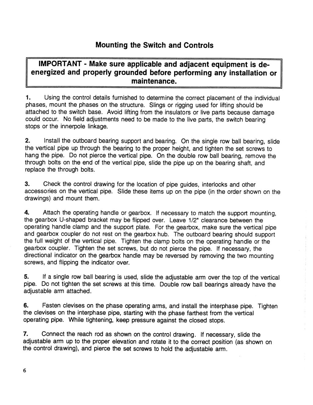
1 USCO Power Equipment Corporation Post Office Box 66 Leeds, Alabama Telephone (205) Facsimile (205) Installation, Operation and Maintenance Manual Type AGCH5V Group Operated, Outdoor, VEE Center Break Air Switch 15 kv through 230 kv 1200 to 4000 Amperes IMPORTANT - Make sure applicable and adjacent equipment is deenergized and properly grounded before performing any installation or maintenance.
2
3
4 If the insulators have been installed at the factory, skip to Page 6, Mounting the Switch and Controls Installation of Insulators 1. Uncrate the switch phases and cut the tie wires that hold the switch closed. Operate and inspect each phase for proper operation or any shipping damage. 2. With the phases closed, remove the live parts from the switch base. Mount the insulators on the switch bearings. Hand tighten the insulator bolts. 3. Place the live parts on top of the insulators again with the phase closed. Line up the painted match marks on the lower operating arms with the mark on the hinge blade supports to ensure proper alignment. Hand tighten the upper insulator bolts. 4. Make sure that the lower operating arm is against the closed stop, the blades are centered on the switch base and the contacts are firmly seated. Tighten all insulator bolts, starting with the lower bolts and working up. Check to make certain that the operating arm stays against the closed stop. Even 1/16 clearance may affect the timing of the switch and affect the position of the blade in the open position. 5. Operate the switch phase from the fully closed to the fully open position, then bring the blades back to the closed position to make sure the male contact is timed with the center of the jaw. If not, close the switch, loosen the insulator cap bolts on top, push the blades to the full closed position and tighten the cap bolts while holding the blades closed. Check the contact alignment as shown on page 8. If adjustment is needed up, down, in or out, close the switch, loosen the peg bolts on each side of the switch base and adjust the leveling studs as shown on page 10 to align the contacts. If leveling bolts are not furnished, use shims under the lower insulator cap to align the contacts. 6. No field adjustments need to be made to the live parts, the bearing stops or the innerpole linkage. All of these items have been adjusted at the factory. 7. Close all three phases and re-tie the operating arm against the closed stop. Ensure that the operating arm is firmly against the closed stop. 4
5
6
7 Operating Arm Pipe Clevis Reach Rod Adjustable Arm Outboard Bearing Main Switch Bearing Vertical Pipe Pipe Guide Clearance Position Indicators Swing Handle Control Swing Handle Control
8 Switch and Control Adjustment 1. The Adjustable arm normally will be set at a trial radius to travel 180 degrees and toggle in the open and closed positions. Check the arm trial radius given on the control drawing. 2. Operate the switch. If the adjustable arm does not travel 180 degrees, but the switch is fully open, the trial radius length is too long. If the adjustable arm travels 180 degrees, but the switch is not fully open, the trial radius is too short. Close the switch, loosen the four clamp bolts and adjust the length of the arm ¼ as needed. Reset and tighten the bolts. Check the operation a few tries are usually necessary to fine tune the switch. Arcing Horn Inspection and Adjustment Check the arcing horns, if furnished, ensuring that continuous contact occurs after breaking and before making the main contacts. If not, slightly bend the arcing horns to make contact. Jaw Contact Alignment The switch contact pressure is set at the factory. No adjustments are needed. The alignment should be as shown below (if adjustment is necessary use the leveling studs or shims): 8
9 Terminal Connections For non-plated terminal pads, clean the terminal pads with a stiff wire brush until there is a clean metallic surface. For plated surfaces, do not wire brush, but clean lightly with steel wool. Immediately coat the connection surfaces with a non-gritted corrosion inhibiting joint compound such as No. 2 EJC. Wire brush the pad surface again through the compound, attach the conductor terminals to the switch terminal pads and torque the connection bolts. Do not wipe off the excess compound that squeezes out. This will serve as a moisture seal for the connection. Minimum Recommended Torque Values for ½ Diameter Bolts Bolt Material Lubricated Threads Foot-Pounds Dry Threads Foot-Pounds Aluminum Steel, Galvanized or Stainless Final Checklist 1. As a final check, operate the switch, checking that (1) the blades line up in the open position, (2) when closing, the blades strike the arcing horn or enter the jaw contact at approximately the same time (3) when closed, the male contact is aligned in the female jaw contact and centered on the switch base and (4) male blade should always be mounted on the drive side of the bearing. 2. After all adjustments are completed, tighten all set screws to pierce the pipe. 3. Do not apply grease to the jaw contacts. The contacts have been lubricated at the factory with dry graphite. 9
10
11 Changing Switch Opening Direction *Please Refer to Factory
12 Installation Troubleshooting Problem: In the closed position the operating arms are against the closed stops, but in the open position, the switch phases are not fully open and the operating arms are not against the open stops. Solution: With the switch closed, loosen the clamp bolts on the adjustable arm and lengthen the adjustable arm by about ¼. Tighten the clamp bolts (for threaded clevises, reset the length of the turnbuckle and pin the clevis) and operate the switch. If the operating arms still do not hit the stops, lengthen the adjustable arm some more. If the operating arms hit the stops too hard, shorten the adjustable arm slightly. It may take a few tries to fine tune the switch operation. Problem: In the closed position, the operating arms are against the stops, but when opened the operating arms push the open stops hard and the adjustable arm will not toggle. Solution: With the switch closed, loosen the clamp bolts on the adjustable arm and shorten the adjustable arm by about ¼. Tighten the clamp bolts (for threaded clevises, reset the length of the turnbuckle and pin the clevis) and operate the switch. If the operating arms still hit the stops hard, shorten the adjustable arm some more. If the operating arms do not hit the open stops, lengthen the adjustable arm slightly. It may take a few tries to fine tune the switch operation. Problem: One or two of the phase operating arms are against the open or closed stops, but the other phase(s) are not. Solution: With the switch closed, loosen the clevises on the inter-phase pipe and push all operation arms against the closed stops. While keeping pressure against the stop, tighten the clevis. (For threaded clevises, release the locknut and turn the turnbuckle not to push the operating arm against the stop.) 12

13
14
15

16
17
18
19
20 1995 USCO Power Equipment Corporation USCO Power Equipment Corporation Post Office Box 66 Leeds, Alabama Telephone (205) Facsimile (205)
IB-FAS3 Mar Type FAS THRU 115Kv Amp 61 KA Momentary. Vertical-Break, Gang-Operated Outdoor Air Disconnect Switch.
 IB-FAS3 Mar. 2014 Type FAS3 7.5 THRU 115Kv 600 1200 Amp 61 KA Momentary Vertical-Break, Gang-Operated Outdoor Air Disconnect Switch Page 0 Contents Subject Page Receiving and Handling................................................
AVX. Operation and Maintenance Manual AVX 1200A A 15kV to 362kV. ALUMINIUM VERTICAL BREAK DISCONNECT SWITCH 15kV to 362kV 1200A A
 Operation and Maintenance Manual AVX AVX AVX-1200 2000-15 362KV-E R00 1 TABLE OF CONTENTS 1 General Description...4 1.1 General...4 1.2 Contacts...5 1.3 Switch Base...5 1.4 Insulator Stack Bearing Assemblies...5
TYPE CBL-T. Copper Center Break V Disconnect Switch kv, 1200A INSTALLATION & INSTRUCTION MANUAL
 TYPE CBL-T Copper Center Break V Disconnect Switch 15.5 72.5 kv, 1200A INSTALLATION & INSTRUCTION MANUAL The Quality Name in High Voltage Switching Page II The Quality Name in High Voltage Switching Safety
Instructions for Installation and Operation
 S&C Alduti-Rupter Switches Outdoor Distribution Three-Pole Vertical-Break Style Reciprocating Operating Mechanism 25/34.5 kv and 34.5 kv Instructions for Installation and Operation TABLE OF CONTENTS Section
Type EB, EBB, EBF and VEB DOUBLE SIDE BREAK SWITCHES 38 kv through 362 kv 600 to 3000 Ampere
 Type EB, EBB, EBF and VEB DOUBLE SIDE BREK SWITCHES 8 kv through 62 kv 600 to 000 mpere TYPE EB 1 Morpac Industries, Inc. 2725 East Ginter Road Tucson, rizona 85706 520-294-452 FX 520-294-2 Type EB, EBB
CLEAVELAND / PRICE INC. Type RL-C Side Break Switch kv A. Bulletin DB-104E12
 Bulletin DB-104E12 Type RL-C Side Break Switch 7.2-69 kv 600-2000 A. CLEAVELAND / PRICE INC. 14000 Rt. 993, Trafford, PA 15085 (724) 864-4177 FAX (724) 864-9040 Email: sales@cleavelandprice.com Type RL-C
Product Specifications for Aluminum Vertical Break Switches
 1. General a) This specification covers the design, manufacture, and shipment of aluminum vertical break switches, both air-break and load-break configurations, for substation and transmission switching
www. ElectricalPartManuals. com INSTRUCTIONS "INERTEEN AND OIL INSULATED FEEDER SWITCHES DESCRIPTION INSTALLATION MAINTENANCE
 r \ FIG. 1. Cutaway View of Typical Switch. I.L. 46-723-1 DESCRIPTION INSTALLATION MAINTENANCE INSTRUCTIONS THE INERTEEN AND OIL INSULATED FEEDER SWITCH provides complete switching facilities in a minimum
Operator s Manual Series ATB Automatic Transfer & Bypass Isolation Switches 150, 260, and 400 amp sizes A. Rating Label.
 Operator s Manual 7000 Series ATB Automatic Transfer & Bypass Isolation Switches 150, 260, and 400 amp sizes TABLE OF CONTENTS Note: Refer to the outline and wiring drawings provided with your 7000 Series
TYPE V CENTER BREAK SWITCH
 TYPE V CENTER BREAK SWITCH 3-PHASE, GROUP-OPERATED (SUBSTATION AND TRANSMISSION APPLICATIONS) *Available in Copper Horizontal upright, vertical or underhung mounting 15KV through 230KV 600A through 4000A
TYPE AST. Grounding Switch. ALL Ratings INSTALLATION & INSTRUCTION MANUAL
 TYPE AST Grounding Switch ALL Ratings INSTALLATION & INSTRUCTION MANUAL The Quality Name in High Voltage Switching Page I The Quality Name in High Voltage Switching Safety Information Page II The Quality
CENTER BREAK GROUP OPERATED AIR BREAK SWITCHES RATED 15.5kV THROUGH 170kV EFFECTIVE DATE: 10/25/16 REV B
 CENTER BREAK GROUP OPERATED AIR BREAK SWITCHES RATED 15.5kV THROUGH 170kV EFFECTIVE DATE: 10/25/16 REV B TCV2 Hubbell has a policy of continuous product improvement. Please visit hubbellpowersystems.com
Instructions for Installation and Operation
 S&C Alduti-Rupter Switches Three-Pole Side-Break Heavy-Duty Style Reciprocating Operating Mechanism 34.5 kv Instructions for Installation and Operation TABLE OF CONTENTS Section Page Section Page INTRODUCTION
Operators/Accessories. Type V2-CA Aluminum. Vertical Break Switch. Ordering Information Furnish: Available Accessories. Standard Operator Features
 Vertical Break Switch Operators/Accessories Ordering Information Furnish: Switch type Voltage Amperage Momentary rating BIL level Mounting position Operator type Accessories required Base mounting holes
TYPE EC-1V. Aluminum Center Break Vee Disconnect Switch. ALL Ratings INSTALLATION & INSTRUCTION MANUAL
 TYPE EC-1V Aluminum Center Break Vee Disconnect Switch ALL Ratings INSTALLATION & INSTRUCTION MANUAL The Quality Name in High Voltage Switching Page I The Quality Name in High Voltage Switching Page II
Calandra Racing Concepts
 Calandra Racing Concepts Carpet Knifeä Version 3 Assembly and Setup Manual Congratulations! You now own the best 1/12th scale car on the market today, the Carpet Knifeä Version 3. This completely new car
Aluminum Vertical Break Switch 345 kv, 1300 kv BIL 2000 A A.
 Bulletin DB-106AEH11 Type V2-CA Aluminum Vertical Break Switch 345 kv, 1300 kv BIL 2000 A.- 3000 A. Designed for Simplicity Testing of the 345 kv V2-CA to IEEE Standards. The Cleaveland/Price 345 kv V2-CA
INSTRUCTIONS Ç CAUTION. S&C Power Fuses Types SMD-1A, SMD-2B, SMD-2C, and SMD-3. For Field Assembly and Installation NOTE INSTRUCTION SHEET
 S&C Power Fuses Types SMD-1A, SMD-2B, SMD-2C, and SMD-3 Outdoor Transmission Mountings Rated 34.5, 46, and 69 kv INSTRUCTIONS For Field Assembly and Installation TABLE OF CONTENTS Section Page Number INTRODUCTION........................................1
TYPE EC-1. Aluminum Center Side Break Disconnect Switch. For kv Ratings INSTALLATION & INSTRUCTION MANUAL
 TYPE EC-1 Aluminum Center Side Break Disconnect Switch For 38 362 kv Ratings INSTALLATION & INSTRUCTION MANUAL The Quality Name in High Voltage Switching Page II The Quality Name in High Voltage Switching
Installation and Operation
 S&C Omni-Rupter Switches Outdoor Distribution 14.4 kv and 25 kv Three-Pole Side-Break Integer Style Hookstick-Operated Vertical and Tiered-Outboard Mounting Configurations Installation and Operation Table
Loose Components. VetPro 5000 Wall / Cabinet Mount Installation. Applies to Models:
 VetPro 5000 Wall / Cabinet Mount Installation warning Equipment not suitable for use in the presence of a flammable anesthetic mixture. Applies to Models: 8001-001 8001-002 8001-005 8001-006 Loose Components
Florham Park, NJ USA Call (ASCO) for sales or service
 for sales or service") Operator s Manual 4000 Series ATS Automatic Open-Transition Transfer Switches D design 30 230A, J design 260 600A, H-design 800 1200A, G-design 1600 4000A, F-design 4000A DANGER is used in this manual
Operator s Manual 4000 Series ATS Automatic Open-Transition Transfer Switches D design 30 230A, J design 260 600A, H-design 800 1200A, G-design 1600 4000A, F-design 4000A DANGER is used in this manual
Product Specifications for Phase Over Phase GOABS(r)
") 1. General a) This specification covers the design, manufacture, and shipment of phase-over-phase, 1-way, 2-way, 3-way, and 4-way, gang-operated disconnecting switches, both air-break and load-break, for
1. General a) This specification covers the design, manufacture, and shipment of phase-over-phase, 1-way, 2-way, 3-way, and 4-way, gang-operated disconnecting switches, both air-break and load-break, for
Installation. S&C Omni-Rupter Switches Outdoor Distribution 14.4 kv and 25 kv
 S&C Omni-Rupter Switches Outdoor Distribution 14.4 kv and 25 kv Three-Pole Side-Break Integer Style Hookstick-Operated Vertical and Tiered-Outboard Mounting Configurations Catalog Number Supplement R3
Aluminum Vertical Break Switch kv A.
 Bulletin DB-C106AA05 Type V2-CA Aluminum Vertical Break Switch 7.2-69 kv 600-2000 A. Designed for Simplicity V2-CA APPLICATION The Cleaveland/Price V2-CA is a three pole, group operated, aluminum vertical
Next, chase the threads in the lower A-arm mounts with the 5/8-18 tap and blowout any remaining particles.
 Next, chase the threads in the lower A-arm mounts with the 5/8-18 tap and blowout any remaining particles. Now, apply some anti-seize to the threads of the pivot stud. Also put anti-seize inside the bore
Installation, Operation, and Maintenance
 S&C Regulator Bypass Switches Outdoor Distribution (14.4 kv through 25 kv) Type XL (Sequenced) and Type NL (Non-sequenced) Installation, Operation, and Maintenance Table of Contents Section Page Section
3 Suspension System. Dodge Ram Dodge Ram Part#:
 Part#: 012311 3 Suspension System Dodge Ram 3500 2013 Dodge Ram 2500 2014 Rev. 041917 491 W. Garfield Ave., Coldwater, MI 49036. Phone: 517-279-2135 E-mail: tech-bds@sporttruckusainc.com Read And Understand
Copper Double Break Switch
 Bulletin DB-104DB09 Type DB-C Copper Double Break Switch 7.2 kv - 69 kv 600 A. - 2000 A. 14000 Rt. 993, Trafford, PA 15085 (724) 864-4177 FAX (724) 864-9040 E-mail: sales@cleavelandprice.com Type DB-C
TYPE EE and EEB CENTER- SIDE-BREAK SWITCH TYPE VEE and CBV CENTER BREAK V SWITCH 1200, 1600, 2000 & 3000 Amperes 7.
 YP and B CNR- SI-BRAK SWIC YP V and CBV CNR BRAK V SWIC 100, 1600, 000 & 3000 Amperes 7.5 through 36 kv YP YP CBV Morpac Industries, Inc. 75 ast Ginter Road ucson, Arizona 85706 50-94-345 FAX 50-94-333
Florham Park, NJ USA Call (ASCO) for sales or service
 for sales or service") Operator s Manual 7000 Series ATS Automatic Transfer Switches D design, 30 through 230 A DANGER is used in this manual to warn of a hazard situation which, if not avoided, will result in death or serious
Operator s Manual 7000 Series ATS Automatic Transfer Switches D design, 30 through 230 A DANGER is used in this manual to warn of a hazard situation which, if not avoided, will result in death or serious
Operator s Manual Series ADTS Automatic Delayed Transition Transfer Switches 150 through 4000 amp. Rating Label. Nameplate A
 Operator s Manual 7000 Series ADTS Automatic Delayed Transition Switches 150 through 4000 amp. Note: Refer to the outline and wiring drawings provided with your 7000 Series ADTS for all installation and
Operator s Manual Series ATS Automatic Transfer Switches 30 through 4000 amp. Rating Label. Nameplate C TABLE OF CONTENTS
 Operator s Manual 7000 Series ATS Automatic Switches 30 through 4000 amp. Note: Refer to the outline and wiring drawings provided with your 7000 Series ATS for all installation and connection details and
www. ElectricalPartManuals. com
 Instructions for Parcel-Line Type DH-P Circuit Breakers with Post Insulator Type Pole Units (Supplements I. B. 32-253-2) Westinghouse Electric Corporation Switchgear Division, East Pittsburgh, Pa. 15112
Copper Vertical Break Switch kv A.
 Bulletin DB-106C05 Type V2-C Copper Vertical Break Switch 7.2-69 kv 600-2000 A. Designed for Simplicity V2-C APPLICATION The Cleaveland/Price V2-C is a three pole, group operated, copper vertical break
CABLE CUTTER INSTRUCTION MANUAL
 INSTRUCTION MANUAL For additional copies at no charge order 999 6443.0 750 CABLE CUTTER Read and understand all of the instructions and safety information in this manual before operating or servicing this
Operator s Manual Series ACTS Automatic Closed Transition Transfer Switches 150 through 4000 amps A. Rating Label.
 Operator s Manual 7000 Series ACTS Automatic Closed Transition es 150 through 4000 amps TABLE OF CONTENTS section-page INSTALLATION... 1-1 Mounting and Line Connections... 1-1 Auxiliary Circuits and Harness...
Installation Instruction for Phase-Over-Phase GOABS(r)
") Thank you for purchasing a SEECO phase-over-phase GOABS switch. We are pleased to be able to provide this product to you and we believe that it will meet or exceed your performance expectations. SEECO
Thank you for purchasing a SEECO phase-over-phase GOABS switch. We are pleased to be able to provide this product to you and we believe that it will meet or exceed your performance expectations. SEECO
J & D Machine / Hyperdrive / MSA 3711 Moon Bend Rd. Chapel Hill, TN 37034
 J & D Machine / Hyperdrive / MSA 3711 Moon Bend Rd. Chapel Hill, TN 37034 www.hyperdriveracing.com 1 You now own a state of the art 1/10 scale oval race car. The Hyperdrive Assault has gone through months
50 Hanover Road, Florham Park, New Jersey USA For sales or service call (ASCO)
") Operator s Manual 7000 Series ATS Automatic Transfer Switches H design 600 through 1200 amps TABLE OF CONTENTS section-page INSTALLATION... 1-1 Mounting and Line Connections... 1-1 Auxiliary Circuits and
Operator s Manual 7000 Series ATS Automatic Transfer Switches H design 600 through 1200 amps TABLE OF CONTENTS section-page INSTALLATION... 1-1 Mounting and Line Connections... 1-1 Auxiliary Circuits and
section-page Table 1. Transfer switching device ratings. Conditional short circuit current
 Operator s Manual 7000 Series ATS Automatic Transfer Switching Equipment D design 30 through 200 amperes TABLE OF CONTENTS section-page INSTALLATION... 1-1 Enclosures and Mounting... 1-1 Power Connections...
Assembly Instructions. Before You Start. Assembly Instructions. 3-Point Bedded Irrigation. Used with: 3-Point Drills
 Great Plains Mfg., Inc. Assembly Instructions! 3-Point Bedded Irrigation Used with: 3-Point Drills When you see this symbol, the subsequent instructions and warnings are serious - follow without exception.
50 Hanover Road, Florham Park, New Jersey USA For sales or service call (ASCO)
") Operator s Manual 7000 Series ACTS Automatic Closed Transition Transfer Switches E design 150 400A, F design 600 800A, G design 1000 4000A, F design 3000 4000A, DANGER is used in this manual to warn of
Operator s Manual 7000 Series ACTS Automatic Closed Transition Transfer Switches E design 150 400A, F design 600 800A, G design 1000 4000A, F design 3000 4000A, DANGER is used in this manual to warn of
www. ElectricalPartManuals. com (!B) I 1-T-E IMPERIAL CORPORATION -- INSTRUCTIONS THRU 4000 AMPERES OUTDOOR AIR SWITCHES
 I 1-T-E IMPERIAL CORPORATION -- INSTRUCTIONS THRU 4000 AMPERES OUTDOOR AIR SWITCHES") OUTDOOR AIR SWITCHES IB-1342A -- INSTRUCTIONS - TYPES TTR49 AND TTL49 GROUP OPERATED, VERTICAL BREAK SWITCHES 7.2 THRU 230 KV 400 THRU 4000 AMPERES (!B) I 1-T-E IMPERIAL CORPORATION 2 9 \ TTR49 TTL49 HIGH
OUTDOOR AIR SWITCHES IB-1342A -- INSTRUCTIONS - TYPES TTR49 AND TTL49 GROUP OPERATED, VERTICAL BREAK SWITCHES 7.2 THRU 230 KV 400 THRU 4000 AMPERES (!B) I 1-T-E IMPERIAL CORPORATION 2 9 \ TTR49 TTL49 HIGH
TYPE EV-1 SCE EDITION
 TYPE EV-1 SCE EDITION Aluminum Vertical Break Disconnect Switch 550kV Single Pole (Only) INSTALLATION & INSTRUCTION MANUAL The Quality Name in High Voltage Switching Page II The Quality Name in High Voltage
CENTERLINE 2100 Motor Control Centers 600A, 800A, and 1200A Bolted Pressure Contact Switch
 Instructions CENTERLINE 2100 Motor Control Centers 600A, 800A, and 1200A Bolted Pressure Contact Switch CENTERLINE 2100 Motor Control Centers Introduction The intent of this publication is to provide field
Shown with optional GFR-1017R Body Posts. J & D Machine / Hyperdrive / MSA 3711 Moon Bend Rd. Chapel Hill, TN
 Shown with optional GFR-1017R Body Posts J & D Machine / Hyperdrive / MSA 3711 Moon Bend Rd. Chapel Hill, TN 37034 www.hyperdriveracing.com 1 You now own a state of the art 1/10 scale oval race car. The
FR01A Fender, Bolted-On
 Uniform Procedures For Collision Repair UPCR FR01A Fender, Bolted-On 1. Description This procedure describes the repair and complete replacement of a bolted-on aluminum fender. Inspection and evaluation
Operator s Manual Series ATS Automatic Transfer Switches 600 through 1200 amps
 Operator s Manual 7000 Series ATS Automatic Switches 600 through 1200 amps 600---1000 amp. size An experienced licensed electrician must install the ATS. DANGER is used in this manual to warn of high voltages
and Original Series Pickup Lift Mounting Instructions Fleetside Chevy & GMC Trucks Fleetside 4-door Chevy & GMC Trucks T-100
 r ve and Original Series Pickup Lift Mounting Instructions Fleetside Chevy & GMC Trucks - 1960-1987 Fleetside 4-door Chevy & GMC Trucks - 1988-1991 Preparing the Gate 1. Remove the mounting hardware which
Chevy Nova Pro-Touring Front Suspension Installation Instructions
 1962-1967 Chevy Nova Pro-Touring Front Suspension Installation Instructions 1-800-984-6259 www.totalcostinvolved.com 1 Pro-Touring Clip A-Arm Assembly Sway Bar Assembly Fender Panel Kit 8 7/16-20 * 1 ¼
* Caution : Brushes are brittle. Do not brake them. 3UE
 The IVOPROP operates on a COMPLETELY UNIQUE adjustable pitch system that allows for substantially less hardware and rotating mass than any other ground pitch adjustable prop. The unique pitch adjustment
Mirrored from:
 Mirrored from: http://www.wranglerforum.com/f274/install-synergy-suspension-ball-joints-write-up-147062.html 03-18-2012, 02:43 AM #1 SilverSport Supporting Member WF Supporting Member Install Synergy Suspension
S&C Circuit-Switchers Mark VI Installed on S&C Mounting Pedestals 84- through 102-inch Phase Spacing Outdoor Transmission (69 kv through 138 kv)
") S&C Circuit-Switchers Mark VI Installed on S&C Mounting Pedestals 84- through 102-inch Phase Spacing Outdoor Transmission (69 kv through 138 kv) Installation Table of Contents Section Page Section Page
S&C Circuit-Switchers Mark VI Installed on S&C Mounting Pedestals 84- through 102-inch Phase Spacing Outdoor Transmission (69 kv through 138 kv) Installation Table of Contents Section Page Section Page
3IN1 SELF-CLOSING HINGE USER GUIDE
 3IN1 SELF-CLOSING HINGE USER GUIDE (TOP, MIDDLE, BOTTOM) = (SS, HA, SA) For door < 260 pounds (120 kg) Before Hinge Adjustment The quality of door installation is super important and could affect the self-closing
Installation Instructions
 Preparing your vehicle to install your brake system upgrade 1. Rack the vehicle. 2. If you don t have a rack, then you must take extra safety precautions. 3. Choose a firmly packed and level ground to
Cantilever Series Mounting Instructions Fullsize Sprinter Van (US) All except WB (AA) present
 All except WB (AA) present") Fullsize Sprinter Van (US) All except 3500 144 WB (AA)- 2007-present Preparing the Gate 1. Remove the platform, mounting kit, license plate assembly, and bridge assemblies, which are banded to the main
Fullsize Sprinter Van (US) All except 3500 144 WB (AA)- 2007-present Preparing the Gate 1. Remove the platform, mounting kit, license plate assembly, and bridge assemblies, which are banded to the main
INSTRUCTIONS For Field Assembly, Installation, and Maintenance
 INSTRUCTIONS For Field Assembly, Installation, and Maintenance TABLE OF CONTENTS Section Page Number INTRODUCTION........................................1 ASSEMBLING AND INSTALLING MOUNTINGS............2
Operator s Manual Series ADTS Automatic Delayed Transition Transfer Switches, amps
 Operator s Manual 7000 Series ADTS Automatic Delayed Transition Switches, 600 1200 amps 600---1000 amp. sizes An experienced licensed electrician must install the ADTS. DANGER is used in this manual to
Transmission Switching
 CATALOG BULLETIN GENERAL APPLICATION Southern States supplies a wide offering of Transmission Switching solutions in response to an increasing need for improved system reliability and reduced installation
Detroit Speed, Inc. Selecta-Speed Wiper Kit Corvette P/N:
 Detroit Speed, Inc. Selecta-Speed Wiper Kit 1968-72 Corvette P/N: 121621 A downpour of rain will no longer hinder your ability to clearly see the road. The Detroit Speed Selecta-Speed Wiper Kit provides
Catalog Number Identification with Elements Explained
 Installation Manual 920 Remote Control Switches 30 through 225 ampere sizes This Installation! Manual is for green nameplate ASCO 920s only. For black nameplate ASCO 920s refer to Owners Manual 2D4920
Installation and Operation
 S&C Alduti-Rupter Switches Outdoor Distribution (46 kv) Three-Pole Double-Break Integer Style Reciprocating Operating Mechanism No Catalog Number Supplement and Operation Table of Contents Section Page
VBM Fault Interrupter Instructions
 VBM Fault Interrupter Instructions Revision: July 2007 Supersedes: June 2007 THREE PHASE THREE PHASE THREE PHASE 15kV/25kV Grounded 400A 25kV 200A 38kV 300A 15kV/25kV Grounded 600A 25kV 300A 25kV 400A
Type EV-2. Aluminum Vertical Break Disconnect Switch. All Ratings INSTALLATION & INSTRUCTION MANUAL
 Type EV-2 Aluminum Vertical Break Disconnect Switch All Ratings INSTALLATION & INSTRUCTION MANUAL The Quality Name in High Voltage Switching Page II Page III The Quality Name in High Voltage Switching
lu. ücr ii- w - ~ ~. It It ~ o B Belt Drive Hydraulics FORD ~ èf ~ o (/ (/ ~ -c w $: $: cr oi- -czcr ~ g ~ cr
 lu. SYSTEM FORD va 7.3L Diesel 1994 1/2-97 Direct Injection w-w/o AC 7542B Belt Drive Hydraulics l- ~ èf ~ ~ o 0 ~ ~. o Q.'( l. ~d It It ~ s: cr oi- -czcr w ~. -c.. (/ o -c w cr ii-!j ücr "- cr ~ o cr
Power & High Voltage Joslyn Hi-Voltage Overhead Reclosers & Switches H-220. Series HVI Hi-Velocity Interrupter Attachment
 Use load interrupter attachments to enable loop sectionalizing, line dropping, load breaking and transformer-magnetizing current interruption. Increase the capability of your disconnect switches by adding
Unitized Quick Install Switches for Transmission Applications
 Bulletin DB-600A12 Unitized Quick Install Switches for Transmission Applications Vertical Break Switches Center Break V Switches CLEAVELAND / PRICE INC. 14000 Rt. 993, Trafford, PA 15085 (724) 864-4177
Hydraulic Chute USAGE INSTRUCTIONS
 1. Before Using hute Place attlemaster hydraulic chute on level area. Grease all zerk fittings on chute. Spray aerosol oil on all latches, hinges and linkages. Unscrew and remove plastic shipping plug
First, check and record the camber and caster readings, they will be adjusted later.
 First, check and record the camber and caster readings, they will be adjusted later. The caliper-mounting bosses are machined perpendicular to the spindle so they are an excellent place for the level.
STRESS-TEK, INC S. 194 th Street Kent, WA June 2011 Stress-Tek, Inc. Doc Rev A
 Installation, Setup and Calibration of Vulcan Deflection Sensors on Hendrickson 462/463 and Haulmaxx Equalizing Suspension Beams (Includes Models HN 402, HN 462, HN FR, RT 463, RTE 463, HMX and HMX 400.)
FR11A Fender, Welded-On
 Uniform Procedures For Collision Repair FR11A Fender, Welded-On 1. Description This procedure describes the repair and complete replacement of a welded-on aluminum fender. Inspection and evaluation requirements
N. 15th Street, Middlesboro, KY TARP-N-GO SYSTEMS INSTALLATION INSTRUCTIONS
 1-800-248-7717 1002 N. 15th Street, Middlesboro, KY 40965 TARP-N-GO SYSTEMS INSTALLATION INSTRUCTIONS Congratulations on your purchase of a Mountain Tarp Tarp-N-Go tarping system. With tarping systems
Cantilever Series Mounting Instructions Chevy Express (AD) present
 present") Chevy Express (AD)- 2003-present Preparing the Gate 1. Remove the platform, mounting kit, and bridge assemblies, which are banded to the main assembly. Leave the banding that holds the folding cylinder
Chevy Express (AD)- 2003-present Preparing the Gate 1. Remove the platform, mounting kit, and bridge assemblies, which are banded to the main assembly. Leave the banding that holds the folding cylinder
Tooling Assistance Center
 Safeguards are designed into this application equipment to protect operators and maintenance personnel from most hazards during equipment operation. However, certain safety precautions must be taken by
Snowplow Installation Instructions 8-1/2' and 9-1/2' MVP Multiposition V Plow
 WESTERN PRODUCTS, P.O. BOX 245038, MILWAUKEE, WI 53224-9538 Lit. No. 63886 August 31, 2004 Snowplow Installation Instructions 8-1/2' and 9-1/2' MVP Multiposition V Plow CAUTION Read this document before
Installation And Operation
 S&C Series 2000 Circuit-Switchers Outdoor Transmission Model 2020 With Vertical Interrupters and Side-Break Power-Operated Disconnect 69 kv through 138 kv Installation And Operation Table of Contents Section
650 Series Cargo Van Lift Mounting Instructions Fullsize Ford 1992-Present
 TOMMY GATE OWNER'S / OPERATOR'S MANUAL 650 Series 650 LB Capacity 650 Series Cargo Van Lift Mounting Instructions Fullsize Ford 1992-Present Installing the Base Plate 1. Examine the interior and exterior
ATLAS TRANSFER CASES CABLE SHIFTER units built before 4/30/12
 Paso Robles, CA 93447 PAGE 1 OF 5 Telephone: (800) 350-2223 Fax: (805) 238-4201 Page Rev. Date: 05-12-15 KIT CONSISTS OF: No. Qty Part No. Description 1. 1 302051 TWIN STICK BASE MOUNT 2. 1 302060 TWIN
ADJUSTING THE GANG ANGLE
 ADJUSTING THE GANG ANGLE 1. Raise the machine until the discs are clear of the ground. 2. Set the diverter valve ( Fig. 1) to the angle position 3. Remove the appropriate angling pin (Fig 2 ) and replace
Cantilever Series Mounting Instructions Ram Promaster Extended Body (AH) Present
 Present") Ram Promaster Extended Body (AH)- 2014-Present Preparing the Gate 1. Remove the platform, mounting kit, and bridge assemblies, which are banded to the main assembly. Leave the banding that holds the folding
Ram Promaster Extended Body (AH)- 2014-Present Preparing the Gate 1. Remove the platform, mounting kit, and bridge assemblies, which are banded to the main assembly. Leave the banding that holds the folding
SELF DRILL SCREWS FILLER STRIP
 r ve Pickup Lift Mounting Instructions Fullsize Ford Trucks- F-150 2015-present Preparing the Gate 1. Remove the mounting hardware which is banded to the liftgate. 2. Verify mounting bracket kit (Figure
Cantilever Series Mounting Instructions Fullsize Sprinter Van (US) WB (AB) present
 WB (AB) present") Fullsize Sprinter Van (US) 3500 144 WB (AB)- 2007-present Preparing the Gate 1. Remove the platform, mounting kit, license plate assembly, and bridge assemblies, which are banded to the main assembly.
Fullsize Sprinter Van (US) 3500 144 WB (AB)- 2007-present Preparing the Gate 1. Remove the platform, mounting kit, license plate assembly, and bridge assemblies, which are banded to the main assembly.
CorkSport ort Mazda 3 Adjustable Shifter Mazdaspeed 3, Mazda 3 6-speed and Mazda3 SkyActiv 6-speed
 Part # Axl-6-963 CorkSport ort Mazda 3 Adjustable Shifter 2010-2013 Mazdaspeed 3, 2010-2013 Mazda 3 6-speed and 2012-2013 Mazda3 SkyActiv 6-speed Pre-Installation Notes: The CorkSport Adjustable Short
Chapter 52 DOORS -Title
 Chapter 52 DOORS 52-Title Page 1 January 23, 2012 INTENTIONALLY LEFT BLANK 52-Title Page 2 January 23, 2012 LIST OF EFFECTIVE PAGES Chapter Section Page No. Date 52 52-Title 1 January 23, 2012 2 January
Ford Super Duty 2-1/2 Radius Arm Kit. Ford F-250, F Part#:
 Part#: 013261-013262 Ford Super Duty 2-1/2 Radius Arm Kit Ford F-250, F350 2017-2019 Rev.101218 491 W. Garfield Ave., Coldwater, MI 49036. Phone: 517-279-2135 Web: www.bds-suspension.com E-mail: tech-bds@ridefox.com
25-kV Apparatus Bushings A Series (clamp-in) for Elbow to Air-Insulated Service 200 Amp and 600 Amp
 for Elbow to Air-Insulated Service 200 Amp and 600 Amp") Page 1 2018 Grounded Metal Equipment Plate Equipment Connection 15 kv or 25 kv Separable Insulated Connector (elbow) Grounded Metal Equipment Plate Equipment Connection Power Cable Power Cable ELRIM Cycloaliphatic
Page 1 2018 Grounded Metal Equipment Plate Equipment Connection 15 kv or 25 kv Separable Insulated Connector (elbow) Grounded Metal Equipment Plate Equipment Connection Power Cable Power Cable ELRIM Cycloaliphatic
Instructions for Installation
 S&C Circuit-Switchers Mark VI Outdoor Transmission 69 kv through 138 kv Option U, User-Furnished Mounting Structure Instructions for Installation TABLE OF CONTENTS Section Page Section Page INTRODUCTION
Installation Manual. E-design A Transfer Switches A
 ASCO 3ATS & 3NTS 3ATS & 3NTS E-design 260-400 A Transfer Switches DANGER is used in this manual to warn of a hazard situation which, if not avoided, will result in death or serious injury. is used in this
15-kV Wall-Mount Switchgear Three-Phase Indoor/Outdoor 600 Amp S&C Mini-Rupter Switch
 Page 1 2015 Kinked roof prevents standing moisture Glass reinforced barriers meet NEMA GPO-3 Standards 0.625" diameter copper ground bar Elliott air-insulated bushings accept IEEE Standard inserts and
Installation and Operation
 S&C Three-Shot Type XS Fuse Cutout Outdoor Distribution (4.16 kv through 15 kv) Installation and Operation Table of Contents Section Page Section Page Introduction Qualified Persons... 2 Read this Instruction
3ATS & 3NTS J-design 600 A 3ADTS & 3NDTS A Transfer Switches. Installation Manual. Installation A DANGER. Table of Contents WARNING
 ASCO 3ATS, 3ADTS, 3NTS, 3NDTS 3ATS & 3NTS J-design 600 A 3ADTS & 3NDTS 150-600 A Transfer Switches DANGER is used in this manual to warn of a hazard situation which, if not avoided, will result in death
Tourmaster Side Rails
 Assembly Instructions Tourmaster Side Rails 3-Step Model shown with optional Side and Back Rails CONTENTS Visit the Tourmaster Choral Risers web page at www.wengercorp.com for detailed instructions and
Catalog 14A January 2013
 Catalog 14A January 2013 Page 1 January 2013 Type AR (Automation-Ready) Switch 14.4kV, 25kV or 34.5kV 900 Amperes Continuous/Interrupt Description The Hubbell unitized Type AR switch is a distribution-level,
WAKEFIELD THERMAL SOLUTIONS ASSEMBLY PROCEDURE FOR PRECISION COMPRESSION MOUNTING CLAMP SYSTEMS
 WAKEFIELD THERMAL SOLUTIONS ASSEMBLY PROCEDURE FOR PRECISION COMPRESSION MOUNTING CLAMP SYSTEMS Clamp Assembly Application Procedure All illustrations assume the following parts: 143 series crossbar, 143-2
Tool-less Hinged Closure Installation, Operation, & Maintenance
 2612 Howard Street Louisville, KY 40211 USA Phone 502-774-6011 Fax 502-774-6300 Website: www.tubeturns.com For genuine Tube Turns Closure parts please contact factory: ttaftermarket@sypris.com Bulletin
USE THE PARTS LIST BELOW TO MAKE SURE YOUR KIT IS COMPLETE BEFORE INSTALLATION. IF ANY PIECES ARE MISSING, PLEASE CONTACT:
 1962-1967 Chevy Nova Pro-Touring Front Suspension Installation Instructions Tech line: 1-855-693-1259 www.totalcostinvolved.com Read and understand these instructions before starting any work! USE THE
CAT pin grabber quick change modifications.
 1 CAT pin grabber quick change modifications. Remove bucket from quick-change coupler Remove quick-change coupler and grind area shown here. Use gray plastic gage furnished with QC thumbs to determine
Rocky Mountain Brakes
 Rocky Mountain Brakes 1926-1927 INSTALLATION ALSO T TRUCKS CORRECT REAR AXLE FOR THE ABOVE YEARS HAS AN 11 BRAKE DRUM AND HOUSING (EX- CEPTION BEING T T TRUCK WORM DRIVE) AND DO NOT INTERCHANGE WITH THE
600 D 220 E 230 J Hanover Road, Florham Park, New Jersey USA For sales or service call (ASCO)
") Operator s Manual Series 386 Electrically Operated Non Automatic Switches J design 600 amps DANGER is used in this manual to warn of high voltages capable of causing shock, burns, or death. WARNINGisusedinthismanualtowarn
Operator s Manual Series 386 Electrically Operated Non Automatic Switches J design 600 amps DANGER is used in this manual to warn of high voltages capable of causing shock, burns, or death. WARNINGisusedinthismanualtowarn