INSTALLATION/SERVICE MANUAL. Intelligent Trailer Control Module (L31286)
|
|
|
- Nathaniel Bradley
- 5 years ago
- Views:
Transcription


1 MANUAL TM Intelligent Trailer Control Module (L31286)
2 Important Notice The products described within this literature, including without limitation, product features, specifications, designs, availability and pricing are subject to change by Haldex and its subsidiaries at any time without notice. This document and other information from Haldex, its subsidiaries and authorized distributors provide product and/or system options for further investigation by users having technical expertise. It is important that you analyze all aspects of your application and review the information concerning the product or system, in the current literature or catalog. Due to the variety of operating conditions and applications for these products or systems, the user, through their own analysis and testing, is solely responsible for making the final selection of the products and systems and assuring that all performance, safety and warning requirements are met.
3 Table of Contents Section Important Notices...1 Wheel End Speed Sensor Installation...2 ITCM ECU Power, 2M/3M Valve and Wheel End Speed Sensor Connections S/1M Configuration - Single or Multi-Axle Trailers...5 2S/2M Side-By-Side Configuration - Multi-Axle Trailers...6 4S/2M Side-By-Side Configuration - Multi-Axle Trailers...7 4S/2M Side-By-Side Configuration - Multi-Axle Trailers with Lift Axle(s)...8 4S/2M Axle-By-Axle Configuration - Multi-Axle Trailers...9 4S/2M Axle-By-Axle Configuration - Multi-Axle Trailers with Lift Axle(s) S/3M Configuration - Full and Semi-Trailers...11 ITCM 1M System Components...12 ITCM 2M System Components...13 ITCM FFABS Valve Overview...14 ITCM FFABS Valve Typical Tank Mounting Overview...15 Trailer Brake Control Valve (TBCV) Overview...16 ABS Power Drop Pin Out...17 Wheel End Speed Sensor Cable Routing...18 ITCM Testing Procedure...19 ITCM Diagnostic Tools ITCM Blink Code Diagnostics Tire Scale Factor Chart...28 ABS Warning Light Troubleshooting...29 ITCM PLC Diagnostic Codes/Troubleshooting SAE J1587/J1708 Fault Codes Related Parts...40 Solenoid Connections...41 Available for Download at haldex.com L ABS Service Components Catalog L31154W - PC Diagnostic Instruction Manual (web only) L31158W - PLC Info Center Instruction Manual (web only) L31287W - DIAG+ PC Diagnostic Instruction Manual (web only) L31292W - Info Center 2 Instruction Manual (web only) 2017 All Rights Reserved Material may only be reproduced with the written permission of Haldex. Page TOC
4 Important Notices Safety First This manual describes the correct installation process for the Haldex ITCM ABS 1M, 2M and 3M for trailers/dollies. The ITCM ABS may be used with either drum or disc brakes. Care must be taken during each phase of the installation in order to ensure the system is installed and working properly. Please follow your company s safety procedures at all times when installing this equipment. Be sure that you understand all instructions before you begin. Remove all air pressure and electrical power from the brake system before beginning work. The products described within this literature, including without limitation, product features, specifications, design, availability and pricing are subject to change by Haldex and its subsidiaries at any time without notice. This document and other information from Haldex, its subsidiaries and authorized distributors provide product and/or system options for further investigation by users having technical expertise. It is important that you analyze all aspects of your application and review the information concerning the product or system, in the current literature or catalog. Due to the variety of operating conditions and applications for these products or systems, the user, through their own analysis and testing, is solely responsible for making the final selection of the products and system and assuring that all performance, safety and warning requirements are met. Questions? If you have any questions on this product or any of the innovative products offered by Haldex, contact your local distributor for complete details. Technical Service or Troubleshooting help can be obtained by calling Haldex Technical Services Department at , Press 2. PAGE 1


5 Wheel End Speed Sensor Installation Sensor Block Allowable Placement The radial clocking position should be between 9 and 3 o clock. While the ABS performance is not affected with sensor location in the lower half of the axle, the structural integrity of the axle could be compromised. The sensor block placement should not interfere with any wheel end hardware. Speed Sensor Allowable Clearance The clearance between the speed sensor and the exciter ring should be ±.031. Any deviation will result in a reduction of the wheel speed sensor signal output. Check retention of the sensor within the sensor block - make sure the fit is tight. Note: Sensor block type and exciter ring depth may vary between manufacturers. General Positioning The position of the wheel speed sensor center axis to the exciter ring surface should be a close as possible to a 90 angle in both directions. Any deviation will result in a reduction of the wheel speed sensor signal output. The sensor block is generally welded to the axle. Refer to axle manufacturer s manual to ensure that welding won t affect structural integrity of the axle. PAGE 2
 CAN Network Cable ABS Power Cable Modulator Valve Solenoid Cable (23 Channel, 3M) Modulator Valve Solenoid Cable (22")

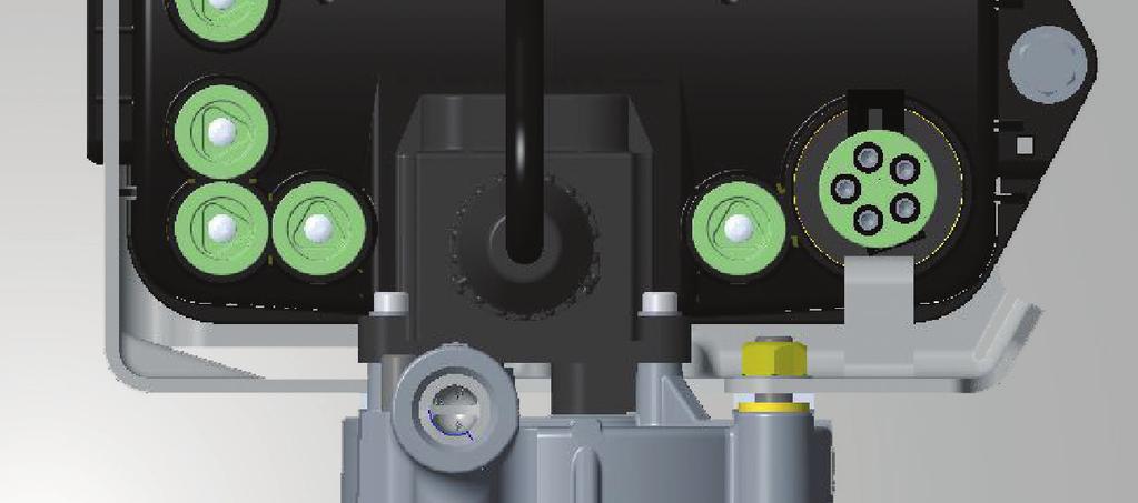
6 ITCM ECU Power, 2M/3M Valve and Wheel End Speed Sensor Connections S2B S1B S1A S2A ITCM ECU (Electronic Control Unit) Modulator Valve Solenoid Cable (21 Channel, 1M/2M/3M) CAN Network Cable ABS Power Cable Modulator Valve Solenoid Cable (23 Channel, 3M) Modulator Valve Solenoid Cable (22 Channel, 2M/3M) Note: If 2S/1M is desired, use Sensors (S1A and S1B). Use blanking plugs in un-used Sensor Connections. Note: When installing and servicing always apply small amount of dielectric grease to all electrical connections. Always ensure that ABS power cord is locked into place. PAGE 3


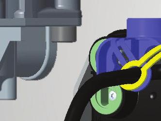
7 ITCM ECU Power, 2M/3M Valve and Wheel End Speed Sensor Connections (Cont d) Locking Tab Note: When installing and servicing always apply small amount of dielectric grease to all electrical connections. Modulator Valve Solenoid Cut-Away Section Showing Tab In Locked Position Tab In Locked Position Verify connection Locking Tab (shown above) is facing downward and secure. If the Modulator Valve Solenoid Cable can be removed without releasing the Locking Tab, verify connection orientation. Correct location of the wheel speed sensors at wheel ends is critical for proper ABS operation and troubleshooting. The ITCM will adjust the brake pressure in response to the input from the speed sensors. Incorrect installation or location of speed sensors, sensor block clips and exciter ring will result in poor ABS performance or sensors crossed leading to incorrect diagnostic troubleshooting. See Page 3 for the correct power and speed sensor connections on the ITCM ECU. See Haldex Trailer ABS Service Components Catalog L20243 for sensor extensions, if needed. PAGE 4
 should be installed on Side. S1B S1A 21 Make sure sensors are pushed firmly against the exciter ring. Note: For dollies and single axle trailers, Haldex recommends A8 ECU Configuration.")
8 2S/1M Configuration Single or Multi-Axle Trailers Recommended speed sensor wheel locations are shown in the figures below. Sensor (S1A) should be installed on Side. Sensor (S1B) should be installed on Side. S1B S1A 21 Make sure sensors are pushed firmly against the exciter ring. Note: For dollies and single axle trailers, Haldex recommends A8 ECU Configuration. Note: Any non-sensed axle can be utilized as a lift axle. Legend ITCM Air Hose Line: Modulator Valve: 21 Speed Sensors: S1A, S1B Single Axle (Air or Spring Suspension) S/1M Tandem Axle (Air Suspension) S/1M Tandem Axle (Spring Suspension) S/1M Tri-Axle (Air or Spring Suspension) S/1M Single Axle (Dolly) S/1M S1A S1B S1A 21 S1B S1A 21 S1B S1A 21 S1B S1A S1B PAGE 5
9 2S/2M Side-By-Side Configuration Multi-Axle Trailers Recommended speed sensor wheel locations are shown in the figures below. Sensor (S2A) should be installed on Side. Sensor (S2B) should be installed on Side. Modulator Valve 21 is plumbed to Side. Modulator Valve 22 is plumbed to Side. S2B S2A 21 Make sure sensors are pushed firmly against the exciter ring. Note: Any non-sensed axle can be utilized as a lift axle. Legend Air Hose Line: Modulator Valves:, Speed Sensors: S2A, S2B ITCM 22 Single Axle (Air or Spring Suspension) S/1M Tandem Axle (Spring Suspension) S/2M Tandem Axle (Air Suspension) S/2M Tri-Axle (Air or Spring Suspension) S/2M S2A S2B S2A S2B S2A S2B S2A S2B PAGE 6
10 4S/2M Side-By-Side Configuration Multi-Axle Trailers Recommended speed sensor wheel locations are shown in the figures below. Sensor (S1A, S2A) should be installed on Side. Sensor (S1B, S2B) should be installed on Side. Modulator Valve 21 is plumbed to Side. Modulator Valve 22 is plumbed to Side. S1B S2A S2B S1A 21 Make sure sensors are pushed firmly against the exciter ring. Note: Without lift axles. Legend Air Hose Line: Modulator Valves:, Speed Sensors: S1A, S2A, S1B, S2B ITCM 22 Tandem Axle (Air or Spring Suspension) Roaḏ S/2M Tri-Axle (Air or Spring Suspension) S/2M Quad-Axle (Air Suspension) S/2M Quad-Axle (Spring Suspension) S/2M S1A S1B S1A S1B S1A S1B S1A S1B S2A S2B S2A S2B S2A S2B S2A S2B PAGE 7
11 4S/2M Side-By-Side Configuration Multi-Axle Trailers with Lift Axle(s) Recommended speed sensor wheel locations are shown in the figures below. Sensor (S1A, S2A) should be installed on Side. Sensor (S1B, S2B) should be installed on Side. Modulator Valve 21 is plumbed to Side. Modulator Valve 22 is plumbed to Side. Make sure sensors are pushed firmly against the exciter ring. Any non-sensed axle can be lifted. One sensed axle can be used as a lift axle, but not both. Note: At least one axle with speed sensors has to be a non-lifting axle. Legend Air Hose Line: Modulator Valves:, S1B S2A S2B S1A 21 ITCM 22 Speed Sensors: S1A, S2A, S1B, S2B Tandem Axle S/2M Tri-Axle S/2M Quad-Axle S/2M Lift Axle Lift Axle Lift Axle S1A S1B Lift Axle Lift Axle S1A S1B S1A S1B S2A S2B Lift Axle S2A S2B S2A S2B PAGE 8
12 4S/2M Axle-By-Axle Configuration Multi-Axle Trailers This is a recommended configuration for spread axle applications. Recommended speed sensor wheel locations are shown in the figures below. Sensor (S1A, S1B) should be installed on Side. Sensor (S2A, S2B) should be installed on Side. Modulator Valve 21 is plumbed to the trailing axle(s). Modulator Valve 22 is plumbed closest to the King Pin. Make sure sensors are pushed firmly against the exciter ring. Note: The A Sensors must go with the 21 Modulator Valve and the B Sensors must go with the 22 Modulator Valve. Legend Air Hose Line: Modulator Valves:, S1B S2A S2B S1A 21 ITCM 22 Speed Sensors: S1A, S2A, S1B, S2B Tandem Axle (Air or Spring Suspension) S/2M Tri-Axle (Air or Spring Suspension) S/2M Quad-Axle (Air Suspension) S/2M Quad-Axle (Spring Suspension) S/2M Full Trailer (Air or Spring Suspension) S/2M S1B S2B S1B 22 S2B S1B 22 S2B S1B S2B S1B 22 S2B S1A S2A S1A 21 S2A S1A S2A S1A S2A S1A 21 S2A PAGE 9
13 4S/2M Axle-By-Axle Configuration Multi-Axle Trailers with Lift Axle(s) This is a recommended configuration for spread axle applications. Recommended speed sensor wheel locations are shown in the figures below. Sensor (S1A, S1B) should be installed on Side. Sensor (S2A, S2B) should be installed on Side. Modulator Valve 21 is plumbed to the trailing axle(s). Modulator Valve 22 is plumbed on axles closest to the King Pin. Make sure sensors are pushed firmly against the exciter ring. Any non-sensed axle can be lifted. For a sensed axle lift S1B and S2B must be used. S1B S2A S2B S1A 21 Note: The A Sensors must go with the Modulator Valve and the B Sensors must go with the 22 Modulator Valve. Lift Axle Control - Axle-By-Axle Configuration Note: At least one axle with speed sensors has to be on a non-lift axle. Legend ITCM Air Hose Line: Tandem Axle Tri-Axle Quad-Axle Modulator Valves:, S/2M S/2M S/2M Speed Sensors: S1A, S2A, S1B, S2B Lift Axle Lift Axle Lift Axle S1B 22 S2B Lift Axle Lift Axle S1B 22 S2B S1A S1B 22 S1B S2B S1A 21 S2A S1A 21 S2A S1A 21 S2A Lift Axle PAGE 10
14 4S/3M Configuration Full and Semi-Trailers Recommended speed sensor wheel locations are shown in the figures below. Sensor (S1A, S2A) should be installed on Side. Sensor (S1B, S2B) should be installed on Side. S1B S2A S2B S1A 21 Make sure sensors are pushed firmly against the exciter ring. Legend Air Hose Line: Modulator Valves:,, Speed Sensors: S1A, S2A, S1B, S2B 23 ITCM 22 Full Trailer (Air Suspension) Full Trailer (Air or Spring Suspension) Semi-Trailer Tandem Axle (Air or Spring Suspension) Semi-Trailer Tri-Axle (Air Suspension) 2S/1M 2S/1M S1A 23 S1B S1A 23 S1B 2S/1M S1A 23 S1B 2S/2M 2S/1M 2S/2M S1A 23 S1B S/2M 2S/2M S2A S2B S2A S2B S2A S2B S2A S2B PAGE 11
 ABS Relay Valve (6-port) ITCM 1M Valves Haldex PLC Diagnostic Tools PLC PC Diagnostics Kit ABS Relay Valve (2-port) 90 Sensor Cable Trailer Brake Control Valve (TBCV)")

15 ITCM 1M System Components See Haldex Trailer ABS Service Components Catalog (L20243) for additional information on Haldex ABS Brake Products Required Items Sensor Block Clip ABS Light FFABS Valve (2-port or 4-port) ABS Relay Valve (6-port) ITCM 1M Valves Haldex PLC Diagnostic Tools PLC PC Diagnostics Kit ABS Relay Valve (2-port) 90 Sensor Cable Trailer Brake Control Valve (TBCV) shown or (RT4 Valve) Haldex CAN Diagnostic Tools DIAG+ PC Diagnostics Kit Software 7-Way Adapter Cable Software (PC Not Included) TDA PLC Adapter (PC Not Included) Diagnostic Interface Cables - PC to ITCM Info Center Used With 7-Way Diagnostic Interface Cable Info Center 2 Additional Recommended Installation Aids Tie Straps Sensor Cable Connection Clip Sensor Cable To Hose Clip PAGE 12

 Remote Valve Cable Haldex PLC Diagnostic Tools PLC PC Diagnostics Kit Haldex CAN Diagnostic Tools DIAG+ PC Diagnostics Kit Software 7-Way Adapter Cable Software (PC Not Included) TDA PLC")
16 ITCM 2M/3M System Components See Haldex Trailer ABS Service Components Catalog (L20243) for additional information on Haldex ABS Brake Products Required Items (Exact Components and Quantity Vary By Configuration. Refer to Pages 5-11.) Sensor Block Clip ABS Light FFABS Valve (2-port or 4-port) ABS Relay Valve (2-port) ITCM 2M/3M Valves ABS Relay Valve (2-port) 90 Sensor Cable Trailer Brake Control Valve (TBCV) shown or (RT4 Valve) Remote Valve Cable Haldex PLC Diagnostic Tools PLC PC Diagnostics Kit Haldex CAN Diagnostic Tools DIAG+ PC Diagnostics Kit Software 7-Way Adapter Cable Software (PC Not Included) TDA PLC Adapter (PC Not Included) Diagnostic Interface Cables - PC to ITCM Info Center Used With 7-Way Diagnostic Interface Cable Info Center 2 Additional Recommended Installation Aids Tie Straps Sensor Cable Connection Clip Sensor Cable To Hose Clip PAGE 13
 5. Service Brake Exhaust Port 6. Spring Brake Delivery Port (4) 7. Service/Control Port 8. Emergency/Supply Port 9. ECU (Electronic Control Unit) 10.")

 Do Not use teflon tape on fittings.")
17 ITCM FFABS Valve Overview Right Side View Front View Left Side View Legend: 1. Reservoir Port 1/2 and 3/4 NPT 2. Spring Brake Exhaust Port 3. Solenoid 4. Service Brake Delivery Port (4) 5. Service Brake Exhaust Port 6. Spring Brake Delivery Port (4) 7. Service/Control Port 8. Emergency/Supply Port 9. ECU (Electronic Control Unit) 10. Tighten Nipple Torque 1/2 NPT to ft-lb Torque 3/4 NPT to ft-lb 11. Tighten Jam Nut Torque to 40 ft-lb Black Exhaust Cover Indicates Service Brake Priority Notes: 1. A 4-Port FFABS Valve is commonly used for Multiple Axle Trailers. 2. For Single Axle Trailers use a 2-Port FFABS Valve. 3. All ports are 3/8 NPT Service and Delivery. 4. Reservoir ports are 1/2 and 3/4 NPT. 5. Service/Control Port (7) and Emergency/Supply Port (8) have a serviceable Filter Screen installed. 6. Attach hoses to appropriate brake chambers. 7. Do Not bottom out fittings as it will damage the FFABS Valve. Use liquid thread sealant sparingly on all fittings. (Loctite PST565 or Equivalent) Do Not use teflon tape on fittings. White Exhaust Cover Indicates Spring Brake Priority PAGE 14
 2. Install valve nipple into reservoir port. Use 7/8 wrench to tighten the nipple. 3.")


18 ITCM FFABS Valve Typical Tank Mounting Overview UPWARD UPWARD ITCM FFABS Valve must face upward. Left Side View 1. Attach hoses to appropriate brake chambers. Do Not Use teflon tape on fittings. Use liquid thread sealant sparingly on all fittings. (Loctite PST565 or Equivalent) 2. Install valve nipple into reservoir port. Use 7/8 wrench to tighten the nipple. 3. Using a 1-1/2 wrench tighten the jam nut to 30 ft. lb., while holding the nipple with a 7/8 wrench. See detail below (11). 4. For plastic ports, hand tighten fittings then rotate 1 to 1-1/2 additional turns. The maximum torque allowed is 210 in. lb. Note: If frame mounted, follow the same procedure for Valve Orientation. Valve Solenoid on a 2-Port ABS Relay Valve, 6-Port ABS Relay Valve, or FFABS Valve must be facing upward when the trailer is in normal operation or service ABS performance could be affected. WARNING: Proper installation Valve Orientation shown above; otherwise, warranty is VOID. Installation behind the tank is recommended, facing the back of trailer. Legend: 10. Tighten Nipple Torque 1/2 NPT to ft-lb Torque 3/4 NPT to ft-lb 11. Tighten Jam Nut Torque to 40 ft-lb PAGE 15


 and Emergency/Supply Port (5) have a serviceable Filter Screen")
.")
19 ITCM Trailer Brake Control Valve (TBCV) Overview (To be used with Standard Relay ABS). Left Side View Front View Right Side View Legend: 1. Exhaust Port 2. Spring Brake Delivery Port (4) 3. Service/Control Port 4. Reservoir Port 1/2 NPT 5. Emergency/Supply Port 3/8 NPT 6. Vent Hole 2 Notes: Requires heavy wall steel reservoir nipple. 2. All ports are 3/8 NPT except for Reservoir Port. 3. Do Not Use Teflon Tape on fittings. 4. Trailer Brake Control Valve (TBCV) must face upward as shown below. 5. Service/Control Port (3) and Emergency/Supply Port (5) have a serviceable Filter Screen installed. 6. Attach hoses to appropriate brake chambers. 7. Do Not bottom out fittings as it will damage the Trailer Brake Control Valve (TBCV). Use liquid thread sealant sparingly on all fittings. (Loctite PST565 or Equivalent) Do Not use teflon tape on fittings. UPWARD UPWARD Trailer Brake Control Valve (TBCV) must face upward. Right Side View PAGE 16
 C Not Used D Trailer Light (Green/White) E Ground (White) Note: Federal Regulations mandate that new trailers, built after March 1, 2001, have the capability to provide an ABS fault")
20 ABS Power Drop Pin Out Pin #1 Ground (White) Pin #7 Permanent (Blue) Pin #4 Stoplight (Red) SAE Pin Out J560 for (Rear ABS Power View) Cord Pin Out for ABS Power A D B C E A Stop Light (Red) B Permanent (Blue) C Not Used D Trailer Light (Green/White) E Ground (White) Note: Federal Regulations mandate that new trailers, built after March 1, 2001, have the capability to provide an ABS fault signal from the trailer ABS into the tractor for an In-Cab Trailer ABS Lamp. Haldex recommends that the Red, White, and Blue wires should be a minimum of 12 AWG. PAGE 17


21 Wheel End Speed Sensor Cable Routing Speed Sensor Cable Hose Clip Sensor Hose Clip Air Hose Although it is possible to route cables along the axle, the preferred method is to route the speed sensor cable along the air hoses between the ABS Valve and the Brake Actuators. Do Not Use Tie Straps to secure the speed sensor cable to air hoses. Air hoses expand and can damage wires. For a more reliable installation use sensor hose clips to secure speed sensor cables to rubber air hoses. See Sensor Hose Clip illustration shown above. Leave some slack in sensor cables to accommodate movement between chassis components. Excess Cable Must Not Be Allowed To Hang Freely and must be bundled and secured to prevent damage due to vibration and abrasion. Route speed sensor cable on the backside of axle housing to avoid damage from road debris. Take up excess speed sensor cable in either a Short Bone or a Long Bone arrangement and secure with tie straps. Do Not coil the speed sensor cable into a loop smaller than 4 diameter. Do Not over tighten the tie straps when the cable is coiled, as this could result in a cable failure. Do Not overlap speed sensor bundles into one bundle as this arrangement could result in speed sensor signal cross talk. Typical Speed Sensor Cable Routing Along Air Hose Top View Air Hose Hose Clips Short Cable (Short Bone) Wheel End Sensor Speed Sensor Cable Push up and attach tie strap (Long Bone) Exciter Ring Tie Strap Long Cable (Long Bone) PAGE 18

22 ITCM Testing Procedure Testing Procedures: 1. Connect a tractor to the trailer and charge the trailer s air tank ( PSI). 2. Turn on the start switch and ensure that the ABS Warning Light comes ON for about 3 seconds, then goes out. 3. Pulling the trailer at a speed greater than 6 mph, make a brake application and hold until the trailer has come to a complete stop. 4. Verify that the ABS Warning Light has remained OFF. If the ABS Warning Light remained OFF, the system is functioning properly. 5. If the ABS System detected an error during the brake application, the ABS Warning Light will be ON. If the ABS Warning Light never comes ON when the start switch is turned on, or if the ABS Warning Light stays ON with the start switch on. Refer to ABS Warning Light Troubleshooting Section on Page 29. Notes: 1. Disconnect power from the ABS System before making any repairs. 2. Most ABS problems are related to the following items: a. Cut or damaged wires b. Corroded connector or terminals c. Connector terminals not attached or not seated correctly to mating assemblies d. Excessive sensor air gap, sensor clip retention or wheel bearing end play e. Insufficient power at the ABS Power Cable, Volts DC required. 3. After making any repairs go to the ITCM Diagnostic Tools Section on Pages to confirm that the fault has been corrected. If Dynamic Fault Codes or have occurred the ABS Warning Light will remain ON with a code 07 when re-powered until the problem has been corrected. After correcting the Stored Fault(s), each affected wheel must spin >1 mph utilizing permanent power for the ABS System to recognize the problem has been corrected. Verify the ABS Warning Light turns OFF after all affected wheels were spun >1 nph. Then the stored dynamic fault codes can be cleared. PAGE 19
23 ITCM Diagnostic Tools Haldex Provides Five Methods for ABS Diagnostics: 1. Blink Codes 2. PLC Info Center 3. PLC PC Diagnostic Software 4. CAN Info Center 2 5. CAN DIAG+ Diagnostic Software Blink Codes PLC Info Center CAN Info Center2 PLC PC Diagnostic Software or CAN DIAG+ Diagnostic Software (PC not included) Blink Codes: ABS Faults Codes can be accessed using the ABS Light without the use of any other tools. The Blink Code Simple Fault Mode can be activated switching ignition power ON, OFF, ON in 1 second intervals. See ITCM Blink Code Diagnostics Section (Pages 23-27). PLC Info Center The PLC Info Center has a screen that can display ABS Fault Codes plus a number of other functions. The PLC Info Center only needs to be connected to vehicle Permanent Power and ground. An optional SAE Way Diagnostic Interface Cable is also available. Available Functions Include: 1. View active fault code(s) (2 digit code) and fault occurrence count (9 - Occurrences Max.). 2. View stored fault code(s) and fault occurrence count (9 - Occurrences Max.). 3. Clear stored fault code(s). 4. View wheel speed sensor identification corresponding to each individual wheel when rotated. 5. View sensor and valve configuration code. 6. View ABS ECU (Electronic Control Unit) type and Serial Number. 7. Energize valve solenoid(s). 8. Odometer - View Odometer, Tire Scale Factor, (Miles or Kilometer) - Service Interval, View and Clear Trip Distance - Modify Tire Scale Factor Size (Miles or Kilometer), and Modify Service Interval Note: Refer to Manual L31158W for PLC Info Center Instructions. Refer to Manual L31292W for Info Center 2 Instructions. Both of these manuals can be found on the Haldex website at haldex.com. PAGE 20
 Software PLC Info Center 7-Way Diagnostic Interface Cable plugs into Trailer Nose Box PLC PC")
 Part Number. 2. Save ABS Diagnostic results for a print out of test verification. 3.")

24 ITCM Diagnostic Tools (Cont d) PC Diagnostic Kit (PC Not Included) To USB Port TDA PLC Adapter 7-Way Adapter Cable ABS PC Diagnostic Software is available at haldex.com. (Click on Products, then Technical Support to get Software Updates) Software PLC Info Center 7-Way Diagnostic Interface Cable plugs into Trailer Nose Box PLC PC Diagnostics: Displays the most information. Available functions include all the functions of the Info Center as well. 1. View ABS ECU (Electronic Control Unit) Part Number. 2. Save ABS Diagnostic results for a print out of test verification. 3. Read/Write Trailer and/or Service Data internally to ABS ECU (Electronic Control Unit). Minimum Requirements: MS Windows 95, 98, 2000, NT, XP and Vista, Windows 7, Windows 10, 32 MB RAM Note: PLC Info Center and PLC PC Diagnostics are not compatible with older generation of ABS manufactured prior to March Refer to Manual L31154W for PC Diagnostic Instructions. This manual can be found on the Haldex website at haldex.com. PAGE 21
 DIAG+ CAN Adapter Info Center 2 Cable connects to CAN Port Cable connects to CAN Port Info Center 2: The Info Center 2 is a CAN")
25 ITCM Diagnostic Tools (Cont d) CAN Based ITCM ECU To USB Port DIAG+ PC Diagnostic Kit (PC Not Included) Software DIAG+ PC Diagnostic Software Also available at haldex.com. (Click on Products, then Technical Support to get Software Updates) DIAG+ CAN Adapter Info Center 2 Cable connects to CAN Port Cable connects to CAN Port Info Center 2: The Info Center 2 is a CAN based tool that plugs into the ITCM s CAN data network. Either directly into the ITCM ECU or into the CAN network cabling. Available functions include: 1. View active or stored Diagnostic Trouble Codes (DTC) in English rather than numbers. 2. Clear stored Diagnostic Trouble Codes. 3. Verify wheel speed sensor output and idenfitication when an individual sensed wheel is rotated. 4. Odometer - View Odometer, View and Clear Trip Distance - View and Modify Service Interval - View and Modify Tire Scale Factor Size (Miles or Kilometer) 5. Read Auxiliary Inputs. 6. Test Auxiliary Outputs. 7. Read TPMS Sensor Outputs. Note: Refer to Manual L31292W for Info Center 2 Instructions. This manual can be found on the Haldex website at haldex.com. DIAG+ PC Diagnostics: Displays the most information. 1. View ABS ECU (Electronic Control Unit) Part Number. 2. Save ABS Diagnostic results for a print out of test verification. 3. Read/Write Trailer and/or Service Data internally to ABS ECU (Electronic Control Unit). 4. Configure auxiliary devices 5. Perform end of line test (Continued on Following Page) PAGE 22
26 ITCM Diagnostic Tools (Cont d) CAN Based Minimum Requirements: MS Windows 95, 98, 2000, NT, XP and Vista, Windows 7, Windows 10, 32 MB RAM Note: Info Center 2 and DIAG+ PC Diagnostics are not compatible with older generation of ABS. Refer to Manual L31287 for DIAG+ PC Diagnostic Instructions. This manual can be found on the Haldex website at haldex.com. Third Party Diagnostic Solutions: 1. NEXIQ - ProLink Ultra - PLC These tools have been evaluated by Haldex Brake Products Corporation - 2. Noregon - DLA+ - PLC Kansas City, MO. Many third party solutions may be used with reduced 3. Noregon - TDA - PLC functions. ITCM Blink Code Diagnostics Blink Code Modes Cycle Permanent Power (1 second ON / 1 second OFF ) 1 Simple/Wheel Speed Mode ON, OFF, ON 2 Active Faults Mode ON, OFF, ON, OFF, ON 3 Stored Faults with Occurrence Count ON, OFF, ON, OFF, ON, OFF, ON 4 Configuration Mode ON, OFF, ON, OFF, ON, OFF, ON, OFF, ON 5 Odometer ON, OFF, ON, OFF, ON, OFF, ON, OFF, ON, OFF, ON Procedure for Blink Code Diagnostics: 1. The trailer must be stationary. 2. The trailer must be connected to a DC power supply (10-15 volts). Never use a battery charger. 3. Permanent Power must be cycled ON and OFF (trailer auxiliary circuit) at 1 second intervals to reach the desired mode (shown above). It is recommended that an auxiliary switched power source be used. Example: A light cart. Note: Stop Light and Permanent Power must be independent for Blink Code Troubleshooting. If Permanent Power is required for your brake light to operate, then Blink Code Diagnostics will not function. Procedure Notes: 1. Once Blink Mode is entered that mode can only be terminated by completely disconnecting all trailer power sources. 2. All modes repeat endlessly. Each repeat is separated by 10 seconds of continuous light ON. 3. All codes are separated by 2 seconds of light OFF. 4. Stored Fault Codes (Mode 3) are followed by an occurrence count which display a blink rate twice as fast as the Fault Code Blink rate. PAGE 23
27 ITCM Blink Code Diagnostic Mode 1 Simple Mode Diagnostics Faults (ON, OFF, ON) This mode has an abbreviated list of Fault Codes that will display. Fault Codes are grouped to simplify the diagnostics. Up to 3 active codes will be displayed at one time. These faults need to be repaired before other active faults can be displayed. See Troubleshooting Diagnostic Code Section on Pages Item Flash Count Actual Fault System OK Light Stay On 07 (No Active Faults) Sensor 1A 1 Flash 01 Sensor 1B 2 Flashes 02 Sensor 2A 3 Flashes 03 Sensor 2B 4 Flashes Valve 7 Flashes 61, 67, 71, 77, 81, and Valve 8 Flashes 62, 68, 72, 78, 82, and Valve 9 Flashes 63, 69, 73, 79, 83, and 89 Low Voltage 10 Flashes 90 ECU Failure 11 Flashes 93,99, and E-Codes If the Simple Mode Code does not show a fault code, but the ABS Light remains ON after powering the ABS, there are no active faults present. Verify in Mode 3 (Stored Codes). If any faults or are present the problem needs to be resolved before the ABS Light will turn off when Permanent Powered vehicle travels greater than 6 mph. Wheel Speed Mode Wheel Speed Mode is accessible only in Simple Mode. This Simple Mode is not activated until ECU (Electrionic Control Unit) has received a signal from the wheel speed sensor of a spinning wheel. The hold solenoid of the Modulator Valve associated with the particular sensed spinning wheel will be cycled the same number of times as the ABS Light flashes. The Blink Code for the sensed wheels are as follows: S1A: 1 Flash S1B: 2 Flashes S2A: 3 Flashes S2B: 4 Flashes Note 1: Spin only one wheel at a time. Note 2: Once a wheel is rotated, the ABS Light will remain ON after the wheel is stopped until the next wheel is rotated. PAGE 24
28 ITCM Blink Code Diagnostics Mode 2 Active Mode Diagnostic Faults (ON, OFF, ON, OFF, ON) In this mode the ABS Light displays a numerical Fault Code Sequence for each existing fault, up to nine fault codes at a time. The nine faults must be repaired before additional active faults can be displayed. See Troubleshooting Diagnostic Code Section on Pages Example: Fault Code 23 is indicated by the light flashing ON twice for 1/2 second each time then off for 2 seconds followed by three 1/2 second flashes. 1/2 Second ON 1/2 Second ON 2 Seconds OFF 1/2 Second ON 1/2 Second ON 1/2 Second ON 1st Flash Sequence 2nd Flash Sequence PAGE 25
29 ITCM Blink Code Diagnostics Mode 3 Stored Diagnostic Faults (ON, OFF, ON, OFF, ON, OFF, ON) In this mode the ABS Light displays a numerical fault code sequence for each stored fault. All stored faults (not currently active) are displayed in this mode. The light will display up to nine passive stored faults at a time. The stored faults are displayed in numerical order, highest to lowest. See ITCM Diagnostic Codes Troubleshooting Section on Pages Stored Mode Fault Occurrences (Mode 3): The Fault Code Blink Sequence is followed by the occurrence count for that fault in Passive Mode. The occurrence count is displayed after each pair of fault code flashes in order to differentiate between the code and its occurrence count. The occurrence count Blink Code rate is twice as fast as the Fault Code blink rate. Verify if stored codes or are present, the problem needs to be resolved before the ABS Light will shut off when Permanent Powered vehicle travel greater than 6 mph. Stored Fault Mode Notes (Mode 3): 1. A Zero for codes such as 01 is indicated by a two second light ON condition. All other digits are indicated by a half second light ON condition. Example: Fault Code 23 is indicated by the light flashing ON twice for 1/2 second each time then off for 2 seconds followed by three 1/2 second flashes. The third flash is the occurrence count and as 1/4 second flashes. 1/2 Second ON 1/2 Second ON 2 Seconds OFF 1/2 Second ON 1/2 Second ON 1st Flash Sequence (1st fault code digit) 2nd Flash Sequence (2nd fault code digit) 1/2 Second ON 2 Seconds OFF 1/2 Second ON 1/2 Second ON 3rd Flash Sequence (Occurrence Count) 2. There is a two second light OFF delay between the digits in each code. 3. Code 07 (System OK, vehicle is parked) is displayed as a continuous light ON condition. If No Stored Faults are present, the lamp will remain ON continuously. PAGE 26
30 ITCM Blink Codes Diagnostic Mode 4 Configuration Mode Diagnostic Faults (ON, OFF, ON, OFF, ON, OFF, ON, OFF, ON) This Mode displays Configuration and Auxillary Codes. The Configuration Code is displayed prior to Auxiliary Codes. The Tables shown in the ITCM Diagnostic Codes Troubleshooting Section on Pages show a list of Configuration Codes and a list of Auxiliary Codes which are supported by Blink Codes. Auxiliary Codes are displayed Low to High. Each Blink Code digit will refer back to a digit in the Haldex Configuration Codes. CO 1 2S/1M S1A S1B 21 C1 2 2S/2M S2A S2B 21, 22 C2 3 4S/2M S1A S2A S1B S2B 21, 22 C4 4 4S/3M S1A S2A S1B S2B 21, 22, 23 Item Blinks Description A7 8 SLH programming for 21 Valve Channel (2S/1M) A8 9 MSLH programming for 21 Valve Channel (2S/1M) ITCM Blink Code Diagnostic Mode 5 Odometer Mode Diagnostic Faults (ON, OFF, ON, OFF, ON, OFF, ON, OFF, ON, OFF, ON) This mode displays the Odometer Value. Example: miles 4 ON/OFF, 1/2 Second Flashes 3 ON/OFF, 1/2 Second Flashes 6 ON/OFF 1/2 Second Flashes 4 ON/OFF, 1/2 Second Flashes THEN: 2 ON/OFF, 1/4 Second Flashes (If Set For Miles) 1 ON/OFF, 1/4 Second Flash (If Set For KM) PAGE 27
31 Tire Scale Factor Chart Trailer Tire Scale Factor 100T (Miles) Scale Factor 100T (km) Scale Factor 80T (Miles) Scale Factor 80T (km) 80T Smallest Tire /75R R /65R17.5 HC /R /70R /75R /70R R R17.5 HC R /70R /70R T Smallest Tire /70R R17.5 HC R15 Tire /70R /70R R R /75R /75R /80R R22.5 (502*) R /80R T Largest Tire R /75R R R R /65R R T Largest Tire * Haldex Factory Tire Scale Set at Default 502 Rev/Mile. Useful Numbers: 1 mile = km 1 km = miles Scale Factor (SF) for other size: Option 1: SF = (1000/Rc) X (T/100) Option 2: SF = N X (T/1000) Rc = Rolling circumference in meters N = Revolutions per mile T = Exciter actual tooth count T = Exciter actual tooth count Note: Scale factor does not affect ABS performance but does affect odometer accuracy. PAGE 28
32 ABS Warning Light Troubleshooting ABS Warning Light Stays On Permanently: Upon power up of the ITCM ABS System (Permanent or Stoplight Power), the ABS Warning Lights should come ON for 3 seconds and then go OFF. If the ABS Warning Light stays ON, it may be caused by improper light wiring, or by a fault in the ITCM ABS System. 1. Check for Diagnostic Fault Codes. If anything other than a 07 or No Active DTCs is displayed, review the ITCM Diagnostic Codes Troubleshooting Section on Pages for possible solutions. After the problem is repaired, clear all stored faults and test again. 2. If a 07 is displayed but there was a (Sensor Low), or (Sensor Signal) fault stored in memory, correct the problem and drive the trailer or rotate the wheel affected >1 mph using Permanent Power to get the ABS Light to turn OFF. 3. If a 07 is displayed, there are no faults stored in memory and the ABS Light is still ON, the ABS Light is wired incorrectly. Remove the main wire harness 5 Pin Connector at the ECU (Electronic Control Unit) and verify continuity between Pin D. Refer to ABS Power Drop Pin Out on Page 17. The remaining light wire must be grounded to the trailer chassis or connected to the SAE J560 7-Way Connector ground wire. Check for continuity between the ABS Light wire and ground. Repair as necessary and retest. 4. If the solenoid does not energize with a CLICK, CLICK when power is applied, or the diagnostic tool has nothing on the display, check power on the Blue or Red wire of the 7-Way Connector, as well as, the ABS Power Cord. Refer to ABS Power Drop Pin Out on Page 17. Verify power source is >10 Volts when connected to ABS. ABS Warning Light Does Not Illuminate: 1. Check the bulb to verify that is functional. If not functional, replace it and retest. 2. Verify that there is power to the ECU (Electronic Control Unit) and the solenoid does energize with a CLICK, CLICK when power is applied. If not, disconnect the main wire harness 5 Pin Connector and check for positive power between either Stop Light Power with brakes applied or Permanent Power and ground. Refer to ABS Power Drop Pin Out on Page 17. The voltage drop between the SAE J560 7-Way Connector and the ECU (Electronic Control Unit) should not exceed 2 Volts. If no power exists at either Stop Light or Permanent Power in reference to ground then check continuity from these pins to the SAE J560 7-Way Connector Red and Blue circuits. Make necessary repairs and retest. Verify power source is >10 Volts when connected to ABS. 3. If the problem is still present, remove the main wire harness 5 Pin Connector at the ECU (Electronic Control Unit) and verify continuity between Pin D. Refer to ABS Power Drop Pin Out on Page 17. The remaining light wire must be grounded to the trailer chassis or connected to the SAE J560 7-Way Connector ground wire. Check for continuity between the ABS Warning Light wire and ground. Repair as necessary and retest. PAGE 29
33 ITCM PLC Diagnostic Codes/ Troubleshooting PLC Fault Code Occurs when vehicle is Stationary Possible Causes 00 System OK (with vehicle traveling > 6 mph) ABS is Operational Displays 00 when traveling greater > 6 mph Wheel speed sensor wiring (S1A) has an Open or Short Circuit Wheel speed sensor wiring (S1B) has an Open or Short Circuit Wheel speed sensor wiring (S2A) has an Open or Short Circuit Wheel speed sensor wiring (S2B) has an Open or Short Circuit Indicates a wheel speed sensor or its wiring has a short or open circuit. Disconnect the relevant sensor and measure the resistance between the two contacts in the sensor connector housing. If sensors extensions are used verify extension continuity and connections. Replace sensor and/or extension cable. The Ohm meter reading for the sensor or sensor and extension cable should be between 980 and 2350 Ohm (.98K and 2.35K Ohm). If not, replace sensor and/or extension cable. 07 System OK (No Active Faults) Vehicle is stationary at 0 mph PLC Fault Code Occurs when vehicle is Moving Speed sensor (S1A), has low sensor output or gap too large. Speed sensor (S1B), has low sensor output or gap too large. Speed sensor (S2A), has low sensor output or gap too large. Speed sensor (S2B), has low sensor output or gap too large. Possible Causes Sensor or spring clip is worn or not properly adjusted, wiring open or short circuit, wheel bearings are not properly adjusted (these faults will only occur at speed > 6 mph). Measure the AC voltage at the sensor in question while rotating the wheel at a rate of about one revolution every two seconds. The output should be at least 200 millivolts (0.2 VAC). If this is not the case, push in the sensor until it touches the exciter and rotate the wheel again. If this doesn t correct the problem, then replace the sensor and sensor block clip. If sensor extensions are used, verify extension continuity and inspect exciter ring teeth for minor damage or teeth gaps filled with debris. Verify all exciters have the same number of teeth. Verify tires on the sensed axle are the same size per axle. Verify all sensor and valve wiring/plumbing is correct. Wheel end location of speed sensors must correspond with plumbing of modular valves, side-by-side or axle-by-axle configuration. PAGE 30
34 ITCM PLC Diagnostic Codes/ Troubleshooting (Cont d) PLC Fault Code Occurs when vehicle is Moving Wheel speed sensor (S1A) has an erratic output voltage Wheel speed sensor (S1B) has an erratic output voltage Wheel speed sensor (S2A) has an erratic output voltage Wheel speed sensor (S2B) has an erratic output voltage Possible Causes Loose sensor, connection, bracket or exciter, damaged exciter, sensor is not properly adjusted or has worn cable insulation, or worn sensor block clip, wheel bearing failure, wheel bearing is not properly adjusted (these faults will only occur at speed > 6 mph). Measure the AC voltage at the sensor in question while rotating the wheel at a rate of about one revolution every two seconds. The output should beat least 200 millivolts (0.2 VAC). If this is not the case, push in the sensor until it touches the exciter and rotate the wheel again. If this doesn t correct the problem, then the sensor, and sensor block clip should be replaced. If sensor faults occur at the same speed, inspect exciter ring for damage. Smaller wheels and tires require 80 tooth exciter rings. Refer to Tire Scale Factor Chart on Page 28. Verify sensor locations and valve wiring/plumbing is correct for the configuration. See Side-By-Side and Axle-By-Axle Configurations shown on Pages Auxiliary Channel - 1 fault (Digital Channel 1) Valve 23/Dual Output Auxiliary Channel - 2 fault (Digital Channel 2) Input/Output Auxiliary Channel - 3 fault (Digital Channel 3) Input/Output Auxiliary Channel - 4 fault (Analog Channel 1) Input only Auxiliary Channel - 5 fault (Analog Channel 2) Input only ITCM (ABS Auxiliary Codes) Note: These codes are only used with ITCM ABS that has Trailer Auxiliaries configured. Auxiliary Channel has an open circuit or the Electronic Control Unit (ECU) has auxiliary device connected and is not configured to be there. These codes do not affect ABS performance and the ABS Warning Light will not illuminate. PAGE 31
35 ITCM PLC Diagnostic Codes/ Troubleshooting (Cont d) PLC Fault Code Occurs when vehicle is Stationary unless otherwise noted 21 Valve - Slow Wheel recovery (occurs when vehicle is moving) 22 Valve - Slow Wheel recovery (occurs when vehicle is moving) 23 Valve - Slow Wheel recovery (occurs when vehicle is moving) Possible Causes For a 2M System, verify sensor locations and valve wiring/ plumbing is correct for the configuration. See Side-By-Side and Axle-By-Axle Configurations shown on Pages Slow Wheel Recovery: check for foundation brake mechanical faults, dry bushings, broken ABS Valve. Check for kinks and blockage, etc. in the piping Valve - Hold Solenoid Open Circuit 22 Valve - Hold Solenoid Open Circuit The most likely causes of Modulator valve open circuit solenoid failure include: a bad solenoid, or a loose solenoid connection. Disconnect the indicated solenoid and check the resistance at Valve - Hold Solenoid Open Circuit the solenoid pins. Check solenoid connection and valve cable for possible damage Valve - Dump Solenoid Open Circuit Check the female terminals on the connector for excessive pin spread or corrosion. Replace defective hardware as required and Valve - Dump Solenoid Open Circuit retest Valve - Dump Solenoid Open Circuit (Refer to Solenoid diagrams on Page 41 for pin out and resistance information.) Valve - Hold Solenoid Short Circuit to Ground 22 Valve - Hold Solenoid Short Circuit to Ground 21 Valve - Hold Solenoid Short Circuit to Ground 23 Valve - Dump Solenoid Short Circuit to Ground 22 Valve - Dump Solenoid Short Circuit to Ground 21 Valve - Dump Solenoid Short Circuit to Ground The most likely causes of Modulator valve short to ground solenoid failure include: a damaged cable or bad solenoid. Example: A worn or chafed cable that has exposed wire contacting the trailer. Disconnect the indicated solenoid and check the resistance at the solenoid pins. (Refer to Solenoid diagrams on Page 41 for pin out and resistance information.) PAGE 32
36 ITCM PLC Diagnostic Codes/ Troubleshooting (Cont d) PLC Fault Code Occurs when vehicle is Stationary or Moving Output leakage or poor insulation on any of the valve channels causing a shutdown relay condition. 23 Valve - Hold Solenoid Short Circuit to Permanent Power 22 Valve - Hold Solenoid Short Circuit to Permanent Power 21 Valve - Hold Solenoid Short Circuit to Permanent Power 23 Valve - Dump Solenoid Short Circuit to Permanent Power 22 Valve - Dump Solenoid Short Circuit to Permanent Power 21 Valve - Dump Solenoid Short Circuit to Permanent Power Possible Causes Indicates that the Solenoid or its cable has a short circuit to positive power (12 VDC). The most likely cause is a damaged cable or solenoid. Disconnect the indicated solenoid and check the resistance at the solenoid pins. (Refer to Solenoid diagrams on Page 41 for pin out and resistance information.) If Solenoid is good and Codes code still persist, replace the Electronic Control Unit (ECU). 90 Low Supply Voltage Fault. Occurs when power source is < 8 Volts. Verify power source is > 10 Volts when connected to ABS. 91 No internal ABS ECU (Electronic Control Unit) solenoid voltage available Verify Permanent Power is Present. 92 Power input over voltage fault Verify 12 VDC power source. Do Not Use Battery Charger as Power Supply. Electronic Control Unit (ECU) maximum operating voltage is 16 VDC. 93 Short Circuit on ABS ECU (Electronic Control Unit) internal relay Replace Electronic Control Unit (ECU). 99 ABS Corrupt Memory Replace Electronic Control Unit (ECU). 9A Auxiliary Device Error An Auxiliary is connected and not programmed. PAGE 33
37 ITCM PLC Diagnostic Codes/ Troubleshooting (Cont d) PLC Configuration Code Occurs when vehicle is Stationary Possible Causes Code A(x) and C(x) displayed when power is applied to the ABS Electronic Control Unit (ECU). They should not be display for more then 2 seconds; if the code remains permanently displayed, repair is necessary. A7 A8 Trailer: 2S/1M - SLH on 21 Channel Trailer: 2S/2M, or 4S/2M - SLH on 21 Channel Trailer: 2S/1M - MSLH on 21 Channel (Dollies, Steerable or Single Axle Only) Programmed for Tandem or Multi-Axle Trailers. Displays current configuration. Programmed for Dollies, Single or Steer Axle Trailer. Displays current configuration. PLC Configuration Code Occurs when vehicle is Stationary Possible Causes Code A(x) and C(x) displayed when power is applied to the ABS Electronic Control Unit (ECU). They should not display for more then 2 seconds; if the code remains permanently displayed, repair is necessary. C0 C1 C2 C4 2S/1M Configuration 2S/2M Configuration 4S/2M Configuration Information (Not a Fault Code) 4S/3M Configuration Information (Not a Fault Code) S1A, S1B sensors, 21 Modulator. ECU is configured as a 2M and is powered up as a 1M. See CC possible causes below. Displays current configuration. S2A, S2B sensors. 21, 22 Modulators. ECU is configured as a 4S/2M and powered up as a 2S/2M. See CC possible causes below. Displays current configuration. S1A, S2A, S2B, S1B sensors. 21, 22 Modulators. Displays current configuration. S1A, S2A, S1B, S2B sensors. 21, 22, 23 Modulators. Displays current configuration. CA Clear All (Fault Codes) Occurs when clearing fault codes with the Info Center. CC CF Clear Configuration Configuration Fault Only required when configured ABS System from a 4S/2M to a 2S/2M or any 2M configured to a 1M. Unrecognized ABS configuration. Verify all sensors and valve connections are correct. Verify sufficient power. E(x) Internal problem exists within ITCM ECU ITCM Electronic Control Unit (ECU) is defective, replace. PAGE 34
38 SAE J1587/J1708 Fault Codes 2S/1M Only - Sensor S1A & S1B SAE codes are structured for side-by-side only. Use Location/Description to reference affected location. PLC - DTC SID FMI Component DTC Description Location/Description Wheel Speed Sensor Open Circuit S1A Axle 1 Side Wheel Speed Sensor Open Circuit S1B Axle 1 Side Wheel Speed Sensor Out of Calibration S1A Axle 1 Side Wheel Speed Sensor Out of Calibration S1B Axle 1 Side Wheel Speed Sensor Data Erratic, Intermittent S1A Axle 1 Side Wheel Speed Sensor Data Erratic, Intermittent S1B Axle 1 Side ABS Valve Slow Wheel Recovery 21 Channel Axle 1 Both Sides ABS Vallve Hold Solenoid Open Circuit 21 Channel Axle 1 Both Sides ABS Vallve Dump Solenoid Open Circuit 21 Channel Axle 1 Both Sides ABS Vallve Hold Solenoid Voltage Shorted to B- 21 Channel Axle 1 Both Sides ABS Vallve Dump Solenoid Voltage Shorted to B- 21 Channel Axle 1 Both Sides ECM Main Relay Failure Not Definable Failure Not Definable ABS Valve Hold Solenoid Voltage Shorted to B+ 21 Channel Axle 1 Both Sides ABS Valve Dump Solenoid Voltage Shorted to B+ 21 Channel Axle 1 Both Sides Power Supply Data Below Normal Range Power < 8 Volts Power Supply Voltage Below Normal Intermittent Low Power Power Supply Data Valid & Above Normal Power > 17 Volts Retarder Control Relay Bad Device or Component Defective ECU Calibration Memory Bad Device or Component Defective ECU 9A Calibration Memory Bad Device or Component Auxiliary Device Error PAGE 35
39 SAE J1587/J1708 Fault Codes 2S/2M - Sensor S2A & S2B - Side-By-Side Fault Code SID FMI Component DTC Description Location/Description Wheel Speed Sensor Open Circuit S2A Axle 1 Side Wheel Speed Sensor Open Circuit S2B Axle 1 Side Wheel Speed Sensor Out of Calibration S2A Axle 1 Side Wheel Speed Sensor Out of Calibration S2B Axle 1 Side Wheel Speed Sensor Data Erratic, Intermittent S2A Axle 1 Side Wheel Speed Sensor Data Erratic, Intermittent S2B Axle 1 Side Pressure Mod ABS Valve Mechanical Failure SWR 21 Channel Side Pressure Mod ABS Valve Mechanical Failure SWR 22 Channel Side Hold Mod ABS Valve Open Circuit 22 Channel Side Hold Mod ABS Valve Open Circuit 21 Channel Side Dump Mod ABS Valve Open Circuit 22 Channel Side Dump Mod ABS Valve Open Circuit 21 Channel Side Hold Mod ABS Valve Voltage Shorted to Ground 22 Channel Side Hold Mod ABS Valve Voltage Shorted to Ground 21 Channel Side Dump Mod ABS Valve Voltage Shorted to Ground 22 Channel Side Dump Mod ABS Valve Voltage Shorted to Ground 21 Channel Side Retarder Control Relay Failure Not Definable Failure Not Definable Hold Mod ABS Valve Voltage Shorted to B+ 22 Channel Side Hold Mod ABS Valve Voltage Shorted to B+ 21 Channel Side Dump Mod ABS Valve Voltage Shorted to B+ 22 Channel Side Dump Mod ABS Valve Voltage Shorted to B+ 21 Channel Side Power Supply Data Below Normal Range Power < 8.0 Volts Power Supply Voltage Below Normal Intermittent Low Power Power Supply Data Valid & Above Normal Power > 17.0 Volts Retarder Control Relay Bad Device or Component Defective ECU Calibration Memory Bad Device or Component Defective ECU 9A Calibration Memory Bad Device or Component Auxiliary Device Error PAGE 36
40 SAE J1587/J1708 Fault Codes 4S/2M - Sensor S1A, S1B, S2A & S2B - Side-By-Side Wheel Speed Sensor Open Circuit S1A Axle 1 Side Wheel Speed Sensor Open Circuit S1B Axle 1 Side Wheel Speed Sensor Open Circuit S2A Axle 2 Side Wheel Speed Sensor Open Circuit S2B Axle 2 Side Wheel Speed Sensor Out of Calibration S1A Axle 1 Side Wheel Speed Sensor Out of Calibration S1B Axle 1 Side Wheel Speed Sensor Out of Calibration S2A Axle 2 Side Wheel Speed Sensor Out of Calibration S2B Axle 2 Side Wheel Speed Sensor Data Erratic, Intermittent S1A Axle 1 Side Wheel Speed Sensor Data Erratic, Intermittent S1B Axle 1 Side Wheel Speed Sensor Data Erratic, Intermittent S2A Axle 2 Side Wheel Speed Sensor Data Erratic, Intermittent S2B Axle 2 Side Pressure Mod ABS Valve Mechanical Failure SWR 21 Channel Side Pressure Mod ABS Valve Mechanical Failure SWR 22 Channel Side Hold Mod ABS Valve Open Circuit 22 Channel Side Hold Mod ABS Valve Open Circuit 21 Channel Side Dump Mod ABS Valve Open Circuit 22 Channel Side Dump Mod ABS Valve Open Circuit 21 Channel Side Hold Mod ABS Valve Voltage Shorted to Ground 22 Channel Side Hold Mod ABS Valve Voltage Shorted to Ground 21 Channel Side Dump Mod ABS Valve Voltage Shorted to Ground 22 Channel Side Dump Mod ABS Valve Voltage Shorted to Ground 21 Channel Side Retarder Control Relay Failure Not Definable Failure Not Definable Hold Mod ABS Valve Voltage Shorted to B+ 22 Channel Side Hold Mod ABS Valve Voltage Shorted to B+ 21 Channel Side Dump Mod ABS Valve Voltage Shorted to B+ 22 Channel Side Dump Mod ABS Valve Voltage Shorted to B+ 21 Channel Side Power Supply Data Below Normal Range Power < 8.0 Volts Power Supply Voltage Below Normal Intermittent Low Power Power Supply Data Valid & Above Normal Power > 17.0 Volts Retarder Control Relay Bad Device or Component Defective ECU Calibration Memory Bad Device or Component Defective ECU 9A Calibration Memory Bad Device or Component Auxiliary Device Error PAGE 37
41 SAE J1587/J1708 Fault Codes 4S/2M - Sensor S1A, S1B, S2A & S2B - Axle-By-Axle Fault Code SID FMI Component DTC Description Location/Description Wheel Speed Sensor Open Circuit S1A Axle 2 Side Wheel Speed Sensor Open Circuit S1B Axle 1 Side Wheel Speed Sensor Open Circuit S2A Axle 2 Side Wheel Speed Sensor Open Circuit S2B Axle 1 Side Wheel Speed Sensor Out of Calibration S1A Axle 2 Side Wheel Speed Sensor Out of Calibration S1B Axle 1 Side Wheel Speed Sensor Out of Calibration S2A Axle 2 Side Wheel Speed Sensor Out of Calibration S2B Axle 1 Side Wheel Speed Sensor Data Erratic, Intermittent S1A Axle 2 Side Wheel Speed Sensor Data Erratic, Intermittent S1B Axle 1 Side Wheel Speed Sensor Data Erratic, Intermittent S2A Axle 2 Side Wheel Speed Sensor Data Erratic, Intermittent S2B Axle 1 Side Pressure Mod ABS Valve Mechanical Failure SWR 21 Channel Both Sides Pressure Mod ABS Valve Mechanical Failure SWR 22 Channel Both Sides Hold Mod ABS Valve Open Circuit 22 Channel Both Sides Hold Mod ABS Valve Open Circuit 21 Channel Both Sides Dump Mod ABS Valve Open Circuit 22 Channel Both Sides Dump Mod ABS Valve Open Circuit 21 Channel Both Sides Hold Mod ABS Valve Voltage Shorted to Ground 22 Channel Both Sides Hold Mod ABS Valve Voltage Shorted to Ground 21 Channel Both Sides Dump Mod ABS Valve Voltage Shorted to Ground 22 Channel Both Sides Dump Mod ABS Valve Voltage Shorted to Ground 21 Channel Both Sides Retarder Control Relay Failure Not Definable Failure Not Definable Hold Mod ABS Valve Voltage Shorted to B+ 22 Channel Both Sides Hold Mod ABS Valve Voltage Shorted to B+ 21 Channel Both Sides Dump Mod ABS Valve Voltage Shorted to B+ 22 Channel Both Sides Dump Mod ABS Valve Voltage Shorted to B+ 21 Channel Both Sides Power Supply Data Below Normal Range Power < 8.0 Volts Power Supply Voltage Below Normal Intermittent Low Power Power Supply Data Valid & Above Normal Power > 17.0 Volts Retarder Control Relay Bad Device or Component Defective ECU Calibration Memory Bad Device or Component Defective ECU 9A Calibration Memory Bad Device or Component Auxiliary Device Error PAGE 38
42 SAE J1587/J1708 Fault Codes 4S/3M - Sensor S1A, S1B, S2A & S2B - Side-By-Side Fault Code SID FMI Component DTC Description Location/Description Wheel Speed Sensor Open Circuit S1A Axle 1 Side Wheel Speed Sensor Open Circuit S1B Axle 1 Side Wheel Speed Sensor Open Circuit S2A Axle 2 Side Wheel Speed Sensor Open Circuit S2B Axle 2 Side Wheel Speed Sensor Out of Calibration S1A Axle 1 Side Wheel Speed Sensor Out of Calibration S1B Axle 1 Side Wheel Speed Sensor Out of Calibration S2B Axle 2 Side Wheel Speed Sensor Out of Calibration S2A Axle 2 Side Wheel Speed Sensor Data Erratic, Intermittent S1A Axle 1 Side Wheel Speed Sensor Data Erratic, Intermittent S1B Axle 1 Side Wheel Speed Sensor Data Erratic, Intermittent S2B Axle 2 Side Wheel Speed Sensor Data Erratic, Intermittent S2A Axle 2 Side Pressure Mod ABS Valve Mechanical Failure SWR 21 Channel Axle 1 Both Sides Pressure Mod ABS Valve Mechanical Failure SWR 22 Channel Axle 2 Side Pressure Mod ABS Valve Mechanical Failure SWR 23 Channel Axle 2 Side Hold Mod ABS Valve Open Circuit 23 Channel Axle 1 Both Sides Hold Mod ABS Valve Open Circuit 22 Channel Axle 2 Side Hold Mod ABS Valve Open Circuit 21 Channel Axle 2 Side Dump Mod ABS Valve Open Circuit 23 Channel Axle 1 Both Sides Dump Mod ABS Valve Open Circuit 22 Channel Axle 2 Side Dump Mod ABS Valve Open Circuit 21 Channel Axle 2 Side Hold Mod ABS Valve Voltage Shorted to Ground 23 Channel Axle 1 Both Sides Hold Mod ABS Valve Voltage Shorted to Ground 22 Channel Axle 2 Side Hold Mod ABS Valve Voltage Shorted to Ground 21 Channel Axle 2 Side Dump Mod ABS Valve Voltage Shorted to Ground 23 Channel Axle 1 Both Sides Dump Mod ABS Valve Voltage Shorted to Ground 22 Channel Axle 2 Side Dump Mod ABS Valve Voltage Shorted to Ground 21 Channel Axle 2 Side Retarder Control Relay Failure Not Definable Failure Not Definable Hold Mod ABS Valve Voltage Shorted to B+ 23 Channel Axle 1 Both Sides Hold Mod ABS Valve Voltage Shorted to B+ 22 Channel Axle 2 Side Hold Mod ABS Valve Voltage Shorted to B+ 21 Channel Axle 2 Side Dump Mod ABS Valve Voltage Shorted to B+ 23 Channel Axle 1 Both Sides Dump Mod ABS Valve Voltage Shorted to B+ 22 Channel Axle 2 Side Dump Mod ABS Valve Voltage Shorted to B+ 21 Channel Axle 2 Side Power Supply Data Below Normal Range Power < 8.0 Volts Power Supply Voltage Below Normal Intermittent Low Power Power Supply Data Valid & Above Normal Power > 17.0 Volts Retarder Control Relay Bad Device or Component Defective ECU Calibration Memory Bad Device or Component Defective ECU 9A Calibration Memory Bad Device or Component Auxiliary Device Error PAGE 39
43 Related Parts - ITCM System Components Individual Air Valves FFABS 4 port Spring brake priority FFABS 4 port Service brake priority FFABS 2 port Spring brake priority FFABS 2 port Service brake priority 6 port ABS 2 port ABS ECU mounting Bracket kit TBCV Trailer Brake Control valve ECUs ITCM ECU Multi-Axle Applications - A7 ITCM ECU Single Axle / Dolly Applications - A8 Cables Speed Sensor m long Speed Sensor Extension - 2m Speed Sensor Extension - 4m Speed Sensor Extension - 6m Remote Valve Cable - 2m Remote Valve Cable - 4m Remote Valve Cable - 6m Power Cord Extension - 1m Power Cord Extension - 2m Power Cord Extension - 4m Power Cord Extension - 6m Miscellaneous Items Sensor Cable Connection Clip Speed Sensor Retention Block Clip Trailer Mounted ABS Lamp Sensor Cable Hose Clip Diagnostics PLC Info Center CAN Info Center 2 PLC PC Diagnostics Kit 7-Way Interface Cable 7-Way Adapter Cable DIAG+ PC Diagnostics Kit PAGE 40
 - September 2009 - Present")


44 Solenoid Connections Old Style Solenoid (Pre-DIN) New Style Solenoid (DIN) - September Present Use a Volt-Ohm Meter to measure the Ohms across the Solenoid Pins as shown below. Volt-Ohm Meter Note: If Old Style Solenoid (Pre-DIN) is installed, it is recommended you replace the valve/solenoid assembly. PAGE 41
INSTALLATION/SERVICE MANUAL
 MANUAL TM Stability Module (L31288W) Important Notices Product Options This manual has been designed to assist personnel in satifactory installation of Haldex ITCM Stability Module onto semi and full trailers.
INSTALLATION/SERVICE MANUAL
 INSTALLATION/SERVICE MANUAL Patent Pending Haldex Modular Trailer System (HMTS) L31293W Important Notices Product Options The Haldex Modular Trailer System (HMTS) was designed to be used on Straight Rail
INSTALLATION/SERVICE MANUAL
 INSTALLATION/SERVICE MANUAL External Pressure Sensor Transducer Intelligent Trailer (L31295W) haldex.com Important Notice The products described within this literature, including without limitation, product
Installation Guide. Enhanced Easy-Stop Trailer ABS 2S/2M, 4S/2M and 4S/3M Premium with PLC Installation Instructions. Hazard Alert Messages
 Revised 10-05 Installation Guide Revised 1 Technical 10-05 Bulletin Enhanced Easy-Stop Trailer ABS 2S/2M, 4S/2M and 4S/3M Premium with PLC Installation Instructions Hazard Alert Messages Read and observe
Installation Guide. Enhanced Easy-Stop Trailer ABS 2S/2M Standard with PLC Installation Instructions TP Revised 1 Technical Bulletin
 Revised 08-05 Installation Guide Enhanced Easy-Stop Trailer ABS 2S/2M Standard with PLC Installation Instructions Revised 1 Technical 08-05 Bulletin Hazard Alert Messages Read and observe all Warning and
R and R Meritor WABCO Enhanced Easy-Stop Trailer ABS Replacement Kits for Easy-Stop ECU/Modulator Valve Assembly Part Number
 Issued 06-03 Installation Guide Hazard Alert Messages Read and observe all Warning and Caution hazard alert messages in this publication. They provide information that can help prevent serious personal
QUICK SERVICE GUIDE. Haldex Reservoir Purge Valve (RPV)
") QUICK SERVICE GUIDE Haldex Reservoir Purge Valve (RPV) L006W Quick Service Guide (L006W) Table of Contents Section Page Product Description...2 Features and Specifications...2 Valve Operation... Installation
QUICK SERVICE GUIDE Haldex Reservoir Purge Valve (RPV) L006W Quick Service Guide (L006W) Table of Contents Section Page Product Description...2 Features and Specifications...2 Valve Operation... Installation
Innovative Vehicle Solutions
 INSTALLATION Installation GUIDE Guide Innovative Vehicle Solutions U-ABS Installation Guide Notes on the use of this manual This manual has been designed to assist personnel in satisfactory installation
Enhanced Easy-Stop TM with PLC Trailer ABS Training Program
 $2.50 Trailer ABS Enhanced Easy-Stop TM with PLC Trailer ABS Training Program Student Manual Issued 12-01 Module 1 General Information Module 2 Diagnostics and Repair Enhanced Easy-Stop with PLC Trailer
IVTM Installation Manual
 Integrated Vehicle Tire Pressure Monitoring IVTM Installation Manual 2nd edition Copyright WABCO 2006 Vehicle Control Systems An American Standard Company The right of amendment is reserved Version 002/06.06(us)
SD Bendix TABS 6 Advanced Single-Channel Trailer ABS Module 1. INTRODUCTION
 SD-13-47671 Bendix TABS 6 Advanced Single-Channel Trailer ABS Module ECU Cover (Sealed) Through-holes for Frame (Chassis) Mounting ECU Part Number Label (See Page 34) 18-Pin Connector 3/8" NPT Load Port
BASIC BRAKE SYSTEM GROUP 35A 35A-1 CONTENTS GENERAL DESCRIPTION... 35A-3 BASIC BRAKE SYSTEM DIAGNOSIS 35A-6
 35A-1 GROUP 35A BASIC BRAKE SYSTEM CONTENTS GENERAL DESCRIPTION......... 35A-3 DIAGNOSIS 35A-6 INTRODUCTION..................... 35A-6 DIAGNOSTIC TROUBLESHOOTING STRATEGY......................... 35A-6
SD Bendix EC-14 AntiLock Controller Assembly DESCRIPTION GENERAL MOUNTING PHYSICAL
 Bendix EC-14 AntiLock Controller Assembly SD-13-4784 30 PIN WIRE HARNESS CONNECTOR MOUNTING HOLES (4) DIAGSTICS WINDOW DESCRIPTION GENERAL Bendix trailer antilock systems utilizing the EC-14 electronic
TRACTION CONTROL SYSTEM (TCL)
") 35C-1 GROUP 35C TRACTION CONTROL SYSTEM (TCL) CONTENTS GENERAL DESCRIPTION 35C-2 DIAGNOSIS 35C-4 INTRODUCTION TO TRACTION CONTROL SYSTEM DIAGNOSIS 35C-4 TCL DIAGNOSTIC TROUBLESHOOTING STRATEGY 35C-4 DIAGNOSTIC
35C-1 GROUP 35C TRACTION CONTROL SYSTEM (TCL) CONTENTS GENERAL DESCRIPTION 35C-2 DIAGNOSIS 35C-4 INTRODUCTION TO TRACTION CONTROL SYSTEM DIAGNOSIS 35C-4 TCL DIAGNOSTIC TROUBLESHOOTING STRATEGY 35C-4 DIAGNOSTIC
Sd Bendix TABS 6 Advanced Multi Channel Trailer ABS Module. 1. InTRodUCTIon
 Sd 3 4767 TABS 6 Advanced Multi Channel Trailer ABS Module Mounting Studs -Pin ECU Cover (Sealed) ECU Covers on Both Sides (Removable) 7-Pin Mounting Studs Wheel Speed Sensor s For Port Descriptions See
SB Issue date: July 18, 2012
 SB-08-162 Issue date: July 18, 2012 Bendix TABS-6 TroubleShooting Guide Bendix has developed the attached TroubleShooting Guide to provide an easy to follow method of isolating and correcting problems
ANTI-LOCK BRAKING SYSTEM (ABS)
") 35B-1 GROUP 35B ANTI-LOCK BRAKING SYSTEM (ABS) CONTENTS GENERAL DESCRIPTION 35B-2 35B-5 INTRODUCTION TO 35B-5 ABS DIAGNOSTIC TROUBLESHOOTING STRATEGY 35B-5 DIAGNOSTIC FUNCTION 35B-6 DIAGNOSTIC TROUBLE
35B-1 GROUP 35B ANTI-LOCK BRAKING SYSTEM (ABS) CONTENTS GENERAL DESCRIPTION 35B-2 35B-5 INTRODUCTION TO 35B-5 ABS DIAGNOSTIC TROUBLESHOOTING STRATEGY 35B-5 DIAGNOSTIC FUNCTION 35B-6 DIAGNOSTIC TROUBLE
Installation Guide. Enhanced Easy-Stop Trailer ABS 2S/1M Basic with PLC Installation Instructions. Hazard Alert Messages
 Revised 08-18 Installation Guide Revised 1 Technical 08-18 Bulletin Enhanced Easy-Stop Trailer ABS 2S/1M Basic with PLC Installation Instructions Hazard Alert Messages Read and observe all Warning and
1998 E-Series Workshop Manual
 SECTION 206-09A: Anti-Lock Control Rear DIAGNOSIS AND TESTING Procedure revision date: 02/08/2000 Anti-Lock Control Refer to Wiring Diagrams Cell 42, Speed Control for schematic and connector information.
ANTI-LOCK BRAKE SYSTEM
 ANTI-LOCK BRAKE SYSTEM 1993 Mitsubishi Diamante 1993 BRAKES Mitsubishi - Anti-Lock Brake System Diamante DESCRIPTION The Anti-Lock BRAKE SYSTEM (ABS) is designed to prevent wheel lock-up during heavy braking.
SD Bendix Gen 4 and Gen 5 ABS for Trucks, Tractors, and Buses GEN 4 AND GEN 5 ABS INTRODUCTION
 SD-- Bendix Gen and Gen ABS for Trucks, Tractors, and Buses Cab-Mounted Models Frame-Mounted Model FIGURE - Bendix ABS Controller Assemblies GEN AND GEN ABS INTRODUCTION This manual describes both the
LED Diagnostic Display. ABS Modulator. Connector (MOD1) Supply Port 1/2" NPT MC-30 CONTROLLER INTRODUCTION
 Supply Port 1/2 NPT MC-30 CONTROLLER INTRODUCTION") SD-13-4834 Bendix MC-30 Trailer ABS Controller Assembly LED Diagnostic Display 30-Pin Connector ABS Modulator Connector (MOD1) Control Port 1/4" NPT Delivery Ports 3/8" NPT (x4) TABLE OF CONTENTS PAGE
SD-13-4834 Bendix MC-30 Trailer ABS Controller Assembly LED Diagnostic Display 30-Pin Connector ABS Modulator Connector (MOD1) Control Port 1/4" NPT Delivery Ports 3/8" NPT (x4) TABLE OF CONTENTS PAGE
GROUP 35A 35A-1 CONTENTS GENERAL DESCRIPTION... 35A-3 BASIC BRAKE SYSTEM DIAGNOSIS 35A-6 HYDRAULIC BRAKE BOOSTER (HBB) DIAGNOSIS...
 DIAGNOSIS...") 35A-1 GROUP 35A CONTENTS GENERAL DESCRIPTION......... 35A-3 DIAGNOSIS 35A-6 INTRODUCTION..................... 35A-6 DIAGNOSTIC TROUBLESHOOTING STRATEGY......................... 35A-6 SYMPTOM CHART...................
35A-1 GROUP 35A CONTENTS GENERAL DESCRIPTION......... 35A-3 DIAGNOSIS 35A-6 INTRODUCTION..................... 35A-6 DIAGNOSTIC TROUBLESHOOTING STRATEGY......................... 35A-6 SYMPTOM CHART...................
ANTI-LOCK BRAKING SYSTEM (ABS)
") 35B-1 GROUP 35B ANTI-LOCK BRAKING SYSTEM (ABS) CONTENTS GENERAL DESCRIPTION......... 35B-2................ 35B-4 INTRODUCTION TO ANTI-LOCK BRAKING SYSTEM DIAGNOSIS................ 35B-4 ABS DIAGNOSTIC
35B-1 GROUP 35B ANTI-LOCK BRAKING SYSTEM (ABS) CONTENTS GENERAL DESCRIPTION......... 35B-2................ 35B-4 INTRODUCTION TO ANTI-LOCK BRAKING SYSTEM DIAGNOSIS................ 35B-4 ABS DIAGNOSTIC
To increase the height of the trailer increase the length, to reduce the height, decrease the length of the link.
 RIDE HEIGHT (CONTINUED) 8.8.2. Trailer Suspension The trailer suspension is set at the factory and should always return to this setting when the height control valve is returned to the central position,
SD Bendix EC-60 ABS / ATC Controllers (Standard & Premium) Standard Frame. Standard Cab
 Standard Frame. Standard Cab") SD-13-4863 Bendix EC-60 ABS / ATC Controllers (Standard & Premium) Frame Mount Cab Mount Standard Frame Standard Cab Two Connectors Are Used Premium Frame Premium Cab Three Connectors Are Used. (If all
SD-13-4863 Bendix EC-60 ABS / ATC Controllers (Standard & Premium) Frame Mount Cab Mount Standard Frame Standard Cab Two Connectors Are Used Premium Frame Premium Cab Three Connectors Are Used. (If all
MD10. Engine Controller. Installation and User Manual for the MD10 Engine Controller. Full Version
 MD10 Engine Controller Installation and User Manual for the MD10 Engine Controller. Full Version File: MartinMD10rev1.4.doc May 16, 2002 2 READ MANUAL BEFORE INSTALLING UNIT Receipt of shipment and warranty
DATA PD ES1305. Product. Trailer ABS (KB4TA) Function
 Function") V Commercial Vehicle Systems Product DATA PD-203-300 Function The Knorr-Bremse KB4TA module is an integrated ABS electronic control unit and dual modulator valve for air braked trailers with mechanical
V Commercial Vehicle Systems Product DATA PD-203-300 Function The Knorr-Bremse KB4TA module is an integrated ABS electronic control unit and dual modulator valve for air braked trailers with mechanical
FOUR-WHEEL ANTI-LOCK BRAKE SYSTEM (4ABS)
") 35B-1 GROUP 35B FOUR-WHEEL ANTI-LOCK BRAKE SYSTEM (4ABS) CONTENTS GENERAL INFORMATION 35B-2 35B-6 SENSOR 35B-6 ACTUATORS 35B-6 ABS-ECU 35B-7 35B-2 The ABS that ensures directional stability and controllability
35B-1 GROUP 35B FOUR-WHEEL ANTI-LOCK BRAKE SYSTEM (4ABS) CONTENTS GENERAL INFORMATION 35B-2 35B-6 SENSOR 35B-6 ACTUATORS 35B-6 ABS-ECU 35B-7 35B-2 The ABS that ensures directional stability and controllability
SD Bendix MC-12 Modulator Controller Assembly DESCRIPTION
 SD-13-4762 Bendix MC-12 Modulator Controller Assembly EC-12 CONTROLLER DIAGSTIC DISPLAY DIAGSTIC DISPLAY M-12 MODULATOR DELIVERY PORTS (4 VERTICAL) 14 PIN CONNECTOR CONTROL PORT DELIVERY PORTS (2 VERTICAL
SD Bendix EC-60 ABS / ATC Controllers (Standard & Premium Models) Frame and Cab Mount INTRODUCTION. Standard Frame Standard Cab.
 Frame and Cab Mount INTRODUCTION. Standard Frame Standard Cab.") SD-13-4863 Bendix EC-60 ABS / ATC Controllers (Standard & Premium Models) Frame and Cab Mount Standard Frame Standard Cab Premium Frame Premium Cab INTRODUCTION Bendix EC-60 controllers are members of
SD-13-4863 Bendix EC-60 ABS / ATC Controllers (Standard & Premium Models) Frame and Cab Mount Standard Frame Standard Cab Premium Frame Premium Cab INTRODUCTION Bendix EC-60 controllers are members of
 Page 1 of 29 Section 04-05: Suspension, Computer Controlled 1997 Town Car Workshop Manual DIAGNOSIS AND TESTING Procedure revision date: 05/16/2000 Suspension, Computer Controlled Inspection and Verification
ON BOARD DIAGNOSTIC SYSTEM DESCRIPTION Self-diagnosis. Self-diagnosis BR-44 FUNCTION SELF-DIAGNOSIS PROCEDURE ABS
 Self-diagnosis ON BOARD DIAGNOSTIC SYSTEM DESCRIPTION Self-diagnosis FUNCTION NABR0095 NABR0095S01 When a problem occurs in the, the warning lamp on the instrument panel comes on. To start the self-diagnostic
Slope Detector IV Installation Instructions
 PATENT #7,236,096 Slope Detector IV Installation Instructions Slope Detector IV Specifications: Measurement Range...± 20º Resolution...0.1 (0 to 9.9), 1 (10 to 20) Operating voltage...10 to 32 VDC Sensor
. For 4S/3M applications an Integrated Speed Switch (ISS)
") Commercial Vehicle Systems Product DATA PD-203-430 Function The Knorr-Bremse KB4TA module is an integrated ABS electronic control unit and dual modulator valve for air braked trailers (semi-trailers, centre-axle
Commercial Vehicle Systems Product DATA PD-203-430 Function The Knorr-Bremse KB4TA module is an integrated ABS electronic control unit and dual modulator valve for air braked trailers (semi-trailers, centre-axle
General Information. Notations and Conventions. Compatibility Check. Kit Description. Call-Outs. Part Lists Great Plains Manufacturing, Inc.
 Part Lists Great Plains Manufacturing, Inc. 1 Installation Instructions Loup Shaft Monitor Used with Drill models: Compatible with most 1995 and later, two- and three-box drills with 5 8 -inch square main
Model No. DFC-X Support DIRECT FIRED DIGITAL TEMPERATURE CONTROL INSTALLATION, OPERATION, AND MAINTENANCE MANUAL
 Model No. DFC-X Support 877-351-4702 DIRECT FIRED DIGITAL TEMPERATURE CONTROL INSTALLATION, OPERATION, AND MAINTENANCE MANUAL This manual covers the following products: DFC-X TS-01 DFTD RDU DAT-12 PWM-10V
System III Wiring Information 54-12
 System III Wiring Information 54-12 System Operation General Information Initial Power On Description of Revisions: This service bulletin is updated and replaces the version dated September 2002. This
OPERATOR S MANUAL. Mobile Universal Trailer Tester #9007M SMART MUTT. Limited Three Year Warranty
 #9007M SMART MUTT Mobile Universal Trailer Tester Limited Three Year Warranty Innovative Products of America Incorporated has established a Limited Three Year Warranty Policy for the Mobile Universal Trailer
Service Bulletin Buses
 Prevost Saint-Nicolas, Quebec, Canada Service Bulletin Buses Date Group No. Release Page 6.2010 364 00 1(12) Vehicle Electronic Control Unit (VECU) MID 144, Diagnostic Trouble Code (DTC), Guide Vehicle
CUMMINS FAULT CODE: 1239 PID: SPN: 2623 FMI: 3/3 LAMP: AMBER
 CUMMINS ACCELERATOR PEDAL OR LEVER POSITION SENSOR 2 CIRCUIT - VOLTAGE ABOVE NORMAL OR HORTED TO HIGH SOURCE FAULT CODE: 1239 PID: SPN: 2623 FMI: 3/3 LAMP: AMBER DESCRIPTION ISX and ISM Accelerator Pedal
Installation Guide L /07. AQ15457 ABS Weld-On Sensor Block Axle Hardware Kit
 Installation Guide L31235 7/07 AQ15457 ABS Weld-On Sensor Block Axle Hardware Kit Installation Instructions Weld-On Sensor Block Used with AQ960514 or AQ960515 - Haldex Trailer ABS 2S/1M (When replacing
ELECTRONICALLY CONTROLLED 4WD
 27C-1 GROUP 27C ELECTRONICALLY CONTROLLED 4WD CONTENTS SERVICE PRES......... 27C-3 SERVICE SPECIFICATIONS....... 27C-3 SEALANT...................... 27C-3 SPECIAL TOOLS................ 27C-4............
ANTI-LOCK BRAKING SYSTEM (ABS)
") 35B-1 GROUP 35B ANTI-LOCK BRAKING SYSTEM (ABS) CONTENTS GENERAL DESCRIPTION 35B-2 DIAGNOSIS 35B-4 INTRODUCTION TO ANTI-LOCK BRAKING SYSTEM DIAGNOSIS 35B-4 ABS DIAGNOSTIC TROUBLESHOOTING STRATEGY 35B-4
35B-1 GROUP 35B ANTI-LOCK BRAKING SYSTEM (ABS) CONTENTS GENERAL DESCRIPTION 35B-2 DIAGNOSIS 35B-4 INTRODUCTION TO ANTI-LOCK BRAKING SYSTEM DIAGNOSIS 35B-4 ABS DIAGNOSTIC TROUBLESHOOTING STRATEGY 35B-4
User Manual. Compact Tester II st Edition
 User Manual Compact Tester II 446 300 430 0 1st Edition This publication is not subject to any update service. You will find the new version in INFORM under www.wabco-auto.com Copyright WABCO 2006 Vehicle
Overview. Hazard Alert Messages
 Issued 07-12 Technical Bulletin Issued 1 Technical 07-12 Bulletin Trailer ABS with Roll Stability Support (RSS 1M) for Constant Power Trailers with Air or Mechanical Suspensions 2S/1M with Roll Stability
Automated Control Electronics (ACE ) System Operation and Diagnostics
 System Operation and Diagnostics") Commercial Products Automated Control Electronics (ACE ) System Operation and Diagnostics PART NO. 98962SL This page is intentionally blank. Table of Contents Introduction... 1 Controller Operation and
Commercial Products Automated Control Electronics (ACE ) System Operation and Diagnostics PART NO. 98962SL This page is intentionally blank. Table of Contents Introduction... 1 Controller Operation and
CONTROL BOX. Wiring the control box into the vehicle. +12V
 CONTROL BOX Once the display panel is in place, mount the control box within the connecting cable's distance (approximately 3 feet) and secure to the underside of the dashboard. This case does not have
OPERATOR S MANUAL SUPER MUTT BASE MODEL #9008-SE. Limited Three Year Warranty
 Limited Three Year Warranty #9008-SE SUPER MUTT BASE MODEL Mobile Universal Trailer Tester Innovative Products of America Incorporated has established a Limited Three Year Warranty Policy for the Mobile
OPERATOR S MANUAL SUPER MUTT PRO EDITION #9008-DL. Limited Three Year Warranty
 Limited Three Year Warranty #9008-DL SUPER MUTT PRO EDITION Mobile Universal Trailer Tester Innovative Products of America Incorporated has established a Limited Three Year Warranty Policy for the Mobile
MODEL MVX-2011 TANK MOUNT SPEEDOMETER/TACHOMETER
 MODEL MVX-2011 TANK MOUNT SPEEDOMETER/TACHOMETER Wiring Diagram The MVX-2011 gauges will work on 2011-up Softail models with 5 gauges or 2012-up Dyna models with 5 gauges. It is a direct plug in on these
SD Bendix M-21 and M-22 AntiLock Modulator Assembly DESCRIPTION M-21 MODULATOR M-22 MODULATOR
 SD-13-4793 Bendix M-21 and M-22 AntiLock Modulator Assembly CONNECTOR DELIVERY (CAST-IN ID #2) (CAST-IN ID #3) DELIVERY (CAST-IN ID #2) (CAST-IN ID #1) DELIVERY DELIVERY (CAST-IN ID #1) CONNECTOR MOUNTING
TRITON ERROR CODES ERROR CODE MODEL SERIES DESCRIPTION RESOLUTION
 0 8100, 9100, 9600, 9610, 9615, 9640, No errors 9650, 9700, 9710, 9705, 9750, RL5000 (SDD),RL5000 (TDM), RT2000, 9800, MAKO, SuperScrip 1 9615 Unsolicited note channel 1 2 9615 Unsolicited note channel
TIRE PRESSURE AND MONITORING SYSTEMS (DIAGNOSTICS)
") TIRE PRESSURE AND MONITORING SYSTEMS (DIAGNOSTICS) Basic Diagnostic Procedure 1. Basic Diagnostic Procedure A: PROCEDURE CAUTION: Remove foreign matter (dust, water, oil etc.) from the tire pressure monitoring
TIRE PRESSURE AND MONITORING SYSTEMS (DIAGNOSTICS) Basic Diagnostic Procedure 1. Basic Diagnostic Procedure A: PROCEDURE CAUTION: Remove foreign matter (dust, water, oil etc.) from the tire pressure monitoring
AirBrakeSystems. "Safety - Technology - Support" WABCO TRAILER EBS INSPECTION & SERVICE PROCEDURES AIR BRAKE SYSTEMS PTY LTD
 WABCO TRAILER EBS INSPECTION & SERVICE PROCEDURES AIR BRAKE SYSTEMS PTY LTD 16 Leighton Place, Hornsby NSW 2077 Tel: 02 9482 1733 Fax: 02 9476 1828 "" E: sales@airbrake.com.au W: www.airbrake.com.au Additional
HGM-MZ Multi-Zone Monitor Annual Maintenance And Troubleshooting Guide
 HGM-MZ Multi-Zone Monitor Annual Maintenance And Troubleshooting Guide Service, Testing and Maintenance procedures BACHARACH Inc. HGM-MZ Routine Annual Maintenance And Operating Parameter Verification
INSTALLATION MANUAL SPECTRUM BRAKE CONTROL
 INSTALLATION MANUAL 51170 SPECTRUM BRAKE CONTROL TABLE OF CONTENTS Controls & Components Tools List Before You Begin Wiring Wiring Diagram Mounting the LED Display Rotary Knob Wiring the Plug Connector
DIAGNOSTIC REPORT. Vehicle Components. Engine Cummins 15.0L ISX B0 BAC Brakes Bendix EC-60 Advanced ABS P
 Page 1 of 5 Vehicle s Serial Number Software Version Network Engine Cummins 15.0L ISX1 79367509 03684275 05069157 012610210802 08000065 B0 BAC Brakes Bendix EC-60 Advanced ABS P230800301 BB40999 BB41033,
DASH RETRIEVED FAULT CODES C ONVENTIONAL FS65 SAF T LINER C2, C2E H YBRID SAF T LINER HDX, HD, ER SAF T LINER EF, EFX A LL Y EARS
 DASH RETRIEVED FAULT CODES C ONVENTIONAL FS65 SAF T LINER C2, C2E H YBRID SAF T LINER HD, HD, ER SAF T LINER EF, EF A LL Y EARS PAGE INTENTIONALLY LEFT BLANK TABLE OF CONTENTS EARLY PRODUCTS: J1587/J1708
NEXTUP TERMINAL STRIP CONTROLLER INSTALLATION MANUAL - VER 1.5
 CONTENTS INTRODUCTION 1 STEP ONE QUICKSHIFTER Power and Ground 3 STEP TWO QUICKSHIFTER Wiring and Final Connections 4 STEP ONE AIR SHIFTER Power and Ground 6 STEP TWO AIR SHIFTER Wiring and Final Connections
JEEVES. JEEVES Installation Manual. Installation Manual The Easiest Do-It-Yourself Dumbwaiter on the Market
 1 888-323-8755 www.nwlifts.com JEEVES Installation Manual The Easiest Do-It-Yourself Dumbwaiter on the Market This manual will cover the installation procedure step-by-step. The installation of this dumbwaiter
INSTALLATION GUIDE. Electronic Braking System. Innovative Vehicle Solutions
 INSTALLATION GUIDE Electronic Braking System Innovative Vehicle Solutions EB+ Gen3 Installation guide Notes on the use of this manual This manual has been designed to assist personnel in satisfactory installation
TRS - Trailer Roll Stability
 TRS - Trailer Roll Stability Todd Bourque Canadian OEM Sales Manager Braking Controls Division Haldex Brake Products, Inc. Innovative Vehicle Technology Innovative Vehicle Technology 2 1 Innovative Vehicle
Instruction of connection and programming of the VECTOR controller
 Instruction of connection and programming of the VECTOR controller 1. Connection of wiring 1.1.VECTOR Connection diagram Fig. 1 VECTOR Diagram of connection to the vehicle wiring. 1.2.Connection of wiring
Instructions for the Vertical and Lateral Alignment of Bendix Radar Sensors
 Instructions for the Vertical and Lateral Alignment of Bendix Radar Sensors This is an extract from the Bendix Service Data Sheet SD-13-4962 Bendix Wingman Advanced. To download the full document, visit
Section 55 Chapter 6
 Section 55 Chapter 6 REMOTE HYDRAULICS CONTROLLER Calibration and Fault Codes 6-12880NH TABLE OF CONTENTS REMOTE HYDRAULICS CONTROLLER CALIBRATION... 55-5 Requirements For Calibration... 55-5 Aux Set Main
SUPPLEMENTAL RESTRAINTS SYSTEM
 SECTION 8B SUPPLEMENTAL RESTRAINTS SYSTEM CAUTION: Disconnect the negative battery cable before removing or installing any electrical unit or when a tool or equipment could easily come in contact with
SuperTrac. Axle. Service & Maintenance. Manual
 SuperTrac Axle Service & Maintenance Manual Table of Contents Page Exploded Views Section 1: General Information General Warnings Description of Axle Models Identifications Section 2: Installation Axle
OPERATOR S MANUAL. Limited Three Year Warranty SUPER MUTT SERVICE TRUCK EDITION #9005A. Tests Trailers for 7-Way Round Pin Connections
 Limited Three Year Warranty #900A SUPER MUTT SERVICE TRUCK EDITION Mobile Universal Trailer Tester Innovative Products of America Incorporated has established a Limited Three Year Warranty Policy for the
HOW TO PROCEED WITH TROUBLESHOOTING
 2005 BRAKES Anti-Lock Brake System With Electronic Brake Force Distribution (EBD) - Diagnostics - RAV4 HOW TO PROCEED WITH TROUBLESHOOTING Troubleshoot in accordance with the following procedures. Fig.
Premium wheel-end brake products
 Premium wheel-end brake products Spicer Automatic Slack Adjuster Service Manual Self Adjusting Brake Adjuster The description and specifications contained in this service publication are current at the
REV F2.0. User's Manual. Hydraulic ABS (HABS) Hydraulic Power Brake (HPB) Page 1 of 28
 Hydraulic Power Brake (HPB) Page 1 of 28") REV F2.0 User's Manual Hydraulic ABS (HABS) Hydraulic Power Brake (HPB) Page 1 of 28 Table of Contents INTRODUCTION...4 Starting TOOLBOX Software... 5 MAIN MENU...6 System Setup... 6 Language... 7 Select
REV F2.0 User's Manual Hydraulic ABS (HABS) Hydraulic Power Brake (HPB) Page 1 of 28 Table of Contents INTRODUCTION...4 Starting TOOLBOX Software... 5 MAIN MENU...6 System Setup... 6 Language... 7 Select
Module 11: Antilock Brakes Systems
 ÂÂ ABS Brake System Antilock Brake System Operation Principles of ABS Braking ABS Master Cylinder Hydraulic Control Unit Wheel Speed Sensors ABS Electronic Control Unit Terms and Definitions Purposes for
NO PART OF THIS DOCUMENT MAY BE REPRODUCED WITHOUT PRIOR AGREEMENT AND WRITTEN PERMISSION OF FORD PERFORMANCE PARTS.
 Table of Contents Table of Contents... 1 Getting Started... 2 ProCal Flash Tool... 2 Verify Package Contents... 2 Getting to Know the ProCal 3 Software... 3 Prepare Vehicle for Flashing... 7 Download Calibration
3 in 1 TRAIL CHARGER with LOCKOUT
 Owner s Manual P/N: 283821 500 3 in 1 TRAIL CHARGER with LOCKOUT 283821 01 Version 2.04 07/05/2011 Owners Manual Operation Installation Wiring Diagram Troubleshooting Parts Breakdown 1 GENERAL OPERATION
DESCRIPTION & OPERATION
 DESCRIPTION & OPERATION ANTI-LOCK BRAKING 1998-99 BRAKES Anti-Lock/TCS - Corvette The Anti-Lock Brake System (ABS) and Traction Control System (TCS) increases vehicle control during severe deceleration
Shift Solenoid "B" Performance (Shift Solenoid Valve S2)
") 86 A750E AUTOMIC TRANSMISSION AUTOMIC TRANSMISSION SYSTEM DTC P0756 Shift Solenoid "B" Performance (Shift Solenoid Valve S2) DESCRIPTION The ECM uses signals from the output shaft speed sensor and input
86 A750E AUTOMIC TRANSMISSION AUTOMIC TRANSMISSION SYSTEM DTC P0756 Shift Solenoid "B" Performance (Shift Solenoid Valve S2) DESCRIPTION The ECM uses signals from the output shaft speed sensor and input
SAVANNAH EI & DELUXE SYSTEM TROUBLE SHOOTING GUIDE
 SAVANNAH EI & DELUXE SYSTEM TROUBLE SHOOTING GUIDE ***PLEASE MAKE SURE TO LEARN THE REMOTE TO THE SYSTEM (REFER TO PG 6) AND CHECK THE BATTERIES FIRST!!! (American Flame AF-4000 Series) Intermittent Pilot
DISCONTINUED. Service Guide. Service Guide LEVEL BEST. June How to use the Service Guide:
 The Level Best Service Guide has been organized to facilitate quick and easy diagnostics and trouble shooting for the most common installation problems and serviceable part failures. Each segment of the
UTV-1000 Multi Gauge for Yamaha Rhino
 IMPORTANT NOTE! This gauge has an hour meter and odometer preset option available only for the first 1.0 engine hour and 10 miles (16km). See ODO/HR PRESET for instructions. UTV-1000 Multi Gauge for 2004-2006
Part # Mopar LX Level 1 Air Suspension System
 Part # 13040199 05-14 Mopar LX Level 1 Air Suspension System Front Components: 1 1304409 Front RQ ShockWave Kit for Stock Lower Arms Rear Components: 1 13044099 Rear CoolRide Kit 1 13040709 RQ Series Rear
UTV-1200 Multi Gauge for 2008 Yamaha Rhino
 IMPORTANT NOTE! This gauge has an hour meter and odometer preset option available only for the first 1.0 engine hour and 10 miles (16km). See ODO/HR PRESET for instructions. UTV-1200 Multi Gauge for 2008
GENESIS Electronic Brake Controller Hayes Brake Controller Company - P/N 81790
 GENESIS Electronic Brake Controller Hayes Brake Controller Company - P/N 81790 INSTALLATION MANUAL For trailers with 2-8 electric brakes and vehicles with 12 volt negative ground systems only. READ AND
INSTALLATION INSTRUCTIONS
 2806 INSTALLATION INSTRUCTIONS SECTION - AIR SPRING SECTION 2 - AIR ACCESSORY -6 ! IMPORTANT PLEASE DON T HURT YOURSELF, YOUR KIT OR YOUR VEHICLE. TAKE A MINUTE TO READ THIS IMPORTANT INFORMATION. This
CS 440RC. Solid De-icer Controller Closed-Loop Gate Control
 CS 440RC Solid De-icer Controller Closed-Loop Gate Control 2/9 Table of Contents 1 Overview 3 2 Hardware Set-up 4 3 System Configuration 6 3.1 Selecting the Gate Mode of Operation 6 3.2 Calibrating the
P0441-EVAP PURGE SYSTEM PERFO... P0441-EVAP PURGE SYSTEM PERFORMANCE
 P0441-EVAP PURGE SYSTEM PERFO... P0441-EVAP PURGE SYSTEM PERFORMANCE For a complete wiring diagram, refer to the Wiring Information. Theory of Operation EVAP SYSTEM COMPONENTS CALLOUT DESCRIPTION 1 Filter
ANTI-LOCK BRAKE SYSTEM - REAR WHEEL
 ANTI-LOCK BRAKE SYSTEM - REAR WHEEL 1994 Nissan Pickup 1994 BRAKES Nissan - Rear Anti-Lock Pathfinder, Pickup DESCRIPTION In 2WD mode, Rear Anti-Lock Brake System (RABS) helps the driver to maintain steering
Installation Guide. Hazard Alert Messages. How to Obtain Additional Maintenance, Service and Product Information
 Issued 10-17 Installation Guide Installing and Configuring the WABCO Trailer ABS with Tire Inflation and Door Ajar Systems Issued 1 Technical 10-17 Bulletin Hazard Alert Messages Read and observe all Warning
OPERATOR S MANUAL #M2000 MOBILE UNIVERSAL TRAILER TESTER
 ORIGINAL EQUIPMENT MANUFACTURER (OEM) USA #M2000 MOBILE UNIVERSAL TRAILER TESTER OPERATOR S MANUAL MADE IN USA Test Trailers Using 7 Round Pin and 12 Pin NATO Harnesses. Uses External 12/24 Volt Battery
SMC Leveling System. 2001,2002 & 2003 Marquis, Patriot & Contessa
 SMC Leveling System 2001,2002 & 2003 Marquis, Patriot & Contessa 022 The information printed here reflects product design, fabrication, and component parts at the date of printing. The manufacturer reserves
Steering Angle Sensor (SAS) Replacement on Vehicles Equipped with Electronic Stability Control (ESC)
 Replacement on Vehicles Equipped with Electronic Stability Control (ESC)") Revised 09-18 Technical Bulletin Steering Angle Sensor (SAS) Replacement on Vehicles Equipped with Electronic Stability Control (ESC) Revised 1 Technical 09-18 Bulletin Hazard Alert Messages Read and observe
Revised 09-18 Technical Bulletin Steering Angle Sensor (SAS) Replacement on Vehicles Equipped with Electronic Stability Control (ESC) Revised 1 Technical 09-18 Bulletin Hazard Alert Messages Read and observe
INSTALLATION MANUAL HARLEY-DAVIDSON V-ROD DESTROYER DATA ACQUISITION SYSTEM (Part Number 200-KT-V300D)
") INSTALLATION MANUAL HARLEY-DAVIDSON V-ROD DESTROYER DATA ACQUISITION SYSTEM (Part Number 200-KT-V300D) The Racepak data acquisition system you have purchased for your Harley-Davidson Destroyer has been
INSTALLATION MANUAL HARLEY-DAVIDSON V-ROD DESTROYER DATA ACQUISITION SYSTEM (Part Number 200-KT-V300D) The Racepak data acquisition system you have purchased for your Harley-Davidson Destroyer has been
DTC P Shift Solenoid Circuit Electrical
 1998 Pontiac Grand Prix DTC P0753 1-2 Shift Solenoid Circuit Electrical Circuit Description The 1-2 Shift Solenoid Valve Assembly (1-2 SS Valve Assy.) controls the transmission fluid pressure on the 1-2
For the most current information, visit the Roadranger web site at
 Eaton Fuller Automated Transmissions AutoShift Gen II Models Quick Reference Guide TRMT-0062 March 2000 For the most current information, visit the Roadranger web site at www.roadranger.com General Warnings:
Shift Solenoid "B" Performance (Shift Solenoid Valve S2)
") 88 A750F AUTOMIC TRANSMISSION AUTOMIC TRANSMISSION SYSTEM DTC P0756 Shift Solenoid "B" Performance (Shift Solenoid Valve S2) DESCRIPTION The ECM uses signals from the output shaft speed sensor and input
88 A750F AUTOMIC TRANSMISSION AUTOMIC TRANSMISSION SYSTEM DTC P0756 Shift Solenoid "B" Performance (Shift Solenoid Valve S2) DESCRIPTION The ECM uses signals from the output shaft speed sensor and input
Maintenance Instructions & Parts List
 PM-PTR/LTR-C Automation Actuator Division Wadsworth, Ohio 448 October 7, 993 Rev. October 999 PTR/LTR Series Actuators Maintenance Instructions & Parts List Provide Model Number and Serial Number When
Overview. Selection of System Components VT BBK/CWH. Chart LNG Vehicle Tank and Fuel System Installation Guidelines
 Overview The information contained in this bulletin is intended to provide general installation guidelines and recommended specifications. It will aid an up-fitter or OEM in system design and/or installation
HP21 SERVICE SUPPLEMENT UNIT INFORMATION. TSC6 Two-Speed Control
 SERVICE UNIT INFORMATION SUPPLEMENT HP21 Corp. 9426 L10 Litho U.S.A. All HP21-4 and -5 units (single and three phase) are equipped with a TSC6 two-speed control. The TSC6 (A14) two-speed control contains
User s Manual. Automatic Switch-Mode Battery Charger
 User s Manual Automatic Switch-Mode Battery Charger IMPORTANT Read, understand, and follow these safety rules and operating instructions before using this battery charger. Only authorized and trained service
ACHL Series Pump. Operation and Maintenance Manual Air Driven, Hand Operated High Pressure Liquid Pump
 ACHL Series Pump Operation and Maintenance Manual Air Driven, Hand Operated High Pressure Liquid Pump Catalog: 02-9245ME February 2013 Model # Serial # Drawing # Order # Mfg. Date Table of Contents page