Tachometers and Tach/Hourmeters
|
|
|
- Erin Horton
- 5 years ago
- Views:
Transcription


.")
1 Tachometers and Tach/Hourmeters AT and ATH Series Installation Instructions IMPORTANT! These instructions are specific to tachometer models with a power input operating range of VDC and calibration using dip switches. If your tachometer is a type using selector switch calibration, please locate installation instructions in the discontinued product literature section of the FW Murphy Website ( Refer to Tachometer and Tach/Hourmeter Installation Instructions Series: ATS, ATHS, ATA, ATHA, ATHI ( ) Section 20

2 BEFORE BEGINNING INSTALLATION OF THIS MURPHY PRODUCT: A visual inspection of this product for damage during shipping is recommended before installation. It is your responsibility to ensure that qualified mechanical and electrical technicians install this product. Disconnect all electrical power to the machine. Make sure machine cannot operate during installation. Follow all safety warnings of the machine manufacturer. Read and follow all installation instructions. Please contact FW MURPHY immediately if you have any questions.
3 Table of Contents General Information... 1 Case Mounting Instructions... 2 Mounting Requirements... 2 Tools and Supplies Required for Installation... 3 Connection Instructions... 3 Typical Wiring Diagrams Hookup for Magnetic Pickup... 3 Typical Wiring Diagrams Hookup for Ignition... 4 Typical Wiring Diagrams - Hookup for Alternator... 4 Connecting to Power (All Models)... 5 Installing or Replacing Light Bulbs (All Models)... 5 Connecting to Magnetic Sensor (Magnetic Sensor Driven Models)... 5 Connecting to Alternator (Alternator Driven Models)... 5 Connecting to Ignition Coil (Ignition Driven Models)... 5 Calibration Instructions... 6 Magnetic Sensor Driven Models... 6 Alternator Driven Models... 7 Pulley Ratios Chart and Alternator Tachometer Chart... 8 Ignition Driven Models... 9 Dip Switch Setting Charts Table 1 - Magnetic Sensor Driven Models Table 2 - Alternator Driven Models Table 3 - Ignition Driven Models Potentiometer Fine Adjustment Calibration Specifications Magnetic Sensor Driven Models Alternator Driven and Ignition Driven Models... 15
4 General Information These tachometers are indicators of engine speed, in revolutions per minute (RPM). Models equipped with hourmeters also record elapsed engine running time. The hourmeter counts when the engine speed is greater than 100 RPM. For magnetic sensor (pickup) driven models, the pulses are obtained from the ring gear of an engine flywheel (having from 50 to 304 teeth). Alternator driven models function from pulses generated by the engine driven alternator that charges the battery. The alternator must have a terminal for the tachometer. Ignition models get their signal from the ignition system. This can be from the coil, or a tachometer output from the ignition. All units are for negative ground or isolated electrical systems. If the instrument is connected to reverse polarity, it will not operate until proper connections are made. All units are powered by a voltage range of 11 to 28 VDC
 from any coil, coil leads, or high voltage wiring should be maintained. These units are intended for mounting on a flat panel with a cut out of 3-3/8 in. (86mm), diameter hole as shown below.")
5 Case Mounting Instructions It is preferred that the units are mounted in a place where they will be protected from rain and splashing water. A minimum distance of 12 in. (305mm) from any coil, coil leads, or high voltage wiring should be maintained. These units are intended for mounting on a flat panel with a cut out of 3-3/8 in. (86mm), diameter hole as shown below. The maximum panel thickness recommended is ½ in. (12.7mm). Remove the mounting bracket from the back of the unit. Insert the instrument from the front side of the panel and place the mounting bracket to secure the instrument in place. Mounting Requirements Figure 1 Figure 2 - Back of AT TACH
6 Tools and Supplies Required for Installation 1. 11/32 and 3/8 Nut Drivers 2. Wire Cutting & Stripping Tool 3. Wire terminal Crimping Tool 4. #10 crimp on ring terminals, and Faston or slip-on crimp terminals (for backlight) ti ) Connection Instructions CAUTION: For safety of both personnel and equipment, disconnect the battery/power source before beginning installation. Determine voltage and polarity of the application before wiring the unit. Use the appropriate wire size. To wire the magnetic sensor pickup, use 18 AWG (1.0mm) twisted pair, shielded cable. Use insulated crimp-on (solderless) ring-type wire terminals. Allow a few inches of extra wire (service loops) for ease of servicing. Typical Wiring Diagrams Hookup for Magnetic Pickup
7 Typical Wiring Diagrams Hookup for Ignition Typical Wiring Diagrams - Hookup for Alternator
8 Connecting to Power (All Models) IMPORTANT: The operating voltage range of these units is 11-28VDC only. Always ensure circuits have a fuse or a circuit breaker to protect wiring. Never connect the unit directly to a battery without a fuse or circuit breaker. 1. Connect a wire from + to Battery or Power Supply + through a fuse and the ignition switch. 2. Connect a wire from the "-" terminal to the negative voltage source (electrical ground).this is shown in Figure 2 as the ground stud (Figure 2 is found in the section: Case Mounting Instructions under Mounting Requirements in this document). Installing or Replacing Light Bulbs (All Models) 1. Pull out the black rubber protective cap (Light Assembly Cover) provided at back as shown in Figure Twist the bulb holder about 1/8 turn counter-clockwise and remove the bulb holder and bulb. (See Figure 2.) 3. To replace the bulb, pull the bulb from the socket and replace with a new 12V or 24V bulb as required. Connecting to Magnetic Sensor (Magnetic Sensor Driven Models) The magnetic sensor (pickup) usually has two connections (terminals or wires) exiting from it. These connections are not polarized; either connection can be considered positive or negative signals. These two connections must be routed directly to the unit. Do NOT ground one of the connections at the engine. (See Figure 2) 1. Connect one of the wires in the twisted pair (from magnetic sensor) to the S terminal. 2. Connect the other wire in the twisted pair (from the magnetic sensor) to the negative (-) terminal (also noted in Figure 2 as the ground stud ). Connecting to Alternator (Alternator Driven Models) Connect a wire from the S terminal to AC phase terminal (sometimes marked STA or R on the alternator. Connecting to Ignition Coil (Ignition Driven Models) Connect wire from the S terminal to the negative (-) side of the ignition coil or to the terminal marked TACH on solid state ignition systems (See Figure 2 found in this document under the section Case Mounting Instructions, Mounting Requirements)
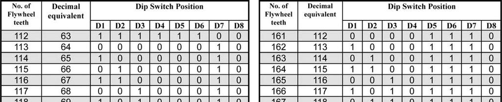
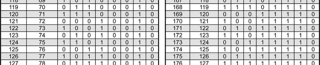
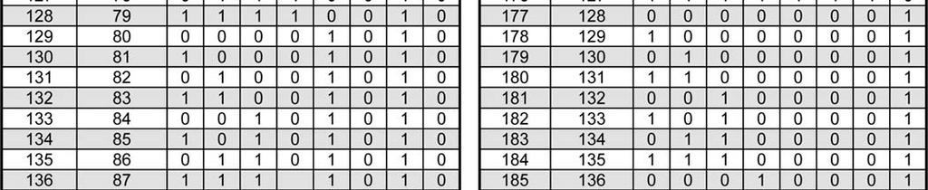
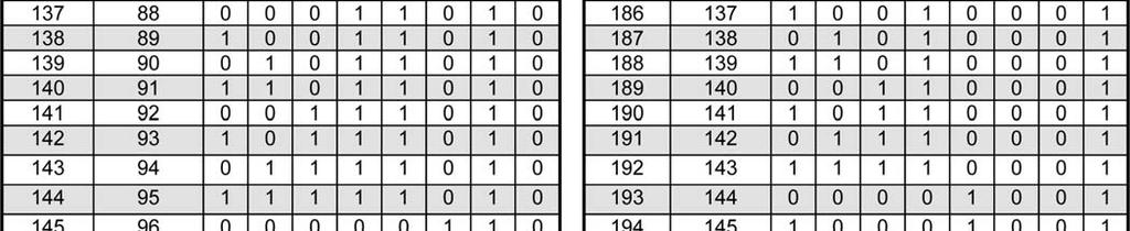
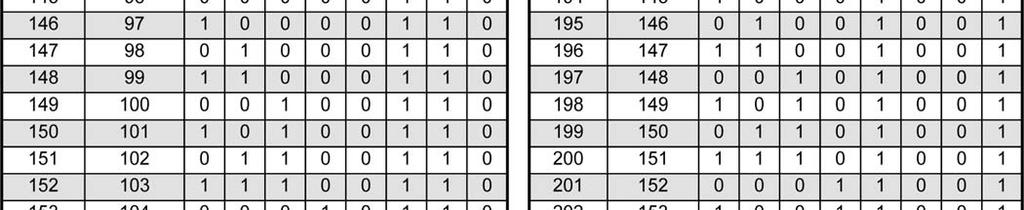
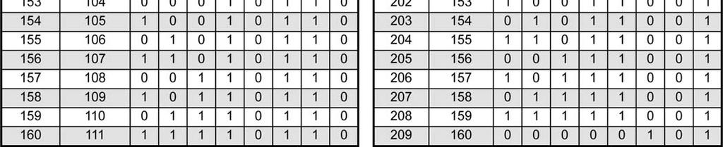
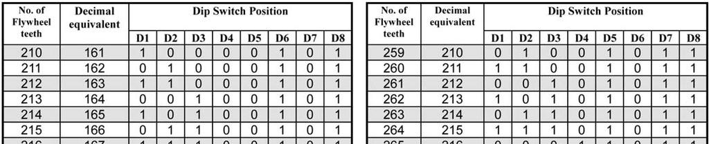
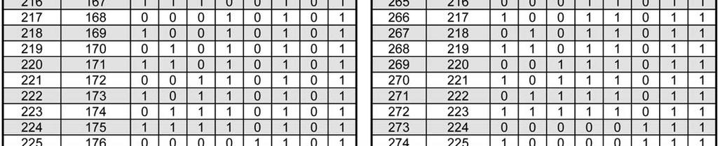
9 Calibration Instructions Magnetic Sensor Driven Models These models have been designed to function with flywheels having 50 to 304 teeth. Any number in this range can be set using the dip switches provided on the back (see Figure 3 - following). For more details, also refer to Table 1 (In the section: Dip Switch Setting Charts, Magnetic Sensor Driven Models). If the number of teeth on the flywheel is known, set the calibration by using a pin to adjust the dip switches (see Figure 3, following). IMPORTANT: DO NOT use a pencil or pen of any type to adjust dip switches. If the pencil breaks while setting the dip positions, graphite can cause a short internally. Leaking ink can do the same. Formula for setting dip switches: Dip switch setting = binary of decimal equivalent. Decimal equivalent = number of flywheel teeth NOTE: Dip switches D1 to D8 will be used for setting calibration. Do not change settings on Dip Switches D9 and D10. For more details refer to Table 1 - Dip Switch Setting for each model type. NOTE: Make sure the engine has a properly functioning and certified governor before attempting this procedure. If the number of teeth on the flywheel is not known, set up a calibrated shop tach to monitor the engine s true RPM. Start the engine, and after an appropriate warm-up period increase to normal running RPM as read on the shop tach. If the dip switch was not set previously, set it now to the position that causes the Murphy tach to read closest to the true RPM
10 Alternator Driven Models The alternator-driven tachometer-series models will operate from 3 to 255 pulses per engine revolution. Most applications will be between 3 and 32 pulses per revolution. Obtain the number of pulses per engine revolution: 1. Determine the number of poles on your alternator. Look for the designation/type in the manufacturer s manual. 2. The Alternator Tachometer Chart (Figure 4 in the section: Pulley Ratios Chart and Alternator Tachometer Chart) lists common alternators and their minimum and maximum pulley ratios. Determine pulley ratio with the following formula: PULLEY RATIO = CRANK SHAFT PULLEY DIAMETER ALTERNATOR PULLEY DIAMETER 3. CHECK that Pulley Ratio falls within the range shown on the Pulley Ratio Chart (Figure 4) for a particular alternator. If ratio falls in the shaded area, the tachometer can be calibrated for the application. 4. To determine the pulses per engine revolution: NUMBER OF POLES x PULLEY RATIO = PULSES PER ENGINE REVOLUTION 2 5. If the Pulses per engine revolution is determined, then set the calibration through selector/dip switches (See Fig. 3 in the section: Calibration Instructions, Magnetic Sensor Driven Models). 6. Formula for setting Dip switches: Decimal equivalent = No. of Pulses will be used for setting calibration Dip switch setting = Binary of decimal equivalent IMPORTANT Dip switches D1 to D8 will be used for setting of calibration. Do not change or disturb settings on Dip Switches D9 and D10. For more details, see Table

11 Pulley Ratios Chart and Alternator Tachometer Chart Figure 4 NOTE: * Although the tach may be calibrated for higher input frequencies in some cases, as shown on the Pulley Ratios Chart, pulley ratios in excess of 5.0 are not recommended nor are they normally used
12 Ignition Driven Models The ignition coil-driven tach series models will operate from 1 to 5 pulses per engine revolution. To obtain the number of pulses per engine revolution: The ATI and ATHI series models have been designed to function from the ignition signal on 2 through 10-cylinder, 4-cycle engines. Set the calibration using the Dip switches. For more details, see the following formula and information in Table 3 (in the section: DIP Switch Setting Charts, Ignition Driven Models). Work the following formulas for your Ignition Coil system: Formula for Setting Dip Switches: Dip switch setting = Binary of decimal equivalent. Decimal equivalent = Number of Pulses per engine revolution. Number of Pulses per engine revolution = Number of engine cylinders 2 For Dip switch settings, please refer Table 3 (in the following section) for ignition speed signals. IMPORTANT: DO NOT use a pencil or pen of any type to adjust dip switches. If the pencil breaks while setting the dip positions, graphite can cause a short internally. Leaking ink can do the same


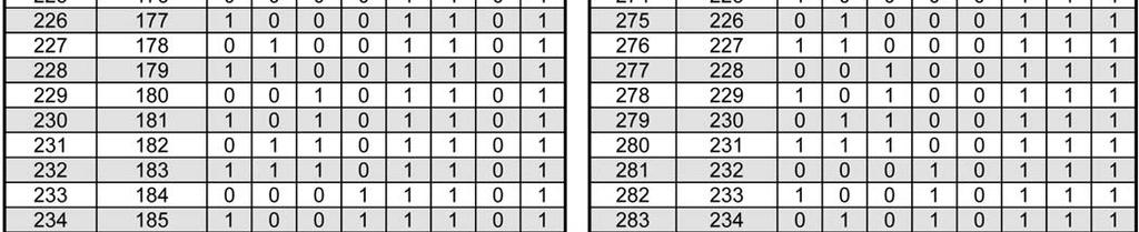
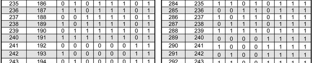
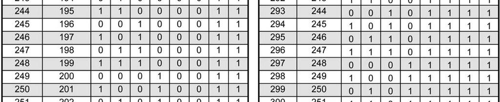
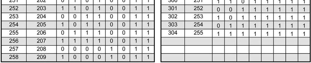
13 Dip Switch Setting Charts Table 1 - Magnetic Sensor Driven Models NOTE In the following table, 1 means ON and 0" means OFF
14
15

16 Table 2 - Alternator Driven Models NOTE: In the following table, 1 means ON and 0" means OFF. NOTE: Switch combinations up to 255 pulses per revolution are not shown as the range of 3 32 pulses per revolution fits most applications. Table 3 - Ignition Driven Models NOTE: Dip switches D4 through D8 are not used and should be set to OFF
17 Potentiometer Fine Adjustment Calibration You can adjust calibration on all models through the fine adjust potentiometer (pot) located on the back side of the housing. NOTE: This option is for fine tuning and not for coarse tuning. The following steps will guide you through the fine adjustment process. 1. Use a duly calibrated optical tach or master tach to determine actual engine RPM. 2. Determine DIP switch settings by calculating and using the table to set the DIP switches provided on the back side of the gauge accordingly. Refer to the preceding calibration instructions. 3. Remove the QC passed sticker to access the fine adjustment hole. 4. Use small flat screw driver (watch maker No. 4) for fine tuning. Make sure the screw driver sits properly in potentiometer slot without touching other parts of the PCB. 5. Rotate the potentiometer such that the reading of the tach matches the actual RPM noted by the master tach. Turning the pot in clockwise direction will increase RPM, while turning the pot in counter-clockwise direction will decrease the RPM. IMPORTANT! The fine adjustment potentiometer can only be turned ¾ of a turn. Be gentle and do not force it. 6. The maximum range for increasing and decreasing the RPM through fine adjustment pot is approximately 400 RPM. 7. If unable to match the reading with the master tach using the method above, then recheck the calculations or change the next level DIP switch setting and repeat the calibration procedure. 8. Once the pointer is adjusted to the desired position, it is recommended to cover the fine adjustment hole to protect it from water entry and other atmospheric effects
18 Specifications Magnetic Sensor Driven Models Power Input: 11-28VDC (70mA 120mA except lamp load) Backlight: 3.4W T-10 wedge base bulb RPM Input Signal Voltage: 1.5Vrms minimum Accuracy: Tachometer: +2% full scale Hourmeter: +0.01% hours, +1 count Temperature Range: -40 o C to +82 o C (no permanent damage shall occur) Dial (Face Plate): 270 o sweep with white numerals (over black background) Bezel: 304 stainless steel for bright and IS 513 E.E.E. CRCA steel for black Scale: RPM Case Material: Plastic Hourmeter Range: hours in 0.1 increments. Alternator Driven and Ignition Driven Models Power Input: 11-28VDC (70mA-120mA except lamp load) Backlight: 3.4W T-10 wedge base bulb RPM Input Signal Voltage: V low: 0.5V max, V high: 8.0V min. Accuracy: Tachometer: +2% full scale Hourmeter: +0.01% hours, +1 count Temperature Range: -40 o C to +82 o C (no permanent damage shall occur) Dial (Face Plate): 270 o sweep with white numerals (over black background) Bezel: 304 stainless steel for bright and IS 513 E.E.E. CRCA steel for black Scale: RPM Case Material: Plastic Hourmeter Range: hours in 0.1 increments
19 MURPHY and the Murphy logo are registered and/or common law trademarks of Murphy Industries, Inc. This document, including textual matter and illustrations, is copyright protected by Murphy Industries, Inc., with all rights reserved. (c) 2011 Murphy Industries, Inc. Other third party product or trade names referenced herein are the property of their respective owners and are used for identification purposes only.
Tachometers and Tach/Hourmeters
 Tachometers and Tach/Hourmeters AT and ATH Series Installation Instructions IMPORTANT! These instructions are specific to tachometer models with a power input operating range of 11-28 VDC and calibration
Tachometers and Tach/Hourmeters AT and ATH Series
 Tachometers and Tach/Hourmeters AT and ATH Series Installation Instructions 00-02-0986 Section 70 IMPORTANT! These instructions are specific to tachometer models with a single calibration push button.
WARNING. Models Magnetic Sensor Tachometer 3000 RPM; pulses 12 VDC
 Tachometer and Tach/Hourmeter Installation Instructions Series: ATS, ATHS, ATA, ATHA, ATHI Please read the following instructions before installing. A visual inspection is recommended before mounting.
Sentry Battery Charger. Installation and Operations Manual Section 75
 Sentry Battery Charger Installation and Operations Manual 00-02-0616 03-03-08 Section 75 In order to consistently bring you the highest quality, full featured products, we reserve the right to change our
INSTALLATION INSTRUCTIONS
 INSTALLATION INSTRUCTIONS WARNING: WARNING: www.altronicinc.com DEVIATION DEVIATION FROM THESE FROM INSTRUCTIONS THESE INSTRUCTIONS MAY LEAD MAY TO LEAD IMPROPER TO IMPROPER OP- ERATION OF ENGINE THE MACHINE
Installation Instructions
 Quick-Mount Visual Instructions for Quick-Mount Visual Instructions 1. Rotate the damper to its failsafe position. If the shaft rotates counterclockwise, mount the CCW side of the actuator out. If it rotates
ESC2301. Universal Electronic Governor Controller Operation Manual
 ESC2301 Universal Electronic Governor Controller Operation Manual *Replaces most Woodward, Barber Colman & Cummins Speed Controls Features Smoke Limit Control, Idle Speed Control, 12V or 24V input Suitable
Installation Instructions
 Quick-Mount Visual Instructions for Mechanical Installation Quick-Mount Visual Instructions 1. Rotate the damper to its failsafe position. If the shaft rotates counterclockwise, mount the CCW side of the
MD10. Engine Controller. Installation and User Manual for the MD10 Engine Controller. Full Version
 MD10 Engine Controller Installation and User Manual for the MD10 Engine Controller. Full Version File: MartinMD10rev1.4.doc May 16, 2002 2 READ MANUAL BEFORE INSTALLING UNIT Receipt of shipment and warranty
DC Variable Speed Drive Panel
 DC Variable Speed Drive Panel Installation, Operation & Maintenance Instruction Manual Bulletin #: CC-IOM-0103-D Manufacturers of Quality Pumps, Controls and Systems ENGINEERED PUMP OPERATIONS 2883 Brighton
EG3000. Generator Electronic Governor Controller Operation Manual
 EG3000 Generator Electronic Governor Controller Operation Manual Smoke Limit Control, Idle Speed Control, suitable for Builtin, Non-Built-in and PT Pump Type Actuator. SP POWERWORLD LTD Willows, Waterside,
CONTROL BOX. Wiring the control box into the vehicle. +12V
 CONTROL BOX Once the display panel is in place, mount the control box within the connecting cable's distance (approximately 3 feet) and secure to the underside of the dashboard. This case does not have
EG1069X. Generator Electronic Governor Controller Operation Manual
 EG1069X Generator Electronic Governor Controller Operation Manual Smoke Limit Controller Compatible with Barber Colman Dyn1-1069X series *Use for reference purpose only and not a genuine Barber Colman
Automatic Transfer Switch FT-10 Network Control Communications Module (CCM-T) Kit
 Kit") Instruction Sheet 10-2004 Automatic Transfer Switch FT-10 Network Control Communications Module (CCM-T) Kit 541 0811 PURPOSE OF KIT A CCM-T is used to monitor and control an automatic transfer switch.
Instruction Sheet 10-2004 Automatic Transfer Switch FT-10 Network Control Communications Module (CCM-T) Kit 541 0811 PURPOSE OF KIT A CCM-T is used to monitor and control an automatic transfer switch.
Lube Level Maintainer
 Lube Level Maintainer Models LM2000/LM2000S Installation Instructions 00-02-0423 Revised 08-12-09 Section 15 In order to consistently bring you the highest quality, full featured products, we reserve the
Guardian Battery Charger Series. Installation and Operations Manual Section 75
 Guardian Battery Charger Series Installation and Operations Manual 00-02-0615 02-29-08 Section 75 In order to consistently bring you the highest quality, full featured products, we reserve the right to
Using the PST-2000 with Peterbilt Trucks. Document Number B
 Using the PST-2000 with Peterbilt Trucks Document Number Every effort has been made to keep the information in this document current and accurate as of the date of publication or revision. However, no
The RPM module will remain in Normal mode by default. It will also return to this mode after settings have been recalled or changed
 Shiftlight Operating Instructions: Setting up your shiftlight: The RPM module requires you to set the turn-on RPM and the number of cylinders. Once these two pieces of information are set, they will not
Service Bulletin No.: DAC Rev 0 Date Issued: 29 June 2017 Title: Removal of OAT/Clock AA Battery Page: 1 of 5
 Title: Removal of OAT/Clock AA Battery Page: 1 of 5 1. ATA Code: 3100 2. Effectivity: All DA20-C1 aircraft with the M803-14V OAT/Clock installed. 3. General: Addresses a magnetic interference issue on
Generator Set Applications FT-10 Network Control Communications Module (CCM-G) Kit
 Kit") Instruction Sheet 10 2004 Generator Set Applications FT-10 Network Control Communications Module (CCM-G) Kit 541 0810 GENERAL INFORMATION This kit contains one Control Communications Module (CCM-G) with
Instruction Sheet 10 2004 Generator Set Applications FT-10 Network Control Communications Module (CCM-G) Kit 541 0810 GENERAL INFORMATION This kit contains one Control Communications Module (CCM-G) with
WARNING. Murphy W-Series Engine Panels General Installation Instructions. Installation Accessories
 Murphy W-Series Engine Panels General Installation Instructions WS-93002N Revised 04-06 Section 30 (00-02-0191) Read the following information before installing. These installation instructions are typical
E.S.P. Embedded Sensing Probes for Motor Brushes
 E.S.P. Embedded Sensing Probes for Motor Brushes 2/13 Installation & Operating Manual MN609 Any trademarks used in this manual are the property of their respective owners. Important: Be sure to check www.baldor.com
Mustang. Installation Manual. Revision 11/16/10
 1967-1968 Mustang Installation Manual Revision 11/16/10 I Table of Contents TABLE OF CONTENTS...II WELCOME TO THE TEAM OF CLASSIC INSTRUMENTS!... III REMOVE ORIGINAL INSTRUMENT PANEL...1 DETERMINE SPEEDOMETER
6 Gauge Box Set IS0333
 Caution 6 Gauge Box Set IS0 Rev. B ecr 882 9/202 Disconnect the battery during installation. Tighten nuts on the back clamp only slightly more than you can tighten with your fingers. Six inch-pounds of
CA 421 Installation Instructions
 CA 421 Installation Instructions PROFESSIONAL INSTALLATION STRONGLY RECOMMENDED Installation Precautions: Roll down window to avoid locking keys in vehicle during installation Avoid mounting components
Table of Contents General Information Specifications Dimensions Programming Instructions Installation Parts List Input Devices
 b Table of Contents General Information 1 Features...1 Specifications 1 Visi-Tach Model Number Description...2 Dimensions 3 Programming Instructions 4 Programming the VT-3........4 Programming the VT-3U...9
Model 616 Rotating Disk Electrode Instruction Manual
 Model 616 Rotating Disk Electrode Instruction Manual 219303 C / 1202 Printed in USA Advanced Measurement Technology, Inc. a/k/a Princeton Applied Research, a subsidiary of AMETEK, Inc. WARRANTY Princeton
GENSET CONTROL MODULE LEVEL 1 A121CM / A241CM. Special logic to re-establish cranking following a false start.
 Technical Data Sheet GENSET CONTROL MODULE LEVEL 1 A121CM / A241CM Features: Models for both 12V and 24V systems. One model for both spark ignition and diesel engines. 5-alarm light outputs with lamp-test
FULL SWEEP STEPPER MOTOR INSTRUMENT KIT INSTRUCTION MANUAL 1969,REDLINE, 2020 SERIES
 FULL SWEEP STEPPER MOTOR INSTRUMENT KIT INSTRUCTION MANUAL 1969,REDLINE, 2020 SERIES REVB071211 INDEX 3-3/8 PROGRAMMABLE SPEEDOMETER 3-3/8 TACHOMETER 2-1/16 GAUGES TEMPERATRURE SENDER PRESSURE SENDER PROGRAMMABLE
Technical Note CTTN #151
 Technical Note CTTN #151 FXM5 Stand Alone Mode with Field Weakening This is pertinent to Mentor II / Quantum III drives Background: This document attempts to outline the procedure on how to setup the FXM5
GENSET CONTROL MODULE A121A / A241A
 Technical Data Sheet GENSET CONTROL MODULE A121A / A241A Features: Models for both 12V and 24V systems. One model for both spark ignition and diesel engines. 4-alarm light outputs with lamp-test provisions.
Tri-Spark Ignition System Installation Triple Cylinder TRI-0001
 Tri-Spark Ignition System Installation Triple Cylinder TRI-0001 There are potentially lethal high voltages produced at the ignition coils and spark plugs, therefore every precaution must be taken to prevent
CONTROL FEATURES AVAILABLE OPTIONS
 Vari Speed A2000 TABLE OF CONTENTS Control Features Options Application Data Operating Condition s Control Ratings Chart Mounting Dimensions Installation and Wiring Typical Wiring Diagram Schematic (Block
Installation Instructions
 Quick-Mount Visual Instructions for Mechanical Installation Quick-Mount Visual Instructions. Rotate the damper to its failsafe position. If the shaft rotates counterclockwise, mount the CCW side of the
INSTALLATION & OPERATION MANUAL
 INSTALLATION & OPERATION MANUAL MODEL T575N TEMPERATURE COMPENSATED TOTALIZER/PRINTER DOC#: MN-T575N SPONSLER, INC. Liquid and Gas Flow Measuring Devices and Controls LBS ON OFF TRUCK TOTALIZER MODEL T575N
Ford Mustang. Installation Manual
 1965 1966 Ford Mustang Installation Manual TABLE OF CONTENTS Welcome from the Team at Classic Instruments! 3 Mounting Gauges in New Bezel 4 3 3/8 Speedometer Wiring 6 3 3/8 Speedometer Wiring Diagram 6
1995 Aerostar/Ranger/Explorer
 95 Aerostar/Ranger/Explorer Section 13-01: Instrument Cluster, Conventional DIAGNOSIS AND TESTING 95 Aerostar/Ranger/Explorer Workshop Manual Pinpoint Tests PINPOINT TEST A: FUEL LEVEL READS INACCURATELY
SE-3SCR-LM MANUAL MOTOR LOAD MANAGER
 3714 Kinnear Place Saskatoon, SK Canada S7P 0A6 Ph: (306) 373-5505 Fx: (306) 374-2245 www.littelfuse.com/relayscontrols SE-3SCR-LM MANUAL MOTOR LOAD MANAGER MARCH 5, 2013 REVISION 4 MOTOR LOAD MANAGER
WARNING. Murphy W-Series Engine Panels General Installation Instructions. Installation Accessories
 Murphy W-Series Engine Panels General Installation Instructions WS-93002N Revised 08-02 Section 30 (00-02-0191) Read the following information before installing. These installation instructions are typical
Operating & Maintenance Instructions Thermobend Elite Range
 Operating & Maintenance Instructions Thermobend Elite Range Table of Contents 1. Setting Up... 2 1.1 Introduction... 2 1.2 Location & Assembly... 4 1.3 Electrical Supply & Connection... 5 1.4 Pneumatic
DISTRIBUTORLESS IGNITION SYSTEM Installation and Adjustment Instructions
 DISTRIBUTORLESS IGNITION SYSTEM Installation and Adjustment Instructions 1.0 INTRODUCTION: Congratulations on your purchase of a Holley Distributorless Ignition System! Holley cannot and will not be responsible
Mustang. Installation Manual
 1967-1968 Mustang Installation Manual I Table of Contents TABLE OF CONTENTS... II WELCOME TO THE TEAM OF CLASSIC INSTRUMENTS!... III REMOVE ORIGINAL INSTRUMENT PANEL... 1 DETERMINE SPEEDOMETER SIGNAL...
RoadRelay 4. Installation Guide
 RoadRelay 4 Installation Guide RoadRelay 4 Installation Guide Bulletin No. 3401767 Revision B Copyright 2002, Cummins Inc. All rights reserved. Cummins Inc. shall not be liable for technical or editorial
2003 Saturn Vue. SATURN 3.0L V6 DOHC - L-Series After VIN & Vue
 TIMING BELT Removal 1. Disconnect negative battery cable. Remove air cleaner assembly. 2. Raise and support vehicle. Remove right front wheel. Remove lower front splash shield. 3. Lower vehicle. Loosen,
6 Gauge Box Set with Programmable Speedometer. Made in the USA. Caution. Speedometer Parts. Tachometer Parts. Fuel Level Gauge Parts.
 6 Gauge Box Set with Programmable Speedometer Caution Disconnect the battery during installation. Tighten nuts on the backclamp only slightly more than you can tighten with your fingers. Six inch-pounds
Altair Electronic Ignition System for
 Altair Electronic System for 3 Cylinder Motorcycles System# AL3 Altair Electronic System for Triumph Trident T150, T150V, T160 X75 Hurricane BSA A75R Rocket 3 Features Fully digital design Compact digital
BSR Magic Box Digital ignition control for 4, 6, or 8 cylinder engines
 BSR BSR Magic Box Digital ignition control for 4, 6, or 8 cylinder engines Features Digital Advance The main feature of the Magic Box is the digital advance that replaces conventional weights and springs.
CA-510a Installation Instructions
 CA-510a Installation Instructions PROFESSIONAL INSTALLATION STRONGLY RECOMMENDED Kit Contents Installation Precautions: Roll down window to avoid locking keys in vehicle during installation Avoid mounting
ATTENTION. Custom Dynamics UTV Turn Signal Kit Installation Instructions
 Custom Dynamics UTV Kit Installation Instructions We thank you for purchasing the Custom Dynamics UTV LED Kit. Our products utilize the latest technology and high quality components to ensure you the most
SB SWITCH CONTROL BOX
 Carson Manufacturing Co., Inc. 5451 North Rural Street Indianapolis, IN 462 Phone: (888) 577-6877 Fax: (317) 254-2667 www.carsonsirens.com SB-008-25 SWITCH CONTROL BOX INSTALLATION AND OPERATING INSTRUCTIONS
The Multi-Fuel Timing Conversion Kit Installation & Setup Instructions
 The Multi-Fuel Timing Conversion Kit Installation & Setup Instructions 1. Remove the flywheel shroud from engine, uninstall the recoil pull start unit from the shroud. 2. Remove the valve cover and the
BOLT-ON AND WELD-ON FLUSH FLOOR SLIDEOUT SYSTEMS OPERATION AND SERVICE MANUAL
 BOLT-ON AND WELD-ON FLUSH FLOOR SLIDEOUT SYSTEMS OPERATION AND SERVICE MANUAL TABLE OF CONTENTS SYSTEM...... Warning........ Description...... Prior to Operation OPERATION... Main Components... Mechanical...
CAUTION: READ INSTRUCTIONS CAREFULLY BEFORE STARTING INSTALLATION
 V-Twin MFG. VT No. 32-9500 V-TECH 1 IGNITION KIT, SINGLE FIRE FITS EV SHOVEL, XL THRU 1997 VT No. 32-9503 V-TECH 1 IGNITION KIT, SINGLE FIRE FITS EV, SHOVEL, XL, WITH COIL AND WIRES This is a custom application
EG1065X. Compatible with Barber Colman* Dyn1-1065X series * Use for reference purpose only and not a genuine Barber Colman product.
 EG1065X Generator Electronic Governor Controller Operation Manual Compatible with Barber Colman* Dyn1-1065X series * Use for reference purpose only and not a genuine Barber Colman product. Headquarters
Condensed Version of Operator s Manual For The VI/VP700 Series Flowmeter and VI800 Series Flowmeter
 Condensed Version of Operator s Manual For The VI/VP700 Series Flowmeter and VI800 Series Flowmeter Warranty Agreement J-TEC Associates warrants this product to be in good working order for a period of
Tattletale Annunciators and Magnetic Switches
 Tattletale Annunciators and Magnetic Switches Tattletale annunciators and magnetic switches are the nerve centers that translate Swichgage contact operations into decisions and operate the alarm or shutdown
PHOENIX TACHOMETER WITH OLED DISPLAY
 PHOENIX TACHOMETER WITH OLED DISPLAY REV A0031418 PROGRAMMABLE TACHOMETER WIRING Standalone tachometers with AMP plugs are incandescent perimeter, backlit or LED backlit. Incandescent bulbs will be in
The GearMaster II. Making Shifting a Breeze
 The GearMaster II Making Shifting a Breeze Congratulations on your purchase of the GearMaster, the world s first and only Gear Availability and Synchronization Indicator! You will find that the GearMaster
P200 P/I Transducer. Installation, Operation, and Maintenance Instructions INTRODUCTION
 INTRODUCTION Scope This manual provides instructions for the installation, adjustment, maintenance, and parts ordering of the P200 Pneumatic-to-Current P/I Transducer. Due to its over-engineered design,
LIPPERTCOMPONENTS, INC.
 LIPPERTCOMPONENTS, INC. SCHWINTEK INWALL SLIDEOUT SYSTEM OPERATION AND SERVICE MANUAL Contents I. Controls 1-1 System components 1 1-1A versions C1 & C2 2 1-2 Motor wiring harness connections 3 1-3 Extend
IMPORTANT! READ BEFORE INSTALLING!
 1360 Redwood Way, Suite A Petaluma, CA. 94954 TEL: (707) 763-7799 Toll free in the USA (800) 767-9543 FAX (707) 763-2631 www.xandexsemi.com EMAIL: info@xandex.com Instructions for Xandex Pneumatic Controller
Sprayer Control. Manual for SprayLink Cable Installations. Tank. Jet Agitator. Agitator Valve. Diaphragm Pump. Pressure Transducer.
 Sprayer Control Plumbing & Installation Manual for SprayLink Cable Installations Tank Jet Tank Shut-Off Diaphragm Pump Electric Ball s Transducer Strainer Relief Regulating Copyrights 2012 TeeJet Technologies.
INSTALLATION GUIDE Chevrolet Digital Dash Panel Part Number: DP6003 Year Series:
 INSTALLATION GUIDE Chevrolet Digital Dash Panel Part Number: DP6003 Year Series: 1967-1972 * Disconnect the battery before attempting any electrical work on your vehicle. * KIT COMPONENTS One (1) Digital
Crankshaft Position Sensor
 1 of 7 1 GM Bonneville/Eighty Eight/LeSabre 1986-1999 Crankshaft Position Sensor OPERATION TESTING REMOVAL & INSTALLATION See Figures 1, 2 and 3 The dual Crankshaft Position (CKP) sensor is mounted to
CM52 Network Protector with Arc Flash Reduction Module
 Contents Description Page 1: General.............................. 2 2: Maintenance Mode Settings.............. 2 3: Arming Maintenance Mode.............. 2 4: Remote Indicator....................... 2
Siemens VDO Phone:
 Siemens http://sso-usa.siemensvdo.com/ Phone: 1-800-265-1818 !" # %]]! "&]] # ( ]] # (%]]!!( # ]] BUT4_d GXYdU4_d ## ($]] If you have any doubts, please contact your dealer or Instruments at 1-800-265-1818.
HD 7700 Setup & Operator Manual
 HD 7700 Setup & Operator Manual Issue 1 December, 01 Performance Design Inc. The Heavy Duty Ultima (HD 7700) electric punch has been designed to punch most any job that may pass through your bindery or
REMOVAL & INSTALLATION
 REMOVAL & INSTALLATION CAUTION: This application is an interference engine. Do not rotate camshaft or crankshaft when timing belt is removed, or engine damage may occur. TIMING BELT Removal 1. Disconnect
Rheometer Calibration Fixture Instruction Manual Model 280 & 286
 Rheometer Calibration Fixture Instruction Manual Model 280 & 286 Instruction Manual Part No. 204210 Revision B Copyright 2009 Fann Instrument Company Houston, Texas, U.S.A. All rights reserved. No part
Solid-State Compass with GPS Receiver
 Owner s Guide & Installation Instructions Solid-State Compass with GPS Receiver Model GH2183 Record the serial number found on the sensor. Serial No. Date of Purchase 17-489-01 rev. 01 04/22/08 1 WARNING
ELECTRONIC ENGINE CONTROLS. (Model 6525)
") ELECTRONIC ENGINE CONTROLS (Model 6525) INSTALLATION MANUAL February 2012 ELECTRONIC ENGINE CONTROLS INSTALLATION INSTRUCTIONS Table of Contents 1. GENERAL INFORMATION... 1-1 2. SYSTEM COMPONENTS... 2-1
ELECTRONIC ENGINE CONTROLS (Model 6525) INSTALLATION MANUAL February 2012 ELECTRONIC ENGINE CONTROLS INSTALLATION INSTRUCTIONS Table of Contents 1. GENERAL INFORMATION... 1-1 2. SYSTEM COMPONENTS... 2-1
This manual (part # ) applies to the following product part numbers:
 applies to the following product part numbers:") Installation / Troubleshooting Manual TWINSCAN 3, GAS AND DIESEL TACH (New LCD) This manual (part # 1000-158-01) applies to the following product part numbers: 1) 3TB013 2) 3TB013U 3) 3TB014 4) 3TB014M
Installation / Troubleshooting Manual TWINSCAN 3, GAS AND DIESEL TACH (New LCD) This manual (part # 1000-158-01) applies to the following product part numbers: 1) 3TB013 2) 3TB013U 3) 3TB014 4) 3TB014M
Classic Instruments. Installation Manual
 Classic Instruments Installation Manual TABLE OF CONTENTS Welcome from the Team at Classic Instruments! 3 Mounting Gauges 4 4 Speedometer Wiring 5 4 Speedometer Wiring Diagram 5 16 Pulse Signal Generator
SECTION 6Y ENGINE ELECTRICAL. CONTENTS OF THlS SECTION. Page Ignition System " 6Y-1 Specifications 6Y Passenger Shop Manual IGNITION SYSTEM
 SECTION 6Y ENGINE ELECTRICAL CONTENTS OF THlS SECTION Page Ignition System " 6Y-1 Specifications 6Y-5 Charging System 1961 Passenger Shop Manual Starting System 1961 Passenger Shop Manual IGNITION SYSTEM
5001TCP SPEED CONTROLLER
 INSTALLATION AND SETTING UP MANUAL 5001TCP SPEED CONTROLLER WARNING Disconnect all incoming power before working on this equipment. Follow power lockout procedures. Use extreme caution around electrical
LAMP BULB SERVICE TABLE OF CONTENTS
 8L - 6 LAMPS XJ LAMP BULB SERVICE TABLE OF CONTENTS AND FRONT POSITION LAMP BULB...6 SIDE REPEATER LAMP BULB...6 AND FRONT POSITION LAMP BULB REAR FOG LAMP BULB...7 LICENSE PLATE LAMP BULB...7 (3) Pull
5001TCP SPEED CONTROLLER
 VARIABLE SPEED DRIVE CONTROLLER INSTALLATION AND SETTING UP MANUAL 5001TCP SPEED CONTROLLER With PC101 Torque Limit Control WARNING Disconnect all incoming power before working on this equipment. Follow
Model A Turn Signal Kit Installation Guide
 Model A Turn Signal Kit Installation Guide Creative Connections, Inc. Consumer Hot Line: 888-471-LOGO 770-476-7322 In Atlanta, GA http://www.logolites.com P/N: 100-005/K 2008 Creative Connections, Inc.
MAGPOWR Spyder-Plus-S1 Tension Control
 MAGPOWR TENSION CONTROL MAGPOWR Spyder-Plus-S1 Tension Control Instruction Manual Figure 1 EN MI 850A351 1 A COPYRIGHT All of the information herein is the exclusive proprietary property of Maxcess International,
RU SERIES UPGRADE TempAssure Compatible
 RU SERIES UPGRADE TempAssure Compatible This converter section has been designed as a converter section replacement in the following MagneTek or Parallax Power Supply series products and models with DC
INSTALLATION GUIDE Six Gauge Universal Digital Dash Panel Part Number: DP10002
 Made in America Lifetime Guarantee Thank you for purchasing this digital dash panel from Intellitronix. We value our customers! INSTALLATION GUIDE Six Gauge Universal Digital Dash Panel Part Number: DP10002
Classic Instruments SN74Z. Installation Manual
 Classic Instruments SN74Z Installation Manual Table of Contents Welcome from the Team at Classic Instruments!... 3 Before You Get Started... 4 Speedometer Application... 4 Connecting the SN74Z... 4 SN74Z
Southwest Windpower Instruction Sheet AIR-X Circuit Replacement Kit
 Southwest Windpower Instruction Sheet AIR-X Circuit Replacement Kit Tools Required 5 / 32 Hex key 5 / 16 Hex key 7 / 64 Hex key Standard screwdriver Pair of external snap ring pliers Rubber mallet Hammer
GM Cavalier/Sunfire Repair Guide
 . 1 of 8 8/16/2009 4:20 PM GM Cavalier/Sunfire 1995-2000 Repair Guide Headlights REMOVAL & INSTALLATION AIMING THE HEADLIGHTS REMOVAL & INSTALLATION See Figures 1, 2, 3, 4, 5, 6, 7 and 8 Fig. Fig. 1: Pry
FITTING INSTRUCTIONS
 FITTING INSTRUCTIONS Read carefully all sections before proceeding with any fitting OPTRONIC CLASSIC COLLECTION PMC 50 Requires FK fitting kit sold separately Thank you for purchasing this Lumenition Ignition
EDG6000 Electronic Digital Governor
 INTRODUCTION GAC s digital governor is designed to regulate engine speed on diesel and gaseous fueled engines. When paired with a GAC actuator the EDG is a suitable upgrade for any mechanical governor
Commander IS0128 ISO128E ECR# /04. Tachometer/ Engine Hourmeter
 Commander Tachometer/ Engine Hourmeter Analog Tachometer Digitally displays Hours Engine Has Been Run Fuel Level Other Features if Available: Fuel anagement Fuel Flow in GPH or LPH Total or Trip Fuel Used
3 Channel Remote Start / Keyless Entry System Installation Instructions
 Model AA-RS5CS Installation Manual 3 Channel Remote Start / Keyless Entry System Installation Instructions This Unit Is Intended For Installation In Vehicles With 12 Volt Negative Ground Electrical Systems,
Technical Sheet on Sprint Tachometers and MSD Ignition Systems. How to Install a Sprint Tachometer With a MSD 6A Ignition System
 Technical Sheet on Sprint Tachometers and MSD Ignition Systems How to Install a Sprint Tachometer With a MSD 6A Ignition System Step 1: Wiring Procedures Sprint Tachometers are voltage-triggered tachometers
Model 579 Curtain Machine Manual. General Information. Unpacking:
 Model 579 Curtain Machine Manual. General Information The Model 579 curtain machine is designed for use with most light duty commercial and residential drapery tracks. The 579 curtain machine is designed
# and # FAST Fuel System Kits
 1 INSTRUCTIONS #307500 and #307501 Fuel System Kits Thank you for choosing products; we are proud to be your manufacturer of choice. Please read this instruction sheet carefully before beginning the installation.
MAINTENANCE INFORMATION ====================
 CHAPTER 1 MAINTENANCE INFORMATION ==================== C O N T E N T S TEST EQUIPMENT REQUIRED SECTION 1 Page 3 FAULT FINDING & SERVICING NOTES SECTION 2 Page 3 VOLTAGE CHECKS WITH NO VALVE UNDER TEST
Installation for L1100, L1200, L1200N Series Liquid Level Switches and DVU150, DVU175, and DVU2105/2115/2120 Series Dump Valves. GENERAL INFORMATION
 Installation for L1100, L1200, Series Liquid Level Switches and DVU150, DVU175, and DVU2105/2115/2120 Series Dump Valves. A =1-1/2 NPT B =2 NPT Meets NACE standard MR-01-75 for direct exposure to H2 S
DISPLAYS: Revolution counters and Speedometers
 DISPLAYS: Revolution counters Revolution counters MOTOMETER revolution counters are equipped with a moving coil measuring unit that shows the exact engine speed. The use of revolution counters is either
PowerView PV380-R2 Mechanical Configuration
 PowerView PV380-R2 Mechanical Configuration Operations Manual *Products covered in this document comply with European Council electromagnetic compatibility directive 2004/108/EC and electrical safety directive
AEROMOTIVE Part # Generic Fuel System Kit INSTALLATION INSTRUCTIONS
 AEROMOTIVE Part # 17126 Generic Fuel System Kit INSTALLATION INSTRUCTIONS CAUTION: Installation of this product requires detailed knowledge of automotive systems and repair procedures. We recommend that
INDEX Section Page Number Remarks
 INDEX Section Page Number Remarks Synchronous Alternators 2 4 General Fault Finding Capacitors 5 6 Fault Finding & Testing Diodes,Varistors, EMC capacitors & Recifiers 7 10 Fault Finding & Testing Rotors
Installation Instructions For The O.CT S4 Boost Gauge
 Installation Instructions For The O.CT S4 Boost Gauge The ultimate power display FROM AND Stratmosphere 28 Boulder Creek Drive Rush, NY 14543 585-533-1777 O.CT Tuning Oberscheider O.CT-Tuning, Reichsstr.
INSTALLATION GUIDE. Dynojet Research 2191 Mendenhall Drive Suite 105, North Las Vegas NV,
 INSTALLATION GUIDE www.dynojetwb2.com Dynojet Research 2191 Mendenhall Drive Suite 105, North Las Vegas NV, 89081 1-800-992-4993 2008 Dynojet Research, Inc. All Rights Reserved. Wideband 2 Installation
EB Conveyor Maintenance Guide
 EB Conveyor Maintenance Guide EN-0037 Rev A EB Conveyor Maintenance Guide www.qdraw.com Table of Contents Overview Page 3 Exploded View Of A Standard EB Conveyor Page 4 Preventative Maintenance Page 5