Navitas Vehicle Systems Ltd
|
|
|
- Stewart Thornton
- 5 years ago
- Views:
Transcription


1 Navitas Vehicle Systems Ltd CTL Installation & Troubleshooting Manual 500 Dotzert Crt. Waterloo, ON N2L 6A7 Phone: Fax:
2 Table of Contents Hardware Installation... 2 Throttle... 3 Typical Wiring Installation... 5 Main Contactor... 6 Forward/Reverse Contactors... 6 Keyswitch... 6 Wiring... 7 Wiring: Series Motors... 8 Basic Wiring Configuration... 8 KSI Wiring... 8 Forward / Reverse Wiring (with standard power wiring)... 9 Plug Braking... 9 Freewheeling (wiring to inhibit plug braking)... 9 Forward/Reverse Wiring Power wiring for reversing with 4 x SPST contactors Throttle Pot Wiring Pots for Twist Grip Throttles Reduced speed operation Installation Troubleshooting Maintenance & Adjustment OPERATIONAL NOTES IN-VEHICLE DIAGNOSTIC TESTS BENCH TESTING FEATURES and FUNCTIONS GLOSSARY... 29
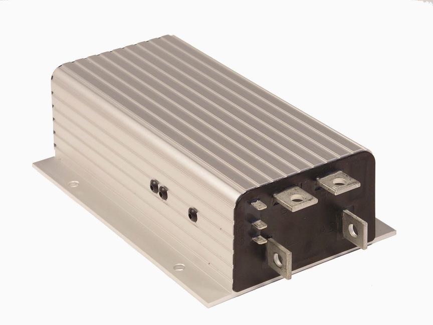
3 Hardware Installation Controller The controller may be oriented in any position, but the location should be carefully chosen to keep the controller as clean and dry as possible. If this is not possible, a cover should be used to deflect dirt and water splash. The controller should be fastened with four screws to a clean dry flat metal surface that provides an adequate heat sink. The mounting surface is an integral part of the overall heat sinking of the controller and affects the ability to dissipate heat. The case outline and mounting hole dimensions are shown below. If your controller is an adjustable model, be sure to mount it so as to allow access to the adjustment screws. Although not usually necessary, a thermal joint compound can be used to improve heat conduction from the case to the mounting surface. 2

4 Throttle The standard controller throttle input is 0-5k. CTL potboxes are designed to match this input. Some of these potboxes have a built in microswitch, eliminating the need to install a separate pedal actuate d microswitch. Any potbox that provides a nominal 0-5k output (controller output begins at 300ohms, full output is 4400 ohms) will work with the standard throttle input. After the chosen potbox has been mounted, operation of the pot can be tested by measuring the resistance between the two wires with an 3
5 ohm meter. With the pedal not applied, the resistance should be less than 50 ohms. As the pedal is applied, the resistance should rise smoothly until it reaches a value between 4500 and 5500 ohms. Values below 4500 ohms may cause a reduction in efficiency and top speed. Values above 7000 ohms indicate a defective pot box and will cause controller shutdown. The AC-NM3V305L or 407L, electronic throttle manufactured by Hardellet, is designed for 24-36V systems, and can be used with any CTL2000 controller having the 0-5V throttle input option. 4
6 Other Hardware The recommended hardware for a typical CTL2000 controller installation is shown below. Contactors should be mounted in a clean dry location. If unavailable, a cover should be used to deflect dirt and water splash. The precharge resistor connected to the main contactor and the coil suppression diodes connected to the main contactor and to the forward/reverse contactors, are somewhat delicate components. Care should be taken to prevent damage to them during installation. Typical Wiring Installation 5
7 Main Contactor Most applications use a main contactor in series with the battery positive (B+) cable to disconnect all power when the system is turned off, as shown. A heavy duty single pole, single throw (SPST) contactor with silver alloy contacts is recommended such as an Albright SW80 or SW180 (Available from Navitas Technologies). A coil suppression diode should be used on the contactor coil. The rapid charging of the controller s internal filter capacitors causes a high inrush current to flow briefly when the contactor closes. To extend contact life, a precharge resistor is recommended; the resistor precharges the capacitors and reduces the inrush current through the contactors. If an inexpensive can type solenoid is used, the resistor is mandatory to prevent contact welding. Forward/Reverse Contactors The forward/reverse contactor coils must match the vehicle s battery voltage. Use of two single pole, double throw (2xSPDT) contactors is recommended. Although inexpensive can type solenoids can be used, their ratings are typically not sufficient for long life. Changeover contactor sets such as Albright DC88 and SW182 (available from Navitas Technologies) are therefore recommended. Forward/Reverse contactors coils can be operated by any type of single-pole, double throw (SPDT) center-off switch capable of switching the coil current. Toggle or rocker switches are generally used. If your controller has the optional high pedal disable (HPD) feature and you plan to wire it for freewheeling, the best switch to use is a double pole, double throw (DPDT) hesitation switch - a toggle switch with a mechanism that forces it to stop in the center (neutral) position before going into the opposite direction. If a standard switch is moved quickly from one direction to the other, it may not be in neutral long enough to actuate HPD, and the motor will plug brake instead of freewheeling. The switch must be in neutral for several milliseconds to actuate HPD. Keyswitch The vehicle should have a master on/off switch to turn the system off when not in use. A keyswitch is typically for this purpose. 6
 vinyl insulated stranded wire is recommended.")

8 Wiring Connections: Low Current Three ¼ push on terminals are provided for the low current connections to the KSI and throttle inputs. For the control wiring, 0.75mm (#18 awg) vinyl insulated stranded wire is recommended. Connections: High Current Four tin-plated solid copper bus bars are provided for the high current connections to the battery and motor: M- output to motor field B- negative connection to battery B+ positive connection to battery and to motor armature A2 plug diode to motor armature The cables used for the battery and motor connections must be heavy enough to carry the high current required. A minimum size of 25mm2 (#4 awg) is recommended. Rubber insulated welding cable is convenient to work with because of flexibility. Connections to the controller bus bars should be made with lugs suitable for the cable used, fastened by M8 (5/16 ) bolts and nuts. When tightening the bolts, two opposing wrenches should be used. Failure to use the double wrench technique could cause undue strain to be placed on the internal connections, and could also result in cracked seals around the bus bars. 7
9 Wiring: Series Motors Below is a schematic of the configuration shown previously (typical wiring). Wired this way, the vehicle will plug brake if the direction is changed with the vehicle moving and the throttle applied. Reversing is accomplished via two single-pole, double throw (2 x SPDT) contactors. Coil suppression diodes should be used on the main and forward / reverse contactors. Basic Wiring Configuration KSI Wiring The keyswitch input (KSI) circuit includes input from the keyswitch from the various interlocks. The controller KSI is used to turn the controller on and off. KSI is turned on by connecting it to battery B+. Any positive voltage greater than about 8 volts will turn on the controller, but usually the full vehicle battery voltage is used. KSI draws only a very small current (a few ma) In its simplest form, KSI is operated by a keyswitch that turns the vehicle off and prevents unauthorized use. The keyswitch should also turn off the main contactor and the forward / reverse contactors. This 8
10 will act as a safety feature by removing power from the motor control system when the keyswitch is turned off. Interlocks (seat switches, battery charger interlocks, etc.) should be wired in series so that they turn off the controller KSI and the contactors. Forward / Reverse Wiring (with standard power wiring) These forward / reverse wiring schemes assume the standard power wiring (shown by the heavy lines below). Some vehicles, especially those previously using older, resistor-type controllers, may reverse the motor armature rather than the field winding. Be careful if you are replacing this type of controller. When using the CTL controller, it is essential that the field be reversed and that the armature be connected directly to the controller s B+ and A2 terminals, because the plug diode inside is connected to these terminals. Plug Braking The standard forward/reverse control wiring (shown by the light lines below) provides plug braking. The forward / reverse switch should be in the positive feed to the contactor coils so that they can be turned off the keyswitch, interlocks and pedal microswitch. The coil for one of the contactor or the other is energized to select the direction required. Freewheeling (wiring to inhibit plug braking) If your controller has the HPD option, this feature can be used to inhibit plug braking by briefly turning off the controller s KSI when the forward/reverse switch goes through neutral. As shown below another set of contacts is added on the forward/reverse switch. Therefore, a double pole, double throw (DPDT) center-off switch must be used for this setup. A hesitation switch is recommended, to ensure the switch is in neutral long enough to actuate HPD and inhibit plug braking. Plug braking can be reactivated during freewheeling by releasing the throttle and reapplying it. 9
11 Forward/Reverse Wiring (with alternate power wiring) The basic wiring scheme below shows reversing via two single pole, double throw (2xSPDT) contactors. Your vehicle may be configured for different type of reversing. Two alternative power wiring schemes are described below reversing with four single pole, single throw (4 x SPST) contactors, and reversing mechanically rather than electrically. Power wiring for reversing with 4 x SPST contactors It is possible to use four single pole, single throw (4 x SPST) contactors, wired as shown below. However, this configuration has the disadvantage that any one of the contactors sticks closed, the motor field is effectively shorted out in one drive direction. The motor will not turn on and it may be damaged if operated like this for long. Other disadvantages are that four, rather than two, contactors must be mounted and wired, and that the coils draw twice as much power. 10
12 The control wiring options for the 4 x SPST contactors are the same as for the 2 x SPDT contactors. Power wiring for mechanical reversing switch (golf car type) As shown below, this type of switch mechanically interchanges the two motor field cables by rotating a movable contact bar. The configuration shown is typical; many variations are in use. Throttle Pot Wiring Standard potbox wiring If the throttle input to the controller is from a CTL potbox or foot pedal, the wiring is simple; just connect the two wires of the potbox / footpedal cable to the two push on terminals of the controller, as shown in the diagram below. It doesn t matter which wire goes on which terminal. The wires can be extended as required. Any suitable potentiometer of 5 k nominal resistance will work with the standard throttle input of the CTL controllers. As shown in the diagram below, connection should be made to the wiper and to the one outer terminal of the pot so that resistance increases as the accelerator is applied. Pots for Twist Grip Throttles Twist grip throttles either twist in only one direction (and are used only for acceleration) or they twist both ways (and are also used for reversing, by means of micro-switches that select a direction contactor) For twist grips that twist in only one direction, the controller throttle input can be from a 5k pot as shown above. For twist grips that twist both ways, a pot capable of going from zero in neutral to 5k in each direction can be used. A mechanism can be designed to make a standard pot turn in the same direction regardless of which direction the twist grip is turned. Alternately, a 4-terminal, 11
13 center-tapped 10k pot can be coupled directly to the twist grip, as shown. A third method of accommodating bi-directional twist grip throttles uses a standard potentiometer and a controller with a nonstandard throttle input. As shown a standard 20k pot is used with its end terminals wired together. The resistance goes from 5k at neutral to zero at the extremes the opposite of the standard throttle input configuration. 12
14 Reduced speed operation Vehicle top speed can be easily limited for safety or other reasons. A single resistor connected in parallel with the throttle pot will reduce maximum speed according to its resistance value, as shown. Use of a variable resistor makes adjustment of maximum speed easier. With a switch, speed can be limited in reverse only, or the speed reduction can be switched off for example, to allow authorized personnel to run the vehicle outdoors as full speed. The speed reduction shown in the curve is approximate. The actual vehicle top speed will depend on the motor characteristics and the vehicle load. You should determine by experiment the proper resistor value to give the desired speed reduction. (Note: with reduced speed operation, only top speed is reduced; full power is maintained for starting at low speeds. 13
15 Electronic Throttle Wiring Navitas Electronic throttle, AC-NM3V305 and AC-NM3V407 throttles are wired as shown below. This requires a controller with the optional 0-5V throttle input. 14
16 Wiring: PM Motors Wiring for controllers in vehicles with permanent magnet motors is the same as in those with series motors, except for the forward/reverse circuit. PM Motors have only two terminals: the armature brushes. The magnetic field is provided by the permanent magnets and cannot be reversed; instead, the motor is reversed by interchanging the armature leads. The PM motor must be connected, via the forward/reverse circuitry, to the controller s B+ and M- bus bars. If your controller is designed for use with either series or PM motors it will have an A2 bus bar, which you should leave unconnected. If your controller is designed for use only with PM motors, it will have no A2 bus bar. Basic PM motor wiring using two single-pole, double throw (2xSPDT) contactors is shown below. Note that when the forward/reverse switch is in the neutral position, neither of the direction contactors is operated and the motor is shorted. This will produce sudden braking if neutral is selected while the vehicle is moving, or if the motor is reversed while the vehicle is moving. The motor acts as a generator and will effectively be shorted out by the freewheel diode inside the controller. The faster the vehicle is moving when the motor is shorted out, the more violent the effect of the sudden braking will be. If violent braking is not acceptable for your application, use one of the wiring schemes described below to allow the motor to freewheel in neutral or whenever the pedal is released. However, note that sudden braking will still occur if the opposite direction is selected and the pedal is re-applied while the vehicle is still moving. 15
17 Basic Wiring for PM Motors A partial solution is to arrange four single pole, single throw (4 x SPST) contactors to open the motor circuit whenever the pedal is released. This arrangement, as shown, causes the vehicle to freewheel in neutral or whenever the pedal is released. The drawback to this is that if one of the contactors sticks closed, the controller s output is shorted and the controller may be damaged. For this reason, we do not recommend the 4 contactor arrangement although it is widely used. 16
18 A better approved is to reverse the motor by the two single pole double throw contactors. A third contactor opens the motor circuit in neutral or when the pedal is released, allowing the motor to freewheel. If you prefer dynamic braking to freewheeling, you can install a dynamic braking resistor. The motor generates power in slowing down the vehicle; the dynamic braking resistor dissipates this power as heat. The amount of braking torque is determined by the resistance and is proportional to the vehicle s speed. The resistor gets hot and must be sized and mounted accordingly. Note: The size of the motor and the amount of braking desired are factors in determining the appropriate dynamic braking resistor. The N.O. and N.C. contacts of the forward/reverse contactors must be wired as shown or this scheme will not work. Note that in all the PM motor wiring schemes shown, the forward/reverse switch is DPDT center-off. In addition to operating the forward/reverse contactors, the switch turns on the controller s KSI and main contactor when forward or reverse is selected. By turning off the KSI in the neutral position, the controller s HPD feature will inhibit the controller output if the forward reverse switch is changed with the pedal depressed. While this will not prevent the braking effect of reversing direction with the vehicle moving, it will at least keep the motor from being driven in the opposite direction. Installation Troubleshooting The following checkout procedure should be completed before operating the vehicle. IF a step does not test correctly, use the troubleshooting guide to identify the problem. 17
19 Safety Precautions: Put the vehicle on blocks to get the drive wheels off the ground before beginning these tests. Don t let anyone stand in front of or behind the vehicle. Make sure the keyswitch is off and the vehicle is in neutral before starting. Wear safety glasses, safety boots and use well insulated tools. A. Connect the battery. Use a voltmeter to verify that the proper voltage and polarity appears at the B+ and B- terminals. B. Check the voltage at the controller B+ and B- bus bars. If your system has a pre-charge resistor in parallel with the main contactor, you should see approximately 90% of the full battery voltage. If your system does not have a resistor, temporarily connect one (100 to 200 ohms, 5 watts or a 100 watt light bulb). The voltage at the controller should rise to approximately 90% of the full battery voltage. C. If A and B do not check out, troubleshoot the wiring connections. Do not turn on the keyswitch until the trouble is corrected and A and B check out. D. With the forward/reverse switch in neutral, turn on the keyswitch. If the motor runs without the throttle being applied, turn the keyswitch off and recheck the wiring. If the motor des not run without the throttle applied, proceed with the checkout. Select a direction and slowly apply the throttle; the motor should now respond. E. Look to see which direction the wheels are turning. If the wheels are going the wrong way, turn everything off and interchange the motor field connections. F. If you have HPD, check it next. Turn off the keyswitch and direction switch. Apply the throttle, turn the keyswitch on, and then select a direction. The motor should not run. Release the throttle and re-apply it the motor should now run. If the motor runs before you release the throttle, recheck the wiring. G. Take the vehicle off the blocks and drive it in a clear area. It should have smooth acceleration and good top speed. H. On vehicles that are intended to plug brake, test the plug braking by driving forward at moderate speed and shifting into reverse without letting up on the throttle. The vehicle should smoothly brake to a stop and accelerate in reverse. I. On vehicles that are intended to have plug braking inhibited, verify that the maneuver in H produces freewheel coasting. 18
20 Maintenance & Adjustment Controller CTL Controllers require minimal maintenance if properly installed. The controllers are sealed and thus are not field serviceable. Maintenance It is recommended that the following 2 steps be performed occasionally. First remove power by disconnecting the battery and discharge the capacitors in the controller (with a light bulb or a 2-10 ohm, 25W resistor connected for a few seconds across B+ and B-) 1. Make sure the electrical connections to the controller and to the motor contactors, etc., are tight. When checking the controller bus bar connections for tightness, use two opposing wrenches. This double-wrench technique will help avoid putting stress on the bus bars, which could crack the seals. Always use insulated wrenches 2. Inspect all seals at the front and back of the controller. If necessary, use a moist rag to wipe these areas clean enough so that you can see the seal. Look for cracks or other signs of seal damage. 3. If the seals are intact, clean the controller by either washing it off or by wiping it clean with a moist rag. Power must not be reapplied to the controller until the terminal area is completely dry. 4. If the seals have been damaged, there are several possible causes. Perhaps the double wrench technique was not used when the cables were installed. Perhaps the vehicle s environment requires that the controller be better protected: either by mounting it in a different location, or by installing a protective cover. 5. Damaged seals can lead to faulty operation. WE strongly recommend replacing controllers that have faulty seals. Adjustment On some models, the plug braking current and acceleration rate settings are adjustable. On these adjustable controllers, the adjustment pots are located as shown. Use the following adjustment procedure. The keyswitch should be off during adjustment. 1. Remove the socket head screw (1/8 allen) for the adjustment you want to make. 19

21 2. Adjust the internal potentiometer using a small insulated screw driver. 3. Replace the socket head screw and the nylon seal washer. To prevent stripping, do not over-tighten. Some behaviors that may seem to suggest controller malfunction do not, in fact, indicate a problem but rather are typical of normal operation. Before undertaking the diagnostic tests, check to see whether your problem is addressed in the first section, Operational Notes. The diagnostic tests are designed to enable you to determine whether the trouble is in the controller or in some other part of the motor control circuitry. The controllers themselves are sealed and not field serviceable; contact Navitas Technologies for technical service. The diagnostic section provides enough detail to enable you to track circuitry problems to their source and repair them. Finally, the bench tests will allow you to confirm controller operation in a simple, low-power test configuration. Bench testing is primarily intended for checking out a number of controllers on a regular basis. OPERATIONAL NOTES Noise Controller operation is normally silent. An exception is that a 1 khz tone may be heard during plug braking. This noise is normal and indicates that plugging is taking place. The noise will stop when plug braking stops. Inability of Vehicle to Plug Brake to a Stop on a Steep Ramp If the vehicle is rolling backwards down a steep ramp in reverse and the throttle is applied demanding forward drive, the controller will attempt to plug the vehicle to a stop. If the ramp is so steep that the plugging current set-point is insufficient to stop the vehicle, it will continue to be braked but will nevertheless roll down the ramp. If the mechanical brakes are applied, and the vehicle is stopped, the full drive current will be available when the throttle is applied and the vehicle will proceed up the ramp. Sluggish Vehicle Behavior Loss of power will be noticeable when the batteries become overly discharged. This is a normal response to low battery voltage. CTL 20
22 controllers are designed to protect against damage caused by low batteries. On volt controllers, for example, power to the motor is cut back when the voltage goes below 16 volts. Hot Controller If the controller gets hot, it does not necessarily indicate a serious problem. CTL controllers protect themselves by reducing power to the motor if their internal temperature exceeds 75 C (167 F). Power output will be reduced for as long as the overheat condition remains, and full power will return when the unit cools. In typical applications, overheating will rarely be a problem. However, operation with oversized motors and vehicle overloading may cause overheating, particularly if the controller is mounted so that heat cannot be conducted away from its case or if other heat-generating devices are nearby. If thermal cutback occurs often during normal operation, the controller is probably undersized and should be replaced with a higher current model. Unintended Activation of HPD Sudden applications of full throttle may activate the HPD feature, in applications where the pedal microswitch is wired in line with KSI. This happens if the pot is rotated well into its active stroke before the microswitch can cause the controller to power up. Normal non-abusive application of the throttle should not cause this action. IN-VEHICLE DIAGNOSTIC TESTS These tests require a general purpose volt ohmmeter; you can use either a conventional V-O-M or an inexpensive digital voltmeter. The troubleshooting chart (opposite) serves as a guide to the procedures that follow. Before starting these tests, refer to the appropriate wiring diagrams and make sure your controller is hooked up properly. Check for power to the controller 1-A Leave the keyswitch off for these tests. 1-B Verify that battery (-) connects to the B- terminal of the controller. Connect voltmeter (-) lead to this point. 1-C Connect voltmeter (+) to the battery side of the main contactor. 21
23 Check for full battery voltage. If it is not there, the trouble is in the battery pack, the cables to it, or the power fuse. 1-D Connect the voltmeter (+) lead to the controller B+ terminal. You should read a voltage 1 to 5 volts less than the full battery voltage. If this voltage is zero or close to zero, the trouble is either a bad controller, a bad 250 ohm resistor across the contactor, or an incorrectly connected cable between the contactor and the controller. Trace the cable to make sure it is hooked up right. Remove and test the 250ohm resistor with an ohmmeter. If these check out, the controller is malfunctioning. If you see full battery voltage at this point, then the contactor has welded and must be replaced. TEST 2 Check for main contactor operation and KSI 2-A Turn the key on, place the forward/reverse switch in forward or reverse, and depress the foot pedal until its microswitch operates. (In these procedures, we assume the foot pedal is equipped with the recommended microswitch.) 2-B This should cause the main contactor to operate with an audible click. Connect the voltmeter across the contactor coil terminals. You should see full battery voltage (minus the polarity diode drop). 2-C The controller KSI terminal should also be getting full battery voltage. Verify this by connecting the voltmeter (-) to the controller s B- terminal, and the voltmeter (+) to the controller s KSI terminal. 2-D If the contactor and KSI terminal are not getting voltage, that s the problem. Use the voltmeter to find out where it is not getting through. Connect the voltmeter (-) to the controller s B- terminal and check the following points with the voltmeter (+) lead to trace the flow: 1. First, check both sides of the control wiring fuse. 2. Check both sides of the polarity protection diode to make sure its polarity is correct. 3. Check both sides of the keyswitch. 4. Check both sides of the pedal microswitch. 5. Finally, check the contactor coil and controller KSI. 2-E If the contactor coil and KSI are getting voltage, make sure the contactor is really working by connecting the voltmeter across its contacts (the big terminals). There should be no measurable voltage 22
24 drop. If you see a drop, the contactor is defective. (We assume the recommended pre-charge resistor is in place.) TEST 3 Check the potbox circuitry The following procedure applies to the standard throttle input configuration for these controllers, which is a nominal 5k. pot connected as a two wire rheostat (0 = full off, 5 k. = full on), and also to 5k. 0 configurations. Some 1204/1205 controllers are sold with other input characteristics. If your installation uses a controller with a throttle input other than 0 5k. or 5k. 0, find out what its range is and use a procedure comparable to the one below to make sure your pedal/potbox is working correctly. 3-A With the keyswitch off, pull off the connectors going to the throttle input of the controller. Connect an ohmmeter to the two wires going to the potbox and measure the resistance as you move the pedal up and down. The resistance at the limits should be within these ranges: 3-B If these resistances are wrong, it is because the pot itself is faulty, the wires to the pot are broken, or the pedal and its linkage are not moving the potbox lever through its proper travel. Actuate the pedal and verify that the potbox lever moves from contacting the pedal-up stop to nearly contacting the pedal-down stop. If the mechanical operation looks okay, replace the potbox. 3-C While you have the potbox wires off the controller, use an ohmmeter to check for shorts between these wires and the vehicle frame. You should see a resistance of at least 1 megaohm. If it is lower than that, inspect the wiring for damaged insulation or contact with acid. If necessary, replace the potbox. 3-D Push the wires back on the controller terminals. It doesn t matter which wire goes on which terminal. 23
25 3-E Inspect the terminal area of the controller closely. Occasionally a buildup of dirt or acid residue of a conductive nature causes electrical leakage between the throttle input terminals and the B- or Mterminals, leading to faulty controller operation. To check for this problem, measure the voltage at the appropriate throttle input terminal (upper for 0 5k. pots, lower for 5k. 0 pots), by connecting the voltmeter (-) lead to the controller s B- terminal. The keyswitch must be on and a direction selected for this test. Compare your readings with these; if they are different by more than a few tenths of a volt, contamination is probably the cause. 3-F Carefully clean off the terminal area of the controller with a cotton swab or clean rag moistened with water, and dry thoroughly. Be sure to turn everything off before cleaning Now test the controller to see if proper operation is restored. If so, take steps to prevent this from happening again: dirt and water must be kept from reaching the terminal area of the controller. If the voltages are still out of range, the controller is at fault and should be replaced. TEST 4 Check for controller output 4-A The first step is to measure the output drive voltage to the motor at the controller s M- terminal. 4-B Connect the voltmeter (+) lead to the controller s B+ terminal. Connect the voltmeter (-) lead to the controller s M- terminal. 4-C Turn on the keyswitch with the forward/reverse switch in neutral, and then select a direction and watch the voltmeter as you depress the pedal. The voltmeter should read zero (or close to zero) before you apply the pedal, and should read full battery voltage with 24
26 the pedal fully depressed. If it does not, the controller is defective and must be replaced. 4-D The next step is to measure the current in the controller s M- lead. If you have a means of measuring this high dc current, such as a shunt/meter setup or a clamp-on dc ammeter, use it. If not, we recommend that you buy an inexpensive ammeter of the type that is simply held against the wire being tested. These are readily available at auto parts stores, and their accuracy is adequate for this test. 4-E Turn on the keyswitch with the forward/reverse switch in neutral, and then select a direction and watch the ammeter while depressing the pedal. 4-F If you see no current flowing in the M- lead, the problem is an open circuit in the motor or the wiring between the motor and the controller. Check the forward/reverse switch. If your vehicle uses contactors for reversing, check to see that they are operating and that their contacts are closing. If these are okay, check the motor armature and field for opens. 4-G If you do see a high current flowing in the M- lead, but the motor does not turn, the problem is a short in the motor circuit, a miswired motor, or a short in the controller s internal plug diode. Test the plug diode as follows: 1. Remove power by opening the battery circuit. Take the cable off the controller s A2 terminal. 2. Use an ohmmeter to check the resistance between the controller s A2 and B+ terminals. You are testing for the presence of a diode inside the controller, so swap the two leads of the ohmmeter and look for a low resistance one way and a much higher one the other way. If your meter has a diode test function, use it. 3. If you find the diode to be shorted, the controller is defective. 4-H Put the A2 cable back on the controller and reconnect the battery. 4-I If the plug diode is okay, there is a short in the motor circuit. The short could be in the forward/reverse switch, so look there first. Because the resistance of the motor is so low, the motor must be tested separately if it is suspected of having a shorted winding. 25
27 BENCH TESTING First, before starting any bench testing, pick up the controller and shake it. If anything rattles around inside, the unit should be returned. Equipment Needed The simple setup shown in Figure 20 is required for testing these controllers on the bench. You will need: 1. POWER SUPPLY with a voltage equal to the rating of the controller you want to test. You can use either a string of batteries or a regulated line-operated power supply. Because only low power tests will be described, a 10 amp fuse should be wired in series with the batteries to protect both operator and controller against accidental shorts. A battery charger alone should not be used as a power supply, because without a battery load its output voltage may exceed the rating of the controller. 2. ACCELERATOR POTBOX. For controllers with the standard input configuration (a 5 k. pot wired as a two-terminal rheostat), any 5 k. pot will work fine. For controllers with other input options, use whatever kind of potbox is used on the vehicle. 3. POWER SWITCH to disconnect all power from the test setup. 4. MAIN CONTACTOR with a 250 ohm, 5 watt resistor across its high-power contacts and a KEYSWITCH to turn it on and off. 5. TEST LOAD consisting of incandescent light bulbs wired in series to get the same voltage as your power supply. (For example, with a 36 volt battery, use three 12 volt bulbs.) 6. General purpose VOLT OHMMETER or DIGITAL VOLTMETER. 26
28 Bench Test Procedure 1. Hook up the controller as shown. Connect the voltmeter leads to the controller s B+ and B- terminals. 2. Turn on the power switch (not the keyswitch) and watch the voltmeter. Its reading should build up slowly over several seconds to within a couple of volts of full battery voltage. If this voltage does not come up, the controller is bad. 3. Now turn on the keyswitch. The main contactor should turn on and the voltage at the controller s B+ and B- terminals should now equal the full battery voltage. Move the potbox lever through its range. The lamps should go smoothly from full off to full on with the pot. 4. If the controller has HPD, test this feature as follows: a. Turn off the keyswitch. b. Move the potbox lever about halfway. c. Turn the keyswitch switch on. Verify that the lamps do not come on until the potbox lever is moved most of the way toward OFF and then moved back up. 5. Test the controller s potbox fault protection feature by pulling off one of the potbox s two connections to the controller s throttle input 27
29 terminals while the lamps are on (potbox lever in the ON position). The lamps should turn off. With the potbox lever still in the ON position, reconnect the wire. The lamps should smoothly increase in brightness to their previous level. 6. Finally, remove the controller from the test setup and check its internal plug diode, as described in Troubleshooting Procedure 4-G. 28
30 FEATURES and FUNCTIONS GLOSSARY Acceleration rate A built-in acceleration rate circuit maintains a maximum rate of power increase to the motor. If the throttle is applied full on at start-up, the acceleration rate setting determines how quickly the controller output increases. The standard setting is such that with the throttle full on, the controller requires approximately one second to reach full output. This feature contributes to smooth, gentle starts. On some CTL models, the acceleration rate is adjustable via an externally accessible trim pot. See Section 4 for adjustment instructions. The deceleration rate is fixed, and cannot be adjusted. Accelerator pot fault protection (runaway protection) To prevent uncontrolled operation, these controllers shut off the motor in the event of an open circuit fault in the accelerator potentiometer or its wiring. The standard configuration is a two-wire pot ranging from 0 ohms for full off to 5000 ohms for full on; if the controller detects an abnormally high accelerator input (more than about 1.5 times the normal input resistance), it shuts off its output to the motor, thus preventing a runaway. The controller returns to normal operation when the fault (e.g., broken potbox wiring, broken connectors) has been repaired. Current limiting CTL controllers limit the motor current to a preset maximum. This feature protects the controller from damage that might result if the current were limited only by motor demand. In addition to protecting the controller, the current limit feature also protects the rest of the system. By eliminating high current surges during vehicle acceleration, stress on the motor and batteries is reduced and their efficiency and service life are improved. Similarly, there is less wear and tear on the vehicle drive train, as well as on the ground on which the vehicle rides (an important consideration with golf courses and tennis courts, for example). Current multiplication During acceleration and during reduced speed operation, the CTL controller allows more current to flow into the motor than flows out of the battery. The controller acts like a dc transformer, taking in low current and high voltage (the full battery voltage) and putting out high current and low voltage. The battery needs to supply only a fraction of 29
31 the current that would be required by a conventional controller (in which the battery current and motor current are always equal). The current multiplication feature gives vehicles using CTL controllers dramatically greater driving range per battery charge. Environmental protection CTL controllers are housed in rugged anodized aluminum extrusions that provide environmental protection. Controllers must be kept clean and dry, however, to ensure long life. High pedal disable (HPD) [OPTIONAL FEATURE] By preventing the vehicle from being turned on with the throttle applied, HPD ensures the vehicle starts smoothly and safely. If the operator attempts to start the vehicle when the throttle is already applied, the controller (and the vehicle) will remain off. For the vehicle to start, the controller must receive an input to KSI before receiving a throttle input. In addition to providing routine smooth starts, HPD also protects against accidental sudden starts if problems in the pedal linkage (e.g., bent parts, broken return spring) give a throttle input signal to the controller even with the pedal released. The CTL controllers are available either with or without the HPD feature. KSI KSI (Key Switch Input) provides power to the controller s logic board via both the keyswitch and the foot pedal microswitch. For vehicles that have no keyswitch, KSI is routed through the foot pedal microswitch. For non-vehicle applications (such as conveyor belts), KSI may simply be tied to B+. MOSFET A MOSFET (Metal Oxide Semiconductor Field Effect Transistor) is a type of transistor characterized by its fast switching speeds and very low losses. Overtemperature See Thermal protection. Plug braking The vehicle can be braked electrically by selecting the opposite direction with the forward/reverse switch without releasing the throttle. When the motor is reversed, the armature acts as a generator; the controller regulates the current in the motor field winding to give an appropriate level of plug braking torque. The vehicle brakes smoothly to a stop, then accelerates in the other direction. (NOTE: The controller may be unable to provide plug braking 30
32 if the vehicle is moving too slowly for the motor to generate the necessary plug braking current.) The plug current limit is factory set to meet customer requirements. On some CTL models, the plug current limit is adjustable via an externally accessible trim pot. See Section 4 for adjustment instructions. If plug braking is not desired, the vehicle can be wired so that moving the forward/reverse switch through neutral causes the vehicle to freewheel as long as the accelerator is applied. If the throttle is released and reapplied, plug braking will then occur. To inhibit plug braking in this way, your controller must have the optional HPD feature. Wiring details are provided in Section 3. A 1 khz tone may be heard during plug braking. PWM PWM (Pulse Width Modulation), also called chopping, is a technique that switches battery voltage to the motor on and off very quickly, thereby controlling the speed of the motor. CTL series controllers use high frequency PWM 15 khz which permits silent, efficient operation. PWM is described in more detail in Appendix B. Smooth, stepless operation Like all CTL Series controllers allow superior operator control of the vehicle s drive motor speed. The amount of current delivered to the motor is set by varying the on time (duty cycle) of the controller s power MOSFET transistors. This technique pulse width modulation permits silent, stepless operation. Thermal protection Because of their efficiency and thermal design, CTL controllers should barely get warm in normal operation. Overheating can occur, however, if the controller is undersized for its application or otherwise overloaded. If the internal temperature of the controller exceeds 75 C (167 F), the current limit decreases to approximately half its rated value. At the reduced performance level, the vehicle can be maneuvered out of the way and parked. Full current limit and performance return automatically after the controller cools down. Although this action is not damaging to the controller, it does suggest a mismatch. If thermal cutback occurs often in normal vehicle operation, the controller is probably undersized for the application and a higher current model should be used. The controller is similarly protected from under temperature. Should its internal temperature fall below -25 C (-13 F), the current limit decreases to approximately half of the set current. When the controller warms up, full current limit and performance return automatically. 31
33 Under temperature See Thermal protection. Under voltage protection The control circuitry requires a minimum battery voltage to function properly. The controller is therefore designed so its output is gradually reduced if the battery voltage falls below a certain level. Cutback voltages for the various models are listed in the specifications (Appendix C). Reducing the output to the motor allows the battery voltage to recover, and an equilibrium is established in which the battery supplies as much current as it can without falling below the cutback voltage. 32
MANUAL 1207& 1207A CURTIS PMC. MultiMode MOTOR CONTROLLERS
 MANUAL 1207& 1207A MultiMode MOTOR CONTROLLERS 1999 CURTIS INSTRUMENTS, INC. DESIGN OF CURTIS PMC 1200 SERIES CONTROLLERS PROTECTED BY U.S. PATENT NO. 4626750. CURTIS PMC 235 East Airway Boulevard Livermore,
Kelly KDC Series/PM Motor Controller User s Manual
 Kelly KDC Series/PM Motor Controller User s Manual KDC48600 KDC48601 KDC48602 KDC48603 KDC72600 KDC72601 KDC72602 KDC72603 KDC72800 KDC72801 KDC72802 KDC72803 KDC12602 KDC12603 Rev.3.3 May 2011 Contents
Kelly HSR Series Motor Controller with Regen User s Manual V 3.3. Kelly HSR Opto-Isolated Series Motor Controller with Regen.
 Kelly HSR Opto-Isolated Series Motor Controller with Regen User s Manual HSR72601 HSR72801 HSR12401 HSR12601 HSR12901 HSR14301 HSR14501 HSR14701 Rev.3.3 Dec. 2011 Contents Chapter 1 Introduction... 2 1.1
Brushed. Brushed. Brushed Motor
 Kelly Kelly Kelly Kelly KD KD KD KD Series Series Series Series DC DC DC DC Motor Motor Motor Motor Controller Controller Controller Controller User User User User s Manual Manual Manual Manual V 2.5 2.5
Devices Supported: KEB48220 KEB48221 KEB48300 KEB48301 KEB48400 KEB48401 KEB48600 KEB48601 KEB72330 EB KEB72450 KEB EB KEB72600 KEB
 Kelly KEB Brushless Motor Controller User s Manual Devices Supported: KEB48220 KEB48221 KEB48300 KEB48301 KEB48400 KEB48401 KEB48600 KEB48601 KEB72330 KEB EB72 72331 KEB72450 KEB EB72 72451 KEB72600 KEB
Kelly KDHA High Voltage Series/PM Motor Controller User s Manual
 Kelly KDHA High Voltage Series/PM Motor Controller User s Manual KDH07500A KDH07501A KDH07700A KDH07701A KDH09400A KDH09401A KDH09500A KDH09501A KDH12400A KDH12401A KDH12500A KDH12501A KDH14300A KDH14301A
Electronic Dynamo Regulator INSTRUCTION MANUAL. COPYRIGHT 2015 CLOVER SYSTEMS All Rights Reserved
 DR310 TM Electronic Dynamo Regulator INSTRUCTION MANUAL COPYRIGHT 2015 CLOVER SYSTEMS All Rights Reserved INTRODUCTION The Clover Systems DR310 is an allelectronic voltage and current regulator for dynamos
Electronic Dynamo Regulator INSTRUCTION MANUAL. COPYRIGHT 2014 CLOVER SYSTEMS All Rights Reserved
 DRM TM DRM-HP TM Electronic Dynamo Regulator INSTRUCTION MANUAL COPYRIGHT 2014 CLOVER SYSTEMS All Rights Reserved INTRODUCTION The Clover Systems DRM is a state-of-the art all-electronic voltage and current
CURTIS TRANSISTOR MOTOR CONTROLLER
 CURTIS TRANSISTOR MOTOR CONTROLLER W40-60XL, B40-60XL [D135]; N30FR [A217]; R30ES [B174]; R30XMS [C174]; R30XMS2 [D174]; W60-80XT [E135]; B60-80XT [B199]; C60-80XT [B199]; W40XT [A218]; W45XT [A215, B215];
Full Bridge Permanent Magnet DC Motor Controller User's Manual
 www.igreatway.com Email:info@igreatway.com V 3.3 Full Bridge Permanent Magnet DC Motor Controller User's Manual PM24101 PM24201 PM24301 PM36101 PM36201 PM48101 PM48201 PM48301 PM48401B PM48501B PM72101
Manual Models 1204M/05M/09M/21M
 Manual Models 1204M/05M/09M/21M Electronic Motor Controllers with Universal Logic Board Curtis Instruments, Inc. 200 Kisco Avenue Mt. Kisco, NY 10549 www.curtisinstruments.com Read Instructions Carefully!
Kelly HPM High Power Full Bridge Permanent Magnet DC Motor Controller User s Manual
 Kelly HPM High Power Full Bridge Permanent Magnet DC Motor Controller User s Manual HPM72601 HPM72801 HPM12401 HPM12601 HPM12801 HPM14301 HPM14501 HPM14701 Rev.3.4 Dec. 2016 Contents Chapter1 Introduction...
Electronic Dynamo Regulator INSTRUCTION MANUAL. COPYRIGHT 2014 CLOVER SYSTEMS All Rights Reserved
 DRM TM DRM-HP TM Electronic Dynamo Regulator INSTRUCTION MANUAL COPYRIGHT 2014 CLOVER SYSTEMS All Rights Reserved INTRODUCTION The Clover Systems DRM is a state-of-the art all-electronic voltage and current
CURTIS INSTRUMENTS, INC. MultiMode MOTOR CONTROLLERS
 12 2 3 / 3 3 1 2 2 5 / 3 5 1 2 2 7 / 3 7 MultiMode MOTOR CONTROLLERS 2011 CURTIS INSTRUMENTS, INC. 1223/33, 1225/35, 1227/37 Manual p/n 16879, Rev. D: May 2011 CURTIS INSTRUMENTS, INC. 200 Kisco Avenue
Contacts The moveable contact, which is the one affected by the armature is sometimes referred to as the hinge contact.
 Relays & Wiring 101 Basically, a relay is an electrically operated, remotely controlled switch. A simple electromagnetic relay is an adaptation of an electromagnet. It consists of a coil of wire surrounding
SHORT-STOP. Electronic Motor Brake Type G. Instructions and Setup Manual
 Electronic Motor Brake Type G Instructions and Setup Manual Table of Contents Table of Contents Electronic Motor Brake Type G... 1 1. INTRODUCTION... 2 2. DESCRIPTION AND APPLICATIONS... 2 3. SAFETY NOTES...
ATOTH-G Series BLDC Motor Controller. User s Manual
 ATOTH-G Series BLDC Motor Controller User s Manual Contents Chapter One Summary...1 Chapter Two Main Features and Specifications.2 2.1 Basic Functions...2 2.2 Features... 5 2.3 Specifications...6 Chapter
MANUAL MultiMode MOTOR CONTROLLER CURTIS PMC
 MANUAL 1244 MultiMode MOTOR CONTROLLER MODEL 2001 CURTIS INSTRUMENTS, INC. DESIGN OF CURTIS PMC 1200 SERIES CONTROLLERS PROTECTED BY U.S. PATENT NO. 4626750. CURTIS PMC 235 East Airway Boulevard Livermore,
1204M 1205M. 1204M / 1205M Manual MODELS MOTOR CONTROLLERS CURTIS INSTRUMENTS, INC.
 1204M / 1205M Manual MODELS 1204M 1205M MOTOR CONTROLLERS 2009 CURTIS INSTRUMENTS, INC. DESIGN OF CURTIS PMC 1200 SERIES CONTROLLERS PROTECTED BY U.S. PATENT NO. 4626750. 1204M/1205M Manual, p/n 53113
Graham. Vari Speed S1000 Instruction Manual. TRANSMISSIONS, Inc. Installation, Operation and Maintenance Manual
 Graham TRANSMISSIONS, Inc. Installation, Operation and Maintenance Manual Vari Speed S1000 Instruction Manual TABLE OF CONTENTS Introduction 4 Unit Features 5 Operating Conditions 6 Specifications 7 Ratings
G213V STEP MOTOR DRIVE REV 7: March 25, 2011
 Thank you for purchasing the G213V drive. The G213V is part of Geckodrive s new generation of CPLD-based microstep drives. It has short-circuit protection for the motor outputs, over-voltage and under-voltage
Small Full Bridge Permanent Magnet Motor DC Controller User Manual
 Small Full Bridge Permanent Magnet Motor DC Controller User Manual SPM24051X SPM24101X SPM24121X SPM48051X SPM48101X SPM48121X SPM72051X SPM72101X SPM72121X SPM48151E SPM48181E SPM48221E SPM72151E SPM72181E
17429X.00 SERIES MODELS:
 LEESON ELECTRIC MOTORS, GEARMOTORS AND DRIVES R User s Manual 17429X.00 SERIES MODELS: 174298.00 174299.00 PWM REGENERATIVE DC TO DC DRIVES II Table of Contents 17429X.00 Drives...............................................................
G203V / G213V MANUAL STEP MOTOR DRIVE
 G203V / G213V MANUAL STEP MOTOR DRIVE PRODUCT DIMENSIONS PHYSICAL AND ELECTRICAL RATINGS Minimum Maximum Units Supply Voltage 18 80 VDC Motor Current 0 7 A Power Dissipation 1 13 W Short Circuit Trip 10
WARRANTY WILL BE VOID If These Steps are Not Performed Before Installing The Control STEPS TO PERFORM BEFORE CONTROL INSTALLATION
 Curtis 1268-5411 This sheet is provided to aid in the installation of your remanufactured CURTIS controller. Upon installation, you may encounter problems that may, or may not, be due to a faulty controller.
ELECTRIC SCHEMATICS LS1 LS2. "1532ES / 1932ES" Service & Parts Manual - ANSI Specifications March 2008 Page 5-9 ART_2236 ART_2243
 ELECTRIC SCHEMATICS NOTES: (Unless otherwise specified). Switch S BASE/PLATFORM makes contact from the CENTER to the LEFT position when placed in BASE.. Switch S UP/DOWN makes contact from the CENTER to
MANUAL / / / 3 7 MultiMode MOTOR CONTROLLERS CURTIS PMC
 MANUAL 12 2 3 / 3 3 12 2 5 / 3 5 12 2 7 / 3 7 MultiMode MOTOR CONTROLLERS 2000 CURTIS INSTRUMENTS, INC. DESIGN OF CURTIS PMC 1200 SERIES CONTROLLERS PROTECTED BY U.S. PATENT NO. 4626750. CURTIS PMC 235
ELECTRICAL. Contents - Wiring Diagrams
 Contents - Wiring Diagrams T-Bar (Floating Deck - Hydro)............................................ 8-16 T-Bar (Fixed Deck - Gear)............................................... 8-17 T-Bar (Fixed Deck
High Frequency SineWave Guardian TM
 High Frequency SineWave Guardian TM 380V 480V INSTALLATION GUIDE FORM: SHF-IG-E REL. January 2018 REV. 002 2018 MTE Corporation High Voltage! Only a qualified electrician can carry out the electrical installation
Application Note CTAN #127
 Application Note CTAN #127 Guidelines and Considerations for Common Bus Connection of AC Drives An important advantage of AC drives with a fixed DC is the ability to connect the es together so that energy
1332 TROUBLESHOOTING GUIDE. Remarks: If this function is not appropriate for the application, it can be eliminated by turning off DSWl, switch 3.
 1332 TROUBLESHOOTING GUIDE Maintenance The Drive is convection or fan cooled by air flowing through the heat sink slots. The slots must never be allowed to become obstructed with dirt or foreign matter.
STARTING SYSTEMS 8B - 1 STARTING SYSTEMS CONTENTS
 TJ STARTING SYSTEMS 8B - 1 STARTING SYSTEMS CONTENTS page DESCRIPTION AND OPERATION STARTER MOTOR... 2 STARTER RELAY... 3 STARTING SYSTEM... 1 DIAGNOSIS AND TESTING STARTER MOTOR... 8 STARTER MOTOR NOISE
EPC DC MOTOR SPEED CONTROL
 EPC DC MOTOR SPEED CONTROL OPERATION AND INSTRUCTION MANUAL THIS MANUAL IS PUBLISHED BY EPC CORPORATION AND IS TO BE DISTRIBUTED ONLY WITH NEW EPC CONTROLS AND EQUIPMENT NO OTHER DISTRIBUTION IS PERMITED
INDEX Section Page Number Remarks
 INDEX Section Page Number Remarks Synchronous Alternators 2 4 General Fault Finding Capacitors 5 6 Fault Finding & Testing Diodes,Varistors, EMC capacitors & Recifiers 7 10 Fault Finding & Testing Rotors
 8803214-8803999 DIODE BOARD The diode board is located inside the lower control box. D15 D8 D7 D14 D5 D13 ART_2181 J1 14 8 D9 D10 7 1 R2 R1 R3 R4 TB1 8601 D11 D3 D12 D4 D1 D2 J1 Plug Pin Identification
 DIODE BOARD The diode board is located inside the lower control box. D15 D8 D7 D14 D5 D13 ART_2181 J1 14 8 D9 D10 7 1 R2 R1 R3 R4 TB1 8601 D11 D3 D12 D4 D1 D2 J1 Plug Pin Identification PIN # WIRE # SIGNAL
TECHNICAL NOTE #4 Revised May 24, BOGART ENGINEERING Two Bar Road, Boulder Creek, CA (831)
") TECHNICAL NOTE #4 Revised May 24, 2004 BOGART ENGINEERING 19020 Two Bar Road, Boulder Creek, CA 95006 (831) 338-0616 TROUBLESHOOTING the TriMetric battery monitor Revised for the TM-2020 TriMetric What
TECHNICAL NOTE #4 Revised May 24, 2004 BOGART ENGINEERING 19020 Two Bar Road, Boulder Creek, CA 95006 (831) 338-0616 TROUBLESHOOTING the TriMetric battery monitor Revised for the TM-2020 TriMetric What
PowerOhm Installation Manual for BM R Series Braking Modules
 PowerOhm Installation Manual for BM R Series Braking Modules IMPORTANT: These instructions should be read thoroughly before installation. All warnings and precautions should be observed for both personal
DC Series Motors by Thomas E. Kissell Industrial Electronics, Second Edition, Prentice Hall PTR
 Site Help Search NI Developer Zone DC Series Motors by Thomas E. Kissell Industrial Electronics, Second Edition, Prentice Hall PTR Back to Document Table of Contents: Series Motor Diagram Series Motor
J1 Plug Pin Identification
 D5 D D D D5 D ART_ J D D0 R R R R TB 0 D D D D D D J Plug Pin Identification PIN # WIRE # SIGNAL FUNCTION 0 INPUT Drive Reverse INPUT Drive Forward OUTPUT Brake, Decel Valve signal INPUT Steer Left 5 OUTPUT
J1 Plug Pin Identification
 D D8 D D D D ART_8 J 8 D D0 R R R R TB 80 D D D D D D J Plug Pin Identification PIN # WIRE # SIGNAL FUNCTION 0 INPUT Drive Reverse INPUT Drive Forward OUTPUT Brake, Decel Valve signal 8 INPUT Steer Left
XENON POWER SUPPLY for 10 kw Britelight Lamphead
 XENON POWER SUPPLY for 10 kw Britelight Lamphead Rev. June 2004 STRONG INTERNATIONAL a division of Ballantyne of Omaha, Inc. 4350 McKinley Street Omaha, Nebraska 68112 USA Tel 402/453-4444 Fax 402/453-7238
J1 Plug Pin Identification
 D5 D8 D7 D4 D5 D ART_8 J 4 8 D D0 7 R R R R4 TB 80 D D D D4 D D J Plug Pin Identification PIN # WIRE # SIGNAL FUNCTION 0 INPUT Drive Reverse INPUT Drive Forward OUTPUT Brake, Decel Valve signal 4 8 INPUT
MD10. Engine Controller. Installation and User Manual for the MD10 Engine Controller. Full Version
 MD10 Engine Controller Installation and User Manual for the MD10 Engine Controller. Full Version File: MartinMD10rev1.4.doc May 16, 2002 2 READ MANUAL BEFORE INSTALLING UNIT Receipt of shipment and warranty
Kelly KEB Brushless Motor Controller User s Manual
 Kelly KEB Brushless Motor Controller User s Manual Devices Supported: KEB48200X KEB48300X KEB48400X KEB48600 KEB72300X KEB72450X KEB72600X KEB72800X KEB72100 KEB72120E KEB84600X KEB84800X KEB84120E KEB48201X
FC/FCA 12, 24, 32 & 48 VOLT, 6 & 10 AMP BATTERY CHARGER OPERATION & MAINTENANCE GUIDE
 FC/FCA 12, 24, 32 & 48 VOLT, 6 & 10 AMP BATTERY CHARGER OPERATION & MAINTENANCE GUIDE SENS part number: 101037 Document revision: A Engineering change number: 105073 Date: 1/13/2006 1840 Industrial Circle
Manual Models 1266 A /1266 R
 Manual Models 1266 A /1266 R Electronic Motor Controllers Curtis Instruments, Inc. 200 Kisco Avenue Mt. Kisco, NY 10549 www.curtisinstruments.com Read Instructions Carefully! Specifications are subject
RODIX, INC. FC-40-PLC Plus Series Control Troubleshooting Guide for Circuit Board P/Ns and
 RODIX, INC. FC-40-PLC Plus Series Control Troubleshooting Guide for Circuit Board P/Ns 24-488 and 24-489 Control must be connected to a known GOOD LOAD prior to testing Problem: No output from the control
RELEASING PRESSURE IN THE HYDRAULIC SYSTEM,
 Testing And Adjusting Introduction NOTE: For Specifications with illustrations, make reference to SPECIFICATIONS for 225 EXCAVATOR HYDRAULIC SYSTEM, Form No. SENR7734. If the Specifications are not the
Maintenance Manual 13 AMPERE POWER SUPPLY 19A704647P1-P3. Mobile Communications LBI-31801C
 C Mobile Communications 13 AMPERE POWER SUPPLY 19A704647P1-P3 CAUTION THESE SERVICING INSTRUCTIONS ARE FOR USE BY QUALI- FIED PERSONNEL ONLY. TO AVOID ELECTRIC SHOCK DO NOT PERFORM ANY SERVICING OTHER
25A and 50A Industrial Bi-Directional DC Speed Control Rev by Motion Dynamics Instructions for Installation and Operation (v1.
 25A and 50A Industrial Bi-Directional DC Speed Control Rev 3.2 2015 by Motion Dynamics Instructions for Installation and Operation (v1.03) HAZARD Warning! The heat sink used in this controller may get
MANUAL. MultiMode MOTOR CONTROLLER CURTIS INSTRUMENTS, INC.
 MANUAL MODEL 1228 MultiMode MOTOR CONTROLLER 2003 CURTIS INSTRUMENTS, INC. DESIGN OF CURTIS PMC 1200 SERIES CONTROLLERS PROTECTED BY U.S. PATENT NO. 4626750. CURTIS INSTRUMENTS, INC. 200 Kisco Avenue Mount
MANUAL. Generation 2 CURTIS INSTRUMENTS, INC. MultiMode MOTOR CONTROLLER
 MANUAL MODEL 1243 Generation 2 MultiMode MOTOR CONTROLLER 2002 CURTIS INSTRUMENTS, INC. DESIGN OF CURTIS PMC 1200 SERIES CONTROLLERS PROTECTED BY U.S. PATENT NO. 4626750. CURTIS INSTRUMENTS, INC. 200 Kisco
Tug Compact. Operating Manual
 Tug Compact Operating Manual Tug Compact Operating Manual OM0012E/2 This manual contains important safety, installation and operating instructions for this unit. Read this manual thoroughly and completely,
Electric Brakes. Braking Systems - Electric
 Electric Brakes The electric brakes on your trailer are similar to the drum brakes on your automobile. The basic difference is that your automotive brakes are actuated by hydraulic pressure while your
Euclid Full Voltage Magnet Controller
 Hubbell Industrial Controls, Inc. Euclid Full Voltage Magnet Controller Instruction & Renewal Parts Manual Instructions/Parts Manual Publication No. 180 Replaces Sept. 1991 4291 & 4295/ 96 Type 4291 Type
Door Operator Conversion Package: Type M to PM/SSC or HPM/SSC with Board 1Ø4
 SPARES CENTER Door Operator Conversion Package: Type M to PM/SSC or HPM/SSC with Board 1Ø4 PAA8-606 (4/98) 63113-418 (R0) Type M to PM/SSC or HPM/SSC Purpose This product instruction provides a brief description
Service and Parts Manual. NO LONGER IN PRODUCTION Some service parts may not be available for this product. Otolaryngology Chair.
 thru 391-001 -002 Otolaryngology Chair Serial Number Prefixes: EN, PD & V Service and Parts Manual NO LONGER IN PRODUCTION Some service parts may not be available for this product. 391-001 thru -002 NOTE:
SOLAR LIGHTING CONTROLLER SUNLIGHT MODELS INCLUDED IN THIS MANUAL SL-10 SL-10-24V SL-20 SL-20-24V
 SOLAR LIGHTING CONTROLLER OPERATOR S MANUAL SUNLIGHT MODELS INCLUDED IN THIS MANUAL SL-10 SL-10-24V SL-20 SL-20-24V 10A / 12V 10A / 24V 20A / 12V 20A / 24V 1098 Washington Crossing Road Washington Crossing,
CRUISE CONTROL SYSTEM
 CRUISE CONTROL SYSTEM 1994 Volvo 960 1994 ACCESSORIES/SAFETY EQUIPMENT Cruise Control System 960 DESCRIPTION & OPERATION MAIN SWITCH Cruise control main switch is located at end of directional signal lever.
Fincor DC Drives. Flexible & Powerful TYPICAL APPLICATIONS. Conveyor Rugged. Extruder Reliable. Conveyor Simple. Mixer Flexible
 DC Drives Flexible & Powerful single-phase DC drives provide a complete family solution from the compact Series 2120 chassis drive to the powerful Series 2230 and it s feature rich application specific
The function of this Dynamic Active Probe has divided into three preferences on the screen main Menus:
 1.0 Introduction: This probe is designed to provide an additional help to automotive technicians in trouble shooting of electrical circuits problems in the car. Apart from using the normal multi tester,
SineWave Guardian TM 380V 600V INSTALLATION GUIDE. Quick Reference. ❶ How to Install Pages 6 17 ❷ Startup/Troubleshooting Pages WARNING
 SineWave Guardian TM 380V 600V INSTALLATION GUIDE FORM: SWG-IG-E REL. October 2018 REV. 003 2018 MTE Corporation High Voltage! Only a qualified electrician can carry out the electrical installation of
MOTOR CONTROLLER CURTIS INSTRUMENTS, INC. 200 Kisco Avenue Mt. Kisco, New York USA Tel Fax
 M O D E L 1266 MOTOR CONTROLLER 2006 CURTIS INSTRUMENTS, INC. DESIGN OF CURTIS 1200 SERIES CONTROLLERS PROTECTED BY U.S. PATENT NO. 4626750. 1266 Manual, p/n 38228 Rev. A: October 2006 CURTIS INSTRUMENTS,
SAFETY PRECAUTIONS AND WARNINGS...
 Table of Contents 1. SAFETY PRECAUTIONS AND WARNINGS... 1 2. USING THE TEST TOOL... 2 2.1 TOOL DESCRIPTION... 2 2.2 SPECIFICATIONS... 3 2.3 ACCESSORIES INCLUDED... 3 2.4 GENERAL DESCRIPTION... 4 2.5 POWER...
TESCO THE EASTERN SPECIALTY COMPANY Date: 05/04/15 Canal Street and Jefferson Avenue Bristol, PA 19007
 Table of Contents DESCRIPTION PAGE 1.1 Cat. 1044A (What it is)... 2 1.2 Selector Switches... 2 1.3 Leads... 2 CURRENT TRANSFORMERS 2.1 Tests... 2 2.2 Function of Catalog 1044A... 3 2.3 Internal C.T. Defects...
MultiMode Electronic Motor Controller
 Manual Model 1207B MultiMode Electronic Motor Controller Curtis Instruments, Inc. 200 Kisco Avenue Mt. Kisco, NY 10549 www.curtisinstruments.com Read Instructions Carefully! Specifications are subject
PHOENIX Amp Brushless Sensorless Speed Control. 1.0 Features of the Phoenix-25 : 2.3 Connecting the Motor. 2.4 Reversing Rotation
 1.0 Features of the Phoenix-25 : Extremely Low Resistance (.013 ohms) High rate (7 KHz) switching (PWM) Up to 25 Amps continuous current with proper air flow, 35 amps surge Five to eight cells with four
Series 1000 and Figure NOTE: The top terminals are showing normally closed at rest and the middle terminals are normally
 38.18.The red wire on the OCR plug carries battery voltage. Behavior: D.C. battery voltage should show-up on a volt meter when the red probe is touched to this terminal and the black probe is grounded,
1333 (SERIES B & C) TROUBLESHOOTING GUIDE
 TROUBLESHOOTING GUIDE") 1333 (SERIES B & C) TROUBLESHOOTING GUIDE Preventive Maintenance: Problems with Your Drive? Bulletin 1333 is convection or fan cooled by air flowing through the heat sink slots. The slots must never be
1333 (SERIES B & C) TROUBLESHOOTING GUIDE Preventive Maintenance: Problems with Your Drive? Bulletin 1333 is convection or fan cooled by air flowing through the heat sink slots. The slots must never be
SECTION 2 - PROCEDURES. Features. 2.6 MOTOR CONTROLLER. Modes of Operation JLG Lift 2-5
 2.6 MOTOR CONTROLLER. Modes of Operation. 1. Traction Motor Drive. a. Drive in either forward or reverse will start only if the following conditions are satisfied: 1. Function switches off. 2. No procedure
PHOENIX Features of the Phoenix-25 : 2.3 Connecting the Motor. 2.4 Reversing Rotation. 2.5 Connecting the Receiver
 Warning! High power motor systems can be very dangerous! High currents can heat wires and batteries, causing fires and burning skin. Follow the wiring directions carefully! Model aircraft equipped with
elabtronics Voltage Switch
 elabtronics Voltage Switch Want to trigger a device when a monitored voltage, temperature or light intensity reaches a certain value? The elabtronics Voltage Switch is an incredibly easy way of doing it.
Product Instruction. Door Control Board: Board 1Ø4 for PM/SSC (R3)
") Door Control Board: Board 1Ø4 for PM/SSC 61111-149 (R3) 2000-08-31 2000, 1992 KONE Inc. Unpublished work. All rights reserved. No portion of this volume may be used or reproduced in any manner without
Door Control Board: Board 1Ø4 for PM/SSC 61111-149 (R3) 2000-08-31 2000, 1992 KONE Inc. Unpublished work. All rights reserved. No portion of this volume may be used or reproduced in any manner without
Kelly KBS Brushless Motor Controller User s Manual
 Kelly KBS Brushless Motor Controller User s Manual Devices Supported: KBS24051L KBS24101L KBS24121L KBS36051L KBS36101L KBS48051L KBS48101L KBS48121L KBS72051L KBS72101L KBS72121L KBS24051X KBS24101X KBS24121X
A2P Single Phase Automatic Industrial Battery Charger
 A2P Single Phase Automatic Industrial Battery Charger Featuring 205B Konrad Cres., Markham, ON, L3R 8T9 www.chargers.ca Building Canada s toughest battery chargers for over a century. Congratulations on
Servo and Proportional Valves
 Servo and Proportional Valves Servo and proportional valves are used to precisely control the position or speed of an actuator. The valves are different internally but perform the same function. A servo
MANUAL. MultiMode MOTOR CONTROLLER CURTIS INSTRUMENTS, INC.
 1210 MANUAL MODEL 1210 MultiMode MOTOR CONTROLLER 2004 CURTIS INSTRUMENTS, INC. DESIGN OF CURTIS PMC 1200 SERIES CONTROLLERS PROTECTED BY U.S. PATENT NO. 4626750. 1210 Manual, p/n 37278 Rev. A: January
Yaskawa Electric America Unit Troubleshooting Manual Section One: Introduction & Checks Without Power GPD 506/P5 and GPD 515/G5 (0.
 Yaskawa Electric America Unit Troubleshooting Manual Section One: Introduction & Checks Without Power GPD 506/P5 and GPD 515/G5 (0.4 ~ 160kW) Page 1 Introduction This manual is divided into three sections:
PHOENIX HV Features of the Phoenix HV-45 : 2.3 Connecting the Motor. 2.4 Reversing Rotation. 2.5 Connecting the Receiver
 PHOENIX HV -45 1.0 Features of the Phoenix HV-45 : Extremely Low Resistance (.003 ohms) High rate adjustable switching (PWM) Up to 45 Amps continuous current Dual Opto-Coupled (No BEC) Up to 36 cells or
Circuit Basics and Components
 Circuit Basics Electric circuits are arrangements of conductors and components that permit electrical current to flow. A circuit can be as simple as a battery and lamp or as sophisticated as a computer.
3 Phase Smart Controller
 3 Phase Smart Controller Installation and Owner s Manual STP-SCIII 208-230 VAC, 60Hz, 120 Volt Coil Franklin Fueling 3760 Marsh Rd. Madison WI 53718 USA Tel: +1 608 838 8786 800 225 9787 Fax: +1 608 838
ESD5500E Series Speed Control Unit
 ESD5500E Series Speed Control Unit 1 SPECIFICATIONS INTRODUCTION PERFORMANCE Isochronous Operation ± 0.25% or better Speed Range / Governor 1-7.5 KHz Continuous Speed Drift with Temperature ±1% Maximum
Installation, Operation and Maintenance Instructions
 VM-3015F Installation, Operation and Maintenance Instructions Vibratory feeder model 15A ERIEZ MAGNETICS HEADQUARTERS: 2200 ASBURY ROAD, ERIE, PA 16506 1402 U.S.A. WORLD AUTHORITY IN ADVANCED TECHNOLOGY
SALDET SALES & SERVICE, INC. CLINTON TOWNSHIP, MICHIGAN
 Form 1254 BRAKETRON Electronic Motor Brake Instructions SALDET SALES & SERVICE, INC. CLINTON TOWNSHIP, MICHIGAN TABLE OF CONTENTS SECTION TITLE PAGE I. Introduction 1 II. Specifications 1 III. Principles
Matrix APAX. 380V-415V 50Hz TECHNICAL REFERENCE MANUAL
 Matrix APAX 380V-415V 50Hz TECHNICAL REFERENCE MANUAL WARNING High Voltage! Only a qualified electrician can carry out the electrical installation of this filter. Quick Reference ❶ Performance Data Pages
THREE PHASE RECHARGING SYSTEM DIAGNOSIS
 THREE PHASE RECHARGING SYSTEM DIAGNOSIS INDEX 1. Foreword 2. Battery Voltage 3. Recharging System Connections 4. Stator Three Phase Continuity 5. Alternator Phase Insulation 6. Checking Absorption with
i-drive, i45 & i90 DIAGNOSTIC GUIDE
 , i45 & i90 DIAGNOSTIC GUIDE If the Programmer displays Unrecognized Error, this is probably because the Programmer software needs upgrading to include the Help Text for that Error Code. Please refer to
MICRO WELD MODEL AUF-8 HEAVY DUTY FERROUS BUTT WELDERS MICRO PRODUCTS COMPANY SERVICE MANUAL
 MICRO WELD MODEL AUF-8 HEAVY DUTY FERROUS BUTT WELDERS MICRO PRODUCTS COMPANY SERVICE MANUAL 1 TABLE OF CONTENTS 1.0 SPECIFICATIONS 2.0 GENERAL OPERATING INSTRUCTIONS 3.0 BASIC OPERATING PARTS 4.0 BASIC
1253 HYDRAULIC PUMP MOTOR
 1253 HYDRAULIC PUMP MOTOR C O N T RO L L E R M O D E L 2011 CURTIS INSTRUMENTS, INC. 1253 Manual, p/n 38329 Rev. D: February 2011 CURTIS INSTRUMENTS, INC. 200 Kisco Avenue Mt. Kisco, New York 10549 USA
Advanced Troubleshooting Guide Snorkel V Battery Charger Rev 0 3JAN07
 Advanced Troubleshooting Guide Snorkel 3050097 24V Battery Charger Rev 0 3JAN07 1. How It Works: The 3050097 charger converts AC voltage to DC voltage, then uses high frequency to re-convert it to DC voltage/current
INSTRUCTION MANUAL FOR VOLTAGE REGULATOR APR P/N
 INSTRUCTION MANUAL FOR VOLTAGE REGULATOR APR 125-5 P/N 9168800100 Publication: 9168800990 Revision: J 03/09 INTRODUCTION This instruction manual provides information about the operation and installation
BASIC TROUBLESHOOTING START / STOP PUSHBUTTONS, PILOT LIGHTS, RELAYS, TIMER LIMIT SWITCHES, FLOW SWITCHES, THERMAL SWITCHES, AND OVERLOAD RELAYS.
 BASIC TROUBLESHOOTING FOUR BASIC BUILDING BLOCKS OF A PLATING RECTIFIER: 1. ELECTRICAL CONTROLS 2. AC POWER CIRCUITS 3. DC POWER CIRCUITS 4. ELECTRONIC CONTROL 1. ELECTRICAL CONTROLS START / STOP PUSHBUTTONS,
CONTROL FEATURES AVAILABLE OPTIONS
 Vari Speed A2000 TABLE OF CONTENTS Control Features Options Application Data Operating Condition s Control Ratings Chart Mounting Dimensions Installation and Wiring Typical Wiring Diagram Schematic (Block
XLR Energy Storage Module
 Technical Note 19 XLR Energy Storage Module XLR Energy Storage Module Safety The XLR 48 V module contains stored energy of 54 watt-hours and can discharge up to 97 amps if short circuited. Only personnel
SD Bendix ET-2 Electronic Treadle DESCRIPTION OPERATION
 SD-15-4106 Bendix ET-2 Electronic Treadle PIVOT SPRING MOUNTING BASE DESCRIPTION CONNECTOR FIGURE 1 - ET-2 ELECTRONIC TREADLE ROLLER TREADLE COVER DOUBLE RETURN SPRING CABLE ASSEMBLY The ET-2 is an electronic
Dealing with customer concerns related to electronic throttle bodies By: Bernie Thompson
 Dealing with customer concerns related to electronic throttle bodies By: Bernie Thompson In order to regulate the power produced from the gasoline internal combustion engine (ICE), a restriction is used
GROUP 35A 35A-1 CONTENTS GENERAL DESCRIPTION... 35A-3 BASIC BRAKE SYSTEM DIAGNOSIS 35A-6 HYDRAULIC BRAKE BOOSTER (HBB) DIAGNOSIS...
 DIAGNOSIS...") 35A-1 GROUP 35A CONTENTS GENERAL DESCRIPTION......... 35A-3 DIAGNOSIS 35A-6 INTRODUCTION..................... 35A-6 DIAGNOSTIC TROUBLESHOOTING STRATEGY......................... 35A-6 SYMPTOM CHART...................
35A-1 GROUP 35A CONTENTS GENERAL DESCRIPTION......... 35A-3 DIAGNOSIS 35A-6 INTRODUCTION..................... 35A-6 DIAGNOSTIC TROUBLESHOOTING STRATEGY......................... 35A-6 SYMPTOM CHART...................
Automatic taper of charge rate for superior battery life through good equalization of cells and low water use rate.
 FEATURES Automatic taper of charge rate for superior battery life through good equalization of cells and low water use rate. Silicon diodes with inherent surge protection operated at a conservative percentage
User's Manual O
 11/3/99 3535.ai User's Manual 3535 3535 O Step Motor Drivers Copyright 1998 Applied Motion Products, Inc. 404 Westridge Drive Watsonville, CA 95076 Tel (831) 761-6555 (800) 525-1609 Fax (831) 761-6544