Model 556 High Voltage Power Supply Operating and Service Manual
|
|
|
- Magnus Heath
- 5 years ago
- Views:
Transcription
1 Model 556 High Voltage Power Supply Operating and Service Manual WARNING This equipment generates, uses and can radiate radio frequency energy, and if not installed and used in accordance with the instruction manual, may cause interference to radio communications. As temporarily permitted by regulation it has not been tested for compliance with limits for Class A computing devices pursuant to Subpart J of Part 15 of FCC Rules, which are designed to provide reasonable protection against such interference. Operation of this equipment in a residential area is likely to cause interference, in which case the user, at his own expense, will be required to make whatever measures may be required to correct the interference. Printed in U.S.A. ORTEC Part No Manual Revision K
2 ii Advanced Measurement Technology, Inc. a/k/a/ ORTEC, a subsidiary of AMETEK, Inc. WARRANTY ORTEC* warrants that the items will be delivered free from defects in material or workmanship. ORTEC makes no other warranties, express or implied, and specifically NO WARRANTY OF MERCHANTABILITY OR FITNESS FOR A PARTICULAR PURPOSE. ORTEC s exclusive liability is limited to repairing or replacing at ORTEC s option, items found by ORTEC to be defective in workmanship or materials within one year from the date of delivery. ORTEC s liability on any claim of any kind, including negligence, loss, or damages arising out of, connected with, or from the performance or breach thereof, or from the manufacture, sale, delivery, resale, repair, or use of any item or services covered by this agreement or purchase order, shall in no case exceed the price allocable to the item or service furnished or any part thereof that gives rise to the claim. In the event ORTEC fails to manufacture or deliver items called for in this agreement or purchase order, ORTEC s exclusive liability and buyer s exclusive remedy shall be release of the buyer from the obligation to pay the purchase price. In no event shall ORTEC be liable for special or consequential damages. Quality Control Before being approved for shipment, each ORTEC instrument must pass a stringent set of quality control tests designed to expose any flaws in materials or workmanship. Permanent records of these tests are maintained for use in warranty repair and as a source of statistical information for design improvements. Repair Service If it becomes necessary to return this instrument for repair, it is essential that Customer Services be contacted in advance of its return so that a Return Authorization Number can be assigned to the unit. Also, ORTEC must be informed, either in writing, by telephone [(865) ] or by facsimile transmission [(865) ], of the nature of the fault of the instrument being returned and of the model, serial, and revision ("Rev" on rear panel) numbers. Failure to do so may cause unnecessary delays in getting the unit repaired. The ORTEC standard procedure requires that instruments returned for repair pass the same quality control tests that are used for new-production instruments. Instruments that are returned should be packed so that they will withstand normal transit handling and must be shipped PREPAID via Air Parcel Post or United Parcel Service to the designated ORTEC repair center. The address label and the package should include the Return Authorization Number assigned. Instruments being returned that are damaged in transit due to inadequate packing will be repaired at the sender's expense, and it will be the sender's responsibility to make claim with the shipper. Instruments not in warranty should follow the same procedure and ORTEC will provide a quotation. Damage in Transit Shipments should be examined immediately upon receipt for evidence of external or concealed damage. The carrier making delivery should be notified immediately of any such damage, since the carrier is normally liable for damage in shipment. Packing materials, waybills, and other such documentation should be preserved in order to establish claims. After such notification to the carrier, please notify ORTEC of the circumstances so that assistance can be provided in making damage claims and in providing replacement equipment, if necessary. Copyright 2013, Advanced Measurement Technology, Inc. All rights reserved. *ORTEC is a registered trademark of Advanced Measurement Technology, Inc. All other trademarks used herein are the property of their respective owners.
3 iii CONTENTS SAFETY INSTRUCTIONS AND SYMBOLS iv SAFETY WARNINGS AND CLEANING INSTRUCTIONS iv 1. DESCRIPTION SPECIFICATIONS PERFORMANCE CONTROLS INPUTS OUTPUTS INDICATOR ELECTRICAL AND MECHANICAL ACCESSORIES AVAILABLE RELATED EQUIPMENT INSTALLATION GENERAL CONNECTION TO POWER CONNECTING INTO A SYSTEM CONNECTING AN EXTERNAL REFERENCE INPUT CIRCUIT DESCRIPTION MAINTENANCE AND TROUBLESHOOTING GENERAL TROUBLESHOOTING SUGGESTIONS
4 iv SAFETY INSTRUCTIONS AND SYMBOLS This manual contains up to three levels of safety instructions that must be observed in order to avoid personal injury and/or damage to equipment or other property. These are: DANGER WARNING CAUTION Indicates a hazard that could result in death or serious bodily harm if the safety instruction is not observed. Indicates a hazard that could result in bodily harm if the safety instruction is not observed. Indicates a hazard that could result in property damage if the safety instruction is not observed. Please read all safety instructions carefully and make sure you understand them fully before attempting to use this product. In addition, the following symbol may appear on the product: ATTENTION Refer to Manual DANGER High Voltage Please read all safety instructions carefully and make sure you understand them fully before attempting to use this product. SAFETY WARNINGS AND CLEANING INSTRUCTIONS DANGER Opening the cover of this instrument is likely to expose dangerous voltages. Disconnect the instrument from all voltage sources while it is being opened. WARNING Using this instrument in a manner not specified by the manufacturer may impair the protection provided by the instrument. Cleaning Instructions To clean the instrument exterior:! Unplug the instrument from the ac power supply.! Remove loose dust on the outside of the instrument with a lint-free cloth.! Remove remaining dirt with a lint-free cloth dampened in a general-purpose detergent and water solution. Do not use abrasive cleaners. CAUTION To prevent moisture inside of the instrument during external cleaning, use only enough liquid to dampen the cloth or applicator.! Allow the instrument to dry completely before reconnecting it to the power source.
5 v

6 vi
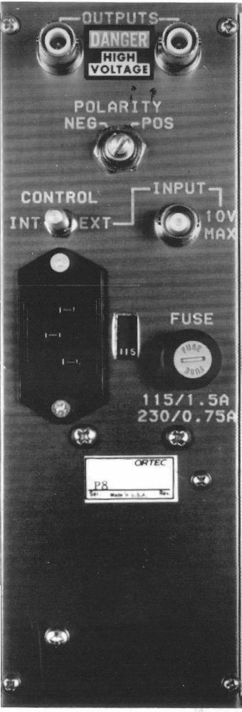
7 1 ORTEC MODEL 556 HIGH VOLTAGE POWER SUPPLY 1. DESCRIPTION The ORTEC Model 556 High Voltage Power Supply is a standard double-width NIM module that provides either polarity of output voltage from 50 V to 3000 V, 0 to 10 ma. The adjusted output voltage of the selected polarity is available simultaneously through two SHV rear-panel connectors. A rearpanel slide switch permits operation on either 115 V or 230 V ac input power, furnished through a removable power line cord and connector. The Model 556 features a front-panel LCD meter which can be programmed via a front-panel toggle switch to display either output voltage or load current. The output voltage can be programmed by an external control via a rear-panel BNC connector. The Model 556 provides the extremely stable, lownoise, high voltage that is required for proper bias of photomultiplier tubes, ionization chambers, and semiconductor detectors. DANGER THIS INSTRUMENT PRODUCES EXTREMELY HAZARDOUS VOLTAGES AT A POTENTIALLY LETHAL CURRENT LEVEL. NEVER CONNECT OR DISCONNECT THE HIGH VOLTAGE OUTPUT CONNECTOR WITH THE POWER SWITCH ON. NEVER CHANGE THE OUTPUT POLARITY SWITCH WITH THE POWER SWITCH ON. ALWAYS SWITCH POWER OFF AND WAIT AT LEAST 30 SECONDS BEFORE CONNECTING OR DISCONNECTING CABLES AND BEFORE CHANGING THE OUTPUT POLARITY. 2. SPECIFICATIONS 2.1. PERFORMANCE OUTPUT POLARITY Positive or negative, selected by switch on rear panel. OUTPUT RANGE 50 to 3000 V; minimum usable voltage 10 V. OUTPUT LOAD CAPACITY 0 to 10 ma. REGULATION <0.0025% variation in output voltage for combined line and load variations within operating range at constant ambient temperature. TEMPERATURE INSTABILITY <±50 ppm/ec after 30 min warmup; operating range 0 to 50EC. LONG-TERM DRIFT <0.01%/hour and <0.03% per 24 hr variation in output voltage at constant input line voltage, load, and ambient temperature after 30 min warmup. OUTPUT RIPPLE 15 mv peak-to-peak, 20 Hz to 20 MHZ. OVERLOAD PROTECTION Internal circuitry protects against overloads including short circuits. RESETTABILITY Output voltage can be reset to within 0.1% CONTROLS POWER Front-panel switch energizes unit when power cord is connected to appropriate source, and an adjacent red LED lamp indicates when power is
8 2 applied. OUTPUT LEVEL One 6-position switch, one 5-position switch, and one 10-turn precision potentiometer; output level is the sum of the 3 settings. METER Front-panel switch selects display of output voltage in kv or load current in ma. POLARITY Rear-panel switch selects either positive or negative output polarity. CONTROL Rear-panel locking switch selects the reference source for the output voltage.! lnt Selects the internal reference source; the front-panel controls select the output amplitude.! Ext Selects the external reference source; output voltage is proportional to magnitude of reference input. AC VOLTAGE Rear-panel slide switch selects either 115 V or 230 V ac input voltage INPUTS AC POWER V or V, Hz, 70 W nominal at full output power; supplied through international standard IEC power connector on rear panel. Fuse rating: 1.5 A (FAST) (250V) size 3AG for 115V or 0.75A(F) (250V) size 5 20 mm for 230V ac operation. EXTERNAL CONTROL Full range of output voltage can be based on an external dc reference level furnished through a rear-panel BNC connector; control voltage range is 0 through ±6.9 V dc; control voltage polarity must be the same polarity as that selected by the rear-panel Polarity switch; this input protected against over-voltages >±7 V. Input impedance >45 kω OUTPUTS REGULATED DC OUTPUT The adjusted and regulated voltage, with selected polarity, is furnished simultaneously to the two SHV connectors on the rear panel INDICATOR METER Front-panel LCD display indicates output voltage in kv ±10 V or load current in ma ±10 µa. Load current is sum of external load current and internal load current. Internal load resistance is -5 MΩ ELECTRICAL AND MECHANICAL POWER REQUIREMENTS Hz, 70 W nominally. WEIGHT! Net 3.6 kg (8 lb)! Shipping 4.5 kg (10 lb) 115 or 230 V ac, DIMENSIONS Standard double-width NIM module, per DOE/ER-0457T ACCESSORIES AVAILABLE Two 3.66 m (12 ft) adapter cables are available from ORTEC for connecting to the Model 556 SHV output connectors: 1. ORTEC C cable assembly: RG-59 A/U (75 Ω) cable with one C-37 SHV female plug and one C-26 MHV male plug. 2. ORTEC C cable assembly: RG-59 A/U (75 Ω) cable with two C-37 SHV female plugs RELATED EQUIPMENT Each of the two outputs of the Model 556 can be used as a power source for any application that is within the operating limits of the power supply. Both output levels are identical and of the same polarity. The load on the Model 556 output circuit is the sum of the individual loads connected to the output connectors, and the load current can be monitored by the front panel LCD meter. This power supply is ideal for use with either one detector or a pair of detectors where the voltage level requirements are the same for both detectors. The appropriate types of detectors for which the Model 556 is designed include photomultiplier tubes, ionization chambers, and semiconductor detectors.
9 3 3. INSTALLATION 3.1. GENERAL The Model 556 is normally used in conjunction with other modular electronics and may be installed in a standard NIM bin such as an ORTEC Model 4001A. Since the bin may be rack mounted, any high temperature equipment that may be installed in the same rack as the bin must be sufficiently cooled by circulating air to prevent exceeding the +50EC (120EF) maximum operating temperature of the 556. The ORTEC M127/N NIM Fan is available for forced-air cooling of a rack of equipment CONNECTION TO POWER The Model 556 requires a grounded ac-power source of nominal 115 V ac or 230 V ac. A rear panel international-standard IEC connector allows the connection of many different types of line cords between the ac outlet and the 556. A rear-panel slide switch allows the choice of 115 V ac or 230 V ac input voltages. The 556 is shipped with a choice of two fuse holder caps to accommodate either 3AG or 5 20 mm size fuses. On 115 V ac operation a 1.5 A (FAST) (250V) size 3AG fuse should be used; on 230 V ac operation, a 0.75A(F) (250V) size 5 20 mm fuse should be used. This power supply may be operated entirely removed from the 4001A bin if desired, since it is totally self-contained and requires no dc-operating power levels from the NIM bin. However, precautions should be taken to ensure that personnel is aware of the shock hazard at the rear connectors, and that air space should be provided at the top and bottom of the instrument CONNECTING INTO A SYSTEM 1. Check to see that the power switch is in the Off position. 2. Check rear panel 115/230 V ac switch and set to appropriate position. 3. Install a 1.5 A, 250 V fuse for 115 V ac setting or a 0.75 A, 250 V fuse for 230 V ac setting in the rear-panel-mounted fuse holder. 4. Check the polarity switch on the rear panel and set it for either positive or negative output polarity as required for the application. 5. Connect a high-voltage cable from either output connector on the 556 to the instrument to be powered. Use the other output connector if a second instrument is to be operated at the same output voltage. 6. Set the front-panel selector switches and potentiometer for the desired voltage level. This is normally specified for the instruments to which the voltage is to be applied. The adjusted output voltage will be the sum of the settings of all three controls. 7. Turn on the power with the switch on the front panel. The indicator lamp next to the switch will light to show that input power is being applied. The indicating meter at the top of the front panel will also indicate the polarity and amplitude of either the 556 output voltage or load current, depending on the setting of the meter switch CONNECTING AN EXTERNAL REFERENCE INPUT The Model 556 output voltage level can be controlled by an external reference level that is furnished through the rear-panel BNC connector when the Control locking switch is set at Ext. The range of input voltage is 0 to 6.9 V to provide an output from 0 to 3000 V. The front- panel voltage level controls are ineffective for external reference operation. For positive output the polarity selector switch on the rear panel is set at Pos, and the external reference should be positive. For negative output the polarity switch is set at Neg and the external reference should be negative. The external reference voltage should be stable and filtered since the output is linearly proportional to this reference. The external reference should be capable of driving the 45 kω input impedance.
10 4 4. CIRCUIT DESCRIPTION Figure 2 is a simplified block diagram of the Model 556 circuits. The 556 requires an ac power input, regardless of the use of an internal or external reference level. The selected reference level is applied to a precision regulator and controls the low voltage input level to an internal 24-kHz oscillator. The oscillator output voltage is stepped up for the high voltage output through a converter transformer, and this signal is rectified and filtered to produce the output to each output connector. The front panel meter (M1) is connected to the output connectors through R65, R85, and R66 when monitoring output voltage. R66 is used to calibrate the front-panel display meter. In the load current display mode, the output ground return current is sensed by R69. The sensed voltage is inverted by S7 and fed to meter M1. Two feedback loops, one for preregulation and one for output regulation, operate simultaneously. To maintain the output voltage at a constant voltage, U1 compares the sampled output voltage against the reference voltage appearing at its input terminals. The resulting error signal is amplified by U2, Q1, and Q5. The output (emitter) of Q5 feeds the input of the high frequency dc-to-dc converter. The converter is made up of a free-running oscillator (Q6-9) driving chopper MOSFETs Q10 and Q11, which alternately switch on to transfer energy through high-voltage transformer T2. The converter output consists of the rectified, filtered, and doubled high voltage at C17. R53 and C18 further filter the output voltage. A preregulator circuit is necessary to limit the power dissipation by Q5. Therefore its collector and emitter voltages are compared at U3(5 and 6). The resulting output represents a request for more Q5 collector voltage. U3(1) is synchronized with the power line frequency. This signal clocks JK flip-flop U4 and when U3(7) is high, SCR Q12 is fired in synchronization with the power line through Q2, Q3, and D8. When SCR Q12 fires, current flows through R3 and C1, boosting the collector voltage at Q5. Current limiting transistor Q4 monitors the current through R4 and prevents damage during output overload by conducting current away from the base of Q5. Also, if a high voltage output should become shorted to ground, transistors Q14 and Q15 will conduct current away from the base of Q5. Current Fig. 2. Model 556 Block Diagram.
11 5 pulses in the ground return path during a short circuit condition produce voltage pulses across R69 which are of sufficient amplitude to turn either Q14 or Q15 On, depending upon the setting of the POLARITY switch (R.P.). Q15 will become active if the switch is set for POS and Q14 will be active if the switch is in the NEG position. Regulators U5 and U6 provide the necessary internal ±12 V power to operate the control circuitry, the reference circuit, and the oscillator. 5. MAINTENANCE AND TROUBLESHOOTING 5.1. GENERAL The Model 556 should not require maintenance other than cleaning to prevent leakage paths from being created by dust collection. If an apparent malfunction is noted, it is important to determine if it is within the 556 power supply by disconnecting it from its load and performing routine diagnostic tests. The 556 is short-circuit protected, and with a shortcircuit load the output voltage will drop to zero. If an external short circuit has been applied to the output, the short circuit must be removed before the 556 will again produce its adjusted voltage TROUBLESHOOTING SUGGESTIONS Only service technicians trained and experienced in the service of high-voltage circuitry should attempt trouble-shooting this unit. EXTREMELY DANGEROUS VOLTAGE LEVELS ARE PRESENT INSIDE THE 556 CHASSIS! OBSERVE GREAT CAUTION WHEN ANY PROTECTIVE COVERS ARE REMOVED WITH POWER APPLIED! To troubleshoot the 556, check the internal ±12 V supplies first, then check for symmetrical conduction times for oscillator output MOSFETs Q10 and Q11. With the 556 set for, positive polarity, the voltages at U1 (2 and 3) should be nearly identical and equal to the reference voltage setting. If this is not the case, check components through the two regulating feedback loops described in Section 4.
12 6 [Intentionally blank]
ORTEC. Model 4006 Minibin and Power Supply Operating Manual. Printed in U.S.A. ORTEC Part No Manual Revision B
 ORTEC Model 4006 Minibin and Power Supply Operating Manual Printed in U.S.A. ORTEC Part No. 774830 1202 Manual Revision B Advanced Measurement Technology, Inc. a/k/a/ ORTEC, a subsidiary of AMETEK, Inc.
OPERATING INSTRUCTIONS
 CM OPERATING INSTRUCTIONS 9 Function, Auto Range Digital Multi-Meter DM6450 INTERTEK Read this owner s manual thoroughly before use and save. C LISTED US I. DISPLAY FUNCTIONS & SYMBOLS 9 6 10 11 14 8 7
Instruction Manual AVTM for. Strip Chart Recorder Catalog Nos and
 AVTM220003 Rev. B January 2003 Instruction Manual AVTM220003 for DC µa Strip Chart Recorder Catalog Nos. 220003 and 220003-47 PO Box 9007 Valley Forge, PA 19485-1007 U.S.A. 610-676-8500 Shipping Address:
Matrix APAX. 380V-415V 50Hz TECHNICAL REFERENCE MANUAL
 Matrix APAX 380V-415V 50Hz TECHNICAL REFERENCE MANUAL WARNING High Voltage! Only a qualified electrician can carry out the electrical installation of this filter. Quick Reference ❶ Performance Data Pages
BroadBand PowerShield. 20 AHr Battery. User Manual
 BroadBand PowerShield 20 AHr Battery User Manual 990-1316A 10/2004 Chapter 1 General Information The PowerShield provides a power source for broadband telephony applications. Important Safety Instructions
VP-4124/VP-4124-E 24/48 VOLT DC SWITCHING POWER SUPPLY
 Issue 5 24/48 VOLT DC SWITCHING POWER SUPPLY INTRODUCTION These instructions provide the specifications, installation and maintenance information for the VP-4124 and VP-4124-E, 24/48 Volt Power Supplies.
& HIGH CURRENT DC POWER SUPPLIES INSTRUCTION MANUAL
 72-6850 & 72-6852 HIGH CURRENT DC POWER SUPPLIES INSTRUCTION MANUAL Table of Contents Introduction 2 Specification 2 Safety 4 EMC 5 Installation 6 Connections 6 Operation 7 Maintenance and Repair 8 www.tenma.com
MY /2-DIGIT DIGITAL MULTIMETER Users Manual
 MY-65 4 1/2-DIGIT DIGITAL MULTIMETER Users Manual Read the Users Manual thoroughly before use. WARRANTY This instrument is warranted to be free from defects in material and workmanship for a period of
INSTRUCTION MANUAL M110A Fax: (503)
") INSTRUCTION MANUAL M110A 1-800-547-5740 Fax: (503) 643-6322 www.ueitest.com email: info@ueitest.com Introduction The M110A, in addition to high-resolution voltage and ohms scales needed for electrical
INSTRUCTION MANUAL M110A 1-800-547-5740 Fax: (503) 643-6322 www.ueitest.com email: info@ueitest.com Introduction The M110A, in addition to high-resolution voltage and ohms scales needed for electrical
OPERATING INSTRUCTION
 11/05 Form #273 OPERATING INSTRUCTION MODEL 4105 Disital Earth Resistance Tester 2150 joshua's Path, Suite 302, Hauppauge, NY 11788 Phone : 1-800-645-5398 or 1-639-231-7050 Fax : 1-639-434-3128 E-mail
Model 616 Rotating Disk Electrode Instruction Manual
 Model 616 Rotating Disk Electrode Instruction Manual 219303 C / 1202 Printed in USA Advanced Measurement Technology, Inc. a/k/a Princeton Applied Research, a subsidiary of AMETEK, Inc. WARRANTY Princeton
SCR Power Controllers
 SCR Power Controllers Instruction Manual SCR POWER CONTROLLERS TABLE OF CONTENTS General Description and Specifications...1 Firing Modes....2 Installation and Wiring...4 Operation...9 Troubleshooting...15
CBC-802 Plug-In Clutch/Brake Control with Solid State Switching
 DIST. AUTORIZADO Plug-In Clutch/Brake Control with Solid State Switching P-29-5 19-0409 Service & Installation Instructions An Altra Industrial Motion Company DIST. AUTORIZADO Brake (Red) and clutch (Green)
24/3000H-3PH 24/4500H-3PH 24/6000H-3PH
 Manufacturer of Dimensions TM Inverters 4467 White Bear Parkway St. Paul, MN 55110 Phone: 651-653-7000 Fax: 651-653-7600 E-mail: inverterinfo@sensata.com Web: www.dimensions.sensata.com 120015D OWNERS
Dimensions 12/800N 12/1200N D. DC to AC Power Inverters. OWNERS MANUAL for Models: OWNERS MANUAL April ISO 9001:2000 Certified Company
 Manufacturer of Dimensions Inverters 4467 White Bear Parkway St. Paul, MN 55110 Phone: 651-653-7000 Fax: 651-653-7600 E-mail: inverterinfo@sensata.com Web: www.dimensions.sensata.com OWNERS MANUAL April
ADI-125/750 ADI-125/1500 ADI-125/2500
 Manufacturer of Dimensions TM Inverters 4467 White Bear Parkway St. Paul, MN 55110 Phone: 651-653-7000 Fax: 651-653-7600 E-mail: inverterinfo@sensata.com Web: www.dimensions.sensata.com 121094B OWNERS
MODEL PS-4 DIGITAL PORTION SCALE
 MODEL PS-4 DIGITAL PORTION SCALE OWNER S MANUAL CARDINAL SCALE MFG. CO. 8528-M317-O1 Rev A 203 E. Daugherty, Webb City, MO 64870 USA 07/05 Ph: 417-673-4631 Fax: 417-673-2153 www.detectoscale.com Technical
DC to AC Power Inverters
 Manufacturer of Dimensions TM Inverters 4467 White Bear Parkway St. Paul, MN 55110 Phone: 651-653-7000 Fax: 651-653-7600 E-mail: inverterinfo@sensata.com Web: www.dimensions.sensata.com ISO 9001:2000 Certified
Model 1672, 1673 Triple Output Power Supply
 Model 1672, 1673 Triple Output Power Supply INSTRUCTION MANUAL 1 Safety Summary The following safety precautions apply to both operating and maintenance personnel and must be observed during all phases
DC to AC Power Inverters
 Manufacturer of Dimensions TM Inverters 4467 White Bear Parkway St. Paul, MN 55110 Phone: 651-653-7000 Fax: 651-653-7600 E-mail: inverterinfo@sensata.com Web: www.dimensions.sensata.com 121114C OWNERS
TL-105-D COLUMN HEATER
 TL-105-D COLUMN HEATER INSTRUCTION MANUAL Timberline Instruments Inc. 1880 S. Flatiron Ct., Unit I Boulder, Colorado 80301 Ph: (303) 440-8779 Fx: (303) 440-8786 info@timberlineinstruments.com www.timberlineinstruments.com
The function of this Dynamic Active Probe has divided into three preferences on the screen main Menus:
 1.0 Introduction: This probe is designed to provide an additional help to automotive technicians in trouble shooting of electrical circuits problems in the car. Apart from using the normal multi tester,
Price Computing Scale D Series Operation Manual
 This Document is Hosted by: www.oldwillknottscales.com Price Computing Scale D Series Operation Manual Cardinal Scale Manufacturing Co. 8529-M400-O1 Rev. A PO BOX 151 WEBB CITY, MO 64870 04/13 PH (417)
OWNERS MANUAL JANUARY 2007 ISO
 Manufacturer of Dimensions TM Inverters 4467 White Bear Parkway St. Paul, MN 55110 Phone: 651-653-7000 Fax: 651-653-7600 E-mail: inverterinfo@sensata.com Web: www.dimensions.sensata.com OWNERS MANUAL JANUARY
WF-5110R True Sine Wave Inverter
 Operator s Manual WF-5110R True Sine Wave Inverter WF-9900 Series WF-5110R ( The Inverter model number is located on the label on top of the enclosure) Distributed in the U.S.A. and Canada by ARTERRA DISTRIBUTION
User s Manual. ClipperCreek, Inc. Innovative Infrastructure for Electric and Hybrid Vehicles. Model PCS-15
 ClipperCreek, Inc. Innovative Infrastructure for Electric and Hybrid Vehicles User s Manual ClipperCreek, Inc. 11850 Kemper Rd., Suite E Auburn, CA 95603 www.clippercreek.net Model PCS-15 THIS PAGE INTENTIONALLY
MIL-24/2600Q MIL-24/3200DQ
 Manufacturer of Dimensions TM Inverters 4467 White Bear Parkway St. Paul, MN 55110 Phone: 651-653-7000 Fax: 651-653-7600 E-mail: inverterinfo@sensata.com Web: www.dimensions.sensata.com 121473B OWNER'S
Patient Lift Scale Indicator Owner s Manual
 Patient Lift Scale Indicator Owner s Manual Item # 13046 INTRODUCTION Thank you for purchasing the Model PL600DM Patient Lift Scale Indicator. It has been manufactured with quality and reliability. This
UL/cUL FILE NUMBER E CE See last page of manual for CE Declaration of Conformity.
 INSTALLATION, OPERATION and MAINTENANCE MANUAL MODEL SCPF1 15, 25, 40 & 65 AMP SCR POWER CONTROLS UL/cUL FILE NUMBER E151547 CE See last page of manual for CE Declaration of Conformity. AMETEK HDR POWER
OPERATING INSTRUCTIONS
 OPERATING INSTRUCTIONS Digital Clamp Meter DSA500A IMPORTANT: RECEIVING INSTRUCTIONS Visually inspect all components for shipping damage. If you find damage, notify the carrier at once. Shipping damage
Reach ins, Freeezers & Refrigerators Installation & Operation Manual
 Reach ins, Freeezers & Refrigerators Installation & Operation Manual BSR23 BSF23 BSR49 BSF49 BSR72 BSF72 IMPORTANT SAFETY INSTRUCTIONS (SAVE THESE INSTRUCTIONS) Visit us on the web at www.blueairinc.com
OWNERS MANUAL JANUARY 2007 ISO
 Manufacturer of Dimensions TM Inverters 4467 White Bear Parkway St. Paul, MN 55110 Phone: 651-653-7000 Fax: 651-653-7600 E-mail: inverterinfo@sensata.com Web: www.dimensions.sensata.com 121231B OWNERS
MARINER MODEL WPS12 WATERPROOF DIGITAL PORTION SCALE OWNER S MANUAL
 MARINER MODEL WPS12 WATERPROOF DIGITAL PORTION SCALE OWNER S MANUAL CARDINAL SCALE MFG. CO. 8528-0409-0M Rev A PO BOX 151 WEBB CITY, MO 64870 04/15 PH (417) 673-4631 FAX (417) 673-5001 www.detectoscale.com
Triple Output Power Supply
 Test Equipment Depot - 800.517.8431-99 Washington Street Melrose, MA 02176 TestEquipmentDepot.com Model 1672, 1673 Triple Output Power Supply INSTRUCTION MANUAL 1 Safety Summary The following safety precautions
CBC-802 Plug-In Clutch/Brake Control with Solid State Switching
 CBC-02 Plug-In Clutch/Brake Control with Solid State Switching P-2104-WE 19-054 Service & Installation Instructions An Altra Industrial Motion Company Brake (Red) and clutch (Green) indicator lights When
PHOTOMULTIPLIER POWER SUPPLY MODEL 70706
 150 Long Beach Boulevard Stratford, CT 06615 Phone: (203) 377-8282 (800) 714-5393 Fax: (203) 378-2457 E-MAIL: oriel.sales@newport.com MODEL 70706 USER MANUAL Please read these instructions completely before
Operator Manual For use with WFCO ULTRA III Deckmount Converter WF-9800 Series (model number located on the cover of the unit)
") Operator Manual For use with WFCO ULTRA III Deckmount Converter WF-9800 Series (model number located on the cover of the unit) Distributed in the U.S.A. and Canada by ARTERRA DISTRIBUTION Warranty Service
Operator Manual For use with WFCO ULTRA III Deckmount Converter WF-9800 Series (model number located on the cover of the unit) Distributed in the U.S.A. and Canada by ARTERRA DISTRIBUTION Warranty Service
MAINFRAME HOT RUNNER TEMPERATURE CONTROL SYSTEMS. Instruction Manual
 MAINFRAME HOT RUNNER TEMPERATURE CONTROL SYSTEMS Instruction Manual Copyright, Athena Controls, Inc., 2006 Printed in USA CompuStep is a registered trademark of Athena Controls, Inc. SafeChange is a trademark
SPC Series. Digital Scale. Operation Manual
 SPC Series Digital Scale Operation Manual Revision 1.0 August 17, 2000 ! WARNING Use only the AC adapter which comes with the scale. Other adapters may cause damage. Internal service to this product should
TS69 TS65 TS55 TS45 TS5768 TS SERIES INSTALLATION/OWNER'S MANUAL
 TS69 TS65 TS55 TS45 TS5768 TS SERIES INSTALLATION/OWNER'S MANUAL Car Audio Speakers TS SERIES PREPARATION Getting Started Thank you for purchasing the TS Series car speakers. Although Dual has attempted
99 Washington Street Melrose, MA Fax TestEquipmentDepot.com. Instruction Manual. Model 1672 Triple Output Power Supply
 99 Washington Street Melrose, MA 02176 Fax 781-665-0780 TestEquipmentDepot.com Instruction Manual Model 1672 Triple Output Power Supply Contents Section Description Page No. CONTENTS 1 1 TEST INSTRUMENT
DUAL 60V 20A POWER FLEX POWER SUPPLY INSTRUCTION MANUAL
 72-7570 DUAL 60V 20A POWER FLEX POWER SUPPLY INSTRUCTION MANUAL Table of Contents Specification 1 Safety 3 EMC 4 Installation 5 Connections 5 Operation 6 Maintenance 8 Specification General specifications
TC26-B Vehicle Sensor
 Section 1 General Description The Model TC26-B is a microprocessor controlled vehicle sensor with a variable range. It is designed to trigger the operation of a traffic controller. The TC26-B will only
Airpax Dimensions, Inc.
 Airpax Dimensions, Inc. 4467 White Bear Parkway (651) 653-7000 St. Paul, MN 55110-7626 Fax (651) 653-7600 121177B OWNERS MANUAL JANUARY 2007 Airpax Dimensions, Inc. Uninterruptible Power System OWNERS
VP-6124/VP-6124-E 24 VOLT DC SWITCHING POWER SUPPLY
 Issue 6 VP-6124/VP-6124-E 24 VOLT DC SWITCHING POWER SUPPLY INTRODUCTION These instructions provide the specifications, installation and maintenance information for the VP-6124 and VP-6124-E, 24Volt Power
This document describes:
 Thank you for purchasing this product from ERM. We appreciate your interest in our unique product line as we try to offer our customers an alternative to today s traditional products. This programmable
1 AMP CURRENT SOURCE
 1 AMP CURRENT SOURCE CS-2000-U CS-2000-E USER MANUAL BC BIOMEDICAL CS-2000 SERIES TABLE OF CONTENTS WARNINGS, CAUTIONS, NOTICES... ii DESCRIPTION... 1 LAYOUT... 2 OPERATION... 4 TESTING... 6 MANUAL REVISIONS...
Triple Output High Resolution Power Supply. User Manual
 1320 Triple Output High Resolution Power Supply User Manual Safety Summary The following safety precautions apply to both operating and maintenance personnel and must be observed during all phases of operation,
INSTRUCTION MANUAL DM5B Fax: (503)
") INSTRUCTION MANUAL DM5B 1-800-547-5740 Fax: (503) 643-6322 www.ueitest.com email: info@ueitest.com Introduction The DM5B digital multimeter is a pocket sized, hand held, battery operated, voltage, current
INSTRUCTION MANUAL DM5B 1-800-547-5740 Fax: (503) 643-6322 www.ueitest.com email: info@ueitest.com Introduction The DM5B digital multimeter is a pocket sized, hand held, battery operated, voltage, current
Filtered PWM Speed Control for Permanent Magnet DC Motors
 Instructions for Installation and Operation Filtered PWM Speed Control for Permanent Magnet DC Motors Model 0794 Speed and Direction Control up to 5/8 HP NEMA-1/IP-20 Specifications Product Type:... WPM-2148E1
Video & Power Over Coax Kit
 VPoC User Manual Video & Power Over Coax Kit 1CH Video Power over Coax w/ 12V DC Receiver Device VPoC24DC-01K VPoC24DC-01 N-42-1 x1 N-41C 4CH / 8CH / 16CH Video Power over Coax Server Kit VPoC24DC-04K
BENCHTOP INSTRUMENT. Multi-channel DC Power Supply TP2000N/TP2000PU/TP4000N Series Operation Manual V1.0
 BENCHTOP INSTRUMENT Multi-channel DC Power Supply TP2000N/TP2000PU/TP4000N Series Operation Manual V1.0 CONTENTS 1. INTRODUCTION... - 1-2. PRODUCTION MODELS... - 2-3. SPECIFICATIONS... - 3-4. PANEL CONTROLS
FLEETWOOD TRAVEL TRAILER SLIDEOUT SYSTEM OWNER S MANUAL
 FLEETWOOD TRAVEL TRAILER SLIDEOUT SYSTEM OWNER S MANUAL 82-S0150-01 REV. 1 April, 2002 TABLE OF CONTENTS PAGE # OPERATIONS MANUAL... 1 1. SYSTEM DESCRIPTION... 1 1.1 MAJOR COMPONENTS... 1 2. HOW TO OPERATE
REFERENCE MANUAL FORM: MX-TRM-E REL REV MTE
 Matrix APAX 380V-415V 50Hz TECHNICAL REFERENCE MANUAL FORM: MX-TRM-E REL. September 2014 REV. 002 2014 MTE Corporation WARNING High Voltage! Only a qualified electrician can carry out the electrical installation
CBC-300 Series & CBC-300C Series Dual Channel Adjust Clutch/Brake Controls
 CBC-300 Series & CBC-300C Series Dual Channel Adjust Clutch/Brake Controls P-269-89-0408 Installation Installation & Operating Instructions Contents Introduction........................... 2 Specifications.........................
BAK1500 INSTALLATION/OWNER'S MANUAL Compact Amplified Subwoofer
 BAK1500 INSTALLATION/OWNER'S MANUAL Compact Amplified Subwoofer PREPARATION Getting Started Thank you for purchasing the Dual BAK1500 compact amplified subwoofer. Although Dual has attempted to ensure
Model 700 Microarray Oven
 www.scigene.com Model 700 Microarray Oven USER MANUAL Cat. #1070-00-1, 1070-00-2 FOR RESEARCH USE ONLY Not for Use in Diagnostic Procedures SciGene 306 Potrero Ave, Sunnyvale, CA 94085 USA 408-733-7337
INSPECTOR LINE LOAD SIMULATOR INSTRUCTION MANUAL TASCO, INC.
 INSPECTOR LINE LOAD SIMULATOR INSTRUCTION MANUAL INS120P TASCO, INC. THIS TESTER IS DESIGNED FOR USE ONLY BY QUALIFIED ELECTRICIANS. IMPORTANT SAFETY WARNINGS mwarning Read and understand this material
Broadband PowerShield. CP27U Models. User Manual
 Broadband PowerShield CP27U Models User Manual 990-2366C 04/2016 Chapter 1: General Information The PowerShield provides a power source for broadband telephony, Fiber-to-the-Home/Premise (FTTH/P), and
POWER SUPPLY MODEL XP-800. TWO AC VARIABLE VOLTAGES; 0-120V and 7A, PLUS UP TO 10A. Instruction Manual. Elenco Electronics, Inc.
 POWER SUPPLY MODEL XP-800 TWO AC VARIABLE VOLTAGES; 0-120V and 0-40V @ 7A, PLUS 0-28VDC @ UP TO 10A Instruction Manual Elenco Electronics, Inc. Copyright 1991 Elenco Electronics, Inc. Revised 2002 REV-I
1000-Watt Energy Center
 1000-Watt Energy Center OPERATING INSTRUCTIONS Patent Pending Sierra Wave 1000-Watt Energy Center #9675 The Sierra Wave 1000-Watt Energy Center is a heavy duty and efficient portable power center offering
AUTO-BLiP. User Manual Lotus INTELLIGENT DOWNSHIFTS. Version 1.0
 AUTO-BLiP INTELLIGENT DOWNSHIFTS www.auto-blip.com User Manual Lotus Version 1.0 Copyright 2012 Tractive Technology, LLC. All rights reserved. Page 1 WARNING Use of the AUTO-BLiP while driving could lead
PHASERS. Operating and Instruction Manual. a n d A C C E S S O R I E S
 VOLTMETERS PHASERS a n d A C C E S S O R I E S Operating and Instruction Manual HD ELECTRIC COMPANY 1 4 7 5 L A K E S I D E D R I V E WA U K E G A N, I L L I N O I S 6 0 0 8 5 U. S. A. PHONE 847.473.4980
Easy Packer. Industrial Case Erecting, Packing and Taping System. User Guide
 Easy Packer Industrial Case Erecting, Packing and Taping System User Guide Easy Packer Industrial Case Erecting, Packing and Taping System User Guide Revised 04/19/2012 P/N XXXXXXX Rev A Copyright and
TBX10A INSTALLATION/OWNER'S MANUAL 10" Sealed Enclosure with Built-in Amplifier
 TBX10A INSTALLATION/OWNER'S MANUAL 10" Sealed Enclosure with Built-in Amplifier Getting Started Thank you for purchasing the Dual TBX10A 10" ported enclosure with built-in amplifier. Although Dual has
PL900 ILLUMINATOR. Fiber-Lite. Operation Manual. Setup. Fiber Optic Connection A PRODUCT OF DOLAN-JENNER INDUSTRIES. Voltage Selection:
 PL900 ILLUMINATOR A PRODUCT OF DOLAN-JENNER INDUSTRIES Setup Voltage Selection: Operation Manual Read and review the instructions on the label covering the power entry module and the instructions in this
Model HPX60 Series Automatic Battery Charger User s Manual Rev. 1.0 October 17, 2006
 B R A N D Model HPX60 Series Automatic Battery Charger User s Manual Rev. 1.0 October 17, 2006 For Sales, Support and Service phone: 407-331-4793 fax: 407-331-4708 website: www.xenotronix.com email: information@xenotronix.com
Installation Power Management Unit Battery Cables and Battery Harness
 Installation Power Management Unit Battery Cables and Battery Harness Important Safety Messages SAVE THESE INSTRUCTIONS - This manual contains important instructions that should be followed during installation
BP1204 INSTALLATION/OWNER'S MANUAL
 BP1204 INSTALLATION/OWNER'S MANUAL BP1204 PREPARATION Getting Started Thank you for purchasing the Dual Electronics BP1204 Bandpass Subwoofer System. Although Dual has attempted to ensure the information
CBC-160-1N and CBC-160-2N Clutch/Brake Controls
 P-239-36 819-04 CBC-160-1N and Clutch/Brake Controls Installation Instructions An Altra Industrial Motion Company Contents Introduction...2 Specifications........................... 2 Installation...3
miconverter 18-Module Rack-Mount Power Chassis User Manual 38 Tesla, Irvine, CA USA Phone: (949) ; Fax: (949) Page 12
 ; Fax: (949) Page 12") miconverter 18-Module Rack-Mount Power Chassis User Manual Page 12 38 Tesla, Irvine, CA 92618 USA Phone: (949) 250-6510; Fax: (949) 250-6514 General and Copyright Notice This publication is protected by
miconverter 18-Module Rack-Mount Power Chassis User Manual Page 12 38 Tesla, Irvine, CA 92618 USA Phone: (949) 250-6510; Fax: (949) 250-6514 General and Copyright Notice This publication is protected by
INSTALLATION/OWNERS MANUAL
 INSTALLATION/OWNERS MANUAL XOBP12D PREPARATION Getting Started Thank you for purchasing the Dual Electronics XOBP12D Bandpass Subwoofer System. Although Dual has attempted to make sure all of the information
IOA Expansion Cabinet. Dual Line Cords Upgrade Instructions
 IOA Expansion Cabinet Dual Line Cords Upgrade Instructions Notice The information contained in this document is subject to change without notice. STRATUS COMPUTER INC. MAKES NO WARRANTY OF ANY KIND WITH
Blue Air. Commercial Refrigeration Inc. Installation & Operation Manual Glass Door Countertop Refrigerator
 Blue Air Commercial Refrigeration Inc. Installation & Operation Manual Glass Door Countertop Refrigerator Please read this manual completely before installing or operating this unit! BAGR7 Blue Air reserves
Installation Guide. Marine Filter SURT023M SURT024M
 Installation Guide Marine SURT023M SURT024M suo0738a Product Description The APC by Schneider Electric Marine Application reduces the EMI (electro magnetic interference), produced by a connected that
Welcome to PTI--Photon Technology International--Optical Building Blocks!
 Search: GO Power Supplies Model LPS-220 Lamp Power Supply OPERATION MANUAL CONTENTS 1. DESCRIPTION Introduction Specifications 2. INSTALLATION Arc Lamps Tungsten-Halogen Lamps 3. OPERATION Arc Lamps Tungsten-Halogen
DC POWER SUPPLY ALIMENTATION C.C.
 DC POWER SUPPLY ALIMENTATION C.C. ISO-TECH IPS 303A 201-3424 ISO-TECH IPS 601A 201-3446 SAFETY TERMS AND SYMBOLS These terms may appear in this manual or on the product: WARNING. Warning statements identify
INSTALLATION GUIDE. Universal System for Zero Turn Mowers
 INSTALLATION GUIDE Universal System for Zero Turn Mowers Table of Contents General Information 1 Important Notice to Purchaser 2 Specifications 2 Intended Usage 2 Important Information 3 General Safety
EPS/ELA-Series User Manual EPS/ELA 250W
 EPS/ELA-Series User Manual EPS/ELA 250W EPS Stromversorgung GmbH Tel: +49 (0)821 570451 0 Index 3 Page: 1 Table of contents: Page 1. Features of ELA-Series... 3 1.1 Basic Functions... 3 1.2 Options...
INSTALLATION/OWNER'S MANUAL DP " Woofer in Enclosure
 INSTALLATION/OWNER'S MANUAL DP1000 10" Woofer in Enclosure Installation Thank you for purchasing the DP1000 10" Woofer with enclosure. Although Dual has attempted to make sure all of the information contained
LIGHTSTICK / LIGHTSTICK PLUS Germicidal Ultraviolet Light
 LIGHTSTICK / LIGHTSTICK PLUS Germicidal Ultraviolet Light Installation & Operation Manual This manual covers the following models: LightStick #19300 LightStick Plus #19301 GENERAL This product emits germicidal
Web Volume Control Model WV220
 WEB CONTROL PRODUCTS User Manual Web Volume Control Model WV220 1 In accordance with Nexen s established policy of constant product improvement, the specifications contained in this manual are subject
GF1900 SULFURYL FLUORIDE MONITOR
 GF1900 SULFURYL FLUORIDE MONITOR Revision: H Release Date: 12/12/2018 Page 1 of 20 This page intentionally left blank Revision: H Release Date: 12/12/2018 Page 2 of 20 TABLE OF CONTENTS INTRODUCTION......
PowerOhm Installation Manual for BM R Series Braking Modules
 PowerOhm Installation Manual for BM R Series Braking Modules IMPORTANT: These instructions should be read thoroughly before installation. All warnings and precautions should be observed for both personal
Blue Air. Commercial Refrigeration Inc. Installation & Operation Manual Chef Bases
 Blue Air Commercial Refrigeration Inc. Installation & Operation Manual Chef Bases Please read this manual completely before installing or operating this unit! BACB53 BACB71 BACB74 BACB83 BACB86 BACB96
INSTRUCTIONS FOR OUTDOOR WALL LANTERN, MODEL LPT-1107
 INSTRUCTIONS FOR OUTDOOR WALL LANTERN, MODEL LPT-1107 Page 1 Thank you for purchasing this Langport Lighting outdoor wall lantern. This product has been manufactured with the highest standards of safety
GC-1. Roof and Gutter De-Icing Control Installation and Operating Instructions FOR EXTERIOR INSTALLATION ONLY
 GC-1 Roof and Gutter De-Icing Control Installation and Operating Instructions FOR EXTERIOR INSTALLATION ONLY GENERAL INFORMATION The GC-1 heating cable controller has been designed and manufactured for
Contents. Introduction Inspection Notes on Safety Precautions. Chapter 1 Overview Product Overview Names of Parts 2
 INSTRUCTION MANUAL Contents Introduction Inspection Notes on Safety Precautions i i ii vii Chapter 1 Overview 1 1.1 Product Overview 1 1.2 Names of Parts 2 Chapter 2 Specifications 5 2.1 Product Specifications
Adjustable Angled Incline Conveyor Owners Manual with Operating Instructions
 Adjustable Angled Incline Conveyor Owners Manual with Operating Instructions Revision 012211 Table of Contents Basic Conveyor Features 3 Getting Started 4 Setting Up the Incline Conveyor 5 Belt Removal
Power Inverter 400 MW Owner s Manual
 Power Inverter 400 MW 1204 Owner s Manual For safe and optimum performance, the Power Inverter must be used properly. Carefully read and follow all instructions and guidelines in this manual and give special
Model C230 Pump Controller
 MANUAL Model C230 Earthsafe Systems, Inc. 7553 S. Madison Willowbrook, IL 60527 T: (630) 794-5100 F: (630) 794-5106 info@earthsafe.com www.earthsafe.com March 1, 2010 The information contained herein is
Model NTX7 Series Automatic Battery Charger User s Manual Rev. 1.0 October 17, 2006
 B R A N D Model NTX7 Series Automatic Battery Charger User s Manual Rev. 1.0 October 17, 2006 For Sales, Support and Service phone: 407-331-4793 fax: 407-331-4708 website: www.xenotronix.com email: information@xenotronix.com
WF-5110R True Sine Wave Inverter
 Operator s Manual WF-5110R True Sine Wave Inverter WF-9900 Series WF-5110R ( The Inverter model number is located on the label on top of the enclosure) Distributed in the U.S.A. and Canada by ARTERRA DISTRIBUTION
Analog Condensate Monitor Instruction & Maintenance Manual
 Analog Condensate Monitor Instruction & Maintenance Manual Advantage Controls, Inc. PO Box 1472 Muskogee, OK 64402 Phone: 800-743-7431 Fax: 888-686-6212 www.advantagecontrols.com EE-13 email: aci@advantagecontrols.com
Active Controlled Cooling System
 Active Controlled Cooling System April 2011 3267 Progress Dr Orlando, FL 32826 www.apecor.com Preliminary www.apecor.com Table of Contents General Information... 3 Safety... 3 Introduction... 3 What s
WF-5100 Series True Sine Wave Inverters
 Operator s Manual WF-5100 Series True Sine Wave Inverters WF-9900 Series WF-5118 WF-5120 ( The Inverter model number is located on the label on top of the enclosure) Distributed in the U.S.A. and Canada
model ps600 Address all communications and shipments to: FEDERAL SIGNAL CORPORATION
 MODEL: PS600 HZ: 60 A model ps600 installation and service manual for federal model ps600 FEDERAL SIGNAL CORPORATION POWER SUPPLY VOLTS: SERIES: 120VAC FEDERAL SIGNAL CORPORATION UNIVERSITY PARK, IL. U.S.A.
CBC-300 & CBC Series Dual Channel Adjust Clutch/Brake Controls
 CBC-300 & CBC-300- Series Dual Channel Adjust Clutch/Brake Controls P-205-WE 89-0549 Installation & Operating Instructions An Altra Industrial Motion Company Contents Introduction... 2 Specifications...
Table of Contents Title Page No.
 Table of Contents Title Page No. INTRODUCTION 1 SAFETY PRECAUTIONS / WARNINGS 2 CONTROLS AND INDICATORS 4 PREPARATION AND CAUTION BEFORE USE 5 TESTING PROCEDURES 6 A. AC/DC VOLTAGE MEASUREMENT 6 B. RESISTANCE
COLT CELL BATTERY CHARGER Installation and Operating Instructions
 COLT CELL BATTERY CHARGER Installation and Operating Instructions INSTALLATION All COLT chargers are for indoor use only. All COLT chargers are designed for installation into the battery tray. Charging