LA-2400 Series. Established Leaders in Actuation Technology. Installation Manual. Linear Actuators
|
|
|
- Brooke Pierce
- 5 years ago
- Views:
Transcription


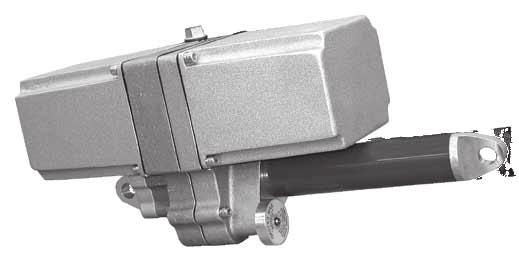

1 LA-2400 Series Installation Manual Linear Actuators Established Leaders in Actuation Technology
2

3 Instruction Manual IM-0443 LA-2400 Series Linear Actuator Table of Contents General Information Introduction... 2 Receiving/Inspection... 2 Storage... 2 Equipment Return... 2 Identification Label... 3 Abbreviations Used in This Manual... 3 General Actuator Description... 3 Basic Models... 3 Product Specifications... 4 Installation... 5 Typical Wiring Diagrams Start-up/Calibration Start-up/Calibration for Units with Amplifier Amplifier Specifications Amplifier Start-up Amplifier Parts Identification Amplifier DIP Switch Chart Typical Amplifier Wiring Diagram Amplifier Troubleshooting Chart Troubleshooting Guide Component Location Drawing Maintenance, Gear and Drive Nut Selection Parts List and Recommended Spares Major Dimensions Due to wide variations in the terminal numbering of actuator products, actual wiring of this device should follow the print supplied with the unit.
4 GENERAL INFORMATION INTRODUCTION Rotork Process Controls, designs, manufactures, and tests its products to meet many national and international standards. For these products to operate within their normal specifications, they must be properly installed and maintained. The following instructions must be followed and integrated with your safety program when installing, using and maintaining Rotork Process Controls products: Read and save all instructions prior to installing, operating and servicing this product. If you do not understand any of the instructions, contact your Rotork Process Controls representative for clarification. Follow all warnings, cautions and instructions marked on, and supplied with, the product. Inform and educate personnel in the proper installation, operation and maintenance of the product. Install equipment as specified in Rotork Process Controls installation instructions and per applicable local and national codes. Connect all products to the proper electrical sources. To ensure proper performance, use qualified personnel to install, operate, update, tune and maintain the product. When replacement parts are required, ensure that the qualified service technician uses replacement parts specified by Rotork Process Controls. Substitutions may result in fire, electrical shock, other hazards, or improper equipment operation. Keep all product protective covers in place (except when installing, or when maintenance is being performed by qualified personnel), to prevent electrical shock, personal injury or damage to the actuator. WARNING Before installing the actuator, make sure that it is suitable for the intended application. If you are unsure of the suitability of this equipment for your installation, consult Rotork Process Controls prior to proceeding. WARNING - ELECTROSTATIC DISCHARGE This electronic control is static-sensitive. To protect the internal components from damage, never touch the printed circuit cards without using electrostatic discharge (ESD) control procedures. RECEIVING/INSPECTION Carefully inspect for shipping damage. Damage to the shipping carton is usually a good indication that it has received rough handling. Report all damage immediately to the freight carrier and Rotork Process Controls Unpack the product and information packet taking care to save the shipping carton and any packing material should return be necessary. Verify that the items on the packing list or bill of lading agree with your own. STORAGE If the product will not be installed immediately, it should be stored in a clean, dry area where the ambient temperature is not less than -20 F. The actuator should be stored in a non-corrosive environment. The actuator is not sealed to NEMA 4 until the conduit entries are properly connected. EQUIPMENT RETURN A Returned Goods authorization (RG) number is required to return any equipment for repair. This must be obtained from Rotork Process Controls. (Telephone: 414/ ) The equipment must be shipped, freight prepaid, to the following address after the RG number is issued: Rotork Process Controls 5607 West Douglas Avenue Milwaukee, Wisconsin Attn: Service Department To facilitate quick return and handling of your equipment, include: RG Number on outside of box Company Name, Contact Person, Phone/Fax No. Address Repair Purchase Order Number Brief description of the problem WARNING - SHOCK HAZARD Installation and servicing must be performed only by qualified personnel. 2
5 GENERAL INFORMATION IDENTIFICATION LABEL LA C / / 1 / 1 95C LA-2410 MODEL NUMBER: LA24 10 Series SERIAL NUMBER: 1627 C 01 Sequential Number Year Built Month Built ABBREVIATIONS USED IN THIS MANUAL A or Amps Ampere AC Alternating Current C Degrees Celsius CW Clockwise CCW Counterclockwise DC Direct Current F Degrees Fahrenheit G Earth Ground Hz Hertz kg Kilogram L Line (power supply) lbs. Pounds lbf. Lbs. Force LVDT Linear Variable Differential Transformer ma Milliamp mfd Microfarad mm Millimeters N Newton (force) NEMA National Electrical Manufacturing Association Nm Newton Meter NPT National Pipe Thread Ph Phase PL Position Limit Switch RPM Revolutions per Minute sec. Second TL Thrust Limit Switch Vac Volts ac Vdc Volts dc VR Variable Resistance W Watt -3- GENERAL ACTUATOR DESCRIPTION The LA-2400 series actuators are electrically operated, bi-directional linear devices. They are designed for strokes to 24 inches (610 mm) and thrusts to 1,500 lbf (6672 N) and include a non-clutchable manual override handwheel. The drive motor may be single or three phase ac, or dc. Options Include: Up to four independently adjustable limit switches Contactless position feedback Linear potentiometer position feedback Thermostatically controlled anti-condensation heater Integral or remote servo-amplifiers Trunnion mounting 4 to 20mA position feedback Shaft bellows Paint/coatings The LA-2400 series include 120/240 Vac single phase models, 240/380/480 Vac three phase models and 24 Vdc models. These actuators are controlled by switched power inputs or by a remotely installed servo-amplifier. The LA-2400 series is also available with an internal servo-amplifier. They require 120 or 240 Vac (depending on model) unswitched, single phase line voltage input and a dc analog command signal for a complete, closed-loop positioning system in a compact enclosure. BASIC MODELS LA-2410, LA-2420, LA-2450 and LA-2490 are all single phase ac, three wire, plug reversible models. They are compatible with Jordan Controls remotely located AD-8240 Series servo amplifiers, or any bi-directional contact type control. These actuators may also be equipped with an internal servo amplifier that features loss of signal detection for current command signal inputs and can be calibrated to allow the actuator to lock-in-place or drive to a preset position should the command signal drop below 3.8mA. Also included is a dynamic brake circuit to increase positioning accuracy. The LA-2415 is a three phase ac, plug reversible model compatible with Jordan Controls remotely located AD servo amplifier or any bi-directional contact type control. The LA-2440 is a dc plug reversible model and is compatible with Jordan Controls remotely located model AD-7530 servo amplifier or other compatible control device.
6 LA-2400 SERIES PRODUCT SPECIFICATIONS GENERAL SPECIFICATIONS ELECTRICAL SPECIFICATIONS Speed / Thrust: Model LA-2410 LA-2415 LA-2450 LA-2420 LA-2490 LA /800 (2.5/3558) 0.1/1500 * (2.5/6672) 0.2/550 (5.1/2446) *1500 lbf. available in 6 in. stroke only. Stroke: 6 to 24 in. (152 to 610 mm) Lubrication & Type: Permanently lubricated, Amoco- Amolith Rykon All-Weather Premium Grease #2. Gearing: Hardened steel spur gear train, self-locking. Temperature: -40 F to 150 F. (-40 C to 65 C) Environment Rating: Dust ignition-proof for Class II, Division I, Groups E, F and G, and Type 4 (IP65) indoor and outdoor. Enclosure Material: Cast Aluminum Alloy. Approximate Weight: 40 lbs. (18kg) Mounting: Clevis mount in any position. Trunnion (not available with 6 in. stroke). When mounted vertically with the ram extending up, option D056 (vertical moisture shield) must be used for wet applications. Manual Handcrank: Permits local operation. Thrust Limiting: Bi-directional (factory set and not adjustable). Modulating Rate: (1% position changes) LA-2415, 1200 starts/hour. All others, 2000 starts/hour. Duty Cycle: Modulating: LA-2410, LA-2415, LA-2440, LA %: LA-2420, LA Clevis: Non-rotating. in. per sec. / lbf. (mm per sec. / N) 0.2/800 (5.1/3558) 0.2/1500 * (5.1/6672) 0.25/550 (6.4/2446) 0.4/200 (10.2/890) 0.4/550 (10.2/2446) 0.6/150 (15.2/667) 0.7/200 (17.8/890) 0.7/450 (17.8/2002) 1/150 (25.4/667) Power Requirements: Model Input Power Current (Amps) Volts/PH/Hz Run Stall LA /1/ LA /480/3/ / /0.65 LA /3/ LA /1/ LA Vdc LA /1/ LA /1/ Voltage Tolerance: +/-10% Conduit Entry: Two, 3/4 NPT. Field Wiring: To barrier terminal blocks. OPTIONS Anti-condensation Heater: 120/240 Vac, 30W Two auxiliary position limit switches: 10A SPDT, 120/240 Vac 1000 ohm Feedback Potentiometer: 2 Watt Max. dc Contactless Feedback: Hall Effect 4-20mA Feedback Transmitter: Isolated, loop-powered Vdc at 25 ma. Maximum Load (ohms) = Power Supply Voltage - 8 High and Low Trim: Adjustable A Servo-Amplifier Model AD-8130: 120/240 Vac. (For more information see Jordan Controls IM-0523). Accuracy: +/-1.0% of full rated travel Repeatibility: 0.5% of full rated travel Hysteresis: 0.5% of full rated travel Linearity: +/-1.0% of full rated travel Input Deadband: Adjustable Loss of Signal: Stays in place or runs to pre-set on current command signals dropping below 3.8 ma (field selectable) Command Signal Inputs: Field selectable 4 to 20 ma (200 ohm impedance) 0 to 5 or 0 to 10 Vdc (100,000 ohm impedance)
7 MOUNTING Refer to installation dimensions on the installation print sent with the actuator. The rear cover (opposite the ram) must have clearance so it can be removed for adjustments and interconnect wiring. The actuator is mounted with pins through the rear and front clevises. The rear clevis is normally the stationary end. The device to be positioned must be such that it will allow retraction and extension. Side loading must be avoided. Side loading will lead to excessive operating thrust which will cause premature bearing failure. The device to be positioned must not require greater thrust than the rating of the actuator. Mount the rear clevis to the stationary actuator support device first, then move the traveling portion of the device to the front clevis and mount it. The front clevis is non-rotating. The installation should place no torque upon the clevis or premature failure of the actuator will result. As an option, trunnion mounting is available on actuators with 12 inch (305 mm) or greater strokes. Dimensional details of this style of mounting is shown on page 18 of this manual. When mounted vertically with the ram extending up, option D056 (vertical moisture shield) must be used for wet applications. INSTALLATION -5- WIRING The wiring diagram on page 6 shows the fundamental connections for standard three-wire reversible singlephase ac motor, standard permanent magnet dc motor, and three phase AC models. The wiring diagram on page 7 shows the fundamental connections for single phase AC actuators with an integral AD-8130 servo-amplifier, along with other options. A barrier type terminal strip is located under the rear enclosure cover at the rear clevis end of the actuator. Two ¾ inch NPT conduit entries are available for field use. See the installation dimension drawing on the last page of this manual for their location. CAUTION: On standard single-phase wiring, the position limit switches and the thrust switches are wired directly in the motor circuit and protect it at the extremes of travel or at thrust cutout. Three phase AC or DC units must have these thrust and position limit switches wired into the controlling device to cause end of travel or thrust shutdown. Care must be taken in wiring these to the controlling device so that the appropriate direction of control is turned off when that direction s limit switch is actuated. If care is not taken in phasing the equipment, damage may occur to the actuator or driven load. All wiring must be done in accordance with prevailing codes by qualified personnel. Typical wiring diagrams are shown on pages 6-7. Actual wiring should follow the wiring diagram supplied with the actuator. Fusing must be installed in line power, and should be of the slow blow type. Wiring must be routed to the actuator through the two conduit openings. Generally, one conduit will contain input power and earth ground wires. The other conduit would then contain low level input and output signal wiring. It is required that all low level signal wiring be a shielded type with the shield grounded at source common. After installation, it is recommended that all conduits be sealed to prevent water damage and to maintain NEMA 4 enclosure rating. Remote mounted servo amplifiers must maintain a maximum of 50 feet of wire run to the actuator.
8 TYPICAL WIRING DIAGRAMS ACTUATOR WITHOUT A BUILT-IN AMPLIFIER LA-2410, LA-2420 (120 Vac) LA-2450, LA-2490 (240 Vac) LA-2440 (24 Vdc) Actuator AC Power Applied to Terminals DC Power Applied to Terminals Action 1 & 2 1 & 3 1(+) & 2(-) 1(-) & 2(+) Viewing Actuator Ram Extend Retract Extend Retract LA-2415 SERIES ACTUATOR Due to wide variations in terminal numbering of actuator products, actual wiring should follow the print supplied with the actuator. Notes: 1. The thrust limit switches (TL1 & TL2) are factory set to trip if the thrust exceeds the actuator rating. 2. Shielded wire is required for command and position feedback signal wiring. -6-
9 TYPICAL WIRING DIAGRAM LA-2400 SERIES ACTUATORS WITH A BUILT-IN AD-8130 AMPLIFIER (120/240 Vac, Single Phase, Hz) Due to wide variations in terminal numbering of actuator products, actual wiring should follow the print supplied with the actuator. Notes: 1. All references to actuator ram movement are as viewed facing the front clevis. 2. An increasing command signal will result in ram extension. 3. The thrust limit switches are factory set to trip if the thrust exceeds the actuator rating. 4. Shielded wire is required for command and position feedback signal wiring. 5. Comand signal input: 4 to 20 ma into a 200 ohm impedance 0 to 5 or 0 to 10 Vdc into a 100,000 ohm impedance 6. Refer to amplifier instruction manual for proper DIP switch settings and amplifier setup. -7-
10 A. LIMIT SWITCH ADJUSTMENT PROCEDURE (see Figure 1) START UP & CALIBRATION The limit switch assembly features up to four independently adjustable position limit switches. The setting of one switch does not affect the setting of the other. Limit switch #1 (PL1) is set to stop the actuator at the actuator fully extended position. Limit switch #2 (PL2) is always set to stop the actuator at the actuator fully retracted position. Each limit switch is activated by an aluminum cam with a detent. When the cam roller falls into this detent, the limit switch goes to its normal state. To readjust the limit switches for the required actuator stroke, the following methods are recommended: 1K ohm potentiometer Fiqure 1 FOR ACTUATOR WITHOUT A POSITION FEEDBACK DEVICE 1. With no power applied to the circuits, manually turn the manual handwheel until there is a slight gap (1/32 ) between the front clevis and the outer support tube with the clevis hole in the required mounting plate. CAUTION: Do not energize the actuator while manual positioning or attempt to engage the manual handwheel while the unit is running. Rotation of the manual handwheel by the motor could inflict personal injury. 2. Loosen both set screws in PL2 cam (set screws are 120 apart). Rotate PL2 cam until the indent of the cam and the roller begin to mate and the limit switch activates (when you hear a click ). Tighten the set screws. 3. Energize the motor and run front clevis to the fully extended position. Loosen both the set screws of PL1 cam and manually rotate the cam until the indent of the cam and the roller begin to mate and the limit switch activates (when you hear a click ). Tighten the set screws. Note: 1K ohm potentiometer and #3 and #4 limit switches are options. 4. The end of travel position limits PL1 and PL2 are now set for full stroke of the actuator. 5. Apply electrical power and run the actuator through its range to check for proper limit switch adjustment. FOR ACTUATOR WITH A POSITION FEEDBACK DEVICE 1. With no power applied to the circuits, connect an ohm meter across the potentiometer wiper arm and the zero (retract) end of the pot. 2. Follow steps 1 through 5 in the previous section. -8-
11 START UP & CALIBRATION A. POSITION FEEDBACK ALIGNMENT (Potentiometer) Position feedback is provided through the use of a potentiometer attached to the limit switch assembly. As the switches are driven by the actuator gearing, the potentiometer is simutaneously driven to provide position feedback. 1. Establish if full extend or full retract is to be used for zero indication. On slide gate installations, zero indication is normally used when the actuator is fully extended and the gate closed. 2. Make sure end of travel limit switches are correctly set for proper stroke length. 3. Use an ohmmeter to monitor the position of the feedback potentiometer wiper to determine which end of the pot gives a low ohm resistance indication. 4. If the reading is greater than 50 ohms, see Position Limit Switch Adjustment Procedure for actuators with a potentiometer. 5. Run the actuator through its stroke range to ensure the potentiometer is tracking through its electrical range. (Generally 60 to 90% of 1,000 ohms). NOTE: On tandem potentiometer assembly, set the bottom potentiometer to approximately 50 ohms. B. POSITION FEEDBACK ALIGNMENT (Contactless) Position feedback can also be provided through the use of a contactless feedback device attached to the limit switch assembly. As the switches are driven by the actuator gearing, the feedback device is simutaneously driven to provide position feedback. C. 4 to 20mA TRANSMITTER ADJUSTMENT The ST-4130 (1000 ohm-input, 4 to 20mA output) two wire transmitter modulates the current on a direct current supply proportional to the input resistance. It is powered by a 12.0 to 36.0 Vdc unregulated power supply line which is modulated from 4 to 20mA proportional to the resistance of the input. 800 ohm maximum load when power supply is 24 Vdc For the unit to function properly the 4mA end of the feedback potentiometer must be preset to 50 ohms. 1. Position the actuator to the desired 4mA setting. Resistance of the potentiometer must be measured without the ST-4130 connected. 2. With potentiometer resistance at 50 ohms, adjust ELEVATION for 4.0mA output. 3. Position the actuator to the desired 20mA setting. 4. Adjust RANGE for 20mA output. 5. Repeat steps 1 through 4 until no further adjustment is necessary. 6. To reverse the 4 and 20mA output, interchange the BLUE and YELLOW wires at the terminal block and return to step
12 START UP & CALIBRATION FOR UNITS WITH AMPLIFIERS Switch and feedback device alignment is accomplished in the same manner as actuator without amplifiers, except motor power is supplied from the amplifier. Varying the command signal input to the amplifier will allow you to reverse the extension or retraction of the shaft to run to the minimum/maximum switch settings. If the actuator does not run to the limit switch but stops short and both red lights are off on the amplifier board, the amplifier has nulled and adjustments of span, elevation, loss of signal, or feedback potentiometer may be required. Standard Line Voltage: 120/240Vac, ±10%, 50/60 Hz (Slide switch select) (Voltage input MUST match the actuator motor voltage rating). Power Consumption: Less than 20 watts for amplifier functions only. Voltage Output: Identical to voltage input. Current Output: 10 amps max. at 120 or 240 Vac. Fuse protection: Customer supplied. Size based on actuator controlled and local codes. Null output (AD-8240): Rated 2 50/60Hz. Command Signal Inputs: 4-20mA, 4-12mA, 12-20mA into a 200Ω shunt resistor 0-5Vdc into 100,000Ω impedance 0-10Vdc into 100,000Ω impedance Position Feedback Signal: 1000Ω potentiometer 4-20mA Position Output Signal: Isolated 4-20mA, loop powered with 12-36Vdc external power supply. Amplifier Specifications Field Wiring Terminations: Plugable terminal block, wire size range AWG. Command Signal Monitor: The amplifier s loss-ofsignal circuitry monitors the command signal input. If the command signal drops below or above the rating, the actuator will either lock in place or run to a preset position (user selectable). Limit Signals: Internal: Part of servo control. Output Shaft Motion: All models can go either direction on an increasing command signal. This is determined by the ZERO and SPAN settings. Temperature Limits: -40 to 150 F (-40 to 65 C). Duty Cycle: Unrestricted modulating duty. (Cont. duty). Position Accuracy: 1% of full range. Deadband: Factory preset to 1%. Field adjustable. -10-
13 Amplifier Start-Up 1) Power. Before applying AC power to TB2 set slide switch to the correct voltage (120/240Vac) 2) Command Calibration. This procedure calibrates the minimum and maximum command to the unit. A) Set command signal to low level, normally 4 ma. B) Depress ZERO pushbutton (S1) and LOS pushbutton (S4) until the SPARE LED illuminates. C) Set command signal to high level, normally 20 ma. D) Depress SPAN pushbutton (S2) and LOS pushbutton (S4) until the SPARE LED illuminates. 3) Auto/Manual (Option). If the unit has the Auto/ Manual switch option, place it in the auto position. 5) Transmitter. This adjustment sets the endpoints of the 4-20 ma transmitter to account for variations in accuracy of the input command. A) Set command signal to low level, normally 4 ma. B) Depress ZERO pushbutton (S1) and LOS pushbutton (S4) until the SPARE LED illuminates. While depressing pushbuttons, turn adjusting knob CW to increase the 4 ma point, or CCW to decrease the 4 ma point. C) Set command signal to high level, normally 20 ma. D) Depress SPAN pushbutton (S2) and LOS pushbutton (S4) until the SPARE LED illuminates. While depressing pushbuttons, turn adjusting knob CW to increase the 20 ma point, or CCW to decrease the 20 ma point. 4) Setpoints. These are the end of travel extremes corresponding to the actuator output shaft positions for low (4mA) and high (20mA) command signal levels. They are set by the ZERO and SPAN pushbuttons and adjusting knob. All settings require the holding of a push button and the turning of the adjusting knob. A) Set the command signal to lowest level, normally 4mA. B) Adjust LO setpoint (ZERO) by holding ZERO push button (S1) and turning adjusting knob to move actuator output shaft to desired position. Turn the adjusting knob CW to extend the ouput shaft. Turn the adjusting knob CCW to retract the ouput shaft. Release button. C) Set the command signal to highest level, normally 20mA. D) Adjust HI setpoint (SPAN) by holding SPAN push button (S2) and turning adjusting knob to move actuator output shaft to desired position. Turn the adjusting knob CW to extend the ouput shaft. Turn the adjusting knob CCW to retract the ouput shaft. Release button. 6) Deadband. This adjustment establishes the actuator servo sensitivity. It is factory set at 1% and should not be field adjusted. If the actuator begins to oscillate (Green and Yellow LEDs turn on and off rapidly), decrease the sensitivity by holding deadband push button (S3) and turning adjusting knob CW until oscillation stops. Release button. 7) Loss of Signal Preset. This adjustment establishes the position to which the actuator will travel upon a loss of command signal condition. To activate this setting, SW3 must be OFF. Adjust the setting by holding the LOS push button (S4) and turning the adjusting knob to set the preset position. Turn the adjusting knob CW to extend the ouput shaft for linear actuators, or rotate the output shaft CW for rotary actuators. Turn the adjusting knob CCW to retract the ouput shaft for linear actuators, or rotate the output shaft CCW for rotary actuators. 8) Verify all settings by running the actuator through its travel range several times. -11-
14 Amplifier Parts Identification Amplifier DIP Switch Chart DIP Switch Configurations SW2 Switch Switch Position Function ON (Up) ON (Up) ON (Up) ON (Up) Current Command 0-5V Voltage Command LOS Lock-in-Place Dynamic Brake On OFF (Down) OFF (Down) OFF (Down) OFF (Down) 0-5V / 0-10V Voltage Command Current / 0-10V Command LOS Preset Position Dynamic Brake Off -12-
15 Typical Amplifier Wiring Diagram Due to wide variations in terminal numbering of actuator products, actual wiring should follow the print supplied with the unit. Amplifier Troubleshooting Chart For visual troubleshooting, LEDs are provided to display the status of the actuator. These are located on the same side of the lower board as SW1. The identification of these LEDs are shown in the table below, and are ordered as the LEDs appear: left to right. LED Microprocessor running (D4) Actuator Increasing Actuator Decreasing Fault Function This LED flashes when the microprocessor is running. If this is not on, verify power to the board. This LED is on when the actuator is extending the ouput shaft for linear actuators, or rotating the output shaft CW for rotary actuators. This LED is on when the actuator is retracting the ouput shaft for linear actuators, or rotating the output shaft CCW for rotary actuators This LED will illuminate if there is a loss of 4-20 ma signal (LOS). -13-
16 TROUBLESHOOTING GUIDE TROUBLE POSSIBLE CAUSE REMEDY a. No power to actuator a. Check source, fuses, wiring b. Motor overheated and internal thermal switch tripped (single phase AC motors only) b. Let motor cool and determine why overheating occurred (such as, excessive duty cycle or ambient temperature) c. Motor defective c. Replace motor and determine cause of failure d. Both end of travel position limit switches open or one open and one defective d. Adjust switch settings or replace defective switch e. Actuator ram stalled (mechanically jammed) e. Check drive load for mechanical jam and correct cause Motor won t operate f. Defective motor run capacitor (single phase ac motors only) g. Load exceeds actuator thrust rating f. Replace capacitor g. Reduce load or replace actuator with one with appropriate thrust rating h. Power applied to extend & retract at same time h. Correct power input problem i. Amplifier defective i. Replace amplifier j. Amplifier is in Loss of Signal j. Check command signal to verify signal greater than 3.8 ma is present k. Amplifier deadband is too wide k. Reduce deadband setting Ram positions in wrong direction for extend and retract input power a. Wiring to actuator incorrect a. Correct field wiring b. Wiring from motor to terminals or switches is reversed b. Correct internal actuator wiring a. Power applied to extend & retract at the same time a. Correct power input problem Motor hums, but does not run b. Damaged power gearing b. Repair gearing c. Defective motor run capacitor (single phase ac motors only) c. Replace capacitor d. Damaged servo amplifier d. Replace servo amplifier Motor runs, but ram does not move a. Defective power gearing a. Repair gearing b. Screw drive nut stripped or pulled out of tube b. Repair or replace screw drive nut Motor does not shut off at limit switch a. Switch wired wrong or is defective a. Correct wiring or replace switch b. Switches are not aligned b. Align switches -14-
17 TROUBLESHOOTING GUIDE TROUBLE POSSIBLE CAUSE REMEDY a. Thrust limit sw itch not properly w ired to control circuit a. Correct w iring per diagram b. Thrust limit sw itch collars loose or not properly adjusted b. Adjust and tighten collars as required c. Thrust limit sw itch defective c. Replace Thrust limit sw itch operation d. Thrust limit sw itch bent and binding d. Replace shaft e. Thrust limit sw itch mounting or bushing is bent or damaged e. Replace as required f. Thrust limit sw itch mounting block not aligned or secured f. Align and secure blocks as required g. The actuator is overloaded g. Remove overload a. Power not applied for other direction a. Correct power problem b. Power always applied to one direction and electrically stalls when applied for opposite direction b. Correct power problem Motor runs, but only one way c. Open limit switch for other direction c. Adjust or replace limit switch as required d. Actuator is in thrust overload d. Determine obstruction and correct e. Motor has an open winding e. Replace motor f. Motor and feedback potentiometer are out of phase f. Reverse potentiometer end leads g. Amplifier is defective g. Replace amplifier a. Amplifier deadband is too wide a. Reduce deadband setting Poor response to command signal changes b. Amplifier is defective b. Replace amplifier c. Excessive noise on command signal c. Reduce noise. Also ensure that command signal wiring is shielded with shield grounded at source common only a. Amplifier deadband is too narrow a. Increase deadband setting Actuator oscillates at setpoint Pot feedback signal not always present during actuator ram movement Pot signal does not change as actuator operates Pot signal is reversed for output ram direction Water droplets inside motor area of actuator b. Amplifier is defective b. Replace amplifier c. Excessive noise on command signal a. Pot not aligned with end of travel extremes and is being driven through its dead region b. Pot signal is erratic or nonexistent b. Replace pot a. Defective pot a. Replace pot c. Reduce noise. Also ensure that command signal wiring is shielded with shield grounded at source common only a. Align pot to range of actuator b. Feedback gear not turning pot shaft b. Check gearing engagement and set screw in gear hub a. Pot is wired wrong a. Reverse wiring from ends of pot at actuator terminal block a. Condensation caused by temperature variations and humidity b. Water entering actuator a. Add heater and thermostat circuit and ensure that existing circuit is continuously energized Check conduit entry and seal to prevent water from entering via the conduit b. Ensure rear cover gasket is in place and replace if defective. Also ensure all cover bolts are in place and tightened. Check conduit entry and seal to prevent water from entering via the conduit. Order optional bellows kit if needed Note: For actuators controlled by servo-amplifiers, refer to that servo-amplifier s instruction manual for additional troubleshooting information. -15-
18 COMPONENT IDENTIFICATION 1. Actuator Housing 2. Feedback Housing 3. Motor Cover 4. Feedback Cover 5. Outer Tube 6. Inner Tube Assembly 7. Clevis, Stationary 8. Clevis, Tube 9. Housing Gasket 10. Cover Gasket 11. O Ring, Stationary Clevis 12. O Ring, Tube Clevis 13. Seal, Handcrank 14. Tube Scraper 15. Tube Seals 16. Tube Spacer 17. Tube Bearing 18. Motor 19. Motor Top (1phase ac only) 20. Feedback Assembly 21. Thrust Limit Switch (2) 22. Motor Pinion 23. Power Idler Gear Assembly 24. Feedback Idler Gear Assembly 25. Limit Switch Gear 26. Drive Screw Gear 27. Drive Screw 28. Handcrank Gear 29. Handcrank 30. Spring Pack Assembly 31. Drive Screw Guide 36. Tube Clevis Roll Pin 41. Limit Switch Gear Set Screws 42. Limit Switch Assembly Mounting Screws 43. Tube Bearing and Seal Retaining Ring 44. Drive Screw Guide Retaining Ring 49. Drive Nut 50. Potentiometer 51. Noncontact Feedback Module Optional noncontact feedback device and 4 limit switches. -16-
19 COMPONENT IDENTIFICATION DC Motor Side Feedback Side with Amp AC Motor Side (1 phase) Feedback Side 18. Motor 19. Motor Top (1 phase ac only) 20. Feedback Assembly 21. Thrust Limit Switch Assembly 32. AC Motor Capacitor (1 phase ac only) 33. AC Motor Resistor (1 phase ac only) 34. ST-4130 Loop Powered 4-20 ma Transmitter or EC analog conversion module for contactless feedback 35. Terminal Strip 37. Housing Bolts 38. Motor Cover Bolts 39. Feedback Cover Bolts 40. Motor Mounting Bolts 45. AD-8130 Amplifier 46. Heater 47. Ground Screw 48. Thermo Switch -17-
20 MAINTENANCE Under normal service conditions, the motor, gearing, bearings, and parts do not require periodic maintenance. If for any reason the unit is disassembled in the field, all Oilite bushings should be saturated with S.A.E. 20 or 30 non-detergent oil and all gearing heavily coated with Amoco-Amolith Rykon all weather premium grease #2 or equal. Care should be taken to ensure that no foreign material is in the grease, which could cause premature failure. The screw shaft must be lubricated with Allex EP1L grease. DO NOT SUBSTITUTE. Refer to Pages 16 and 17 for component locations. To Separate Housings: A. Disconnect motor wires which run through housing. B. Extend front clevis to obtain access to roll pin 36. C. Remove roll pin 36 and front clevis 8. D. Remove housing screws 37, 38 and 39. E. Separate housing assemblies and remove gears 23 and 24. To Remove Motor 18: A. Separate housings. B. If gear 22 is held to motor shaft with a retaining ring, remove the ring and gear 22. C. Remove screws 40. D. Remove motor top 19. (ac motor only). E. Remove motor stator and rotor 18. To Remove Multi-turn Feedback Assembly 20: A. Separate housings. B. Loosen set screws 41 and remove gear 25. C. Remove screws 42. D. Remove feedback assembly 20. To Remove Single-turn Feedback Assembly 20: A. Separate housings. B. Loosen set screws 41 and remove gear 25. C. Remove screws 42. D. Remove feedback assembly 20. To Change Tube Bearing 17 or Seals 15: A. Separate housings. B. Remove outer retaining ring 43. C. Remove scraper 14, spacer 16, seals 15 and tube bearing 17. To Remove Inner Tube Assembly 6: A. Separate housings. B. Remove retaining ring 44 and guide 31. C. Hold screw shaft gear 26 and turn tube 6 to unscrew from shaft. POWER GEARING SELECTION CHART (All Stroke Lengths) Actuator Voltage Stroke Speed Motor Pinion Gear Power Idler Gear Assembly 120 or 240 Vac 0.1" + 0.2"/sec. 16A A /380/480 Vac 3 phase 0.4" + 0.7"/sec. 16A A Vdc 0.2" "/sec. 16A A " + 1.0"/sec. 16A A
21 Single Turn Feedback Gearing & Drive Nut Selection Charts LA-2410, LA-2415, LA-2420, LA-2450, LA-2490 (0.1 /sec. & 0.4 /sec.); LA-2440 (0.2 /sec. & 0.6 /sec.) Stroke 1st Stage Gear 2nd Stage Gear Feedback Gear Drive Nut (3/4-10) 3" 65B N/A 16B A " 65B N/A 16B A " 65B N/A 16B A " 65A A B A " 65A A A A " 65A A B A " 65A A B A " 65A A B A " 65A A B A " 65A A B A LA-2410, LA-2415, LA-2420, LA-2450, LA-2490 (0.2 /sec. & 0.7 /sec.); LA-2440 (0.25 /sec. & 1.0 /sec.) Stroke 1st Stage Gear 2nd Stage Gear Feedback Gear Drive Nut (3/4-6) 3" 65B N/A 16B A " 65B N/A 16B A " 65B N/A 16B A " 65B N/A 16B A " 65B N/A 16B A " 65B N/A 16B A " 65A A A A " 65A A B A " 65A A B A " 65A A B A Multi Turn Feedback Gearing & Drive Nut Selection Charts LA-2410, LA-2415, LA-2420, LA-2450, LA-2490 (0.1 /sec. & 0.4 /sec.); LA-2440 (0.2 /sec. & 0.6 /sec.) Stroke 1st Stage Gear 2nd Stage Gear Limit Switch Gear Drive Nut (3/4-10) 6" 65B N/A 16B A " 65A A B A " 65A A B A " 65A A B A LA-2410, LA-2415, LA-2420, LA-2450, LA-2490 (0.2 /sec. & 0.7 /sec.); LA-2440 (0.25 /sec. & 1.0 /sec.) Stroke 1st Stage Gear 2nd Stage Gear Limit Switch Gear Drive Nut (3/4-6) 6" 65B N/A 16B A " 65B N/A 16B A " 65B N/A 16B A " 65B A A A
22 PARTS LIST Recommended Spare Parts Indicated in Bold ID Description Part Number Quantity 1 Motor Housing - ac Units 60D Motor Housing - dc Units 60D Feedback Housing w/o Amp 60D Feedback Housing with Amp 60D Motor Cover 60C Feedback Cover w/o Amp 60C Feedback Cover with Amp 60C (or with 21P option) 5 Outer Tube, 6" stroke 61B Outer Tube, 12" stroke 61B Outer Tube, 18" stroke 61B Outer Tube, 24" stroke 61B Inner Tube, 6" stroke 61B Inner Tube, 12" stroke 61B Inner Tube, 18" stroke 61B Inner Tube, 24" stroke 61B Tube Bearing 61A Retaining Ring 58B Washer 74A Retaining Ring 58B Key 61A Shim Spacer 13A A/R 7 Rear Clevis 60B Front Clevis 60A Gasket, Main Housing 13C Gasket, Cover 13B O Ring, Rear Clevis 74B O Ring, Front Clevis 74B Seal, Handwheel Shaft 19B Scraper 13A Tube Seal 19A Tube Spacer 61A Tube Bearing 61A Motor, LA-2410, 0.1" or 0.2" / sec. 61B Motor, LA-2410, 0.4" or 0.7" / sec. 61B Motor, LA-2415, 0.1" or 0.2" / sec. 23B Motor, LA-2415, 0.4" or 0.7" / sec. 23B Motor, LA-2420, 0.1" or 0.2" / sec. 61B Motor, LA-2420, 0.4" or 0.7" / sec. 61B Motor, LA-2440, 0.2" or 0.25" / sec. 61B Motor, LA-2440, 0.6" or 1.0" / sec. 61B Motor, LA-2450, 0.1" or 0.2" / sec. 61B Motor, LA-2450, 0.4" or 0.7" / sec. 61B Motor, LA-2490, 0.1" or 0.2" / sec. 61B Motor, LA-2490, 0.4" or 0.7" / sec. 61B Motor Top (1 phase ac units only) 60C Belleville Washers (1 phase ac units only) 56A
23 PARTS LIST Recommended Spare Parts Indicated in Bold ID Description Part Number Quantity 20 Single Turn Feedback: Position Limit Switch, SPDT 46B Position Limit Switch, DPDT 46B K Potentiometer 34B K/1K Potentiometer 34B Hall Effect Sensor 70B Multi Turn Feedback: Travel Nut 14B Position Limit Switch, SPDT 46B Position Limit Switch, DPDT 46B K Potentiometer 34B K/1K 10 Turn Potentiometer 34B Thrust Limit Switch 46B Motor Pinion Gear See Selection Chart 1 23 Power Idler Gear Assembly See Selection Chart 1 24 Feedback Gearing See Selection Chart 1 25 Feedback Gear See Selection Chart 1 26 Screw Gear 16B Drive Screw: 6 inch, 3/ C inch, 3/ C inch, 3/ C inch, 3/ C inch, 3/4-6 62C inch, 3/4-6 62C inch, 3/4-6 62C inch, 3/4-6 62C Handwheel Gear Assembly 68A Handwheel 61A Thrust Spring Pack Assembly Consult Factory 1 31 Drive Screw Guide 14A Capacitor: 12.5 mfd, LA-2410,.1",.2",.4",.7" / sec. 24B mfd, LA B mfd, LA B mfd, LA B Resistor, LA-2410, LA B Resistor, LA-2420, LA B ST-4130 Transmitter 70A Terminal Block 43B Roll Pin 57A Cap Screw 54A Cap Screw 54A Cap Screw 54A Screw, LA A Screw, LA-2420, LA A Screw, LA A
24 PARTS LIST Recommended Spare Parts Indicated in Bold ID Description Part Number Quantity 41 Set Screw 54A Screw, Truss Head 54A Retaining Ring 58B Retaining Ring 58B AD-8140 Amplifier 68C Heater, 120 Vac 74A Heater, 240 Vac 74A Ground Screw 58B Thermoswitch 74A Drive Nut See Selection Chart 1 50 Screw Shaft Grease 73A INSTALLATION DIMENSIONS (Trunnion Mount) -22-
25 LA-2400 MAJOR DIMENSIONS Stroke in. (mm) A B C D Without Amp With amp Without Amp With amp 2 (51) to 6 (152) (410) 4.01 (102) 13.1 (333) (400) 3.81 (97) 6.44 (164) 6.01 (153) to 12 (305) (574) (254) 13.1 (333) (400) 3.81 (97) 6.44 (164) (305) to 18 (457) (727) (407) 13.1 (333) (400) 3.81 (97) 6.44 (164) (457) to 24 (610) (879) (559) 13.1 (333) (400) 3.81 (97) 6.44 (164) These dimensions are subject to change without notice and should not be used for preparation of drawings or fabrication of installation mounting. Current installation dimension drawings are available upon request. -23-
26
27 Established Leaders in Actuation Technology
28 Electric Actuators and Control Systems Fluid Power Actuators and Control Systems Gearboxes and Gear Operators Projects, Services and Retrofit UK Rotork plc tel +44 (0) fax +44 (0) USA Rotork Process Controls tel +1 (414) fax +1 (414) A full listing of our worldwide sales and service network is available on our website. PUB Issue 02/11 Formerly P471E. As part of a process of on-going product development, Rotork reserves the right to amend and change specifications without prior notice. Published data may be subject to change. The name Rotork is a registered trademark. Rotork recognises all registered trademarks. Published and produced in the UK by Rotork Controls Limited. POWSH0211
LA-2400 Series. Established Leaders in Actuation Technology. Installation Manual. Linear Actuators
 LA-2400 Series Installation Manual Linear Actuators Established Leaders in Actuation Technology Instruction Manual IM-0443 LA-2400 Series Linear Actuator Table of Contents General Information... 2-3 Introduction...
RP-4000 Reserve Power Control
 Instruction Manual IM-0580 RP-4000 Reserve Power Control Table of Contents General Information... 2-3 Introduction... 2 Cautions... 2 Receiving/Inspection... 2 Storage... 2 Equipment Return... 2 Identification
1000 Series. Electronic Digital Actuators. Table of Contents
 Instruction Manual IM-0657 1000 Series Electronic Digital Actuators Table of Contents General Information... 2-3 Product Specifications... 4 Physical Installation... 5 MV-1000 Component Indentification...
SM-1700 Series Rotary Actuator
 Instruction Manual IM-0468 SM-1700 Series Rotary Actuator Table of Contents General Information... 2-3 Introduction... 2 Cautions... 2 Receiving/Inspection... 2 Storage... 2 Equipment Return... 2 Identification
Position Transmitters. Instruction Manual. Established Leaders in Valve Actuation. Electric Actuators and Control Systems
 Electric Actuators and Control Systems Established Leaders in Valve Actuation Position Transmitters Instruction Manual Publication P973E Issue 08/09 Instruction Manual IM-0665 Position Transmitters Where
SM-5100 Series. Keeping the World Flowing. Instruction Manual. Rotary Actuators
 SM-5100 Series Instruction Manual Rotary Actuators Contents Section Page Section Page General Information 3 4 Introduction 3 Cautions 3 Receiving/Inspection 3 Storage 3 Equipment Return 3 Identification
1000 Series. Established Leaders in Actuation Technology. Installation Manual. Linear Actuators
 1000 Series Installation Manual Linear Actuators Established Leaders in Actuation Technology Contents Section Page Section Page Introduction 3 General Information 4-5 Specifications 6 Optional Merla Valve
SM-1500 Series. Established Leaders in Actuation Technology. Installation Manual. Linear Actuators
 SM-1500 Series Installation Manual Linear Actuators Established Leaders in Actuation Technology Contents Section page Section page Introduction 3 General Information 4-5 Maintenance 5 Product Identification
SM-1500 Series. Keeping the World Flowing. Installation Manual. Rotary Actuators
 SM-1500 Series Installation Manual Rotary Actuators Keeping the World Flowing Contents Section Page Section Page Introduction 3 General Information 4 Maintenance 5 Product Identification 6 Actuator Specifications
VA-908x Series Electric Rotary Actuators for Two-Position and Modulating Service
 VA-908x Series Electric Rotary Actuators for Two-Position and Modulating Service Installation Instructions VA-908x Code No. LIT-12011566 Issued August 24, 2009 Applications The VA-908x Series Electric
12 Series Linear Actuators. Operation & Maintenance Manual, Analog Positioner Installation
 12 Series Linear Actuators Operation & Maintenance Manual, Analog Positioner Installation 6810 POWERLINE DR.-FLORENCE, KY. 41042 - TELEPHONE 859-727-7890, TOLL FREE 1-800-662-9424 FAX. 859-727-4070, E-MAIL:
COMPLETE LISTING OF OPTIONS. Toggles, Lights
 COMPLETE LISTING OF Toggles, Lights A001 A002 Local Auto/Manual Toggle Switch - NEMA 4. Switch for Auto (i.e. 4-20 ma from control room), or Manual (local control at actuator). Switch is maintain type.
ANDCO Eagle Actuator Instruction Manual
 ANDCO Actuators ANDCO Eagle Actuator Instruction Manual The information contained in this manual is essential to safe, successful, long term operation of your Andco Eagle Linear Actuator. Read and follow
SM-1000 SERIES ROTARY ACTUATORS
 SM-1000 SERIES ROTARY ACTUATORS GENERAL DESCRIPTION The SM-1000 Series are multi-turn, rotary actuators, designed to meet the exacting requirements for closed-loop modulating positioning control. Designed
ROM Series. Established Leaders in Flow Control. Installation Manual. Valve Actuators
 ROM Series Installation Manual Valve Actuators Established Leaders in Flow Control Contents Section Page Health and Safety 3 Storage 4 Mounting the actuator 4 Setting the actuator stop bolts 5 Cable connections
POSITION TRANSMITTERS
 POSITION TRANSMITTERS GENERAL DESCRIPTION Jordan Control s Series of position transmitters are rugged, compact industrial components that couple a precision feedback component and/or limit switches to
Surepowr Series 100 Installation Manual
 Surepowr Series 100 Installation Manual Safety First In the maintenance and operation of mechanical equipment, safety is the basic factor which must be considered at all times. Through the use of the proper
Installation, Operation and Maintenance Manual
 HQ 005. ELECTRIC ACTUATORS QUARTER-TURN ELECTRIC ACTUATORS Installation, Operation and Maintenance Manual s Version Ver. 1 Revision Rev. 1 Document No. HKQI-611 Small & Compact Design High corrosion resistance
SPECIFICATIONS ATTENTION OPERATION DESCRIPTION
 EMP-5 Installation Manual - P/N 80103 - Ed. 01/09 EMP-5 Current or Voltage Input Drive Modulating Actuator Installation Instructions 1 7 SPECIFICATIONS The EMP-5 series actuators provide damper control
ROM Series. Keeping the World Flowing. Installation Manual. Valve Actuators
 ROM Series Installation Manual Valve Actuators Keeping the World Flowing Contents Section Page Health and safety 3 Storage 4 Mounting the actuator 4 Setting the actuator stop bolts 5 Cable connections
Q Range Watertight Single-Phase Electric Quarter-turn Actuators for part-turn valves and dampers
 This brochure provides a comprehensive overview of the applications and associated functions available with Rotork Q actuators - comprising Q Standard and Q Pak actuators. The watertight Q Range actuators
MODULATING SERVICE ELECTRIC ACTUATORS OPERATION AND MAINTENANCE MANUAL COMMERCIAL AND INDUSTRIAL VALVES AND AUTOMATION
 SERIES 000/S-X MODULATING SERVICE ELECTRIC ACTUATORS OPERATION AND MAINTENANCE MANUAL COMMERCIAL AND INDUSTRIAL VALVES AND AUTOMATION Publication S000X- VER045- For information on this product and other
OPEN/CLOSE SERVICE ELECTRIC ACTUATORS OPERATION AND MAINTENANCE MANUAL COMMERCIAL AND INDUSTRIAL VALVES AND AUTOMATION
 SERIES 1000-X OPEN/CLOSE SERVICE ELECTRIC ACTUATORS OPERATION AND MAINTENANCE MANUAL COMMERCIAL AND INDUSTRIAL VALVES AND AUTOMATION Publication S1000X-110 VER0215-1 For information on this product and
Surepowr Series Sure 150
 RCS Acutators Surepowr Series Sure 50 Installation Manual Safety First In the maintenance and operation of mechanical equipment, safety is the basic factor which must be considered at all times. Through
PEAKTRONICS DMC-101 ADDITIONAL FEATURES. DC Motor Controller, 5A DMC-101
 PEAKTRONICS The Peaktronics DC Motor Controller is used for proportional positioning of actuators that use either DC motors or DC solenoids. The wide operating range of the (10 to 30 VDC and loads up to
SUREPOWR TM SERIES -SURE 49 FIELD INSTALLATION INSTRUCTIONS
 SUREPOWR TM SERIES -SURE 49 FIELD INSTALLATION INSTRUCTIONS Safety First In the maintenance and operation of mechanical equipment, SAFETY is the basic factor which must be considered at all times. Through
Quarter Master Series 94 Actuator
 Quarter Master Series 94 Actuator Installation, Operation and Maintenance Manual Assembly Series 94 Manual Rev V 9/5/13 Page 1 of 12 Table of Contents Series 94 Electric Actuator Introduction... 3 Description...
SUREPOWR TM SERIES -SURE 24/25 FIELD INSTALLATION INSTRUCTIONS
 SUREPOWR TM SERIES -SURE 4/5 FIELD INSTALLATION INSTRUCTIONS Safety First In the maintenance and operation of mechanical equipment, SAFETY is the basic factor which must be considered at all times. Through
CONTROL FEATURES AVAILABLE OPTIONS
 Vari Speed A2000 TABLE OF CONTENTS Control Features Options Application Data Operating Condition s Control Ratings Chart Mounting Dimensions Installation and Wiring Typical Wiring Diagram Schematic (Block
Boston Gear Ratiotrol
 Boston Gear Ratiotrol DC Motor Speed Control Installation and Operation Doc. No. 3721 RG1 and RG2 Models 1/6-1 HP GENERAL INFORMATION DESCRIPTION Series RG Controllers statically convert single-phase AC
Technical Specification. RCS Electric Actuators with a ProfiBus Field Control and Communication Module
 The following specification defines the minimum requirements for the supply of motor operated valve actuators with a field communication bus system for remote control. The complete system shall consist
Installation and Operating Manual
 . Installation and Operating Manual WE/XE-690, 1350, 1700, 2640, 4400, 5200, 6900, 10500 17500, 25690 1 (Rev. 020113) IOM8011.docx . Table of Contents Introduction Page Safety Instructions..... 3 Introduction
12 Series Linear Electric Actuator Installation, Operation & Maintenance Manual
 12 Series Linear Electric Actuator Installation, Operation & Maintenance Manual TELEPHONE: +1-859-727-7890 TOLL FREE: +1-800-662-9424 FAX: +1-859-727-4070 E-MAIL: DVOGES@INDELAC.COM MROBINSON@INDELAC.COM
Electric Modulating Actuator Installation, Operation & Maintenance Manual
 Electric Modulating Actuator Installation, Operation & Maintenance Manual For Use with: All Modulating AC Voltage Models Additional supplements may be needed for selected optional equipment including,
Series 70 24V On/Off Electric Actuator Operation and Maintenance Manual
 Series 70 Operation and Maintenance Manual TABLE OF CONTENTS 1. Definition of Terms............................................. 1 2. Safety................................................... 1 3. Storage..................................................
INSTRUCTION MANUAL ACTUATOR CLASSE I TYPE MA, MB
 ACTUATOR CLASSE I TYPE MA, MB CONTENTS Page : 2/13 PRODUCT DESCRIPTION General description 3 Product specification 5 INSTALLATION Storage 6 Unpacking 7 Handling 7 Installation : Mechanical 7 Installation
Your Global Flow Control Partner. Series 70 24V On/Off Electric Actuator Operation and Maintenance Manual
 Your Global Flow Control Partner Series 70 Table of Contents 1. Definition of Terms.......................................2 2. Safety............................................. 2 3. Storage............................................2
Installation Instructions
 WE-500 Series Electric Actuator Installation Instructions Introduction The WE-500 Series electric actuator is a rotary valve actuator with outputs of 500 in-lbs. It has been designed for NEMA 4, 4X and
Quarter Master Chief Series 92 Actuator
 Quarter Master Chief Series 92 Actuator Installation, Operation and Maintenance Manual File: Series 92 O & M manual Rev. V 4/22/2013 Page 1 of 13 Table of Contents Series 92 Electric Actuator Introduction...
EG3000. Generator Electronic Governor Controller Operation Manual
 EG3000 Generator Electronic Governor Controller Operation Manual Smoke Limit Control, Idle Speed Control, suitable for Builtin, Non-Built-in and PT Pump Type Actuator. SP POWERWORLD LTD Willows, Waterside,
DuraDrive MF /MS Series Non-spring Return Rotary Electronic Damper Actuators 24 Vac Three-position/Modulating
 General Instructions DuraDrive MF4-653/MS4-653 Series Non-spring Return Rotary Electronic Damper Actuators 4 Vac Three-position/Modulating Description The DuraDrive direct-coupled, 4 Vac, non-spring return
ESC2301. Universal Electronic Governor Controller Operation Manual
 ESC2301 Universal Electronic Governor Controller Operation Manual *Replaces most Woodward, Barber Colman & Cummins Speed Controls Features Smoke Limit Control, Idle Speed Control, 12V or 24V input Suitable
EG1069X. Generator Electronic Governor Controller Operation Manual
 EG1069X Generator Electronic Governor Controller Operation Manual Smoke Limit Controller Compatible with Barber Colman Dyn1-1069X series *Use for reference purpose only and not a genuine Barber Colman
User Manual. T6 Tachometer. Online: Telephone: P.O. Box St. Petersburg, Florida 33736
 User Manual T6 Tachometer Online: www.phareselectronics.com Telephone: 727-623-0894 P.O. Box 67251 St. Petersburg, Florida 33736 Table of Contents Overview... 1 Description... 1 Wiring... 1 T6 Tachometer
Installation, Maintenance and Operation Manual
 Installation, Maintenance and Operation Manual Radius, LLC 4922 Technical Drive Milford, MI 48381 Contents 1. Before operating actuator.. 3 2. About EW actuators 4 1) Internal & external component 2) Internal
Boston Gear Ratiotrol
 Boston Gear Ratiotrol DC Motor Speed Control P-05-BG Doc. No. 85 Installation and Operation RP, RPR /6-/ HP RP, RPR /4- HP a division of Altra Industrial Motion GENERAL INFORMATION Description Boston Gear
Boston Gear Ratiotrol DC Motor Speed Control
 Boston Gear Ratiotrol DC Motor Speed Control P-3049-BG Doc. No. 83721 Installation and Operation RG1 and RG2 Models 1/6-1 HP a division of Altra Industrial Motion Contents General Information.....................
Safe & Secure Series Electric Actuator with Internal Battery Back-up Installation, Operation & Maintenance Manual
 Safe & Secure Series Electric Actuator with Internal Battery Back-up Installation, Operation & Maintenance Manual For Use with: SNS4, SNS6, SNS10 & SNS15 Models Additional supplements may be needed for
ROMpak Series. Keeping the World Flowing. Installation Manual. Valve Actuators
 ROMpak Series Installation Manual Valve Actuators Keeping the World Flowing Contents Section Page Introduction Health and safety X 3 Section Operating Title by hand Electrical Content operation 4 X5 Indication
SAX Electronic Valve Actuator
 SAX Electronic Valve Actuator Non-spring Return, 24 Vac, Proportional Control Technical Instructions Document No. 155-506 Description The SAX Non-spring Return (NSR), Electronic Valve Actuator requires
MF /MS Series
 MF41-6153/MS41-6153 Series 24 Vac, Three-position/Modulating Non-spring Return Rotary Electronic Damper SmartX Actuators General Instructions Description The direct-coupled, 24 Vac, non-spring return electronic
CP (Vdc) CP (Milliamp) CP (Slidewire)
 CP (Milliamp) CP (Slidewire)") CP-91-456 (Vdc) CP-91-716 (Milliamp) CP-91-717 (Slidewire) Electronic General Instructions Application Electronic actuator drive is used to provide proportional control of an electric gear train actuator
CP-91-456 (Vdc) CP-91-716 (Milliamp) CP-91-717 (Slidewire) Electronic General Instructions Application Electronic actuator drive is used to provide proportional control of an electric gear train actuator
Series 10 Actuator. Installation, Operation and Maintenance Manual
 Series 10 Actuator Installation, Operation and Maintenance Manual File: series10.man Location: assembly/manual Rev.E 6/24/14 Page 1 of 8 Table of Contents Series 10 Electric Actuator Introduction... 3
Series EA High Torque Actuators with Integrated Controller
 Copyright September 2000 Barber-Colman Company Series EA High Torque Actuators with Integrated Controller 1321-IN-013-0-00 Contents 1. Introduction... 2 2. Specifications... 3 3. Model Number... 4 4. Installation...
AF-17 Electronic Positioner Installation, Operation and Maintenance Instructions
 WCAIM2031 AF-17 Electronic Positioner Installation, Operation and Maintenance Instructions MODELS 20 For AF-17 Boards Mounted Inside 10-23 75 Actuator. 30 For AF-17 Boards Mounted Inside 25-30 75 Actuator.
MD10. Engine Controller. Installation and User Manual for the MD10 Engine Controller. Full Version
 MD10 Engine Controller Installation and User Manual for the MD10 Engine Controller. Full Version File: MartinMD10rev1.4.doc May 16, 2002 2 READ MANUAL BEFORE INSTALLING UNIT Receipt of shipment and warranty
Milwaukee's Electric Actuator Installation, Operation & Maintenance Manual
 Milwaukee's Electric Actuator Installation, Operation & Maintenance Manual 1 Cover screws 9/64 Allen wrench. Terminal strip screws 1/8 wide flat head screw driver. Mounting pad screws 3/8 socket Cover
AE Installation Operation & Maintenance Instructions
 AE-1400 Installation Operation & Maintenance Instructions IMPORTANT Please read the installation operation and maintenance instruction prior to using any Jomar Valve component. Failure to follow the instructions
INSTALLATION OPERATION MAINTENANCE INSTRUCTION
 INSTALLATION OPERATION MAINTENANCE INSTRUCTION BULLETIN No. 418 i PULSA SERIES GUARANTEE Should you experience a problem with your Pulsafeeder pump, first consult the troubleshooting guide in your operation
Moniteur INSTALLATION & OPERATING INSTRUCTIONS. SERIES 40 Positioners. Installation and Operating Instructions Series 40 Positioners.
 INSTALLATION & OPERATING INSTRUCTIONS SERIES 40 Positioners Form IO2-0406 Description of Device Moniteur's Series 40 pneumatic (3-15psi) and electropneumatic (4-20mA) positioners are advanced control devices
Installation & Operation Manual
 Installation & Operation Manual This IOM is for the following ProMation Engineering Products: P2-120N4 P2-230N4 P3-120N4 P3-230N4 This page intentionally left blank Field Manual P2/3 HV On/Off Control
Radius, LLC Electric quarter turn actuator EW series Installation, Maintenance and Operating Manual
 Radius, LLC Electric quarter turn actuator EW series Installation, Maintenance and Operating Manual Models EW-880, 1400, 2100, 3100, 4400, 7000, 9700, 13000, 17000, 26500 EW-IMO-04 Radius, LLC 4922 Technical
Technical Instructions Flowrite 599 Series SKD6xU Electronic Valve Actuators 24 Vac Proportional Control Description Features Application
 Document No. 155-180P25 Flowrite 599 Series SKD6xU Electronic Valve Actuators 24 Vac Proportional Control Description The Flowrite 599 Series SKD6xU Electronic Valve Actuators require a 24 Vac supply and
Installation & Operation Manual
 Installation & Operation Manual This IOM is for the following ProMation Engineering Products: P7-120N4 P7-230N4 P8-120N4 P8-230N4 This page intentionally left blank Field Manual P7/8 HV On/Off Control
Installation & Operation Manual
 Installation & Operation Manual This IOM is for the following ProMation Engineering Products: P9-120N4 P9-230N4 P10-120N4 P10-230N4 This page intentionally left blank Field Manual P9/10 HV AC Series On/Off
EL5600 Series Electric Linear Actuators Installation and Maintenance Instructions
 3581050/5 IM-P358-05 CH Issue 5 EL5600 Series Electric Linear Actuators Installation and Maintenance Instructions 1 Safety information 2 General 3 Installation 4 Commissioning 5 Maintenance IM-P358-05
1, 2, 4, 6, 8, 10 and 12 in. (50, 100, 150, 200, 254, 300 mm) for all models Clevis Ends
 for all models Clevis Ends") M-Track DC Motor Acme Screw Up to 65 lb. (74 N) Rated Load Up to.75 in. (45 mm)/sec. Travel Speed M-Track compact units are completely self-contained and sealed to allow use in small spaces without sacrificing
M-Track DC Motor Acme Screw Up to 65 lb. (74 N) Rated Load Up to.75 in. (45 mm)/sec. Travel Speed M-Track compact units are completely self-contained and sealed to allow use in small spaces without sacrificing
EG3002. Electronic Engine Governor Controller User Manual
 EG3002 Electronic Engine Governor Controller User Manual Engine Start Smoke Limiting function & IDLE Speed Setting For External, Built-in, PT-Pump type and hydraulic drive actuators Newly added extreme
BLDC SPEED CONTROL INSTRUCTION MANUAL Line voltage Brushless DC control
 BLDC SPEED CONTROL INSTRUCTION MANUAL Line voltage Brushless DC control Phone 712.722.4135 groschopp.com 420 15th St NE, Sioux Center, IA 51250 Toll-Free 800.829.4135 Email sales@groschopp.com FAX 712.722.1445
Model 124 Filter Minder & Model 124
 Installation & Maintenance Instructions Model 124 Filter Minder & Model 124 Indicating Differential Pressure Switch / Transmitter Reading Office Cutbush Park, Danehill, Lower Earley, Reading, Berkshire.
VA-715x Electric Valve Actuator
 Product/Technical Bulletin VA-7150 Issue Date 0513 VA-715x Electric Valve Actuator The VA-715x Series synchronous motor-driven actuator provides incremental (three wire), incremental with feedback, or
EG1065X. Compatible with Barber Colman* Dyn1-1065X series * Use for reference purpose only and not a genuine Barber Colman product.
 EG1065X Generator Electronic Governor Controller Operation Manual Compatible with Barber Colman* Dyn1-1065X series * Use for reference purpose only and not a genuine Barber Colman product. Headquarters
Flowrite EA 599 Series SKB/C/D 62UA Series Electronic Valve Actuator 24 Vac Proportional Control Advanced Features
 Flowrite EA 599 Series SKB/C/D 62UA Series Electronic Valve Actuator 24 Vac Proportional Control Advanced Features Technical Instructions Document No. 155-717 EA-599-18 SKB/C SKD Description The Flowrite
Instruction Manual for Barber-Colman Series EA Electric High Torque Actuators
 Instruction Manual for Barber-Colman Series EA Electric High Torque Actuators 1321-IN-004-0-11 For use with VB-7000 and VB-9000 Valve Bodies from Barber-Colman, and other commercially available rotary
Troubleshooting Bosch Proportional Valves
 Troubleshooting Bosch Proportional Valves An Informative Webinar Developed by GPM Hydraulic Consulting, Inc. Instructed By Copyright, 2009 GPM Hydraulic Consulting, Inc. TABLE OF CONTENTS Bosch Valves
Fincor Series 2230 MKII/2240
 Fincor Series 2230 MKII/ Fincor Series 2200 regenerative drives are ideal for your more demanding applications. They feature flexibility with ratings up to 5 horsepower. The Series 2230 MKII offers new
RESISTIVITY MONITOR/CONTROLLERS
 RESISTIVITY MONITOR/CONTROLLERS Installation Operation Maintenance User Manual for Models: 750, 752, 753, 762 2450 Impala Drive Carlsbad, CA 92010-7226 USA Tel: 1-760-438-2021 Fax: 1-800-869-7668 / 1-760-931-9189
OpenAir Electronic Damper Actuators GLB Series Enhanced Non-spring Return Rotary
 Document No. 155-785 OpenAir Electronic Damper Actuators GLB Series Enhanced Non-spring Return Rotary Description The OpenAir direct coupled enhanced non-spring return rotary electric actuators are designed
RF Point Level Control with Sensor Monitor
 The 681 Point Level Control utilizes DPDT relays to provide switching for peripheral devices (such as pumps) in level applications. A sensor attached to the control acts as an antenna to transmit the process
CP-9301 CP Application. Features. Applicable Literature. Electronic Actuator Drives General Instructions
 CP-90 CP-90 Electronic Drives General Instructions Application The CP-90 and CP-90 electronic actuator drives process a variable input signal from a controller to provide proportional control of an electric
Electronic Proportional (EP) Control for Medium Duty Piston Pumps
 Control for Medium Duty Piston Pumps") Electronic Proportional (EP) Control for Medium Duty 72400 Piston Pumps EP Control for Medium Duty 72400 Piston Pumps Table of Contents Introduction........................................................................
Electronic Proportional (EP) Control for Medium Duty 72400 Piston Pumps EP Control for Medium Duty 72400 Piston Pumps Table of Contents Introduction........................................................................
Flowrite EA 599 Series SKB/C/D 62UA Series Electronic Valve Actuator 24 Vac Proportional Control Advanced Features
 Flowrite EA 599 Series SKB/C/D 62UA Series Electronic Valve Actuator 24 Vac Proportional Control Advanced Features Technical Instructions Document No. 155-717 EA-599-18 SKB/C SKD Description The Flowrite
GMX24-SR. Proportional Control, Non-Spring Return, Direct Coupled, 24V, for 2 to 10 VDC and 4 to 20 ma
 Proportional Control, Non-Spring Return, Direct Coupled, 4V, for to 0 VDC and 4 to 0 ma Torque min. 360 in-lb for control of damper surfaces up to 90 sq ft. Application For proportional modulation of dampers
PROCESS ELECTRONICS CORPORATION
 MINIVERTER MANUAL PROCESS ELECTRONICS CORPORATION 100 BRICKYARD ROAD MOUNT HOLLY, NORTH CAROLINA 28120 TELEPHONE (800) 421-9107 FAX (704) 827-9595 SALES@PECRECTIFIER.COM WWW.PECRECTIFIER.COM SOLID STATE
Installation & Operation Manual
 Installation & Operation Manual This IOM is for the following ProMation Engineering Products: P11-120N4-TS P11-230N4-TS P12-120N4-TS P12-230N4-TS This page intentionally left blank Field Manual P11/12
Servo and Proportional Valves
 Servo and Proportional Valves Servo and proportional valves are used to precisely control the position or speed of an actuator. The valves are different internally but perform the same function. A servo
D-70, D-140, D-210, and D-280 Series Electric Non-Spring Return Actuators
 Installation D-70, D-140, D-210, and D-280 Series Electric Non-Spring Return Actuators IMPORTANT: The D- Series actuators are intended to control equipment under normal operating conditions. Where failure
Installation Instructions
 Quick-Mount Visual Instructions for Quick-Mount Visual Instructions 1. Rotate the damper to its failsafe position. If the shaft rotates counterclockwise, mount the CCW side of the actuator out. If it rotates
OIL FIELD ELECTRIC ACTUATOR INSTRUCTION MANUAL SPECIAL APPLICATIONS ACTUATORS Q 6.0.1
 OIL FIELD ELECTRIC ACTUATOR INSTRUCTION MANUAL SPECIAL APPLICATIONS ACTUATORS Q 6.0.1 This instruction manual contains important information regarding the installation, operation, and troubleshooting of
ECON ELECTRIC ACTUATOR Fig ELA60 Ex
 ECON ELECTRIC ACTUATOR Fig. 7907, type ELA60 Fig. 7907 ELA60 IP67 (optionally IP68) Fig. 7907 ELA60 Ex EX ǁ 2G Ex d IIB T4 Gb Small & Compact quarter turn actuator Mechanical position indicator High output
Electric Actuators Maximum in-lbs
 Maximum 14040 in-lbs NEMA 4, 4X, 7 ER- Series Features ISO / DIN valve interface Mounting in any position Thermal overload protection (AC & DC except 12 VDC) Friction brake (standard for AC motors except
Flowrite EA 599 Series SKB/C/D 62UA Series Electronic Valve Actuator 24 Vac Proportional Control Advanced Features
 Flowrite EA 599 Series SKB/C/D 62UA Series Electronic Valve Actuator 24 Vac Proportional Control Advanced Features Technical Instructions Document No. 55-77 EA-599-8 April 3, 24 EA228R EA379R SKB/C SKD
GS10 Series MODELS: GS10 GS10-R NEMA 4X SCR MOTOR CONTROLS. User s Manual
 GS10 Series MODELS: GS10 GS10-R NEMA 4X SCR MOTOR CONTROLS User s Manual Safety Warnings SHOCK HAZARD AVOID HEAT KEEP DRY AVOID VIBRATION This symbol denotes an important safety tip or warning. Please
Electric Actuators Maximum in-lbs
 Maximum 14040 in-lbs NEMA 4, 4X, 7 ER- Series Features ISO / DIN valve interface Mounting in any position Thermal overload protection (AC & DC except 12 VDC) Friction brake (standard for AC motors except
MS Application. Features. Proportional Valve Actuator General Instructions
 Proportional Valve Actuator Application The Proportional Valve Actuator is a non-spring return actuator used with proportional to 10 Vdc or 4 to 0 ma controllers and standard 1/" to 1-1/4" two-way and
ELECTRONIC CONTROL ACTUATOR
 ELECTRONIC CONTROL ACTUATOR Nucom Series LINEAR TYPE Nucom L100 OPERATION MANUAL Koei Industry Co., Ltd. FOR YOUR SAFETY In order for better and safety use of the product for a long period, please observe
DC Variable Speed Drive Panel
 DC Variable Speed Drive Panel Installation, Operation & Maintenance Instruction Manual Bulletin #: CC-IOM-0103-D Manufacturers of Quality Pumps, Controls and Systems ENGINEERED PUMP OPERATIONS 2883 Brighton
Installation and Operating Instructions Electro-Pneumatic Rotary Positioner SP-21. Description of Device. Part Number System
 Description of Device VALMAC Posi-Zest SP-2100 Series is the advanced control device for a rotary control valve that provides unparalleled stability in difficult environments. Easy Maintenance Precise
Installation & Operation Manual
 Installation & Operation Manual This IOM is for the following ProMation Engineering Products: P1-120VN4 P1-230VN4 This page intentionally left blank Field Manual P1- Series HV AdVanced Proportional Control
Installation Instructions
 Quick-Mount Visual Instructions for Mechanical Installation Quick-Mount Visual Instructions 1. Rotate the damper to its failsafe position. If the shaft rotates counterclockwise, mount the CCW side of the