INSTALLATION OPERATION MAINTENANCE INSTRUCTION
|
|
|
- Eunice Oliver
- 6 years ago
- Views:
Transcription


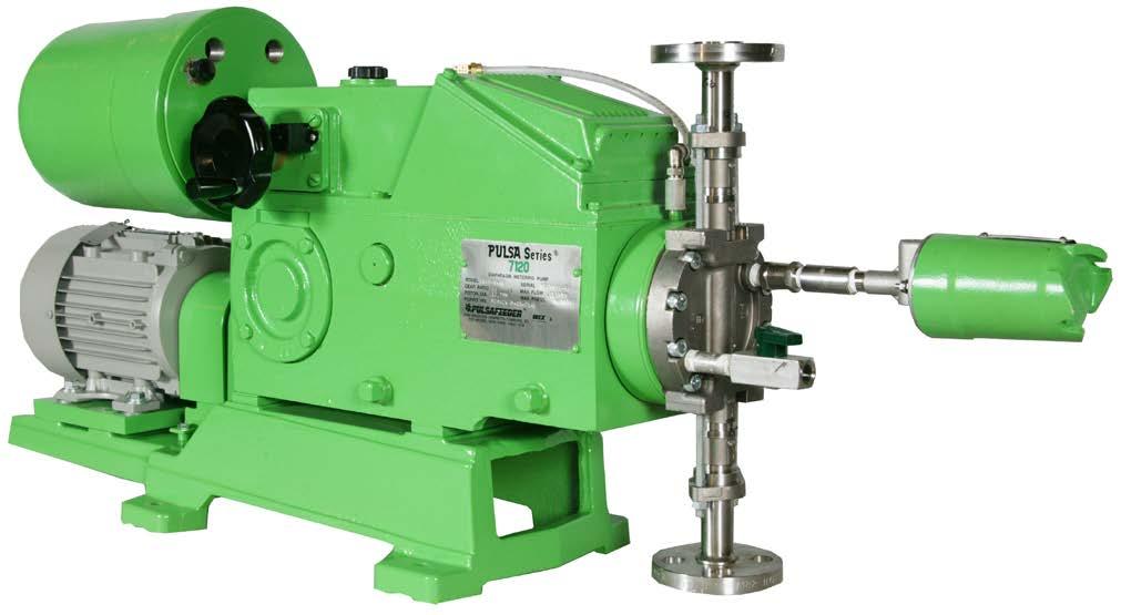
1 INSTALLATION OPERATION MAINTENANCE INSTRUCTION BULLETIN No. 418 i
2 PULSA SERIES GUARANTEE Should you experience a problem with your Pulsafeeder pump, first consult the troubleshooting guide in your operation and maintenance manual. If the problem is not covered or cannot be solved, please contact your local Pulsafeeder Sales Representative, or our Technical Services Department for further assistance. Trained technicians are available to diagnose your problem and arrange a solution. Solutions may include purchase of replacement parts or returning the unit to the factory for inspection and repair. All returns require a Return Authorization number to be issued by Pulsafeeder. Parts purchased to correct a warranty issue may be credited after an examination of original parts by Pulsafeeder. Warranty parts returned as defective which test good will be sent back freight collect. No credit will be issued on any replacement electronic parts. Any modifications or out-of-warranty repairs will be subject to bench fees and costs associated with replacement parts. In addition, Pulsafeeder guarantees its PULSA Series drive assemblies for a period of two years from the date of shipment. All other material and workmanship are fully covered for a period of one year. Any parts found to be defective within the above time span will be replaced free of charge, F.O.B. factory. Equipment or accessories manufactured by others but purchased through Pulsafeeder, such as electric motors, are guaranteed only to the extent of the original manufacturer. Damages incurred from misuse, abuse, and/or improper protection during storage will be cause to void the guarantee. Erosion, corrosion, or improper application of the equipment or related piping by the buyer or any third party is also excluded from the guarantee. The above guarantee is in lieu of any other guarantee, either expressed or implied. We make no warranty of fitness or merchantability. No agent of ours is authorized to make any warranty other than the above. Safety Considerations: 1. Read and understand all related instructions and documentation before attempting to install or maintain this equipment 2. Observe all special instructions, notes, and cautions. 3. Act with care and exercise good common sense and judgment during all installation, adjustment, and maintenance procedures. 4. Ensure that all safety and work procedures and standards that are applicable to your company and facility are followed during the installation, maintenance, and operation of this equipment. Information in this document is subject to change without notice. No part of this publication may be reproduced, stored in a retrieval system or transmitted in any form or any means electronic or mechanical, including photocopying and recording for any purpose other than the purchaser s personal use without the written permission of Pulsafeeder, Inc. ii
3 Table of Contents 1. INTRODUCTION General Description Options Input Signals Control Modes Current Output Signals EQUIPMENT INSPECTION PROCEDURAL NOTES INSTALLATION Wiring Up Start Up CALIBRATION Deadband Adjustment Circuit Board Calibration Meter Readout (current Output) Calibration Auto-Manual Calibration REPAIRS Limit Switch Adjustment Potentiometer Zero Alignment Brake Air Gap Jammed Slider Block ORDERING PARTS CONVERSION (MANUAL TO PULSAMATIC) TROUBLESHOOTING CHART Conventions For the remainder of this bulletin, the following Conventions are in effect. A WARNING DEFINES A CONDITION THAT COULD CAUSE DAMAGE TO BOTH THE EQUIPMENT AND THE PERSONNEL OPERATING IT. PAY CLOSE ATTENTION TO ANY WARNING. Notes are general information meant to make operating the equipment easier. Tips have been included within this bulletin to help the operator run the equipment in the most efficient manner possible. These Tips are drawn from the knowledge and experience of our staff engineers, and input from the field. iii
4 1. Introduction 1.1 General Description The PULSAmatic actuator converts reciprocating motion of the pump into rotary motion to turn the pump s stroke adjustment screw. By selectively engaging either of the two oppositely oriented, one-way clutches, one of two corresponding nuts hat ordinarily rotate freely on a diamond actuator shaft is blocked form rotation when the shaft moves longitudinally in one direction. Thus locked, the nut compels the shaft to rotate, thereby turning the adjustment screw to which it is connected. The actuator assembly consists of the following major components: the actuator shaft (a major portion of which is in the form of a diamond screw), tow brake housings, two one-way clutches, and two helix nuts. Mounted side-by-side, the two brake housings are concentric to the axis of the actuator shaft. The helix nuts are located between the inner walls of the brake housings and the surface of the shaft. One nut engages the right-hand thread of the shaft and other engages the lefthand thread. Each nut rotates within a one-way clutch. In operation, the actuator shaft reciprocates along its axis. When the brakes are de-energized, each nut, along with its respective clutch, is free to rotate in alternation clockwise and counterclockwise directions as it is driven by grooves in the shaft. Under this condition, the shaft and adjustment screw do not rotate. Upon energizing one of the brakes, the corresponding one-way clutch is utilized allowing the nut to rotate only in one direction, while the shaft is moving longitudinally during the e discharge stroke of the pump (linear motion of the shaft is now in the opposite direction), the clutch prevents the nut from rotating, causing the shaft to rotate. This rotation is transmitted by a mechanism inside the gearbox housing to the pump adjustment screw so that the piston stroke length is changed. By energizing the other brake, the adjustment screw is rotated in the opposite direction. To increase or decrease pump output, it is only necessary to selectively energize either brake. Rotary motion of the actuator shaft also rotates a sleeve which in turn drives a gear train through a spur gear pressed on one end of the sleeve. The gear train transfers outputs for a positional feedback potentiometer and limit switches. A bevel gear mounted on the opposite side of the drive sleeve is meshed with a hand wheel bevel gear and mechanical stroke position indicator. A printed circuit board contains standard and optional control circuits. The incoming command signal is compared with the internal feedback signal. If the two are equal or nearly so, no action occurs. If the command signal is greater, one brake is energized, resulting in a corresponding change in pump output (stroke length) and feedback signal. If the feedback signal is greater than the command signal, the other brake is energized, changing the pump output and feedback signal in the reverse direction. When the feedback signal matches the command signal, stroke length is properly positioned and adjustment is halted. The override switch, operable from outside the actuator assembly, disconnects the brakes from the circuit board to permit manual adjustment using the hand wheel. The out position is for manual operation and the in position is for automatic operation.
5 2
6 1.2 Options The PULSAmatic actuator is configured at the factory for a variety of options, both singly and in various combinations. The appropriate wiring diagrams external to the circuit board are included with each pump shipment. 1.3 Input Signals. Standard signals are: 1-5 ma 2000 ohm Impedance 4-20 ma 470 ohm Impedance ma 180 ohm Impedance 0-10 V Greater than 270,000 ohm Impedance Slide wire (Remote, 1000-ohm manual control potentiometer, user-supplied). Actions Direct Acting- minimum and maximum input signal levels correspond directly to minimum and maximum stroke settings respectively. For example, a 4-20 ma signal ranges stroke from zero at 4mA to full at 20 ma. This is the standard mode of action. Reverse Acting- Signal response is inverted relative to direct acting. For example, a 4-20 ma signal ranges stroke from full at 4 ma to zero at 20 ma. This is an optional mode of action. 3
7 1.4 Control Modes Ratio Control- When ratio control is applied, the range of stroke adjustment is proportionally reduced to a level equal to the ratio setting. For example, at a ratio setting of 60%, the full span of the input signal commands the pump to operate between zero and 60% of full stroke rather than over the full range of the stroke. The ratio is manually set between zero and 100% using a remote potentiometer. Split Ranging- A single control signal command s two pumps, each pump responding only to a portion of the total range of the signal. The PULSAmatic controller operates specifically as follows: One pump is commanded from zero to full stroke over the lower half of the input signal, and a second pump is commanded, in the reverse-acting mode, from full to zero stroke over the higher half of the input signal. For example, a 4-20 ma input signal controls the first pump between zero stroke at 4mA to full stroke at 12 ma and controls the second pump between full stroke at 12 ma and zero stroke at 20 ma Manual- Remote manual stroke adjustment potentiometer. Auto-Manual- Remote switch selection between automatic and remote manual operation. 1.5 Current Output Signals 0-10 ma DC 500 ohm Impedance max ma DC 250 ohm Impedance max. 4
8 2. Equipment Inspection 1. Check all equipment for completeness against the order and for shipping damage. Shortages or damage should be reported immediately to your PULSA Series representative. 2. Check pump and PULSAmatic stroke control identification tags for serial and model numbers. There are two tags: one on the pump gearbox which includes the pump model number and another on the PULSAmatic enclosure. The pump gearbox serial number identifies the PULSAmatic actuator as well as any separately mounted control stations. Each should correspond to the information on the parts lists. Use these reference numbers whenever corresponding with the factory. 3. Check the envelope containing this bulletin for service parts list and special drawings and wiring diagrams for specified control options. 3. Procedural Notes Electrical repairs and calibrations should be undertaken only by an electronic technician q2ualified in the maintenance and repair of linear (analog) industrial process control equipment. A digital voltmeter and a process control signal generator are required for electronic calibrations. Troubleshooting and repair may require access to the mechanism linking the actuator control to the oscillating housing inside the pump gearbox. This requires removal and replacement of the rear gearbox cover assembly. Refer to the pump operations manual for the description of these operations. Detailed circuit board schematics, containing component identifications, are available from the factory to facilitate electronic circuit troubleshooting and repair at the board level. The following conventions and procedures apply throughout this bulletin. 1. Zero Stroke refers to a zero, or (000) setting on the mechanical stroke counter. Full Stroke refers to a full or (100) setting on the mechanical stroke counter. 2. A low end input control signal is one that commands the pump to zero stroke A high end input control signal is one that commands the pump to full stroke. Note that the signal values are inverted in the reverse acting option so that, for example, a 4-20 ma signal commands full to zero stroke. In this case, 4 ma is the high end signal. See Options under principals of Operation above for signal definitions. 3. Pump stroke can be manually or automatically set as required for calibrations and adjustments. References to the disable switch ( out for manual, in for automatic) may be omitted. Manual, or hand wheel adjustments made while the pump is not operating, require that pressures be relieved from both the suction and discharge lines. 4. Wiring terminals are indentified on the circuit board and referred to directly. For example TB2-3 refers to terminal No. 3 on Terminal Board No. 2, (reference Figure 4). CAUTION: When troubleshooting, always remove signal potential prior to disconnecting AC power. This will help protect integrated circuits on the circuit board. 5
9 4. INSTALLATION 4.1 Wiring Up (Refer to any special wiring diagrams and installation drawings supplied by Pulsafeeder). AC power lines should be routed to the actuator via a separate conduit from the control signal and any optional accessory wiring. A separate switched and protected circuit is recommended for the actuator power supply. Remove the PULSAmatic actuator cover, which is secured by two screws, or screwed on, in the case of an explosion proof enclosure. The two power transformers should be wired as described by wiring diagrams. Power and ground wire should be No. 18 AWG wire size or larger. A power ground screw is provided on the backing plate near the conduit openings. Terminal TB1-4 is also provided as an optional circuit board ground. This terminal is connected to the circuit board ground through a 4700 ohm resistor. Run the signal and accessory wiring using the alternative conduit opening. No. 22 AWG wire size or larger is recommended. Make all connections per the diagram that apply to the combination of signal and accessories provided. Explosion proof actuators are Underwriters Laboratories (UL) listed and are labeled with the hazardous environments for which they are rated, along with any special installation specifications required in support of UL listing. They must be installed, wired, operated, and maintained in accordance with local electrical codes. CAUTION: To help protect the integrated circuits in the servo amplifier, always energize AC power prior to connecting the signal leads. 4.2 Start Up Ever actuator is adjusted and calibrated at the factory. However, due to variations in input signals RECALIBRATION IS REQUIRED. Prior to performing this procedure (as outlined in the next section) it is recommended that the following steps be followed in order to verify proper mechanical operation and limit switch adjustment. Mechanical Operation- Before applying electrical power, remove the coupling guard between pump and motor and manually rotate the motor shaft through several revolutions. The thin metal brake armatures should rotate in alternate directions as the actuator shaft moves first in one direction and then the other. (If they do not, the actuator linkage may be disconnected from the oscillating housing under the main cover). Replace the motor coupling guard. Limit Switch Verification- with the counter indicating 090 or less, pull out the handwheel and rotate to increase the count. As a value of 200 is approached (from 099 to 100) a faint click should be heard from one of the limit switches. If an audible indication of the limit switch operation cannot be obtained, operation may be verified electrically. Turn the handwheel back to a counter indication of 090 and pull out the override switch. Continuity should exist between the terminals of the limit switch mounted on a double switch bracket, farthest from the printed circuit board. Pull out and slowly rotate the handwheel so that the counter indication increases. The switch should open, indicated by loss of continuity, when the stroke indicator reads between 097 and
10 Operation of the second limit switch (the one closest to the circuit board) may be checked in a similar manner. The limit switch should be open at a stroke indicator reading between 001 and 000. If either of the limit switches appears to be out of adjustment refer to repairs- Limit Switch Adjustment. Barring any problems proceed with Calibrations and Adjustments. Refer also to the Equipment Startup section of the pump Installation, Operation, and Maintenance Instructions. 5. Calibration As stated previously, field recalibration is required upon startup. The following procures are to be performed in sequence as presented. Refer to Figure 4 as required for circuit component locations. 5.1 Deadband Adjustment With pump stroke positioned exactly as commanded by the input signal, a certain change in signal must occur in either direction (increase or decrease) in order to cause the actuator to respond. For example, if a pump is operating at 50% stroke in response to a 50% input signal, the signal must typically increase to 51% or decrease to 49% before the actuator does not respond, or is dead, is called deadband. If deadband is too narrow, the actuator will frequently make slight adjustments in response o small signal variations. In the extreme case, the actuator will continually hunt back and forth over a small range of adjustment. If deadband is too broad, response will lag and accuracy will suffer. The Null potentiometer near the center of the circuit board adjusts deadband. Clockwise movement decreases deadband, increasing sensitivity. Counterclockwise movement increases deadband, decreasing sensitivity. Deadband adjustment for response to a 1% change in signal (depicted in the example above) is appropriate to most installations. This can be set approximately by setting the Null potentiometer in the six o clock position shown in Figure 4. To check deadband adjustment, cycle the pump automatically, by input signal command, to an approximately midrange stroke setting. Leaving the override switch in the in or automatic position, slowly adjust the handwheel in either direction until the actuator responds to return the stroke to the original set point. Care must be taken during this operation, as the handwheel will move without warning. Deadband is observed on the mechanical stroke indicator as the difference between the original stroke setting and that at which the actuator responds. 5.2 Circuit Board Calibration The PULSAmatic circuit senses all control signals in terms of voltage. A current signal is converted to a voltage signal measured across a resistor, provided in the circuit board, through which the current passes. For example, the most commons signal, 4-20 ma DC, passes through a 470 ohm resistor to generate a volt DC signal, (0-6.3 v with Ratio Control). This procedure trims the actuator circuits to the low and high ends of the actual input control signal. 7
11 Without Ratio Control Coarse Adjustment 1. Place the override switch in the out or manual position. The pump need not be running for coarse adjustment. 2. Set up a voltmeter to read a full scale DC voltage of Connect the positive lead of the voltmeter to TB2-2 and the negative lead to TB Set the control signal at the low end (0%) and record the voltage. 5. Set the control signal at the high end (100%) and record the voltage. 6. Set up a voltmeter for DC voltage measurement between TB2-5 (positive) and TB2-1 (common). 7. Adjust the LO trim potentiometer on the circuit board to the voltage recorded in step Set up the voltmeter for DC voltage measurement between TB2-4 (positive) and TB201 (common). 9. Adjust the HI trim potentiometer on the circuit board to the voltage recorded in step The above adjustments are interactive. It may be necessary to repeat steps (2) through (5) several times until the voltages stabilize. This completes coarse adjustment. Without Ratio Control Fine Adjustment 11. With the override switch still in the out or manual position start the pump. 12. Set up a voltmeter for DC voltage measurement between TB2-3 (positive) and TB2-1 (common). 13. Set the control signal at the low end (0%). Move the override switch to the in or auto position. The LO drive LED will light and the pump with automatically adjust to the 0% stroke. 14. Adjust the LO trim potentiometer on the circuit board to the voltage recorded in step (4). The stroke indicator should now read and both LED drive lights should be off. 15. Apply a high end (100%) control signal. Allow the pump to adjust to 100% stroke. 16. With the voltmeter remaining as set up in step (12) above, adjust the HI trim potentiometer to the voltage recorded in step (5). The stroke indicator should now read and again both drive lights should be off. 17. The above adjustments are interactive. It may be necessary to repeat steps (12) through (16) several times until the voltages stabilize. This completes fine adjustment. With Ratio Control (Optional Feature) Coarse Adjustment 1. With the override switch in the out or manual position, start the pump. 2. Set the controls signal at the low end (0%). Move the override switch in to the auto position and allow the pump to adjust to 0%. 3. Place the override switch back in the out or manual position. Check the stroke indicator; if it does not read use the handwheel to manually adjust it to this point. 4. Set the remote ratio control potentiometer at 100%. 5. Set up the voltmeter for DC voltage measurement between TB3-4 (positive) and TB3-6 (common). 8
12 6. Adjust the Ratio Zero potentiometer on the circuit board (to the right of TB3) to +/- 0.0 volts. 7. With the voltmeter remaining as set up in step (5) above, set the control signal at the high end (100%) and record the voltage. 8. Set up a voltmeter for CD voltage measurement between TB2-5 (positive) and TB2-1 (common). 9. Adjust the LO trim potentiometer on the circuit board to +/-0.0 volts. 10. Set up a voltmeter for DC voltage measurement between TB2-4 (positive) and TB2-1 (common). 11. Adjust the HI trim potentiometer on the circuit board to the high end voltage recorded in setup (7) above. 12. The above adjustments are interactive. It may be necessary to repeat steps (8) through (12) several times until the voltages stabilize. This completes coarse adjustment With Ratio Control (Optional Feature) Fine Adjustment 13. With the override switch still in the out or manual position start the pump. 14. Set up a voltmeter for DC voltage measurement between TB2-3 (positive) and TB2-1 (common). 15. Set the control signal at the low end (0%). Move the override switch to the in or auto position. The LO drive LED will light and the pump will automatically adjust to 0% stroke. 16. Adjust the LO trim potentiometer on the circuit board to the voltage recorded in step (6). The stroke indicator should now read and both LED drive lights should be off. 17. Apply a high end (100%) control signal. Allow the pump to adjust to 100% stroke. 18. With the voltmeter remaining as set up in step (14) above, adjust the HI trim potentiometer to the voltage recorded in step (7). The stroke indicator should now read and again both drive lights should be off. 19. The above adjustments are interactive. It may be necessary to repeat steps (12) through (16) several times until the voltages stabilize. This completes fine adjustment. 5.3 Meter Readout Calibration This procedure trims the current output to the calibrated range of pump capacity or stroke. Because the output is based on position of the feedback potentiometer, an input signal is not required for adjustment. Depending on the options ordered an analog meter will have been supplied for signal indication. If not, an amp meter will be required to measure the output, 0-10 ma standard, 4-20 ma optional. 1. With the pump set a zero stroke, adjust the Meter Zero potentiometer on the circuit board (to the left of TB-3, as shown in Figure 4) for zero (0%) meter indication or 0% current level as applicable. Note that with 4-20 ma output the Meter Zero and Range potentiometers will be reversed. 2. Will the pump set at full stroke; adjust the Range potentiometer on the circuit board for 100% meter indication or 100% current level as applicable. 3. The above adjustments are interactive. Repeat steps (1) through (2) several times until the meter accurately indicates both zero and full stroke settings. 9
13 5.4 Auto-Manual Calibration This procedure trims the manual control potentiometer to the low and high ends o the actual input control signal. The main circuit board must be calibrated prior to this procedure. For current type control signals, a resistor is installed across terminals of the auto-manual switch. If present, this resistor must remain in place. This procedure can be performed with the pump on-line and operating, in the manual (handwheel) control mode, with the override switch in the out position. 1. All voltages in this procedure are DC and are measured between TB2-2 (positive) and TB2-1 (common). 2. Set the remote auto-manual selector switch to the Auto position. 3. Set the control signal to the low end and record voltage. 4. Set the control signal to the high end and record voltage. 5. Set the remote selector switch to the manual position. 6. Set the remote percent stroke control potentiometer at zero percent. 7. Adjust the LO trim potentiometer on the small circuit board mounted on the back of the percent stroke potentiometer for the low end voltage recorded in step (3) above. Verify that both LEDS on the main circuit board are off. 8. Set percent stroke potentiometer at 100%. 9. Adjust the HI trim potentiometer on the small circuit board on back of percent stroke potentiometer for high end voltage recorded in step (4) above. Verify that both LEDS on main circuit boards are off. 10. The above adjustments are interactive. It may be necessary to repeat steps 6 through 9 several times, until the voltages stabilize. 10
14 6. Repairs 6.1 Limit Switch Adjustment This procedure adjust the limit switches to prevent the pump mechanism from jamming due to over travel, without significantly restricting the range of stroke length settings. The limit switches disable the actuator from operating below zero strokes or above full stroke, either of which can cause jamming. For this reason, correct limit switch adjustment is very important. The procedure for checking limit switch adjustment is given under Installation- Start Up. As stroke length is manually decreased, the switch closest to the circuit board should open (disabling decrease clutch voltage) at as stroke indicator reading between (001) and (000). This reading must not be below (000). As stroke length is manually increased, the switch farthest from the circuit board should open (disabling increase clutch voltage) at a stroke indicator reading between 099 and 100. This reading must not be above 100. To adjust a limit switch, loosen its two mounting screws, slide it in the required direction and tighten the screws. Verify the adjustment as described under Installation- Start Up. 6.2 Potentiometer 1. Record the color codes of the potentiometer leads to TB2-3, 4, and 5, and disconnect them from TB2. 2. Verify full potentiometer resistance of approximately 1000 ohms between the leads removed from pins 4 and A needle type (analog) meter is recommended for checking potentiometer operation. As the potentiometer gear is turned counterclockwise, the resistance between leads removed from pins 5 and 3 should vary uniformly from zero to approximately 1000 ohms. As the potentiometer gear is turned clockwise, the resistance should vary uniformly from approximately 1000 ohms to zero. 4. If the extreme readings vary significantly from zero and 1000 ohms respectively or if the resistance variation with rotation is not smooth at any point, the potentiometer should be replaced. If the directions of rotation are the reverse of those stated above, then the potentiometer has been wired for reverse acting operation. 5. To replace the potentiometer assembly, assure that pump has been turned manually to the 000 indicator setting. Turn the potentiometer gear full clockwise (see from the gear end) then back counterclockwise ¼ turn. 6. Install the potentiometer and reconnect leads to the circuit board. 11
15 6.3 Zero Alignment The actuator mechanism must be aligned relative to the pump drive in order to permit the full range of stroke adjustment. Preliminary Check 1. Set up a multimeter for resistance measurement across the limit switch (in subassembly #635, Figure 6 or 7) closest to the circuit board. 2. Turn the handwheel clockwise to decrease pump stroke length until the meter indicates an open switch. Record the mechanical stroke indicator reading at this point. Continue decreasing stroke length until resistance is encountered. Record stroke indication at this point as well. If the stroke can be decreased to the resistance point without opening the switch, jump to Step 4. Otherwise proceed with Step If resistance was felt at 000 on the stroke indicator and if the switch opened at a stroke higher than 000 but not above 003, zero alignment is correct and no further action is required. If not, proceed with re-alignment as outlined below. Re-alignment Non-explosion Proof 1. Disconnect the power source to the drive motor and actuator. 2. Remove the screws to the rear gearbox cover, Item #526A. Refer to Figures 8 and Lift the cover slightly and hold the diamond screw shaft Item #657, horizontal to prevent binding. Pull the cover back towards the motor until the shaft is disengaged from the actuator drive sleeve, Item # Check to see that the block, Item #352, inside the oscillating housing, Item #358 is at the top by turning the miter gear Item #357 clockwise. Refer to Figure Set the stroke indicator two digits lower than the setting at which the limit switch opened (see Step 2 of Preliminary Check ). 6. If he diamond shaft is dry, lightly coat it with grease. 7. Hold the cover over the pump and carefully insert the shaft into the actuator drive sleeve as you lower the cover in place. Be sure that the stroke indicator remains as set in Step Replace the cover screws. 9. With the handwheel fully clockwise, the stroke position indicator show read (000). If not, remove the handwheel assembly form the cover assembly, turn to the (000) setting and replace. 10. Align the potentiometer as described under Repairs. 11. Confirm free operation of mechanism and limit switch setup, as described under Installation. Re-alignment Explosion Proof 1. Disconnect the power source to the drive motor and actuator. 2. Remove the screws to the rear gearbox subcover, Item #529A. Refer to Figures 8 and Manually rotate the motor coupling until the oscillating housing is vertical. It may be necessary to remove pressure from the piping system. 12
16 4. Remove the cotter pin, Item #539, nut, Item # 535, and washer, Item #534 from the end of the diamond screw shaft on top of the housing. 5. Remove the screws to the rear gearbox cover, Item #526A. 6. Lift the cover slightly and pull it back towards the motor. As the shaft disengages, the miter gear, Item #533, bushing, Item #532, and bushing pin, Item #538, will come loose. Don t allow them to fall into the gear box. 7. Check to see that the block Item #352, inside he oscillating housing, Item #358, is at the top by turning the miter gear, Item #357, clockwise. Ref to Figure Set the stroke indicator two digits lowers than the setting at which the limit switch opened (See Step 2 of Preliminary Check ). 9. If the diamond shaft is dry, lightly coat it with grease. 10. Hold the cover of the pump and insert the shaft into the housing bore as you lower the cover in place. Make sure that the miter gear, bushing and bushing pin are in place and that the stroke remains as set in Step Replace the washer and nut on the shaft. Snug the nut and then back it off to the nearest hole for insertion of the cotter pin. 12. Replace the cover screws, subcover and coupling guard. 13. With the handwheel fully clockwise, the stroke position indicator should read (000. If not, remove the handwheel assembly from the cover assembly, turn to the (000) setting and replace. 14. Align the potentiometer as described under Repairs. 15. Confirm free operation of mechanism and limit switch setup, as described under Installation. 6.4 Brake Air Gap 1. Check the axial air gaps between the mating halves of the brake and clutch assemblies, Items #638 and #646 on Figures 6 and 7. The gap specifications are inches. 2. If either brake drags without being energized and the gap is less than 10 mils, equally shim all three spacer sleeves, Items #608, to increase the air gap to the specified range. Refer to Figures 6 and 7. Item 607 denotes shim location on the illustrations, but as a spare part. It consists of a pack of six 20-mil shims and twelve 5-mil shims. NOTE: Care must be taken in this adjustment as permanent damage can result. We recommend that all other possible causes listed under Troubleshooting-Brake Slipping be investigated first. 13
17 6.5 Jammed Slider Block 1. The slider block is probably jammed if the stroke cannot be freely adjusted using the handwheel with the override switch pulled out and no pressure load on the pump. To confirm the problem, remove the cover (Item #529A, Figures 8 and 9) over the oscillating housing and observe the position of the front connecting rod, Item #353, where it enters the housing, Item #351 where Figure 5 refers. If the slider block is jammed, the connecting rod will be at the extreme top or bottom position. 2. Two free a jam, turn the slotted nut, Item #535, with the cotter pin, Item #539, remaining in place, using a wrench. (Refer to Figures 8 and 9). If the connecting rod is in the top position, rotate the nut counterclockwise. If the connecting rod is in the bottom position, rotate the nut clockwise. 3. Replace the cover. 7. Ordering Parts When ordering replacement parts, always specify: 1. Pump model and serial number (stamped on the pump nameplate, e.g S-AE with S/N ) 2. The part name and part number from the parts lists. 8. Conversion (Manual to PULSAmatic) Follow these instructions when converting from manual to PULSAmatic stroke adjustment. Numbers in parentheses refer to items as appropriate in Figures 5 through 9, except as noted. Removal of the Existing Manual Control Assembly 1. Disconnect the power supply going to the pump drive motor. Remove the motor coupling guard. 2. Drain out the pump oil into a clean container if it is to be reused or into a suitable container for disposal. 3. Remove the cover screws (530). Pull the cover back toward the motor and lift it off. 4. Inspect the gearbox internal components for broken, missing or worn parts at this time it is advisable to flush any sediment or foreign material from the gearbox, using a suitable solvent. 5. Remove the rear connecting rod cotter pin (#545) and wrist pin (#544). 6. Remove the housing pivot pins (#547). Models 7120 and 7440 Remove the retainer set screws (#546) located directly above the housing pins in the opt surface of the gearbox. NOTE: If slight heat is applied to the pivot pins to loosen paint, or sealant, ensure that no cleaning or combustible fumes or materials are present. 14
18 Models 7660 and 8480 Remove the housing pin flange bolts and thread them into the tapped holes in the flange. Tighten all bolts equally to remove the pins. 7. Pull the housing assembly (#540) rearward until the cross head wrist pin (#550) is exposed. Loosen the set screw (#549) located on the rear of the crosshead (#551), and slide the wrist pin out. Complete removal of the housing assembly is now possible. 8. If a new crosshead is to be used, the existing crosshead can be left on the front connecting rod (#353) and the piston rod unscrewed from the crosshead by placing a wrench on the front connecting rod and the piston rod. One some models it may be necessary to remove the reagent and pump head assemblies in order to remove the piston from the crosshead. If the head assemblies must be removed, refer to the pump Installation, Operation, and Maintenance Instructions for proper repriming instructions, etc. The pump head assemblies are held on to the gearbox by two socket head capscrews located at the 3:00 and 9:00 positions inside the gearbox. Installation of the PULSAmatic Control Assembly 1. Adjust the new oscillating housing assembly (#540) to zero stroke. This is done by turning the miter gear (#357) on the top of the housing assembly until the sliding block (#352) is all the way to the top. 2. Position the new housing assembly in the gearbox. 3. Connect the front connecting rod (#353) into the existing cross head (#551). Ensure that the wrist pin (#550) is centered so that it does not protrude out the sides of the cross head. Secure with the set screw (#549). OR 4. Attach the rear connecting rod onto the housing assembly. 5. Ensure that the pivot pin gaskets are in good condition. Apply a thin coat of sealant. 6. Align the housing to the pivot pin holes and install the pins (#547). On the 7120 and the 7440 pumps, make sure the small reliefs machined into the pins are positioned directly under the set screw holes. 7. Secure by tightening set screws (#546) or flange bolts depending on the model. 8. Adjust the handwheel (#501) on the cover until the stroke indicator (#503) reads Lightly grease the drive shaft (Item #531, Figure 8 or 9) in the diamond groove area. 10. On non-explosion proof models, install the drive shaft assembly onto the housing cap (#358). Hand-tighten the slotted nut (#535), loosen 1 ½ turn to the nearest hole-slot alignment, and insert cotter pin (#539). Assembly cover assembly to pump by carefully threading the drive shaft assembly onto the PULSAmatic control while lowering the cover into place. On explosion proof models, the diamond shaft is retained in the PULSAmatic unit and does not come out so the drive shaft assembly must be fed into the housing cap as the cover assembly is lowered onto the pump. The slotted nut (#535) should be adjusted as above. Access to this nut is provided through small subcover (#529A). 11. Fasten cover to the gearbox making sure cover gaskets (#526B) are positioned properly. Refer to the Installation section for more detailed set-up and wiring information. 15
19 9. Troubleshooting PROBLEM PROBABLE CAUSE Actuator Does Not Adjust Actuator Adjusts to Incorrect Setting Actuator Adjusts in One Direction Only Brake Slipping Erratic Operation 1. No AC power to actuator. 2. Pump not running. 3. Override switch not pushed in. 4. Control signal off, incorrect, or of inverted polarity. 5. Ratio control (if so equipped) set at or very near zero percent. 6. Blown fuse (see Figure 4 for location). 7. Wiring discontinuity. 8. Brake slipping (see Troubleshooting ). 9. Defective feedback potentiometer (see Repairs ). 10. Circuit board malfunction. 11. Broken actuator linkage. 12. Brake drive nut damaged. 1. Control signal incorrect or of inverted polarity. 2. Incorrect ratio control setting (if so equipped). 3. Circuit board out of calibration (if so equipped). (See Calibration ). 4. Actuator misaligned to pump (see Repairs ). 5. Defective feedback potentiometer (see Repairs ). 6. Defective feedback potentiometer (see Repairs ). 7. Limit switch out of adjustment (see Repairs ). 8. Circuit board malfunction. 1. Control signal incorrect or of inverted polarity. 2. Incorrect ratio control setting (if so equipped). 3. Wiring discontinuity. 4. Brake slipping (see Troubleshooting ). 5. Defective feedback potentiometer (see Repairs ). 6. Limit switch out of adjustment (see Repairs ). 7. Circuit board malfunction. 8. Defective brake. 1. Jammed slider block (see Repairs ). 2. Circuit board malfunction (inadequate power to the brake). 3. Brakes misaligned. 4. Improper brake air gap (see Repairs ). 5. Brake friction surface contaminated with oil or other foreign material. 1. Wiring discontinuity. 2. Narrow deadband (see Calibration ). 3. Erratic control signal. 4. Noisy controls signal (check grounding and shielding of controls signal leads). 5. Defective feedback potentiometer (see Repairs ). 6. Brake slipping (see Troubleshooting ). 7. Brake dragging (check brake alignment and air gap, see Repairs ). 8. Circuit board malfunction. 16
20 Figure 5 17 AP00229
21 MODEL 7120/7440 AE HOUSING ASSEMBLY PULSAMATIC CONTROL (Reference Figure 5) ITEM PART NAME QUANTITY 351 Housing Housing Block Connecting Rod-Front Pin Pin Adjustment Screw Miter Gear Housing Cap Assembly Cap Screw Washer Washer Nut Housing Assembly: Consists of all the above components pre-assembled 1 18
22 MODEL 7660/8480 AE HOUSING ASSEMBLY PULSAMATIC CONTROL (Reference Figure 5) ITEM PART NAME QUANTITY 351 Housing Housing Block Connecting Rod-Front Pin Pin Adjustment Screw Miter Gear Housing Cap Assembly Cap Screw Washer Washer Nut Housing Assembly: Consists of all the above components pre-assembled 1 19

23 Figure 6 Standard NEMA 4 ENCLOSURE 20
24 MODEL 7120/7440/7660/8480 NEMA 4 ACTUATOR ASSEMBLY PULSAMATIC CONTROL (Reference Figure 6) AP

25 AP00333 Figure 7 EXPLOSION PROOF ENCLOSURE MODEL 7120/7440/7660/8480 AP


26 NEMA 7 ACTUATOR ASSEMBLY PULSAMATIC CONTROL (Reference Figure 7) 23 AP00335

27 Figure 8 MODELS 7120 AND 7440 MODEL 7120/7440 -AE 24 AP00330
28 CONTROL ASSEMBLY PULSAMATIC CONTROL (Reference Figure 8) ITEM PART NAME QUANTITY 501 Handwheel Set Screw Counter Round Head Screw Counter Gasket Bushing Set Screw Mounting Plate Cap Screw Gasket Gear 48T Gear 16T Set Screw Gear 22T Spacer Washer Washer Cap Screw Insert Miter Gear Set Screw Spring o-ring Pin Roll Pin 1 526A Cover 1 526B Cover Gasket Dip Stick Assembly 1 25
29 529A Breather Cover 1 529B Diaphragm Fillister Head Screw Drive Shaft Assembly Bushing Miter Gear Washer Slotted Nut Actuator Assembly Spacer Pin Cotter Pin Housing Assembly Warning Plate Drive Screw Cap Screw Pin Cotter Pin Set Screw Housing Bolt o-ring Set Screw Pin Crosshead Fillister Head Screw Tube Fitting /7440 PULSAmatic Control consists of all the above components pre-assembled 1 26

30 Figure 9 MODELS 7660 AND AP00331
31 MODEL 7660/8480 -AE CONTROL ASSEMBLY PULSAMATIC CONTROL (Reference Figure 9) ITEM PART NAME QUANTITY 501 Handwheel Set Screw Counter Round Head Screw Counter Gasket Bushing Set Screw Mounting Plate Cap Screw Gasket Gear 48T Gear 16T Set Screw Gear 22T Spacer Washer Washer 1 18 Cap Screw Insert Miter Gear Set Screw Spring o-ring Pin Roll Pin 1 28
32 526A Cover 1 526B Cover Gasket Dip Stick Assembly 1 528A Front Cover 1 528B Diaphragm 1 529A Cover Plate 1 529B Gasket Fillister Head Screw Drive Shaft Assembly Bushing Miter Gear Washer Slotted Nut Actuator Assembly Spacer Pin Cotter Pin Housing Assembly Warning Plate Drive Screw Cap Screw Pin Cotter Pin Hex Head Bolt Housing Bolt Gasket Set Screw Pin Crosshead Fillister Head Screw /8480 PULSAmatic Control consists of all the above components pre-assembled 1 29
33 30 This page is intentionally left blank.

34 31 PSM418 H11
BOLT-ON AND WELD-ON FLUSH FLOOR SLIDEOUT SYSTEMS OPERATION AND SERVICE MANUAL
 BOLT-ON AND WELD-ON FLUSH FLOOR SLIDEOUT SYSTEMS OPERATION AND SERVICE MANUAL TABLE OF CONTENTS SYSTEM...... Warning........ Description...... Prior to Operation OPERATION... Main Components... Mechanical...
Installation, Operation & Maintenance Supplement Instruction. Bulletin No.: IOMS-PUL PULSA Series 7120V DRIVE MOTOR INSTALLATION
 Installation, Operation & Maintenance Supplement Instruction Bulletin No.: IOMS-PUL-1012 PULSA Series 7120V DRIVE MOTOR INSTALLATION Copyright 2001-2015 Pulsafeeder, Inc. All rights reserved. ii Conventions
DC Variable Speed Drive Panel
 DC Variable Speed Drive Panel Installation, Operation & Maintenance Instruction Manual Bulletin #: CC-IOM-0103-D Manufacturers of Quality Pumps, Controls and Systems ENGINEERED PUMP OPERATIONS 2883 Brighton
Fisher 657 Diaphragm Actuator Sizes and 87
 Instruction Manual 657 Actuator (30-70 and 87) Fisher 657 Diaphragm Actuator Sizes 30 70 and 87 Contents Introduction... 1 Scope of Manual... 1 Description... 2 Specifications... 2 Installation... 3 Mounting
Installation Operation Maintenance ADDENDUM BULLETIN No. PS-IOM-HYP-0203-H
 Installation Operation Maintenance ADDENDUM BULLETIN No. PS-IOM-HYP-0203-H USER NOTE: This addendum serves as additional information for Pulsafeeder PULSAR and PULSAR Shadow metering pumps equipped with
Installation Operation Maintenance ADDENDUM
 Installation Operation Maintenance ADDENDUM Bulletin #: PS-IOM-HYPO2-0111-A FACTORY SERVICE POLICY If you are experiencing a problem with your Pulsafeeder pump, first review the IOM, and consult the troubleshooting
SECTION steering mechanism
 07-302.01/ 1 2011MR17 SECTION 07-302.01 GENERAL Description See Figure 1. The includes the steering wheel (1), the steering column, the miter box (3), the steering shafts (2 and 4), and the drag link (7).
Embedded Rack Slide-out System
 Embedded Rack Slide-out System SERVICE MANUAL Rev: 02.16.2017 Page 1 Electric Embedded Rack Slide-out System TABLE OF CONTENTS Safety Information 3 Product Information 3 Operation 4 Extending Slide-Out
ANDCO Eagle Actuator Instruction Manual
 ANDCO Actuators ANDCO Eagle Actuator Instruction Manual The information contained in this manual is essential to safe, successful, long term operation of your Andco Eagle Linear Actuator. Read and follow
GH-BETTIS OPERATING & MAINTENANCE INSTRUCTIONS DISASSEMBLY & ASSEMBLY FOR THE T80X-M4-S DOUBLE ACTING SERIES HYDRAULIC ACTUATORS
 GH-BETTIS OPERATING & MAINTENANCE INSTRUCTIONS DISASSEMBLY & ASSEMBLY FOR THE T80X-M4-S DOUBLE ACTING SERIES HYDRAULIC ACTUATORS -S INDICATES CYLINDERS ARE IN TANDEM PART NUMBER: 100121 REVISION "A" ECN
60 Series End-Mount Brake Instructions Standard Housing
 Bulletin No. BK4655 (04/18) 60 Series End-Mount Brake Instructions Standard Housing Read carefully before attempting to assemble, install, operate or maintain the product described. Protect yourself and
Valtek Auxiliary Handwheels and Limit Stops
 Valtek Auxiliary s and Limit Stops Table of Contents Page 1 General information 2 Installation 2 Side-mounted handwheels, size 25 and 50 (linear actuators) 3 Side-mounted handwheels, size 100 and 200 (linear
I & M MK96 & MK96C. Ideal Installation. Start-Up. Maintenance PROTECT VALVES WITH LINE STRAINERS
 **VIP** If you purchased your MK96 or MK96C Valve, or any stem repair component for this valve, after 9/7/08 - please see **VIP** assembly instruction change on page, middle-right, section. I & M MK96
Electronic Proportional (EP) Control for Heavy Duty Series 0/1 Piston Pumps Model 33 Model 39 Model 46. Model 54 Model 64 Model 76
 Control for Heavy Duty Series 0/1 Piston Pumps Model 33 Model 39 Model 46. Model 54 Model 64 Model 76") Electronic Proportional (EP) Control for Heavy Duty Series 0/1 Piston Pumps Model 33 Model 39 Model 46 Model 54 Model 64 Model 76 Table of Contents Introduction.......................................................
Electronic Proportional (EP) Control for Heavy Duty Series 0/1 Piston Pumps Model 33 Model 39 Model 46 Model 54 Model 64 Model 76 Table of Contents Introduction.......................................................
VA-908x Series Electric Rotary Actuators for Two-Position and Modulating Service
 VA-908x Series Electric Rotary Actuators for Two-Position and Modulating Service Installation Instructions VA-908x Code No. LIT-12011566 Issued August 24, 2009 Applications The VA-908x Series Electric
Eaton Electronic Proportional (EP) Control for Medium Duty Piston Pumps
 Control for Medium Duty Piston Pumps") Eaton Electronic Proportional (EP) Control for Medium Duty 72400 Piston Pumps Table of Contents Introduction....................................................... 3 Identification of Components.........................................
Eaton Electronic Proportional (EP) Control for Medium Duty 72400 Piston Pumps Table of Contents Introduction....................................................... 3 Identification of Components.........................................
Type 657 Diaphragm Actuator Sizes and 87
 Instruction Manual Form 1900 January 2000 Type 657-70 & 87 Type 657 Diaphragm Actuator Sizes 30-70 and 87 Contents Introduction............................... 1 Scope of Manual.............................
Quarter Master Chief Series 92 Actuator
 Quarter Master Chief Series 92 Actuator Installation, Operation and Maintenance Manual File: Series 92 O & M manual Rev. V 4/22/2013 Page 1 of 13 Table of Contents Series 92 Electric Actuator Introduction...
Sofa Slideout Assembly OWNER'S MANUAL. Rev: Page 1 Sofa Slideout Owners Manual
 Sofa Slideout Assembly OWNER'S MANUAL Rev: 06.14.2016 Page 1 Sofa Slideout Owners Manual TABLE OF CONTENTS Warning, Safety, and System Requirement Information 3 Product Information 3 Prior to Operation
Troubleshooting Bosch Proportional Valves
 Troubleshooting Bosch Proportional Valves An Informative Webinar Developed by GPM Hydraulic Consulting, Inc. Instructed By Copyright, 2009 GPM Hydraulic Consulting, Inc. TABLE OF CONTENTS Bosch Valves
Fisher 2052 Diaphragm Rotary Actuator
 Instruction Manual 2052 Actuator Fisher 2052 Diaphragm Rotary Actuator Contents Introduction... 1 Scope of Manual... 1 Description... 1 Specifications... 4 Installation... 4 Actuator Mounting and Changing
ONYX VALVE CO MODEL CAR, CAP-PFO Installation & Maintenance
 ONYX VALVE CO MODEL CAR, CAP-PFO Installation & Maintenance OPERATION: (4-2010) The Onyx series CAR-PFO and CAP-PFO pinch valves fail open on loss of air. The simple spring and air bag arrangement drives
Owner s Manual, Operating Instructions Manual, and Replacement Parts Manual. Lift-Rite Hand Pallet Trucks Model PST Plus
 Owner s Manual, Operating Instructions Manual, and Replacement Parts Manual Lift-Rite Hand Pallet Trucks Model PST Plus This publication, 1269849/001B, applies to the Lift-Rite Hand Pallet Truck, Model
GH-BETTIS SERVICE INSTRUCTIONS DISASSEMBLY & REASSEMBLY FOR MODELS HD521-M4, HD721-M4 AND HD731-M4 DOUBLE ACTING SERIES PNEUMATIC ACTUATORS
 GH-BETTIS SERVICE INSTRUCTIONS DISASSEMBLY & REASSEMBLY FOR MODELS HD521-M4, HD721-M4 AND HD731-M4 DOUBLE ACTING SERIES PNEUMATIC ACTUATORS WITH HYDRAULIC CONTROL PACKAGE PART NUMBER: SE-023 REVISION:
Quarter Master Series 94 Actuator
 Quarter Master Series 94 Actuator Installation, Operation and Maintenance Manual Assembly Series 94 Manual Rev V 9/5/13 Page 1 of 12 Table of Contents Series 94 Electric Actuator Introduction... 3 Description...
Installation Manual. Mixing Box Control Systems Installation, Operation, and Maintenance Manual. 605 Shiloh Road Plano, Texas
 Installation Manual IOM-MBC-00 08-30-04 Mixing Box Control Systems Installation,, and Maintenance Manual Contents Page Introduction...1 General...1 Safety...1 Inspection...1 Mixing Box Control Systems...2
SUREPOWR TM SERIES -SURE 49 FIELD INSTALLATION INSTRUCTIONS
 SUREPOWR TM SERIES -SURE 49 FIELD INSTALLATION INSTRUCTIONS Safety First In the maintenance and operation of mechanical equipment, SAFETY is the basic factor which must be considered at all times. Through
Electronic Proportional (EP) Control for Medium Duty Piston Pumps
 Control for Medium Duty Piston Pumps") Electronic Proportional (EP) Control for Medium Duty 72400 Piston Pumps EP Control for Medium Duty 72400 Piston Pumps Table of Contents Introduction........................................................................
Electronic Proportional (EP) Control for Medium Duty 72400 Piston Pumps EP Control for Medium Duty 72400 Piston Pumps Table of Contents Introduction........................................................................
CONTENTS. VIKING PUMP, INC. A Unit of IDEX Corporation Cedar Falls, IA USA SECTION TSM 710.1
 TECHNICAL SERVICE MANUAL industrial heavy duty motor speed pumps SERIES 4076 AND 4176 SIZES hle, ate and ale SECTION TSM 710.1 PAGE 1 of 8 ISSUE B CONTENTS Introduction....................... 1 Safety
ONYX VALVE CO MODEL DAO-ADA Installation & Maintenance
 ONYX VALVE CO MODEL DAO-ADA Installation & Maintenance OPERATION: (4-2010) The Onyx DAO-ADA pinch valve is an open frame valve without housing enclosure and fails last position on loss of air. This actuator
EG1069X. Generator Electronic Governor Controller Operation Manual
 EG1069X Generator Electronic Governor Controller Operation Manual Smoke Limit Controller Compatible with Barber Colman Dyn1-1069X series *Use for reference purpose only and not a genuine Barber Colman
ELECTRIC BEDROOM SLIDEOUT SYSTEM OPERATION AND SERVICE MANUAL
 ELECTRIC BEDROOM SLIDEOUT SYSTEM OPERATION AND SERVICE MANUAL TABLE OF CONTENTS SYSTEM...... Warning...... Description..... Prior to Operation... System Maintenance..... OPERATION... Warning... Extending
RESISTIVITY MONITOR/CONTROLLERS
 RESISTIVITY MONITOR/CONTROLLERS Installation Operation Maintenance User Manual for Models: 750, 752, 753, 762 2450 Impala Drive Carlsbad, CA 92010-7226 USA Tel: 1-760-438-2021 Fax: 1-800-869-7668 / 1-760-931-9189
CAB TILT HYDRAULIC SYSTEM
 OPERATION, MAINTENANCE and SERVICE INSTRUCTIONS CAB TILT HYDRAULIC SYSTEM WITH POWER-PACKER PUMP, CYLINDERS and LATCHES A division of Actuant Corporation 1-800-745-4142 1 www.powerpackerus.com Notice The
Installation, Operation & Maintenance Manual. Bulletin: IOMS-PUL CHEMAlarm LEAK DETECTIONI
 Installation, Operation & Maintenance Manual Bulletin: IOMS-PUL-1011 CHEMAlarm LEAK DETECTIONI 1 TABLE OF CONTENTS 1. PRINCIPLES OF OPERATION... 3 1.1 General Description... 3 1.2 Process Specifications...
ONYX VALVE CO MODEL DAC-PFO Installation & Maintenance
 ONYX VALVE CO MODEL DAC-PFO Installation & Maintenance OPERATION: (01-10) The Onyx series DAC-PFO pinch valve fails open on loss of air. This simple spring and air bag arrangement that drives a pair of
BETTIS SERVICE INSTRUCTIONS DISASSEMBLY AND REASSEMBLY FOR CB-SR-S SEISMIC SPRING RETURN SERIES PNEUMATIC ACTUATORS
 BETTIS SERVICE INSTRUCTIONS DISASSEMBLY AND REASSEMBLY FOR CB-SR-S SEISMIC SPRING RETURN SERIES PNEUMATIC ACTUATORS PART NUMBER: 102264 REVISION: "C" DATE: November 2000 Page 1 of 11 1.0 INTRODUCTION 1.1
MM1/MM2 INSTALLATION & MAINTENANCE INSTRUCTIONS
 MM1/MM2 INSTALLATION & MAINTENANCE INSTRUCTIONS DESCRIPTION / IDENTIFICATION The MM series proportional control valves utilize ProportionAir's unique closed loop control technology for superior control
Maintenance Instructions
 General Note These instructions contain information common to more than one model of Bevel Gear Drive. To simplify reading, similar models have been grouped as follows: GROUP 1 Models 11, 0, 1,, (illustrated),,
ONYX VALVE CO MODEL DAO-PFC Installation & Maintenance
 ONYX VALVE CO MODEL DAO-PFC Installation & Maintenance OPERATION: (4-2010) The Onyx DAO-PFC pinch valve is an open frame valve without housing enclosure and fails closed on loss of air. The actuator drives
Powers TM Controls EA 338 Electronic Actuator
 Powers TM Controls Technical Instructions Document No. 155-136P25 EA 338-1 Description Features 24 Vac power supply. The s are used with floor mount linkage kits to operate dampers in HVAC installations.
Electronic Proportional (EP) Control for Heavy Duty Series 2 Piston Pumps Model 33
 Control for Heavy Duty Series 2 Piston Pumps Model 33") Electronic Proportional (EP) Control for Heavy Duty Series 2 Piston Pumps Model 33 Model 39 Model 46 Model 54 Model 64 EP Control for Heavy Duty Series 2 Piston Pumps Table of Contents Introduction........................................................................
Electronic Proportional (EP) Control for Heavy Duty Series 2 Piston Pumps Model 33 Model 39 Model 46 Model 54 Model 64 EP Control for Heavy Duty Series 2 Piston Pumps Table of Contents Introduction........................................................................
ONYX VALVE CO MODEL DAO-PFO Installation & Maintenance
 ONYX VALVE CO MODEL DAO-PFO Installation & Maintenance OPERATION: (4-2010) The Onyx DAO-PFO pinch valve is an open frame valve without housing enclosure and fails open on loss of air. The actuator drives
12 Series Linear Actuators. Operation & Maintenance Manual, Analog Positioner Installation
 12 Series Linear Actuators Operation & Maintenance Manual, Analog Positioner Installation 6810 POWERLINE DR.-FLORENCE, KY. 41042 - TELEPHONE 859-727-7890, TOLL FREE 1-800-662-9424 FAX. 859-727-4070, E-MAIL:
INSTALLATION, OPERATION AND MAINTENANCE MANUAL (IOM)
") INSTALLATION, OPERATION AND MAINTENANCE MANUAL (IOM) IOM-1088 03-16 Model 1088 Vacu-Gard Blanketing Valve ISO Registered Company SECTION I I. DESCRIPTION AND SCOPE The Model 1088 Vacu-Gard is a tank blanketing
INSTALLATION, OPERATION AND MAINTENANCE MANUAL (IOM) IOM-1088 03-16 Model 1088 Vacu-Gard Blanketing Valve ISO Registered Company SECTION I I. DESCRIPTION AND SCOPE The Model 1088 Vacu-Gard is a tank blanketing
CBC-300 Series & CBC-300C Series Dual Channel Adjust Clutch/Brake Controls
 CBC-300 Series & CBC-300C Series Dual Channel Adjust Clutch/Brake Controls P-269-89-0408 Installation Installation & Operating Instructions Contents Introduction........................... 2 Specifications.........................
Servo and Proportional Valves
 Servo and Proportional Valves Servo and proportional valves are used to precisely control the position or speed of an actuator. The valves are different internally but perform the same function. A servo
MCV106A. Hydraulic Displacment Control-PV DESCRIPTION FEATURES ORDERING INFORMATION. BLN Issued: March 1991
 DESCRIPTION MCV106A Hydraulic Displacment Control-PV Issued: March 1991 The MCV106A Hydraulic Displacement Control (HDC) is a costeffective hydraulic pump stroke control which uses mechanical feedback
Installation Manual For ISL98, ISL03, ISL07, ISC07
 Installation Manual For ISL98, ISL03, ISL07, ISC07 Table of Contents Section 1: Introduction... 3 Housing Identification... 3 Engine Identification... 3 Special Tools... 3 Automatic Transmissions... 3
Service Manual. Climate Control Inc.
 SECTION 2 Service - Clutch Servicing (Removal & Installation) - Shaft Seal Servicing (Removal & Installation) - Head & Valve Plate Servicing (Removal & Installation) - Baseplate Servicing (Removal & Installation)
Filtered PWM Speed Control for Permanent Magnet DC Motors
 Instructions for Installation and Operation Filtered PWM Speed Control for Permanent Magnet DC Motors Model 0794 Speed and Direction Control up to 5/8 HP NEMA-1/IP-20 Specifications Product Type:... WPM-2148E1
CONTROL FEATURES AVAILABLE OPTIONS
 Vari Speed A2000 TABLE OF CONTENTS Control Features Options Application Data Operating Condition s Control Ratings Chart Mounting Dimensions Installation and Wiring Typical Wiring Diagram Schematic (Block
p.t.o. Slip clutch Read this material before using this product. Failure to do so can result in serious injury. Save this manual.
 p.t.o. Slip clutch 65517 Installation Instructions Distributed exclusively by Harbor Freight Tools. 3491 Mission Oaks Blvd., Camarillo, CA 93011 Visit our website at: http://www.harborfreight.com Read
Instruction Manual PN-Z PACKED PLUNGER PUMP. This Manual should be made available to person responsible for installation, maintenance and operation.
 MILTON ROY INDIA (P) LTD Metering Pumps Instruction Manual PN-Z PACKED PLUNGER PUMP This Manual should be made available to person responsible for installation, maintenance and operation. PUMP MODEL: SERIAL
Reproduction or other use of this Manual, without the express written consent of Vulcan, is prohibited.
 SERVICE MANUAL ELECTRIC BRAISING PANS (30 & 40 GALLON) VE30 VE40 ML-126849 ML-126850 VE40 SHOWN - NOTICE - This Manual is prepared for the use of trained Vulcan Service Technicians and should not be used
PEAKTRONICS DMC-101 ADDITIONAL FEATURES. DC Motor Controller, 5A DMC-101
 PEAKTRONICS The Peaktronics DC Motor Controller is used for proportional positioning of actuators that use either DC motors or DC solenoids. The wide operating range of the (10 to 30 VDC and loads up to
Tooling Assistance Center
 Safeguards are designed into this application equipment to protect operators and maintenance personnel from most hazards during equipment operation. However, certain safety precautions must be taken by
Table of Contents Visual Inspection and Neutralizing... 3 Disassembly
 1 Table of Contents Visual Inspection and Neutralizing... 3 Disassembly... 3... 4... 4 Cleaning... 4 Inspection... 4 Reconditioning of Valve Seats... 5 Lapping Procedures... 5 Lapping Blocks... 5 Lapping
STYLE 9300 FLOW/PRESSURE METER INSTALLATION & OPERATING INSTRUCTIONS
 STYLE 9300 FLOW/PRESSURE METER INSTALLATION & OPERATING INSTRUCTIONS INTRODUCTION The Style 9300 Flow/Pressure Meter from Akron is designed to offer reliable and accurate service with an easy to install,
Series 44 Installation Instructions
 and field service checklist Series 44 Installation Instructions Table of Contents Page 1 Page 2 & 3 Page 4 Page 5 Page 6 Page 7 Page 8 System Components Amplifiers System Components Introduction and Dimensions
th Street, Surrey, B.C. Canada V3W 0A6 Telephone Fax July 2012
 8238-129 th Street, Surrey, B.C. Canada V3W 0A6 Telephone 604-572-3935 Fax 604-590-8313 http://www.kobelt.com 7173-KAS MANUAL July 2012 Leaders in Quality Marine Controls, Steering Gear, and Disc Brakes.
Installation and Service Instructions for Self Adjust Brakes 81,000 Series
 Spring-Set Disc Brakes P/N -07-9-00 effective 07/0/0 Installation and Service Instructions for Self Adjust Brakes,000 Series Current revision available @ www.stearns.rexnord.com Tools required for installation
M9106-AGx-2N0x Series Electric Non-spring Return Actuators
 Installation Instructions M9106AGx-2N0x Issue Date 08/31/01 M9106-AGx-2N0x Series Electric Non-spring Return Actuators Installation IMPORTANT: The M9106-AGx-2N0x Series actuator is intended to control
Maintenance Information
 04581245 Edition 2 May 2014 Air Grinder, Die Grinder and Sander Series G2 (Angle) Maintenance Information Save These Instructions Product Safety Information WARNING Failure to observe the following warnings,
Maintenance Information
 45528270 Edition 1 June 2007 Barring Motor T480 Series Maintenance Information Save These Instructions WARNING Always wear eye protection when operating or performing maintenance on this Barring Motor.
User s Manual OM th edition
 FloWing Eccentric Rotary type Control Valves Model: VFR (1, 1½, 2 inches) User s Manual OM2-8130-0300 5th edition Copyright, Notices and Trademarks 2012 Azbil Corporation All Rights Reserved. While this
RF Point Level Control with Sensor Monitor
 The 681 Point Level Control utilizes DPDT relays to provide switching for peripheral devices (such as pumps) in level applications. A sensor attached to the control acts as an antenna to transmit the process
MICRO WELD MODEL DP1 & DP2 HEAVY DUTY NON-FERROUS BUTT WELDERS MICRO PRODUCTS COMPANY SERVICE MANUAL
 MICRO WELD MODEL DP1 & DP2 HEAVY DUTY NON-FERROUS BUTT WELDERS MICRO PRODUCTS COMPANY SERVICE MANUAL 1 TABLE OF CONTENTS 1.0 SPECIFICATIONS 2.0 GENERAL OPERATING INSTRUCTIONS 3.0 BASIC OPERATING PARTS
MODULATING SERVICE ELECTRIC ACTUATORS OPERATION AND MAINTENANCE MANUAL COMMERCIAL AND INDUSTRIAL VALVES AND AUTOMATION
 SERIES 000/S-X MODULATING SERVICE ELECTRIC ACTUATORS OPERATION AND MAINTENANCE MANUAL COMMERCIAL AND INDUSTRIAL VALVES AND AUTOMATION Publication S000X- VER045- For information on this product and other
Operation and Maintenance Manual for. Joyce/Dayton Linear Actuator Pound Capacity AC Actuator (with limit switch and potentiometer)
") Joyce/Dayton Corp. Operation and Maintenance Manual for Joyce/Dayton Linear Actuator 1500 Pound Capacity AC Actuator (with limit switch and potentiometer) WARNING! The recommendations in this manual for
Joyce/Dayton Corp. Operation and Maintenance Manual for Joyce/Dayton Linear Actuator 1500 Pound Capacity AC Actuator (with limit switch and potentiometer) WARNING! The recommendations in this manual for
Pro-Series/ Electromechanical Linear Actuator
 Pro-Series/ Electromechanical Linear Actuator Installation and Operation Manual P-264-PROSERIES (08/10) Keep all product manuals as a product component during the life span of the product. Pass all product
ENC 150 REFERENCE MANUAL ACU-RITE
 ENC 150 REFERENCE MANUAL ACU-RITE ENC150 Page Introduction... 2 Mounting Preparation... 3 Mounting Information... 4 Encoder Dimensions... 5 Backup Spar Dimensions... 6 Mounting Requirements... 7 Typical
3-PHASE SMART CONTROLLER STP-SCIIIC INSTALLATION GUIDE
 3-PHASE SMART CONTROLLER STP-SCIIIC INSTALLATION GUIDE The information in this publication is provided for reference only. While every effort has been made to ensure the reliability and accuracy of the
Surepowr Series 100 Installation Manual
 Surepowr Series 100 Installation Manual Safety First In the maintenance and operation of mechanical equipment, safety is the basic factor which must be considered at all times. Through the use of the proper
EV-2051-M Electric Motor. Operation and Maintenance Manual
 EV-2051-M Electric Motor Operation and Maintenance Manual Table of Contents Safety... 3 General...3 Safety Notices...6 Cautions, Warnings and Dangers...7 Cautions...8 Warnings...11 Dangers...13 Important
Maintenance Information
 80234313 Edition 1 June 2006 Air Grinder, Die Grinder, Sander and Belt Sander Series G1 (Angle) Maintenance Information Save These Instructions WARNING Always wear eye protection when operating or performing
CBC-300 & CBC Series Dual Channel Adjust Clutch/Brake Controls
 CBC-300 & CBC-300- Series Dual Channel Adjust Clutch/Brake Controls P-205-WE 89-0549 Installation & Operating Instructions An Altra Industrial Motion Company Contents Introduction... 2 Specifications...
WALKIE HIGH LIFT HYDRAULIC SYSTEM
 WALKIE HIGH LIFT HYDRAULIC SYSTEM W30-40ZA [B453]; W20-30ZR [B455]; W25-30-40ZC [B454] PART NO. 1524251 2000 SRM 1025 SAFETY PRECAUTIONS MAINTENANCE AND REPAIR When lifting parts or assemblies, make sure
DENISON HYDRAULICS open loop pump controls series P140 A-mod, P260 B-mod service information
 DENISON HYDRAULICS open loop pump controls series P10 A-mod, P260 B-mod service information Publ. S1-AM02-A replaces S1-AM02 01-97 CONTENTS typical characteristics-------------------------------------------------------------------------------
HexPro Series Low Profile Wrenches
 HexPro Series Low Profile Wrenches Operation and Maintenance Manual Model 2HP 4HP 8HP 14HP 30HP www.torquetoolsinc.com Use the HEXPRO Series Low Profile Wrenches Model 2HP 4HP 8HP 14HP 30HP to install
BALDOR MN413 Brakes Manual
 BALDOR MN413 Brakes Manual http://www.manuallib.com/baldor/mn413-brakes-manual.html The DODGE D-Series motor brakes are manufactured to NEMA standards for mounting to C-face and double shafted motors.
RUFNEX Series Low Profile Wrenches Operation and Maintenance Manual
 RUFNEX Series Low Profile Wrenches Operation and Maintenance Manual http://www.torsionx.com Use the RUFNEX Series Ultra-Low Profile Wrenches to install and remove large bolts that have minimal wrench clearance.
DIGITAL GLYCOL FEEDER
 DIGITAL GLYCOL FEEDER DGF1, DGF2 OPERATING INSTRUCTIONS P/N: 72-900-24 Rev J (06-22-07) Manufactures of Quality Pumps, Controls and Systems STANDARD PUMP OPERATION 27101 Airport Road Punta Gorda, FL 33982
APCO CRF-100A RUBBER FLAPPER SWING CHECK VALVES
 APCO CRF-100A RUBBER FLAPPER SWING CHECK VALVES Instruction D12043 June 2016 DeZURIK Instructions These instructions provide installation, operation and maintenance information for APCO CRF-100A Rubber
MOTORIZED FOLDING CAMPER WINCH
 OWNER'S MANUAL MOTORIZED FOLDING CAMPER WINCH With 1200lb Lift Capacity The 12 Volt Motorized Folding Camper Winch is used to raise and lower folding campers with the touch of the switch, eliminating hand
Electro-Brake 375, 475, 650, 825, 1000, 1225
 Electro-Brake 375, 475, 650, 825, 1000, 1225 P-211-WE 819-0043 Installation Instructions An Altra Industrial Motion Company Contents Installation Instructions.... 2 Electrical Coil Data.... 5 Burnishing
Standard Valves Series Globe Valves Series Angle Valves Series Way-Valves
 Installation, Operation, Maintenance Instructions Standard Valves Series 035 000 Globe Valves Series 031 000 Angle Valves Series 033 000 3-Way-Valves 1 GENERAL INFORMATION These instructions are designed
User Manual. T6 Tachometer. Online: Telephone: P.O. Box St. Petersburg, Florida 33736
 User Manual T6 Tachometer Online: www.phareselectronics.com Telephone: 727-623-0894 P.O. Box 67251 St. Petersburg, Florida 33736 Table of Contents Overview... 1 Description... 1 Wiring... 1 T6 Tachometer
SPECIFICATIONS ATTENTION OPERATION DESCRIPTION
 EMP-5 Installation Manual - P/N 80103 - Ed. 01/09 EMP-5 Current or Voltage Input Drive Modulating Actuator Installation Instructions 1 7 SPECIFICATIONS The EMP-5 series actuators provide damper control
Instructions for Installing and Operating Clark Reliance EA100 Series Levalarm
 Section: R500.532F Bulletin: 532F Date: 7/1/2015 Supersedes: 532E Instructions for Installing and Operating Clark Reliance EA100 Series Levalarm This manual covers the following model numbers: EA100D,
Ideal Installation. I & M Mark 67 (1/2 6 ) Control Line. Installation & Maintenance Instructions for Mark 67 Pressure Regulators
 Control Line. Installation & Maintenance Instructions for Mark 67 Pressure Regulators") I & M Mark (/ ) 0 Wasson Road Cincinnati, OH 0 USA Phone --00 Fax -8-00 info@richardsind.com www.jordanvalve.com Installation & Maintenance Instructions for Mark Pressure Regulators Warning: Jordan Valve
I & M Mark (/ ) 0 Wasson Road Cincinnati, OH 0 USA Phone --00 Fax -8-00 info@richardsind.com www.jordanvalve.com Installation & Maintenance Instructions for Mark Pressure Regulators Warning: Jordan Valve
 Operation and Maintenance Manual http://www.torsionx.eu Use the MaxDrv Series Square Drive Torque Wrench Model.75, 1, 3, 5, 8, 10, 20, 25, 35, 50 to install and remove threaded fasteners requiring precise
CONTROL VALVES. Installation, Maintenance & Operating Instructions. Read these instructions carefully before installation or servicing.
 KOSO HAMMEL DAHL CONTROL VALVES KOSO HAMMEL DAHL 253 Pleasant Street West Bridgewater, MA 02379 tel: 774.517.5300 fax: 774.517.5230 www.hammeldahl.com Installation, Maintenance & Operating Instructions
Fisher 3024C Diaphragm Actuator
 Instruction Manual 3024C Actuator Fisher 3024C Diaphragm Actuator Contents Introduction... 1 Scope of Manual... 1 Description... 2 Specifications... 3 Installation... 5 Mounting the Actuator on the Valve...
ARKAL SCREEN LINE H - SERIES Hydraulically Operated Self-Cleaning Screen Filter SERVICE & MAINTENANCE MANUAL
 ARKAL SCREEN LINE H - SERIES Hydraulically Operated Self-Cleaning Screen Filter SERVICE & MAINTENANCE MANUAL Table of Contents Subject Page No. Introduction... 2 Safety Instructions... 3 Description &
ROM Series. Keeping the World Flowing. Installation Manual. Valve Actuators
 ROM Series Installation Manual Valve Actuators Keeping the World Flowing Contents Section Page Health and safety 3 Storage 4 Mounting the actuator 4 Setting the actuator stop bolts 5 Cable connections
M9216 Series Electric Spring Return Actuators
 *34636461G* 34-636-461, Rev. J Installation Instructions M9216 Issue Date October 217 M9216 Series Electric Spring Return Actuators Installation IMPORTANT: The M9216 Series actuator is intended to control
OPERATION AND MAINTENANCE MANUAL
 WREN IBT SERIES HYDRAULIC TORQUE WRENCHES IBT SQUARE DRIVE SERIES OPERATION AND MAINTENANCE MANUAL FOR WREN Products: POINT 75, 1IBT, 3IBT, 5IBT, 8IBT, 10IBT, 20IBT, 25IBT, 35IBT, 50IBT SQUARE DRIVE HYDRAULIC
RELEASING PRESSURE IN THE HYDRAULIC SYSTEM,
 Testing And Adjusting Introduction NOTE: For Specifications with illustrations, make reference to SPECIFICATIONS for 225 EXCAVATOR HYDRAULIC SYSTEM, Form No. SENR7734. If the Specifications are not the
Low Profile Wrenches Operation and Maintenance Manual
 Low Profile Wrenches Operation and Maintenance Manual http://www.torquetoolsinc.com Use the HEXPRO Series Low Profile Wrenches Model 2HP 4HP 8HP 14HP 30HP to install and remove large bolts that have minimal