L-120 SERIES INSTRUCTION AND MAINTENANCE MANUAL
|
|
|
- Jonas McBride
- 5 years ago
- Views:
Transcription

1 L-20 SERIES INSTRUCTION AND MAINTENANCE MANUAL BULLETIN 2002 ISSUE 5/-REV-00 A Product of Limitorque India Ltd. Please before you attempt to install or operate your Limitorque Actuator be sure to read this booklet at least once. Always keep it available for quick reference.
2 LIMITORQUE TYPE L-20 INSTRUCTION & MAINTENANCE MANUAL Your Limitorque Valve Control... Limitorque's L-20 series of actuators is the most advanced valve control on the market... the result of many years of development and an awareness of our customer's requirements. This booklet has been prepared to help you obtain the most benefit from the equipment. It contains instructions on the installation and maintenance of the units, plus helpful suggestions to enable you to become thoroughly familiar with the location and proper use of the operating controls. Limitorque actuators control the opening and closing of the valve and limit the torque and thrust applied to the valve stem. As a result, all valve operating components are protected from overload, improper seating or pipe line obstructions. Limitorque controllers may be mounted on any size of valve in almost any position or location. They are readily adaptable to existing equipment.
3 PRINCIPLES OF OPERATION Description of Motor Operation: Your Limitorque actuator is always for motor operation whenever the motor is energized. DO NOT FORCE THE DECLUTCH LEVER INTO MOTOR OPERATION POSITION - THE LEVER RETURNS TO THIS POSITION AUTOMATICALLY WHEN THE MOTOR IS ENERGIZED. (REFER TO PAGE 6) In motor operation, the motor gear set (#'s 35 to 38) drives the worm shaft (#5) and worm gear (#2) which in turn rotates the clutch sleeve (#9) by means of driving lugs. The clutch sleeve and worm gear may be assembled to produce either a 'no lost motion or 'hammer blow' effect. The drive sleeve (#25) is keyed to the clutch sleeve and, hence, rotates producing the required output rotary motion. Description of Manual Operation: PLEASE NOTE THAT THE SHIFT FROM MANUAL TO MO- TOR OPERATION IS AUTOMATIC AND DOES NOT REQUIRE EXTERNAL POSITIONING OF THE DECLUTCH SHAFT. Torque and Travel Limiting: The geared limit switch is driven by a bevel gear connected to the upper drive lugs of the clutch sleeve. Thus the limit switch is directly connected to the output of the actuator and, once properly set, remains in step with the valve position regardless of electric or manual operation of Limitorque actuator. The worm and worm shaft are supported in two rotating spring packs. As torque is generated by the actuator, the worm moves axially against one of the spring packs. Each pack is pre-calibrated and hence, a finite compression represents a finite torque output. Movement of the worm operates the torque switch which interrupts the power of the motor. The torque switch is adjustable and can be set to operate at predetermined torque levels. Lubrication : Limitorque actuators are designed with a totally sealed gear case factory-packed with grease. The gear case can be mounted in any position (as all penetrations into it are sealed); however, those mounting positions which would cause vulnerable areas of the operator (e.g., Motor, or switch compartment) to be saturated with lubricant should a seal failure occur, should be avoided if possible. No seal can remain absolutely tight at all times; therefore, it is not unusual to find a very small amount of weeping around shaft seals - especially during long periods of idleness such as storage. The use of grease minimizes this condition. Should a small amount of weeping be found on start-up, it should be removed with a clean rag. Once the equipment has begun operating, this phenomenon should disappear. Factory Lubricants: Gear Case : Geared Limit : Switch Counterclockwise rotation of the declutch lever (#9) causes the declutch actuator to lift the clutch sleeve out of engagement with the worm gear. Drive lugs on top of the clutch sleeve engage matching lugs in the handwheel adapter (#26) and, then, latches engage the clutch sleeve in this position. The actuator is now in the handwheel drive option. Energizing the motor at this point will cause the latches to drop out and the spring loaded clutch sleeve re- engages with the lugs on the worm gear. The Actuator is once more in motor operation. SERVOGEM EP0 OKS40 MoS2 high Performance Grease of OKS speciality lubricants Lubricants Inspection: It is recommended that all Limitorque actuators be inspected for proper lubrication prior to operating especially if they have been stored for a long period of times. The freuency of lubrication inspections should be based upon historical data on the installed equipment. Every operator application has its own effect on lubricants and each facility should pattern its inspections around its particular needs. The following schedule of lubrication inspection should be followed until operating experience indicated otherwise. Main Gear Case: Inspect lubrication every 8 Months. Geared Limited Switch : Inspect lubricant every 36 months. 2
4 INSTALLATION TIPS Caution : Do not attempt to store, install or operate your Limitorque Valve Contol without reading the instructions and cautionary notes below. Caution : Do not remove the unit mounting bolts when the unit is mounted on a rising stem valve unless the valve is in the fully open position, or there is not, nor cannot be, any pressure in the line. Note : Limit switches are not factory set by Limitorque. They must be set when the unit is installed on the valve. Short Term Storage (Less than one year) 6. Use protective stem cover, check valve stem travel and clearance before mounting covers on rising stem valves. 7. Set up periodic operating schedule for infrequently used valves. 8. Keep the valve stem clean and lubricated. 9. Reset the travel limit switches prior to motor operation if the unit has been dismantled or removed from the valve. Caution : Shut off incoming power before opening switch compartment. DO NOT :. Caution : Do not attempt to work on your Limitorque actuator without first shutting off incoming power. 2. Do not attempt to work on your Limitorque actuator while it is mounted on a torque seated valve. 3. Do not motor operate the valve without first setting or checking the limit switch and motor rotation direction. UNITS ARE NOT FULLY WEATHERPROOF UNTIL PROP- 4. DO NOT FORCE THE DECLUTCH LEVER INTO ERLY INSTALLED ON THE VALVE OR PREPARED FOR MOTOR OPERATION LEVER WILL AUTOMATICALLY STORAGE. Units should be stored in a clean, dry, protected warehouse free from excessive vibration and rapid temperature changes. If the units stored outside, they must be stored off the ground, high enough to prevent their being immersed in water or buried by snow. Connect the internal heaters (if supplied) or place dessicant in the switch compartment. Replace all plastic caps or plugs with pipe plugs and ensure that all covers are tight. If the unit is mounted on a valve and the stem protrudes from unit, a suitable stem cover must be provided. Unit should be stored with the motor and switch compartment horizontal. FAILURE TO COMPLY WITH THESE RECOMMENDED STORAGE PROCEDURES WILL VOID THE WARRANTY. FOR LONGER TERM STORAGE PLEASE CONSULT L I M I T O R Q U E F O R P R O C E D U R E S A N D RECOMMENDATIONS. DO :. Mount motors on a horizontal plane, if possible. 2. Keep the switch compartment clean and dry. 3. Operate the unit by handwheel only, when initially setting the limit switches. 4. Check all unit wiring to ensure that it coincides with the applicable wiring diagram. 5. Carefully check for correct motor rotation direction. If the motor is driving the valve in the wrong direction, interchange any two leads on three phase motors. RETURN TO MOTOR OPERATION WHEN MOTOR IS ENERGIZED. 5. DO NOT FORCE DECLUTCH LEVER INTO HAND OPERATION. IF THE CLUTCH DOES NOT EASILY ENGAGE, ROTATE HANDWHEEL SLOWLY WHILE OPERATING THE DECLUTCH LEVER. 6. Do not use abrasive cloth to clean the contacts on the limit and torque switches. 7. Do not torque seat 90 operation valves nor run them against the stops as this may cause damage to the valves. 8. Do not alternately start/stop the motor to open or close a valve which is too tight for normal operation. 9. Do not reset torque switch to a setting higher than the recommended factory maximum. 0. Do not attempt to repair gearing in the limit switch. Replace entire gear frame assembly if necessary. 3
5 TORQUE SWITCH CAUTION : Disconnect all incoming power before opening limit switch compartment or working on the torque switch. If the torque switch has been removed from the unit or if a new torque switch is being installed, the torque switch must be rebalanced using the following procedure :. Ensure that the unit is in manual mode and load is removed from the wormshaft spring pack. The torque switch is designed to protect the actuator in open 2. Prior to reinstalling the torque switch, note the open and and close directions. The switch was set at the factory close torque switch settings. according to information regarding necessary torque or thrust 3. Loosen screws (A) and position both pointers (B) at the output that was provided at the time of order # setting, tighten screw (A). In this position the index marks should be aligned. Loosen balancing screws and CAUTION : A maximum stop setting plate is provided on most install the torque switch when properly installed, the base units. Do not remove this plate. Do not exceed the setting of the torque switch should be flush against the indicated by this limiter plate without contacting Limitorque. compartment and the hole for the mounting screw should Torque Switch Setting Procedure be aligned. Install the mounting screw. 4. Tighten the balancing screws. The switch is now balanced and ready for the pointers to be returned to their Before adjusting or installing a torque switch, place the L20 unit in manual mode and release the load on the worm shaft spring pack. CAUTION : Installing or adjusting the torque switch with the operator in a loaded condition will result in a loss of torque protection. Should the present switch setting require changing, proceed follows : For both open or close direction, loosen screw (A) and move pointer (B) to desired position. A higher number indicates a high torque and/or thrust output. 2. Tighten screw (A). 3. Operate the valve electrically to seat valve and to ensure tight shut-off. original settings. CAUTION : The balancing screws should not be touched except during the balancing procedure. BALANCING PROCEDURE (fig-) 4
6 GEARED LIMIT SWITCH CAUTION : The geared limit switch is not preset at the factory and must be adjusted after the actuator has been mounted on its associated equipment. CAUTION: When setting the limit switch rotor segments (cams) using a variable speed electric drill, do not run drill at speeds higher than 200 RPM. Operating the drill at high speeds can damage the gearing within the limit switch. Disconnect all incoming power to the unit prior to opening the 6. Push in setting rod (A) and turn one quarter turn. The rod limit switch compartment and adjusting the switch. will latch in this depressed position. CASE-I:- Trip contacts/end position contact is Consult the relevant wiring diagram for limit switch contact closed (Generally required if UEC-3 family (fig-2) development. All L20 units are supplied with 8 contact limit controller is supplied) switches-4 switches on each of 2 rotors. Two rotors are used A If contact is Normally Open (NO):- for end of travel indication. Rotate the intermediate gear shaft in same direction as noted in Page No. 2 until it becomes normally close (NC) Limit Switch Setting Procedure B if contact is already Normally Close (NC):- rotate intermediate gear shaft in opposite direction as noted in Point No. 2 until it change.. Open compartment cover (#200). 7. Before moving the value depress and turn the setting rod 2. Put the actuator into manual operation and use the handwheel to operate the valve in the "open" direction. While operating the valve, note the direction of the intermediate shaft (B) corresponding to the rotor or rotors 8. (A) one quarter turn to the spring released position. Insert a screwdriver into the intermediate shafts to ensure that they will not move. Operate the valve by handwheel to the fully "close" to be set. position, reverse direction by the turn of the handwheel to 3. When the valve is fully open, close it one turn of the allow for coast of moving parts. handwheel to allow for coast of moving parts. CASE- II:- Trip contact/end position contact is opened 4. Check the contacts of gear limit switch. (Fig.) generally required if non control unit (NCU) Basic Intepral Circuit (BIC) is supplied. NOTE: The rotor segments can be separated and rotated (a) If contact is Normally Close :- through90 degrees to give various combinations Rotate the intermediate gear shaft is same direction of normally as noted in until if becomes Normally Open (NO). open or normally closed contact for each rotor. (b) If contact is Normally Open:- Rotate the intermediate gear shaft in opposite 5. Refer contact development wiring diagram and see the direction as noted in until if becomes normally close contact required at trip position/end position-(no/nc). (NC). follow the Instruction as per requirement as shown given 9. Set the other rotors by following steps "" through "7". in case I or Case II NOTE: See chart below for maximum number of drive sleeve turns for each unit size. The intermediate shaft (B), shown in Figure 2, may take a considerable number of turns before rotor trip occurs. Table - Maximum Number of Drive Sleeve Tuns for Standard 4-Gear and Optional 5-Gear Limit Switches Unit 3-Gear 4-Gear 5-Gear L L20-20 L WARNING: Potential Explosion Hazard. Do Not use a variable speed electric drill for setting the limit switch in an explosive environment. (fig-2) Note: For model L Directions of rotor for setting is reversed. CAUTION: Do not operate the valve when the setting rod (A) is in fully depressed position, loss of the contact setting will occur and the setting rod will be damaged 5
7 DRIVE SLEEVE & HOUSING COVER ASSEMBLY PC NO QTY. PARTS LITS DESCRIPTION BALL BEARING BALL BEARING DRIVE SLEEVE BEVEL GEAR H.W.CLUTCH SLEEVE WORM GEAR LUG RING WORM GEAR RETAINING RING KEY DECLUTCH SPRING DRIVE SLEEVE HANDWHEEL ADAPTOR HOUSING COVER RETAINING COVER HANDWHEEL REMOTE INDICATION (IF SUPPLIED) DISCONNECT ALL INCOMING POWER AND REMOVE SWITCH COMPARTMENT COVER (#200) A/R HANDWHEEL COVER PLATE H.W.COVER PLATE GASKET SEAL KIT HARDWARE Note : The remote position transmitter potentiometer is left disengaged to protect potentiometer from being damaged by accidental rotation of the handwheel prior to installation and setting on the valve. 2. Engage manual operation and move the valve to fully closed position. Note which direction the shaft and gear would be driving the wiper arm on the transmitter. 3. Move the potentiometer wiper to the end of transmitter corresponding to the closed position. Loosen hex nut on LOCAL POSITION INDICATION the back of potentiometer and slide it in the direction of idler pinion until the pinions are engaged. Retighten hex nut on the back of the potentiometer. The local dial position indicator is factory selected to show 4. With power off connect all wires as per wiring diagram. valve position. The position indicator can only be adjusted 5. Turn power on the indicator should now read 0 or 4mA. when mounted on the valve. Calibrate zero potentiometer until a 4mA. output signal To set the local position indicator: is read as terminate. Disconnect all incoming power and removed switch 6. Move the valve to fully open position indicator will now compartment cover. read 00% open or 20 ma. Calibrate span potentiometer 2. Place the valve in the fully Close position. 3. Loosen the round head machine screw which holds the pointer in place, move the pointer to the 0 position, re-tighten the screw. 6
8 7
9 PARTS LITS PARTS LITS PC NO QTY. DESCRIPTION PC NO QTY. DESCRIPTION HOUSING 36 KEY 2 MOTOR ADAPTOR 37 FLEX LOC NUT 3 ELECTRICAL COMPARTMENT 38 MOTOR PINION 4 SEAL RETAINER 39 KEY 5 WORM SHAFT END CAP 40 STOP NUT 6 ** HSG COVER SHIM SET 4 * WASHER 7 DECLUTCH SHAFT ASSY 42 SEALS KIT 9 DECLUTCH LEVER 46 O-RING 0 KEY 47 O-RING DECLUTCH CAP 50 HARDWARE KIT 5 WORM SHAFT ASSEMBLY 200 COMPARTMENT COVER 9 CLUTCH SLEEVE 300 TORQUE SWITCH ASSY. 2 WARM GEAR 305 GEARED LIMIT SWITCH ASSY ** NIPPLE FLANGE MOTOR DOWELS * ** L Only Not Shown 35 WORM SHAFT GEAR 8
 followed by stem nut (#0) and thrust 2. Remove actuator from valve bearings (#s 03, 04 and 05). 3 Remove seal retainer (#02) followed by stem nut 2.")

10 THRUST BASE DISASSEMBLY In order to replace the nut, proceed as follows :. If thrust base option is present (#00), remove seal. Disconnect all incoming power to the unit. retainer (#02) followed by stem nut (#0) and thrust 2. Remove actuator from valve bearings (#s 03, 04 and 05). 3 Remove seal retainer (#02) followed by stem nut 2. Remove four bolts (#0) and lift thrust base from main bearings and seals housing. 4. Check the fitment of the new stem nut on the valve stem - Ensure that the nut travels freely without binding. 5. Reassemble the thrust base and remount the actuator on the valve. 6. Remount actuator on thrust base. 7. CAUTION : The limit switches must be reset at this time. Removing the actuator from the valve will have changed the settings - refer to Geared Limit Switch Section of this manual 8. Reconnect power and test for correct functioning. PARTS LITS PC NO QTY. DESCRIPTION 00 BASE HOUSING 0 STEM NUT 02 SEAL RETAINER 03 2 NEEDLE BEARING 04 2 THRUST WASHER THRUST WASHER O-RING SEAL QUAD RING SEAL GASKET GREASE FITTING HEX HD CAP SCREW TORQUE NUT DISASSEMBLY The L20 Series actuator can be supplied without the thrust base option for applications requiring torque only. The torque nut is driven by the drive sleeve lugs and held in place by the torque bushing connector. 4 LOCK WASHER Remove the internal circclips from torque nut (#90). now, it can be removed from the bottom of the drive sleeve (#25). STEM NUT REPLACEMENT This section is applicable only to thrust base applications. Occasionally the stem nut of the operator may need replacing if used in a threaded stem application on rising stem valves. NOTE : This procedure should not be attempted unless the valve is "out of service" and there is no possibility of pressure entering the line. 9
11 DECLUTCH SHAFT ASSEMBLY PC NO 7 7A & QTY. 2 * DESCRIPTION DECLUTCH SHAFT ASSEMBLY. DECLUTCH SHAFT ASSEMBLY. DECLUTCH ACTUATOR DECLUTCH LATCH (LEFT & RIGHT) DECLUTCH RETURN SPRING DECLUTCH LEVER KEY DECLUTCH CAP DELCUTCH INPUT PINION SEAL 0

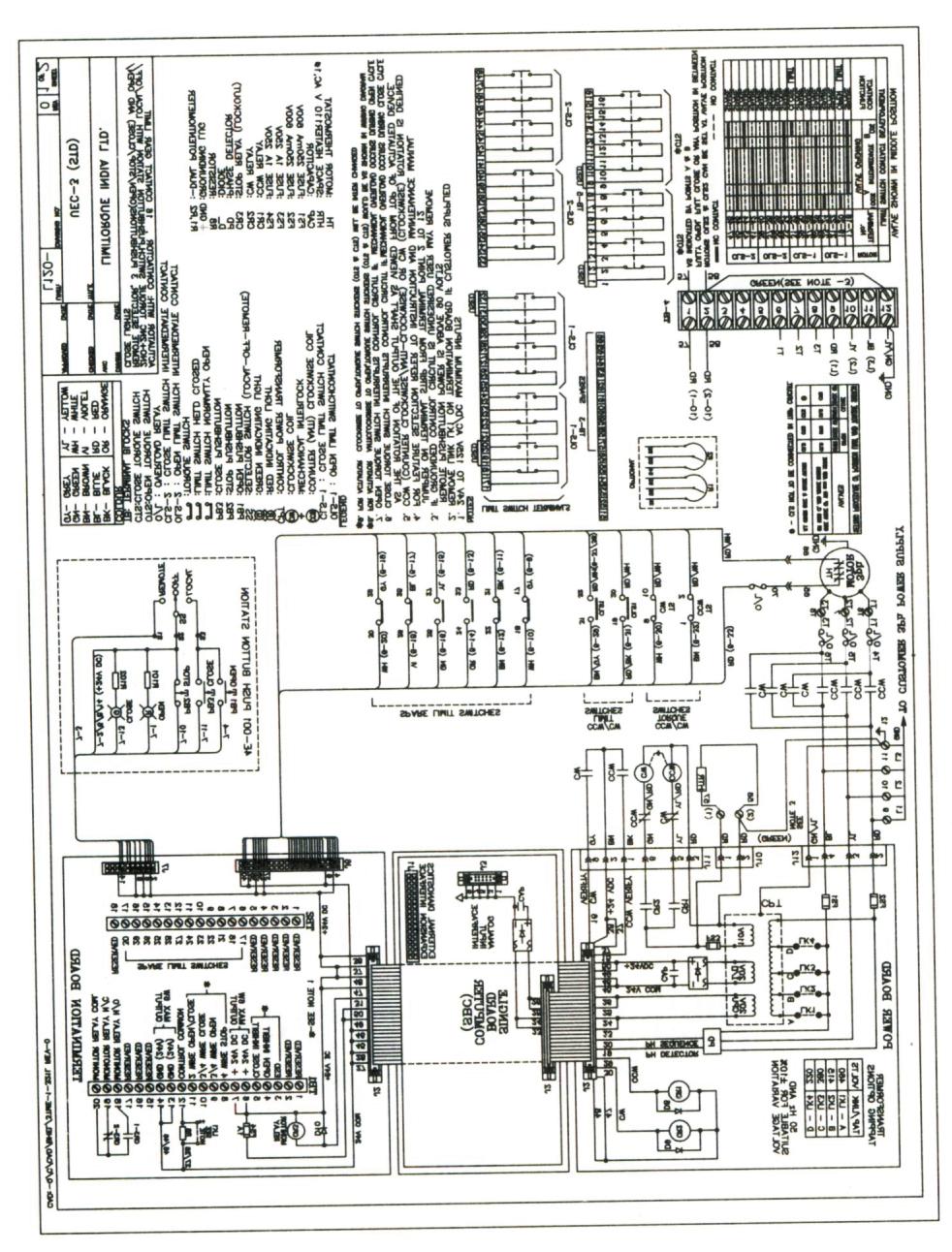
12 ELECTRICAL START - UP 6. Check output rotation - if phase rotation is correct, the valve should begin to open. If valve begins to close-stop. Check that the actuator has been correctly lubricated. immediately. Incorrect phase rotation will lead to serious This is particularly important if the actuator has been in damage if the valve seats. long-term storage. 7. Correct the phase rotation by switching any two of the 2. Ensure that the geared limit switch has been correctly set three power leads for three-phase power. per instructions in this manual. (see Geared Limit Switch 8. The actuator should now operate correctly and will be Section). stopped at the end of travel positions by torque or limit 3. It the valve stem (Rising stem applications) is not visible, switch functions. (Premature stopping may be caused by remove the stem cover or handwheel cover plate so that incorrect limit switch of torque switch settings or line stem will not damage the hand wheel adaptor housing obstructions in the valve). Replace stem cover or cover (PC No. 27) Page No.-6. plate. 4. Engage manual operation and hand crank valve well away from end of travel positions. 5. Turn on power supply and operate the actuator. TYPICAL WIRING DIAGRAM The wiring diagram below is a representation of a typical application and may not be applicable to your specific actuator. Please refer to the wiring diagram supplied with your unit to confirm the actual equipment supplied.
13 2
14 3
15 OPTIONAL SIDE MOUNTED HAND WHEEL NOT APPLICABLE 4
16 BHARAT LIMITORQUE LIMITORQUE INDIA LTD. WORKS & MARKETING OFFICE Plot No. 48, Sector-24, Faridabad Phone: , Fax: sales@limitorqueindia.com, limitorque@vsnl.com, Website : Q QUALITY ASSURED COMPANY ISO 900:2008 BRANCH SALES OFFICES: CHENNAI DELHI: MUMBAI KOLKATA PUNE 65, Broadway, 3rd Floor, Chennai , Phone: , Fax: , libacom@vsnl.com E-45/2, Phase-II, Okhla Industrial Area, New Delhi , Phone : , , Fax: , Neelam, 08, Dr. R. G. Thadani Marg, Off Worli Seaface Road, Worli, Mumbai , Phone: , Fax : , bso@limitorqueindia.com, libabom@vsnl.net Chatterjee International Centre, Suit No. 6, 7th Floor, 33-A, Chowrihnghee Road, Kolkata Phone: , , Fax: kso@limitorqueindia.com, limitorque@sify.com, limitorque2008@gmail.com /03, Gera Garden, Koregaon park road, Pune-400, Tele Fax , pune@limitorqueindia.ocm TM Bharat Limitorque
USER INSTRUCTIONS. Limitorque L through L Installation Operation Maintenance. Experience In Motion FCD LMENIM A4 05/15
 USER INSTRUCTIONS Limitorque L20-90 through L20-2000 FCD LMENIM203-0-A4 05/5 Installation Operation Maintenance Experience In Motion 2 Limitorque L20-90 through L20-2000 FCD LMENIM203-0-A4 05/5 Contents
USER INSTRUCTIONS. Limitorque L Actuator. Installation Operation Maintenance. Experience In Motion FCD LMENIM A4 06/15
 USER INSTRUCTIONS Limitorque L0-85 Actuator FCD LMENIM0-03-A4 06/5 Installation Operation Maintenance Experience In Motion Contents Introduction 4. Purpose 4. User Safety 4 Initial Inspection and Storage
USER INSTRUCTIONS. Installation Operation Maintenance. Limitorque Actuation Systems L120 Series. Experience In Motion. For L through L120-40
 USER INSTRUCTIONS Limitorque Actuation Systems L120 Series For L120-10 through L120-40 FCD LMENIM1201-01 07/06 Installation Operation Maintenance Experience In Motion Contents 1 Introduction 4 1.1 Purpose
Operation & Instructions Manual SA 3 - SA 100 SAR 3 - SAR 100
 Operation & Instructions Manual SA 3 - SA 100 SAR 3 - SAR 100 Warnings and notes Failure to observe the warnings and notes may lead to serious injuries or damage. Qualified personnel must be thoroughly
USER INSTRUCTIONS. Limitorque SMB Series/SB Series. Installation Operation Maintenance. Experience In Motion FCD LMENIM AQ 6/15
 USER INSTRUCTIONS Limitorque SMB Series/SB Series FCD LMENIM1401-05-AQ 6/15 Installation Operation Maintenance Experience In Motion Contents 2 1 Introduction 6 1.1 Purpose 6 1.2 User Safety 6 2 Initial
USER INSTRUCTIONS. Limitorque SMB Series/SB Series. Installation Operation Maintenance. Experience In Motion FCD LMENIM /13
 USER INSTRUCTIONS Limitorque SMB Series/SB Series FCD LMENIM1401-02 11/13 Installation Operation Maintenance Experience In Motion Contents 2 1 Introduction 6 2 Product Capabilities and Features 7 3 Actuator
Valtek Auxiliary Handwheels and Limit Stops
 Valtek Auxiliary s and Limit Stops Table of Contents Page 1 General information 2 Installation 2 Side-mounted handwheels, size 25 and 50 (linear actuators) 3 Side-mounted handwheels, size 100 and 200 (linear
USER INSTRUCTIONS. Limitorque HBC Series. Installation Operation Maintenance. Experience In Motion FCD LMENIM A4 (10/14)
") USER INSTRUCTIONS Limitorque HBC Series FCD LMENIM3501-02-A4 (10/14) Installation Operation Maintenance Experience In Motion Contents 1 Introduction 3 1.1 Purpose 3 1.2 User Safety 3 2 Inspection, Installation,
USER INSTRUCTIONS Limitorque HBC Series FCD LMENIM3501-02-A4 (10/14) Installation Operation Maintenance Experience In Motion Contents 1 Introduction 3 1.1 Purpose 3 1.2 User Safety 3 2 Inspection, Installation,
Hopkinsons Fig 9052 VALVE ACTUATOR
 Excellent Power & Industrial Solutions Standard Operating & Maintenance Instructions Hopkinsons Fig 9052 VALVE ACTUATOR CUT-AWAY OF FIG. 9052 GEAR BOX, WITH LIMIT SWITCH & VALVE POSITION INDICATOR HOP
Hopkinsons Fig 9051 VALVE ACTUATOR
 Excellent Power & Industrial Solutions Standard Operating & Maintenance Instructions Hopkinsons Fig 9051 VALVE ACTUATOR TERMINAL BOX TERMINAL BOX COVER SPINDLE COVER SEAL BEARING HOUSING MOTOR TAPERED
USER INSTRUCTIONS. Limitorque LY Series: LY 1001, LY 2001 and LY Installation Operation Maintenance. Experience In Motion
 USER INSTRUCTIONS Limitorque LY Series: LY 1001, LY 001 and LY 3001 FCD LMENIM1501-00 11/11 Installation Operation Maintenance 0 50 100 L i m i t o r q u e Experience In Motion Limitorque LY Series: LY
ANDCO Eagle Actuator Instruction Manual
 ANDCO Actuators ANDCO Eagle Actuator Instruction Manual The information contained in this manual is essential to safe, successful, long term operation of your Andco Eagle Linear Actuator. Read and follow
Fisher 657 Diaphragm Actuator Sizes and 87
 Instruction Manual 657 Actuator (30-70 and 87) Fisher 657 Diaphragm Actuator Sizes 30 70 and 87 Contents Introduction... 1 Scope of Manual... 1 Description... 2 Specifications... 2 Installation... 3 Mounting
VA-908x Series Electric Rotary Actuators for Two-Position and Modulating Service
 VA-908x Series Electric Rotary Actuators for Two-Position and Modulating Service Installation Instructions VA-908x Code No. LIT-12011566 Issued August 24, 2009 Applications The VA-908x Series Electric
INSTRUCTION MANUAL ACTUATOR CLASSE I TYPE MA, MB
 ACTUATOR CLASSE I TYPE MA, MB CONTENTS Page : 2/13 PRODUCT DESCRIPTION General description 3 Product specification 5 INSTALLATION Storage 6 Unpacking 7 Handling 7 Installation : Mechanical 7 Installation
USER INSTRUCTIONS. Limitorque TM V Series. Installation Operation Maintenance. Experience In Motion FCD LMENIM AQ 02/15
 USER INSTRUCTIONS Limitorque TM V Series FCD LMENIM3601-01-AQ 02/15 Installation Operation Maintenance Experience In Motion Contents 1 Introduction 4 1.1 Purpose 4 1.2 User Safety 4 2 Inspection, Installation
Hopkinsons Fig 9151 Issue pre 1980 VALVE ACTUATOR
 Excellent Power & Industrial Solutions Standard Operating & Maintenance Instructions Hopkinsons Fig 9151 Issue pre 1980 VALVE ACTUATOR CUT AWAY OF FIG 9151 VALVE ACTUATOR HOP 9151 / Issue Pre 1980/Jan
Limitorque Actuation Systems Rev. A May Limitorque WTR Series Installation and Maintenance for WTR-3 through WTR-575
 330-15000 Rev. A May 2003 Limitorque WTR Series Installation and Maintenance for WTR-3 through WTR-575 330-15000 Rev. A May 2003 Limitorque WTR Series Installation and Maintenance for WTR-3 through WTR-575
Manual E1195 (MCP) Series 2000
 Series 2000") When communicating with EIM for replacement parts or for technical questions, we MUST have actuator nameplate information, including Job, Serial, and Model numbers. This allows us to check records of EIM
When communicating with EIM for replacement parts or for technical questions, we MUST have actuator nameplate information, including Job, Serial, and Model numbers. This allows us to check records of EIM
Installation, Operation and Maintenance Manual
 HQ 005. ELECTRIC ACTUATORS QUARTER-TURN ELECTRIC ACTUATORS Installation, Operation and Maintenance Manual s Version Ver. 1 Revision Rev. 1 Document No. HKQI-611 Small & Compact Design High corrosion resistance
Disassembly and Reassembly for WG Series Worm Gear Operator. User Instructions Part Number: XXXXXX, Rev. 0 Release: February 2017
 Disassembly and Reassembly for WG Series Worm Gear Operator User Instructions Part Number: XXXXXX, Rev. 0 Release: February 2017 User Instructions Doc. Number: XXXXXXXX Table of Contents February 2017,
DRAFT. Installation, Operation and Maintenance Instructions for Emerson KBG-V Series
 Part Number: KBG-V.IOM.1001, Rev. 0 Release: February 2017 Installation, Operation and Maintenance Instructions for Emerson KBG-V Series DRAFT Part Number: KBG-V.IOM.1001, Rev. 0 Table of Contents February
NOAH ACTUATOR NA-SERIES MANUAL EMICO EUNHA MACHINERY INDUSTRIAL CO.,LTD.
 NOAH ACTUATOR NA-SERIES MANUAL EMICO EUNHA MACHINERY INDUSTRIAL CO.,LTD N A Table of Contents 1. Caution 2 2. Storage 4 3. Actuator Specification 5 4. Standard Specification 7 5. Optional Specification
Fig.01 Fig.02 Fig.03. Disassembly & Reassembly Instructions SBV-HP - Page 3
 M12A14 WITH FLOATING BACKSEAT 3 Fig.01 Fig.02 Fig.03 Disassembly & Reassembly Instructions SBV-HP - Page 3 M12A14 WITH FLOATING BACKSEAT 3 1. Caution, before any attempt is made to disassemble, verify
ROM Series. Established Leaders in Flow Control. Installation Manual. Valve Actuators
 ROM Series Installation Manual Valve Actuators Established Leaders in Flow Control Contents Section Page Health and Safety 3 Storage 4 Mounting the actuator 4 Setting the actuator stop bolts 5 Cable connections
Fisher 2052 Diaphragm Rotary Actuator
 Instruction Manual 2052 Actuator Fisher 2052 Diaphragm Rotary Actuator Contents Introduction... 1 Scope of Manual... 1 Description... 1 Specifications... 4 Installation... 4 Actuator Mounting and Changing
MODEL:D-1000X D-1000XLD D-1000Y D-1000YLD D-1000Z
 INSTALLATION & OPERATION MANUAL MODEL:D-1000X D-1000XLD D-1000Y D-1000YLD D-1000Z INDEX WARNINGS BEFORE INSTALLATION INSTALLATION OPERATION MAINTENANCE TROUBLE SHOOTING OUTSIDE DIMENSIONS ACCESSORIES &
Maintenance Information
 80234313 Edition 2 May 2014 Air Grinder, Die Grinder, Sander and Belt Sander Series G1 (Angle) Maintenance Information Save These Instructions Product Safety Information WARNING Failure to observe the
Transfer Valve Actuator Overhaul Instructions
 Rotary Style Transfer Valve Actuators Overhaul Instructions Form No. F-1031 Section 2315 Issue Date 12/10/99 Rev. Date 11/02/11 Table of Contents Introduction.................................. 1 Safety
Andco Series 7000 Actuator Posi-Tork * Acme Screw Instruction Manual
 GE Oil & Gas Andco Series 7000 Actuator Posi-Tork * Acme Screw Instruction Manual Table of Contents Introduction Introduction and General Information... 2 Storage equirements... 2 Installation Installation
Safe & Secure Series Electric Actuator with Internal Battery Back-up Installation, Operation & Maintenance Manual
 Safe & Secure Series Electric Actuator with Internal Battery Back-up Installation, Operation & Maintenance Manual For Use with: SNS4, SNS6, SNS10 & SNS15 Models Additional supplements may be needed for
OVERLOAD CLUTCHES FOR INDEX DRIVES
 The Driving Force in Automation OVERLOAD CLUTCHES FOR INDEX DRIVES WARNING WARNING This is a controlled document. It is your responsibility to deliver this information to the end user of the CAMCO indexer.
VG7000 Valve Linkage for M100 Series Motor Actuators
 Valve and Actuator Manual 977 Actuators and Positioners Section Technical Bulletin VG7000 Series Issue Date 1295 VG7000 Valve Linkage for M100 Series Motor Actuators lntroduction 3 Application Details
Mounting and operating instructions EB 5801 EN. Electric Actuators Type 5801 (Rotary Actuator) Type 5802 (Linear Actuator)
 Type 5802 (Linear Actuator)") Electric Actuators Type 5801 (Rotary Actuator) Type 5802 (Linear Actuator) Linear Actuator with Type 3260 Control Valve Rotary actuator with lever system Linear actuator with Type 3321 (V2001) Control
Electric Actuators Type 5801 (Rotary Actuator) Type 5802 (Linear Actuator) Linear Actuator with Type 3260 Control Valve Rotary actuator with lever system Linear actuator with Type 3321 (V2001) Control
OPERATING INSTRUCTIONS AND SERVICE MANUAL
 OPERATING INSTRUCTIONS AND SERVICE MANUAL 55NAL--270-4 55NL--724-4 55RNL-2-LS-4- COMPLETE TOOL MODEL NO. CODE NO. 55NAL--270-4 20270 55NL--724-4 220724 READ SAFETY RECOMMENDATIONS 55RNL-2-LS-4-24089 BEFORE
Maintenance Information
 04581245 Edition 2 May 2014 Air Grinder, Die Grinder and Sander Series G2 (Angle) Maintenance Information Save These Instructions Product Safety Information WARNING Failure to observe the following warnings,
DRIVE AXLE Volvo 960 DESCRIPTION & OPERATION AXLE IDENTIFICATION DRIVE AXLES Volvo Differentials & Axle Shafts
 DRIVE AXLE 1994 Volvo 960 1994 DRIVE AXLES Volvo Differentials & Axle Shafts 960 DESCRIPTION & OPERATION All 960 station wagon models use type 1041 rear axle assembly. All 960 4-door models use type 1045
ROM Series. Keeping the World Flowing. Installation Manual. Valve Actuators
 ROM Series Installation Manual Valve Actuators Keeping the World Flowing Contents Section Page Health and safety 3 Storage 4 Mounting the actuator 4 Setting the actuator stop bolts 5 Cable connections
Maintenance Information
 80234313 Edition 1 June 2006 Air Grinder, Die Grinder, Sander and Belt Sander Series G1 (Angle) Maintenance Information Save These Instructions WARNING Always wear eye protection when operating or performing
USER INSTRUCTIONS. Limitorque PT Series. Installation Operation Maintenance. Experience In Motion FCD LMENM /10
 USER INSTRUCTIONS Limitorque PT Series FCD LMENM2001-00 01/10 Installation Operation Maintenance Experience In Motion Contents 1 Introduction 1.1 Purpose 4 1.2 User Safety 4 2 Inspection, Installation,
BOLT-ON AND WELD-ON FLUSH FLOOR SLIDEOUT SYSTEMS OPERATION AND SERVICE MANUAL
 BOLT-ON AND WELD-ON FLUSH FLOOR SLIDEOUT SYSTEMS OPERATION AND SERVICE MANUAL TABLE OF CONTENTS SYSTEM...... Warning........ Description...... Prior to Operation OPERATION... Main Components... Mechanical...
Kysor On/Off Rear Air Fan Drive
 . Proper precautions must be taken to prevent personal injury from contact with moving parts, unintended engine start, or other hazards present when working with powered equipment. Refer to the vehicle
F O R M. Torq/Gard Installation, Operation and Maintenance Instructions. 8322E Revised March 2016 CAUTION WARNING
 Torq/Gard Installation, Operation and Maintenance Instructions Power Transmission Solutions Regal Beloit America, Inc. 7120 New Buffington Road Florence, KY 41042 Application Engineering: 800 626 2093
ONYX VALVE CO MODEL CER with JORDAN ACTUATOR Installation & Maintenance
 ONYX VALVE CO MODEL CER with JORDAN ACTUATOR Installation & Maintenance OPERATION: (7-2011) The Onyx series CER is electric operated pinch valve, with full round configuration and a single pinching mechanism.
Maintenance Information
 16575128 Edition 2 May 2014 Air Grinder, Sander or Polisher 77A Series Maintenance Information Save These Instructions Product Safety Information Failure to observe the following warnings, and to avoid
Q Range electric direct-drive quarter turn valve actuators. Instruction manual
 Contents Q Range electric direct-drive quarter turn valve actuators Instruction manual Publication number E670E Date of issue 01/07 page 1 Identifying Actuator Parts 2 1.1 Weights 2 2 Mounting Actuator
Maintenance Information
 16573370 Edition 2 February 2014 Air Grinder 99V Series Maintenance Information Save These Instructions Product Safety Information WARNING Failure to observe the following warnings, and to avoid these
MODELS 3100,3130,3160, 1300, 1330,1360 EXHAUST SYSTEM
 MODELS 3100,3130,3160, 1300, 1330,1360 EXHAUST SYSTEM WALBRO CARBURETOR "WA" SERIES MUFFLER REMOVAL CARBURETOR REMOVAL The muffler assembly should beremoved periodically to inspect for excessive carbon
Series 100 Slam Shut Valve
 IMP 8775 Series 00 Slam Shut Valve Sizes ", ", 4" Installation & Maintenance Instructions Read carefully and follow all instructions shipped with this regulator. The incorrect installation of this equipment
OPERATION INSTRUCTONS MODEL SG 05.1 SG Quarter-Turn Actuators
 OPERATION INSTRUCTONS MODEL SG 05.1 SG 12.1 Quarter-Turn Actuators AUMA Actuators, Inc. USA 100 Southpointe Boulevard Canonsburg, PA 15317 724-743-2862 Fax: 724-743-4711 www.auma-usa.com email: mailbox@auma-usa.com
Installation and Service Instructions for Self Adjust Brakes 81,000 Series
 Spring-Set Disc Brakes P/N -07-9-00 effective 07/0/0 Installation and Service Instructions for Self Adjust Brakes,000 Series Current revision available @ www.stearns.rexnord.com Tools required for installation
The chronograph calibres CHRO PC 17 jewels CHRO C12 PC 17 jewels CHRO C12 PC AMPM GMT 17 jewels CHRO PC CAL 17 jewels
 Technical guide The chronograph calibres 860 27 CHRO PC 17 jewels 861 27 CHRO C12 PC 17 jewels 910 27 CHRO C12 PC AMPM GMT 17 jewels 930 27 CHRO PC CAL 17 jewels o 27.00 mm / Power-reserve Jewel number
STEERING SYSTEM 6 A POWER STEERING
 STEERING SYSTEM 6 A 22147 POWER STEERING Table of Contents Page Specifications............................ 6A-1 Torque Specification................... 6A-1 Special Tools............................ 6A-1
Sofa Slideout Assembly OWNER'S MANUAL. Rev: Page 1 Sofa Slideout Owners Manual
 Sofa Slideout Assembly OWNER'S MANUAL Rev: 06.14.2016 Page 1 Sofa Slideout Owners Manual TABLE OF CONTENTS Warning, Safety, and System Requirement Information 3 Product Information 3 Prior to Operation
Hydraulic Rotary Hammer Drill
 M a s c h i n e n f a b r i k G m b H Hydraulic Rotary Hammer Drill Type 2 2406 0010 Techn. Doc. No. 262 Illustration can differ from the original Repair Manual and Spare Parts List 224060010_Inst_en_Version_06.doc
ONYX VALVE CO MODEL CAR, CAP-PFO Installation & Maintenance
 ONYX VALVE CO MODEL CAR, CAP-PFO Installation & Maintenance OPERATION: (4-2010) The Onyx series CAR-PFO and CAP-PFO pinch valves fail open on loss of air. The simple spring and air bag arrangement drives
DeZURIK R1 AND R2 POWERRAC ACTUATORS
 R1 AND R2 POWERRAC ACTUATORS Instruction D10268 July 2016 Instructions These instructions provide installation, operation, and maintenance information for R1 AND R2 POWERRAC Actuators. They include procedures
radial GATES Waterman Industries of Egypt
 radial GATES USES Maintenance of water elevations in canals Increased storage capacity for reservoirs Diversion of water for irrigation Flow control preserving wide, clear waterways Other areas requiring
Pneumatic Angle Grinder also for Underwater Use Type
 M a s c h i n e n f a b r i k G m b H Pneumatic Angle Grinder also for Underwater Use Type 1 4311 0050 Illustration can differ from the original Repair Manual and Spare Parts List Compiled: 22.06.11 143110050_Inst_en_Version_00
Installation Instructions
 WE-500 Series Electric Actuator Installation Instructions Introduction The WE-500 Series electric actuator is a rotary valve actuator with outputs of 500 in-lbs. It has been designed for NEMA 4, 4X and
Kysor On/Off Rear Air Fan Drive
 . Proper precautions must be taken to prevent personal injury from contact with moving parts, unintended engine start or other hazards present when working with powered equipment. Refer to the vehicle
Standard Valves Series Globe Valves Series Angle Valves Series Way-Valves
 Installation, Operation, Maintenance Instructions Standard Valves Series 035 000 Globe Valves Series 031 000 Angle Valves Series 033 000 3-Way-Valves 1 GENERAL INFORMATION These instructions are designed
Fisher 1061 Pneumatic Piston Rotary Actuator with Style H & J Mounting Adaptations
 Instruction Manual 1061 H & J Actuator Fisher 1061 Pneumatic Piston Rotary Actuator with Style H & J Mounting Adaptations Contents Introduction... 1 Scope of Manual... 1 Description... 2 Specifications...
Installation, Operating & Maintenance Instructions
 Electromechanical Linear Actuators Installation, Operating & Maintenance Instructions with parts list TAC Models with Clutch TAL Models with Limit Switches TAC Models with Limit Switches and Potentiometer
ELECTRIC BEDROOM SLIDEOUT SYSTEM OPERATION AND SERVICE MANUAL
 ELECTRIC BEDROOM SLIDEOUT SYSTEM OPERATION AND SERVICE MANUAL TABLE OF CONTENTS SYSTEM...... Warning...... Description..... Prior to Operation... System Maintenance..... OPERATION... Warning... Extending
Hopkinsons Fig 9050M & 9151M Issue 1982 ELECTRIC ACTUATOR Modulating Duty
 Excellent Engineering Solutions Standard Operating & Maintenance Instructions Hopkinsons Fig 9050M & 9151M Issue 1982 ELECTRIC ACTUATOR Modulating Duty SECTIONAL ARRANGEMENT OF FIG. 9050M & 9151M ACTUATOR
OPERATION AND MAINTENANCE MANUAL
 WREN IBT SERIES HYDRAULIC TORQUE WRENCHES IBT SQUARE DRIVE SERIES OPERATION AND MAINTENANCE MANUAL FOR WREN Products: POINT 75, 1IBT, 3IBT, 5IBT, 8IBT, 10IBT, 20IBT, 25IBT, 35IBT, 50IBT SQUARE DRIVE HYDRAULIC
SD Bendix Manual Slack Adjusters DESCRIPTION ADJUSTING MECHANISM OPERATION
 SD-05-1200 Bendix Manual Slack Adjusters WORM SHAFT (LOCK SCREW) FIGURE 1 - POSITIVE LOCK TYPE SLACK ADJUSTER DESCRIPTION In an s-cam type foundation brake, the final link between the pneumatic system
USER INSTRUCTIONS. Installation Operation Maintenance. NAF Setball SF Ball Sector Valves. Experience In Motion FCD NFENIM A4 09/16
 USER INSTRUCTIONS NAF Setball SF Ball Sector Valves FCD NFENIM4156-00 A4 09/16 Installation Operation Maintenance Experience In Motion Contents SAFETY 3 1 General 3 2 Lifting 4 3 Receiving Inspection 4
36 Tiller Wheel Horse Lawn and Garden Tractor Attachment
 Form No. 9 6 Rev B 6 Tiller Wheel Horse Lawn and Garden Tractor Attachment Model No. 797 890000 and Up Operator s Manual English(En) Contents Page Introduction................................ Safety.....................................
DeZURIK R1 POWERRAC ACTUATOR ON 1/2-3" PEC ECCENTRIC VALVES
 R1 POWERRAC ACTUATOR ON 1/2-3" PEC ECCENTRIC VALVES Instruction D10381 August 2012 Instructions These instructions provide information about the R1 PowerRac actuator. They are for use by personnel who
Tech Note Truck 14 & 15.5 Twin Plate Cast Iron Type Installation Guidelines
 1. (14 & 15.5 ) Check condition of the flywheel. Grind to resurface or replace flywheel. Surface MUST BE machined or premature clutch failure can occur. Flywheel depth must be 2.938 (74.62mm) for 14 (350mm)
INSTALLATION INSTRUCTIONS 88029
 INSTALLATION INSTRUCTIONS 88029 FOR SUSPENSION SYSTEMS RS6503: JEEP WRANGLER (TJ) READ ALL INSTRUCTIONS THOROUGHLY FROM START TO FINISH BEFORE BEGINNING INSTALLATION REV F IMPORTANT NOTES! WARNING: This
Model 2300DL Installation Guide
 Model 2300DL Installation Guide POWER ACCESS CORPORATION 4 HERSHEY DRIVE, DOCK 4 ANSONIA, CT 06401 800-344-0088 WEBSITE: www.power-access.com EMAIL: salesinfo@power-access.com 1 STANDARD PARTS MODEL 2300DL
Installation, Service and Parts List Series 56,800 for Class I & II, Division 2 Manual Adjust Brakes
 Spring-Set Disc Brakes P/N 8-078-905-8 effective /0/0 Installation, Service and Parts List Series 56,800 for Class I & II, Division Manual Adjust Brakes Tools required for installation and servicing: /8
Fisher 1052 Size 70 Diaphragm Rotary Actuator
 Instruction Manual 1052 Size 70 Actuators Fisher 1052 Size 70 Diaphragm Rotary Actuator Contents Introduction... 1 Scope of Manual... 1 Description... 3 Specifications... 3 Educational Services... 3 Installation...
Type 657 Diaphragm Actuator Sizes and 87
 Instruction Manual Form 1900 January 2000 Type 657-70 & 87 Type 657 Diaphragm Actuator Sizes 30-70 and 87 Contents Introduction............................... 1 Scope of Manual.............................
Kysor Rear Air Fan Drives
 On/Off Technology for Heavy-Duty Truck Applications Installation & Service Guide Kysor Rear Air Fan Drives thermal.borgwarner.com For Additional BorgWarner Thermal Systems Information: 800-927-7811 USA
Electronic Proportional (EP) Control for Heavy Duty Series 0/1 Piston Pumps Model 33 Model 39 Model 46. Model 54 Model 64 Model 76
 Control for Heavy Duty Series 0/1 Piston Pumps Model 33 Model 39 Model 46. Model 54 Model 64 Model 76") Electronic Proportional (EP) Control for Heavy Duty Series 0/1 Piston Pumps Model 33 Model 39 Model 46 Model 54 Model 64 Model 76 Table of Contents Introduction.......................................................
Electronic Proportional (EP) Control for Heavy Duty Series 0/1 Piston Pumps Model 33 Model 39 Model 46 Model 54 Model 64 Model 76 Table of Contents Introduction.......................................................
ROLLER GATES. Waterman Industries of Egypt. Roller gates are nominated for heavy duty service where large loads and sizes are going to be encountered.
 ROLLER GATES Roller Gates are ideally suited for controlling water in any large openings such as may be found in power plants, water and sewage treatment facilities, flood control projects, irrigation
Quarter Master Series 94 Actuator
 Quarter Master Series 94 Actuator Installation, Operation and Maintenance Manual Assembly Series 94 Manual Rev V 9/5/13 Page 1 of 12 Table of Contents Series 94 Electric Actuator Introduction... 3 Description...
OLYMPIAN MODEL 740 Operation and Service Manual
 OLYMPIAN MODEL 740 Operation and Service Manual P/N 133911-102 FCI MANUAL P/N 133865-001 Data herein has been verified and validated and believed adequate for the intended use. If the machine or procedures
Y20EBA Linkage Kit, M100 to Barber-Colman 1/2 to 1-1/4 Inch Valves
 Installation Sheets Manual 121 Also in FANs 977, 628.1 Technical Bulletin Issue Date 0893 Y20EBA Linkage Kit, M100 to Barber-Colman 1/2 to 1-1/4 Inch Valves lntroduction 2 Application Details *2 Glossary
Self-Adjust Clutch Installation Guide
 Self-Adjust Clutch Installation Guide 0 STOP! READ CAREFULLY BEFORE INSTALLING CLUTCH This clutch must be installed by a qualified installer. Improper installation or failure to replace or resurface the
DeZURIK DR 125 ROTARY DIAPHRAGM ACTUATOR
 DR 125 ROTARY DIAPHRAGM ACTUATOR Instruction D10507 January 2017 Instructions These instructions provide information about. They are for use by personnel who are responsible for installation, operation
Maintenance Information
 16572679 Edition 2 May 2014 Air Drill QP Series Maintenance Information Save These Instructions Product Safety Information WARNING Failure to observe the following warnings, and to avoid these potentially
Wheel Horse. 44 Snowthrower. for 5xi Lawn and Garden Tractors. Model No & Up. Operator s Manual
 FORM NO. 8 Rev A Wheel Horse Snowthrower for 5xi Lawn and Garden Tractors Model No. 7966 890050 & Up Operator s Manual IMPORTANT: Read this manual, and your tractor manual, carefully. They contain information
DeZURIK DR 40B ROTARY DIAPHRAGM ACTUATOR
 DR 40B ROTARY DIAPHRAGM ACTUATOR Instruction D10506 October 2016 Instructions These instructions provide information about s. They are for use by personnel who are responsible for installation, operation
Instruction Manual & Parts List For H/G323FXFSX-500_ & 800_ Pumps With Flowserve Type BX Cartridge Seal
 TM Instruction Manual & Parts List For H/G323FXFSX-500_ & 800_ Pumps With Flowserve Type BX Cartridge Seal WARNING This Special Instruction Manual and General Instructions Manual, CA-1, should be read
1. Remove the crankshaft pulley, engine coolant pump pulley and drive belt. 2. Remove the timing belt cover.
 DISASSEMBLY 1. Remove the crankshaft pulley, engine coolant pump pulley and drive belt. 2. Remove the timing belt cover. 3. Turn the crankshaft clockwise and align the timing marks so as to bring the No.
Installation, Operation and Maintenance Manual DOC.IOM.MO.E October MO-Series Manual Override Gearboxes
 Installation, Operation and Maintenance Manual DOC.IOM.MO.E October 2017 MO-Series Manual Override Gearboxes EL Matic TM Installation, Operation and Maintenance Manual Table of Contents DOC.IOM.MO.E Rev.
walton TEMPERATURE CONTROL SYSTEMS Pneumatically Operated (Rotary)
") walton TEMPERATURE CONTROL SYSTEMS Pneumatically Operated (Rotary) WALTON ENGINEERING CO. LTD. 61 London Road St Albans Hertfordshire AL1 1LJ England Telephone +44 (0)1727 855616 Fax +44 (0)1727 841145
walton TEMPERATURE CONTROL SYSTEMS Pneumatically Operated (Rotary) WALTON ENGINEERING CO. LTD. 61 London Road St Albans Hertfordshire AL1 1LJ England Telephone +44 (0)1727 855616 Fax +44 (0)1727 841145
CLUTCH CONTENTS SERVICE DIAGNOSIS. (a) Worn or damaged disc assembly. (b) Grease or oil on disc facings. (c) Improperly adjusted cover assembly.
 Worn or damaged disc assembly. (b) Grease or oil on disc facings. (c) Improperly adjusted cover assembly.") CLUTCH CONTENTS -GROUP 6 Page CLUTCH HOUSING ALIGNMENT... 6 CLUTCH PEDAL FREE PLAY 1 CLUTCH RELEASE BEARING 5 CLUTCH RELEASE FORK... 5 CLUTCH SERVICING 2 PILOT BUSHING CRANKSHAFT TO TRANSMISSION DRIVE
CLUTCH CONTENTS -GROUP 6 Page CLUTCH HOUSING ALIGNMENT... 6 CLUTCH PEDAL FREE PLAY 1 CLUTCH RELEASE BEARING 5 CLUTCH RELEASE FORK... 5 CLUTCH SERVICING 2 PILOT BUSHING CRANKSHAFT TO TRANSMISSION DRIVE
V5422L / V5422E ACTUATED BUTTERFLY VALVES. FEATURES With factory-mounted electric actuator
 V5422L / V5422E ACTUATED BUTTERFLY VALVES FEATURES With factory-mounted electric actuator SPECIFICATION DATA Centric butterfly valve with elastomer liner Wide DN range (DN250 through DN600) For heating
AE Installation Operation & Maintenance Instructions
 AE-1400 Installation Operation & Maintenance Instructions IMPORTANT Please read the installation operation and maintenance instruction prior to using any Jomar Valve component. Failure to follow the instructions
Emerson Power Transmission P.O. Box 687 Maysville, KY Phone:
 Torq/Gard Installation, Operation and Maintenance Instructions Emerson Power Transmission P.O. Box 687 Maysville, KY 41056 Phone: 606-564-2093 www.emerson-ept.com FORM 8322 Revised June 2007 Installation
Removal and Installation of Fuel Injection Pumps
 Page 16 of 126 worn considerably. Fig. C shows how the flat end of a new plunger makes poor contact with a worn lifter, resulting in rapid wear to both parts. An injection pump can have a good fuel flow
Installation and Operation EL Series Electric Actuator
 Installation and Operation EL Series Electric Actuator VALVE AUTOMATION SYSTEMS 5.4 El 02.99 El-O-matic Electric Actuators... El-o-matic electric actuators are the most advanced actuators of their type
V-7 Valves. Installation and Parts INSTALLATION: M400-10: V2: 03/17. An IDEX Energy & Fuels Business. V7 Valves IOM and Parts
 V-7 Valves Installation and Parts L I Q UID C O N T R O L S An IDEX Energy & Fuels Business V7 Valves IOM and Parts INSTALLATION: M400-10: V2: 03/17 WWW.LCMETER.COM 1 TABLE OF CONTENTS Description...Page
Model DFR 070/156/220 Rotary Actuator
 Figure 1 DFR 156 TABLE OF CONTENTS General 2 Actuator Assembly 18 Scope 2 Bushing / Yoke Assembly 18 Principles of Operation 2 Spring Barrel Assembly 18 Safety Caution 2 Diaphragm Plate Assembly 20 Specifications