|
|
|
- Leonard Taylor
- 5 years ago
- Views:
Transcription
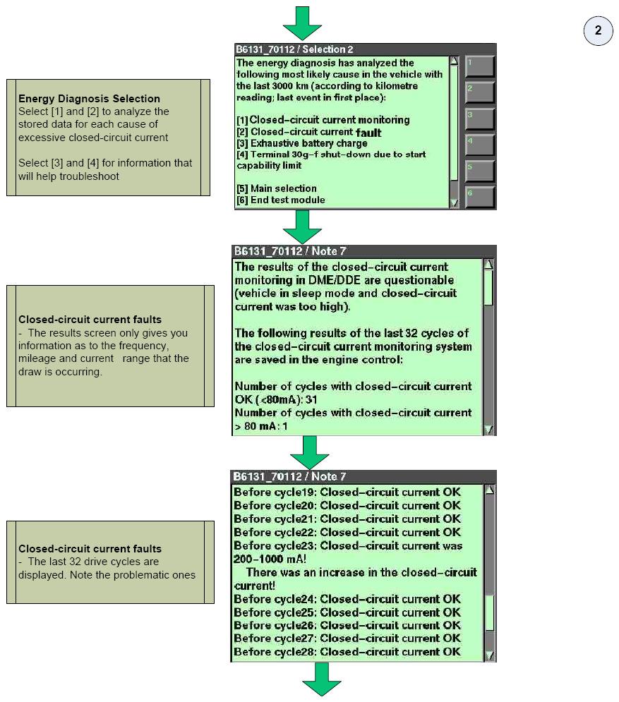
1 Page 1 of BMW 535i 3.0L Eng CLOSED-CIRCUIT CURRENT MEASUREMENT TECHNICAL SERVICE BULLETIN Reference Number(s): SI B , Date of Issue: November 2015 BMW: All Models GROUP: General Electrical Systems Superceded Bulletin(s): SI B , Date of Issue: January 2014 This Service Information bulletin supersedes SI B dated January SUBJECT Closed-circuit Current Measurement SITUATION Closed circuit current needs to be measured. Excessive closed-circuit currents may occur continuously or intermittently, and may cause the battery to discharge prematurely. CAUSE The increase in closed-circuit current may be caused by a faulty control unit, or by the installation of a non-approved accessory. INFORMATION In a situation where a vehicle has broken down due to a discharged battery, for diagnostic purposes it is important to not disconnect the battery. This is because a control unit will be reset if the battery is disconnected. Following a reset, the faulty control unit may start functioning correctly again, making accurate diagnosis impossible. To correctly measure closed-circuit current, the 50-amp clip-on probe (previously used with the IMIB) or the 100-amp clip-on probe can now be used in conjunction with the IMIB (Integrated Measurement Interface Box) to properly diagnose closed-circuit current problems over an extended period of time. Connect the amp clip-on probe directly to the IMIB Measurement input 3 (green socket). PROCEDURE NOTE: It is very important that any "Power management" faults stored be diagnosed and corrected, and the "Energy Diagnosis" test plan carried out before the following procedure is performed. Only perform this procedure if closed-circuit current violations are listed in the "Most Likely Cause" list.
2 Page 2 of Check and test the battery using the BMW Battery Tester. Refer to SI B for information about the BMW Battery. Refer to SI B for vehicles equipped with advanced onboard battery diagnostics that do not require the BMW Battery Tester. If necessary, recharge or replace the battery. 2. If the battery is installed in the trunk, open the trunk and turn the lock to the locked position, using a screwdriver or similar (simulates the trunk lid being closed). The hood must be closed. If the battery is installed in the engine compartment, open the hood and pull the front lid contact switch fully up, and lock in this position (workshop position, simulates the front lid being closed). The trunk must be closed. 3. With the exception of the trunk/hood above, all other doors/lids must be closed. 4. In order to simulate normal closed-circuit conditions: 1. Turn the ignition on and activate all electrical consumers, including any accessories. Turn the ignition off. In some cases, a drive cycle may need to be carried out in order to duplicate a closed-circuit current problem. 2. Open and close the driver's door (simulates somebody getting out). 3. Lock the car, arming the DWA if this is installed. 5. Measure closed circuit current. In general, closed-circuit current consistently over 50mA must be investigated. Depending on the vehicle's equipment, closed-circuit current by vehicle model is approximately as follows: E31 E32 E34 50 milliamps after 16 minutes 50 milliamps after 16 minutes E36, Z3 30 milliamps after 16 minutes E38 E39 E46 E60, E61, E63, E64 50 milliamps after 16 minutes 40 milliamps after minutes E65, E66 40 milliamps after minutes E53 E70, E71, E72 40 milliamps after minutes with TCU (30 minutes without TCU) E83 E82, E84, E88 40 milliamps after minutes with TCU (30 minutes without TCU) 40 milliamps after minutes with TCU (30 minutes without TCU)
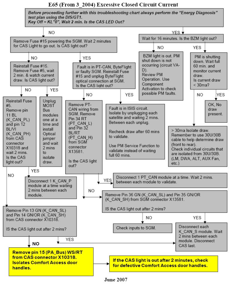
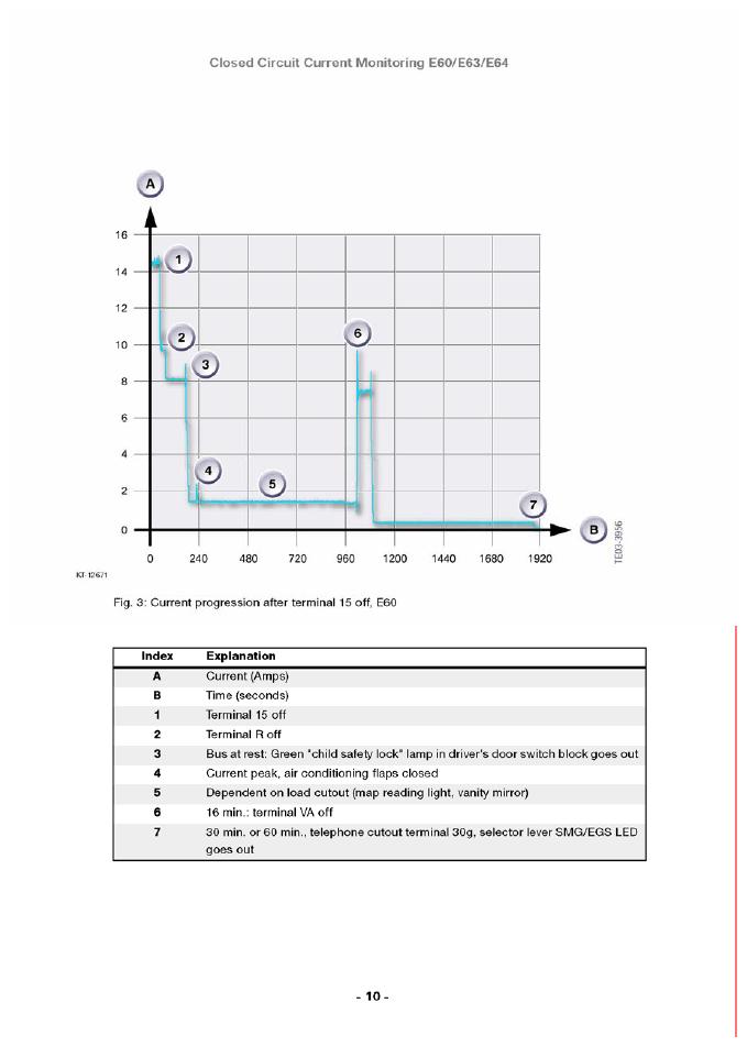
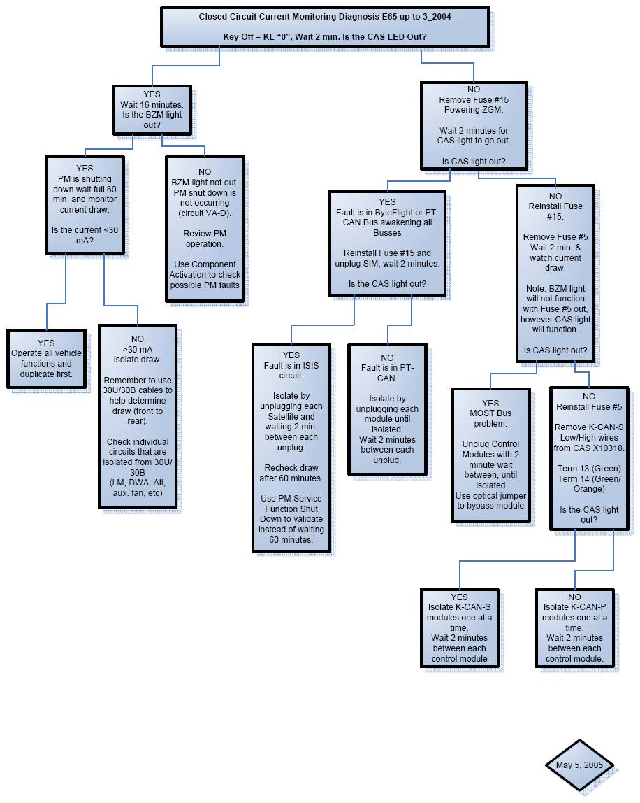
3 Page 3 of 11 E90, E91, E92, E93 E85 E89 E52 All F-Series vehicles G12 40 milliamps after minutes with TCU (30 minutes without TCU) 50 milliamps after 16 minutes 9-22 milliamps after 30 minutes 9-22 milliamps after 8 minutes Refer to ISTA FUB-FB K15 for specific testing procedures 6. If the nominal milliamp reading is not achieved after the appropriate time, refer to the attached troubleshooting charts. NOTE: On 2005 MY vehicles equipped with BMW ASSIST, there are additional current fluctuations as high as 500ma that last for approximately 2 minutes. The fluctuations occur every 15 minutes for up to 14 hours after key off. This is considered normal operation of the TCU, and should not be considered a fault. This also applies to 2005 TCUs that are installed into earlier production vehicles as replacement parts. 1. E60, E63, E64 Closed-Circuit Current Troubleshooting E6x up to 9/05 production 2. E60, E61, E63, E64 Closed-Circuit Troubleshooting E6x from 9/05 production 3. E65, E66 Closed-Circuit Current Troubleshooting up to 3/04 production 4. E65, E66 Closed-Circuit Current Troubleshooting from 3/04 production 5. Normal closed-circuit current values for E65, E70, E60, E61, E63, and E64 CLOSED-CIRCUIT CURRENT MEASUREMENT WITH THE IMIB NOTE: This technique with an IMIB is particularly suitable for extended measurements, and provides a graphical readout of recorded measurements over time. It is recommended for situations where the use of a multimeter provided insufficient information for problem diagnosis. 1. The IMIB can be accessed from any ISID within the workshop. 2. Select "Activities". 3. Select "Measuring devices". 4. Select from the "Level 1" column, "Measuring devices", and then "OK". 5. From the "Connection manager" screen, select the free IMIB and "Set up connection".
4 Page 4 of The "Measures devices" screen opens on the "Multimeter" tab. 7. Select the "Oscilloscope" tab. 8. Highlight the "CH1" tab to activate channel Under channel 1, "Source," scroll with the arrows to select "Clip-on probe 50A" or "Clipon probe 100A." 10. Make sure that the clip-on probe is not connected to the battery cable, and acknowledge the pop-up message with "OK." The calibration of the clip-on probe is very important, and must be as close to 0 as possible. If the clip-on probe cannot be calibrated, it must be replaced in order to ensure a proper measurement. Refer to the Parts Information section of this Service Information bulletin for the latest clip-on probe part number. 11. Change the "A/Div" setting to "1A". 12. Under the "Time" selection box, change the "Time/Div" setting based on the number of measurements needed (5 ms to 200 s). The longer times should be selected when performing the measurement over an extended period. 13. Select "CH 1" under "Cursor" to monitor the actual readings. 14. Select "Record" if performing long term measurements. 15. After performing the measurement, select "Record" again; the display will change to "Compress" and display the recorded data on the 1 screen. PARTS INFORMATION Part Number Description Quantity Clip-on probe 100A 1 WARRANTY INFORMATION Not applicable. ATTACHMENTS B610800_Troubleshooting_E6x_From_9_2005

5 Page 5 of 11


6 Page 6 of 11
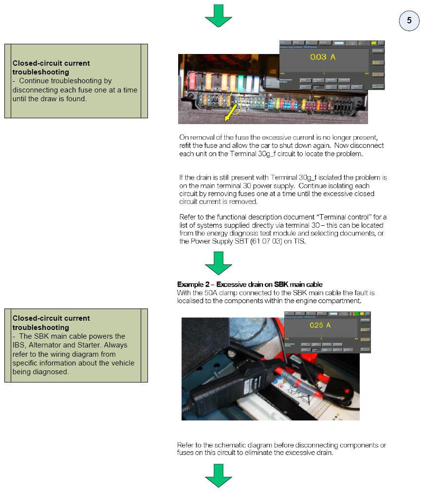
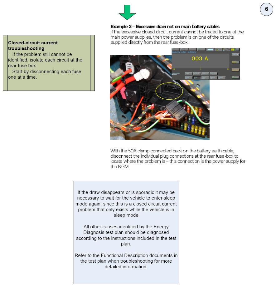
7 Page 7 of 11 B610800_Troubleshooting_E65_From_3_2004

8 Page 8 of 11 B610800_Troubleshooting_E6x_Up_To_9_2005
9 Page 9 of 11 B610800_Troubleshooting_E65_Up_To_3_2004 B610800_Normal_Closed_Circuit_Current_Values
10 Page 10 of 11
11 Page 11 of 11
2006 MINI Cooper S GENINFO Battery - Overview - MINI
 2002-07 GENINFO Battery - Overview - MINI MINI BATTERY MINI BATTERY Purpose of the Automotive Battery The battery is the primary Electromotive Force (EMF) source in the automobile. In addition the battery
2012 Volkswagen Eos Komfort
 Test-ID Specified value min. max. 1 Rich to lean sensor barrier - 0.6241 V voltage 2 Lean to rich sensor barrier - 0.6241 V voltage 7 Minimum voltage at sensor - 0.450 V for test cycle 8 Maximum voltage
CRANKCASE VENTILATION SYSTEM DIAGNOSIS AND MEASUREMENT
 2008 BMW 528i 3.0L Eng CRANKCASE VENTILATION SYSTEM DIAGNOSIS AND MEASUREMENT TECHNICAL SERVICE BULLETIN Reference Number(s): SI B11 03 08, Date of Issue: October, 2013 BMW: All GROUP: Engine Superceded
Service Bulletin. Charging System Testing
 Service Bulletin Model Applicable To File Under Bulletin No. ALL 1986 1992 ELECTRICAL 92-001 Issue Date JAN 31, 1992 Charging System Testing Use the following procedures and specifications in place of
1 of 5 9/19/2017, 8:29 PM
 1 of 5 9/19/2017, 8:29 PM Electrical Emergency Release, Front Cover (Hood) and Trunk Lid - Early Production (Emergency Unlocking of the Luggage Compartment Lids) ALLDATA EDITORS NOTE: This article is a
ElPower script. Contents. ElPower script diagnostics of the engine starting and charging system
 ElPower script Contents 1. Purpose...2 2. Recording the waveforms and starting the script...3 3. Analysis results...5 3.1 The "Report" tab...5 3.2 The "Results of analysis" tab...6 3.3 The "Graphics" tab...9
Service Bulletin. Reason For Bulletin: Diagnosis of a G3 Vision Unit with a problem of Unit would not turn on with ignition.
 KUSTOM SIGNALS, INC. Number: 1738 Date Issued: January 27, 2015 Service Bulletin Product Affected: G3 Vision Reason For Bulletin: Diagnosis of a G3 Vision Unit with a problem of Unit would not turn on
SECTION 12M - SUPPLEMENTAL RESTRAINT SYSTEM (VERSIONS 8.0 AND 8.1)
") SECTION 12M - SUPPLEMENTAL RESTRAINT SYSTEM (VERSIONS 8.0 AND 8.1) IMPORTANT Before performing any Service Operation or other procedure described in this Section, refer to Section 00 CAUTIONS AND NOTES
SECTION 12M - SUPPLEMENTAL RESTRAINT SYSTEM (VERSIONS 8.0 AND 8.1) IMPORTANT Before performing any Service Operation or other procedure described in this Section, refer to Section 00 CAUTIONS AND NOTES
Model(s) Year Eng. Code Trans. Code VIN Range From VIN Range To
 Year Eng. Code Trans. Code VIN Range From VIN Range To") Model(s) Year Eng. Code Trans. Code VIN Range From VIN Range To All 1998-2010 All All All All Condition 27 10 01 May 26, 2010 2011894 Supersedes T. B. Group 27 number 08-06 dated Sept. 30, 2008 due to
Model(s) Year Eng. Code Trans. Code VIN Range From VIN Range To All 1998-2010 All All All All Condition 27 10 01 May 26, 2010 2011894 Supersedes T. B. Group 27 number 08-06 dated Sept. 30, 2008 due to
Table of Contents. General Information...1. Components...2. Connection...4
 Table of Contents General Information... Components... Connection...4 Interface of Main Unit...4 Oscilloscope...5 Multimeter...5 Voltage, Current, Resistance, Duty Cycle, Frequency and Battery Voltage...5
3.2 Pneumatic System Equipment (PSE) Contents
 Contents") 3.2 Pneumatic System Equipment (PSE) Contents 3.2 Remote Trunk Release (PSE/RTR) Model 202 Page Diagnosis Function Test.............................. 11/1 Electrical Test Program Component Locations.........................
3.2 Pneumatic System Equipment (PSE) Contents 3.2 Remote Trunk Release (PSE/RTR) Model 202 Page Diagnosis Function Test.............................. 11/1 Electrical Test Program Component Locations.........................
EVAP system, servicing
 Page 1 of 65 20-130 EVAP system, servicing EVAP system components 1 - Cap nut 10 Nm 2 - Cover 3 - Stud For EVAP canister 15 Nm 4 - Sealing piece 5 - Bleed line To EVAP canister purge regulator valve -
00 02 Apr. 24, Service
 Subject: Model(s): Driver s Side Airbag, On Board Diagnostic (OBD) All 2000 Group: Number: Date: 01 00 02 Apr. 24, 2000 Supersedes T.B. group 01 number 99 20 dated Dec. 8, 1999 Black revision bars indicate
2004 Acura TSX. Fig. 1: Dash Lights Brightness Controller Wiring Diagram
 Fig. 1: Dash Lights Brightness Controller Wiring Diagram Tuesday, March 11, 2008 10:57:55 PM Page 2 TURN SIGNAL/HAZARD FLASHER COMPONENT LOCATION INDEX Fig. 2: Locating Turn Signal/Hazard Flasher Components
Handout Activity: HA061
 Dynamometer HA061-2 Handout Activity: HA061 Dynamometer The dynamometer applies various loads on the engine and measures the engine s ability to move the load. There are two types of dynamometer: Engine
Model(s) Year Eng. Code Trans. Code VIN Range From VIN Range To. All All All
 Year Eng. Code Trans. Code VIN Range From VIN Range To. All All All") Model(s) Year Eng. Code Trans. Code VIN Range From VIN Range To Touareg 2004 3.2L (BAA) All All All Condition 01 08 11 March 6, 2008 2015134 Supersedes Technical Bulletin Group 01 number 07-52 dated June
Model(s) Year Eng. Code Trans. Code VIN Range From VIN Range To Touareg 2004 3.2L (BAA) All All All Condition 01 08 11 March 6, 2008 2015134 Supersedes Technical Bulletin Group 01 number 07-52 dated June
Battery, Testing, Charging Using Midtronics MCR340V Battery Analyzer or InCharge 940 (INC-940) Battery Charging Station
 Battery Charging Station") Condition Battery, Testing, Charging Using Midtronics MCR340V Battery Analyzer or InCharge 940 (INC-940) Battery Charging Station 27 06 05 Oct. 6, 2006, 2012377, Supersedes Technical Bulletin Group 27
Condition Battery, Testing, Charging Using Midtronics MCR340V Battery Analyzer or InCharge 940 (INC-940) Battery Charging Station 27 06 05 Oct. 6, 2006, 2012377, Supersedes Technical Bulletin Group 27
ANTI-LOCK BRAKING SYSTEM (ABS)
") 35B-1 GROUP 35B ANTI-LOCK BRAKING SYSTEM (ABS) CONTENTS GENERAL DESCRIPTION 35B-2 35B-5 INTRODUCTION TO 35B-5 ABS DIAGNOSTIC TROUBLESHOOTING STRATEGY 35B-5 DIAGNOSTIC FUNCTION 35B-6 DIAGNOSTIC TROUBLE
35B-1 GROUP 35B ANTI-LOCK BRAKING SYSTEM (ABS) CONTENTS GENERAL DESCRIPTION 35B-2 35B-5 INTRODUCTION TO 35B-5 ABS DIAGNOSTIC TROUBLESHOOTING STRATEGY 35B-5 DIAGNOSTIC FUNCTION 35B-6 DIAGNOSTIC TROUBLE
Model(s) Year Eng. Code Trans. Code VIN Range From VIN Range To > 2004 All All All All > 2004 All All All All
 Year Eng. Code Trans. Code VIN Range From VIN Range To > 2004 All All All All > 2004 All All All All") Model(s) Year Eng. Code Trans. Code VIN Range From VIN Range To New Beetle 2002 > 2004 All All All All New Beetle Convertible Jetta Sedan/Wagon 2002 > 2004 All All All All 2002 > 2004 All All All All Golf/GTI
Model(s) Year Eng. Code Trans. Code VIN Range From VIN Range To New Beetle 2002 > 2004 All All All All New Beetle Convertible Jetta Sedan/Wagon 2002 > 2004 All All All All 2002 > 2004 All All All All Golf/GTI
SERVICE BULLETIN No.1064
 SERVICE BULLETIN No.1064 Circulate to listed addressees COACH MODEL BULLETIN TYPE MANUAL & SECTION PARTS BOOK REVISION : T2100 Series and C2045 : Service Information : Maintenance Manual: Chapter 10 HVAC
2003 Explorer/Mountaineer Workshop Manual
 Page 1 of 11 SECTION 414-00: Battery and Charging System 2003 Explorer/Mountaineer Workshop Manual DIAGNOSIS AND TESTING Procedure revision date: 06/18/2002 Charging System Printable View (257 KB) Refer
The function of this Dynamic Active Probe has divided into three preferences on the screen main Menus:
 1.0 Introduction: This probe is designed to provide an additional help to automotive technicians in trouble shooting of electrical circuits problems in the car. Apart from using the normal multi tester,
3.2 LH Sequential Multiport Fuel Injection System (LH-SFI) Contents
 Contents") 3.2 LH Sequential Multiport Fuel Injection System (LH-SFI) Contents 3.2 ngine 120 Diagnosis Page Diagnostic Trouble Code (DTC) Memory................ 11/1 a) On-Off Ratio Test, Ignition: ON...................
3.2 LH Sequential Multiport Fuel Injection System (LH-SFI) Contents 3.2 ngine 120 Diagnosis Page Diagnostic Trouble Code (DTC) Memory................ 11/1 a) On-Off Ratio Test, Ignition: ON...................
SUPPLEMENTAL RESTRAINT SYSTEM (SRS)
") GROUP 52B SUPPLEMENTAL RESTRAINT SYSTEM (SRS) CONTENTS GENERAL INFORMATION........ 52B-3 SERVICE PRES......... 52B-5 SPECIAL TOOLS................ 52B-8 TEST EQUIPMENTS............. 52B-9............ 52B-10
GROUP 52B SUPPLEMENTAL RESTRAINT SYSTEM (SRS) CONTENTS GENERAL INFORMATION........ 52B-3 SERVICE PRES......... 52B-5 SPECIAL TOOLS................ 52B-8 TEST EQUIPMENTS............. 52B-9............ 52B-10
ESI[tronic] 2.0 Trainer
![ESI[tronic] 2.0 Trainer](/thumbs/93/112293135.jpg "ESI[tronic] 2.0 Trainer") Service Training Center Robert Bosch GmbH Automotive Aftermarket Diagnostics www.bosch-diagnostics.de ESI[tronic] User training Course documentation Name :... Date : from... to... Location :... This training
Service Training Center Robert Bosch GmbH Automotive Aftermarket Diagnostics www.bosch-diagnostics.de ESI[tronic] User training Course documentation Name :... Date : from... to... Location :... This training
TRW Commercial Steering Diagnostic Tool
 TRW Commercial Steering Diagnostic Tool Ver. 1.0.1.3 Valid software versions: AP0004-I AP0004-M AP0004-N AP0004-R AP0006-A AP0006-B AP0006-E AP0006-F AP0006-G AP9001-A May 23, 2016 Page 1 of 14 The TRW
H - TESTS W/O CODES Volvo 960 INTRODUCTION SYMPTOMS SYMPTOM DIAGNOSIS ENGINE PERFORMANCE Volvo Trouble Shooting - No Codes
 H - TESTS W/O CODES 1994 Volvo 960 1994 ENGINE PERFORMANCE Volvo Trouble Shooting - No Codes Volvo; 850, 940, 960 INTRODUCTION Before diagnosing symptoms or intermittent faults, perform steps in appropriate
P0876-UD PRESSURE SWITCH RATIONALITY
 Page 1 of 14 P0876-UD PRESSURE SWITCH RATIONALITY Page 2 of 14 For a complete wiring diagram Refer to Section 8W When Monitored: Continuously with the ignition on and engine running. Set Condition: This
 Page 1 of 5 Pinpoint Test M: DTCs B1407:11, B1407:12, B1407:13 and B1407:1A Diagnostic Overview Diagnostics in this manual assume a certain skill level and knowledge of Ford-specific diagnostic practices.
Installation and Operation Instructions BMW Z4 E89 Roadster Comfort Module
 Installation and Operation Instructions BMW Z4 E89 Roadster Comfort Module Before installation: Please read these instructions carefully and take your time with the installation. Performing the installation
dated December SUBJECT BMW Maintenance Program: 12-Volt Battery Replacement Measure MODEL
 SI B61 30 14 General Electrical Systems January 2015 Technical Service This Service Information bulletin supersedes SI B61 30 14 dated December 2014. designates changes to this revision SUBJECT BMW Maintenance
Malfunction Criteria and Threshold Value Adaptive value. Secondary Parameters with Enable Conditions. >50.8 S Engine load 9-45% Delta fuel adaptation
 DTC Error Message P0171 System Too Lean (Bank 1) Diagnostic Procedure Check fuel pump delivery and quantity. Refer to page 126. Check Fuel pressure regulator and residual pressure. Refer to Fuel Injection
TECHNICAL BULLETIN JTB00230NAS2 28 JAN 2013
 TECHNICAL BULLETIN JTB00230NAS2 28 JAN 2013 Jaguar Land Rover North America, LLC NOTE: The information in Technical Bulletins is intended for use by trained, professional Technicians with the knowledge,
Model(s) Year Eng. Code Trans. Type VIN Range From VIN Range To
 Year Eng. Code Trans. Type VIN Range From VIN Range To") Model(s) Year Eng. Code Trans. Type VIN Range From VIN Range To New Beetle 1998 > 1999 All 4-Speed Automatic (01M) All All Condition 01 07 17 Jan. 29, 2007, 2002393, Supersedes Technical Bulletin Group
Model(s) Year Eng. Code Trans. Type VIN Range From VIN Range To New Beetle 1998 > 1999 All 4-Speed Automatic (01M) All All Condition 01 07 17 Jan. 29, 2007, 2002393, Supersedes Technical Bulletin Group
THE ALT AL ERNA RN T A OR
 THE ALTERNATOR Initial Voltage of the Battery (Engine Not Running) Charging Voltage for the Battery (Engine Running) Testing for Maximum Output of the Alternator Inspecting the Regulator Positive Side
2006 Porsche Cayenne SUSPENSION Level Control - Diagnostics - 9pa_Cayenne. Level Control - Diagnostics - 9pa_Cayenne
 LEVEL CONTROL INTRODUCTION 2003-08 SUSPENSION Level Control - Diagnostics - 9pa_Cayenne NOTE: NOTE: The basic equipment of the Cayenne includes the level control module. The PASM function (Porsche Active
Table of Contents 1. INTRODUCTION GENERAL INFORMATION-ABOUT OBDII/EOBD PRODUCT DESCRIPTIONS OPERATIONS...11
 Table of Contents 1. INTRODUCTION...1 2. GENERAL INFORMATION-ABOUT OBDII/EOBD...1 2.1 ON-BOARD DIAGNOSTICS (OBD) II...1 2.2 DIAGNOSTIC TROUBLE CODES (DTCS)...2 2.3 LOCATION OF THE DATA LINK CONNECTOR (DLC)...3
POWERTRAIN CONTROL MODULE (PCM) - NGC
 - NGC") 2011 Dodge or Ram Truck Grand Caravan V6-3.6L Vehicle > ALL Diagnostic Trouble Codes ( DTC ) > Testing and Inspection > P Code Charts > P0128 POWERTRAIN CONTROL MODULE (PCM) - NGC P0128-THERMOSTAT RATIONALITY
2011 Dodge or Ram Truck Grand Caravan V6-3.6L Vehicle > ALL Diagnostic Trouble Codes ( DTC ) > Testing and Inspection > P Code Charts > P0128 POWERTRAIN CONTROL MODULE (PCM) - NGC P0128-THERMOSTAT RATIONALITY
General Information This Checking Procedure contains the diagnosis of the following electronic system:
 Page 1 of 50 Checking Procedure General Infmation This Checking Procedure contains the diagnosis of the following electronic system: Airbag Vehicle Diagnostic Concept: The main purpose of a vehicle diagnostic
No signal from the CMP sensor for 3 seconds with the PCM receiving an engine start signal.
 DTC P0340 Circuit Description The DTC P0340 Camshaft Position (CMP) Sensor Circuit diagnostic monitors the output of the CMP sensor. The CMP sensor is located in the distributor and consists of a signal
Mazda North American Operations Irvine, CA
 Service Bulletin Mazda North American Operations Irvine, CA 92618-2922 Subject: STEERING WHEEL OFF CENTER WITHOUT DRIFT OR PULL Bulletin No: 02-009/16 MULTI-MODEL - STEERING WHEEL OFF CENTER WITHOUT DRIFT
Mazda North American Operations Irvine, CA
 Service Bulletin Mazda North American Operations Irvine, CA 92618-2922 Subject: CHECK ENGINE LIGHT AND A/T WARNING LIGHT ON WITH ONE OR MORE OF THESE DTCS (P0842, P0847, P0872, P0877, P0780) STORED IN
# : SMU - Revised DTC P0341 Camshaft Position (CMP) Sensor Performance - (Feb 20, 2002)
 Sensor Performance - (Feb 20, 2002)") Page 1 of 7 2002 Buick Regal Century, Regal (VIN W) Service Manual Engine Document ID: 861441 #02-06-04-008: SMU - Revised DTC P0341 Camshaft Position (CMP) Sensor Performance - (Feb 20, 2002) Subject:
Page 1 of 7 2002 Buick Regal Century, Regal (VIN W) Service Manual Engine Document ID: 861441 #02-06-04-008: SMU - Revised DTC P0341 Camshaft Position (CMP) Sensor Performance - (Feb 20, 2002) Subject:
DESCRIPTION & OPERATION
 DESCRIPTION & OPERATION 1998-99 SUSPENSION Electronic - Real Time Damping - Corvette The Real Time Damping (RTD) system automatically controls vehicle ride by independently controlling a damper solenoid
SUPPLEMENTAL RESTRAINT SYSTEM (SRS)
") 52B-1 GROUP 52B SUPPLEMENTAL RESTRAINT SYSTEM (SRS) CONTENTS GENERAL DESCRIPTION 52B-3 SERVICE PRECAUTIONS 52B-16 52B-18 INTRODUCTION TO DIAGNOSIS 52B-18 TROUBLESHOOTING STRATEGY 52B-19 DIAGNOSTIC FUNCTION
52B-1 GROUP 52B SUPPLEMENTAL RESTRAINT SYSTEM (SRS) CONTENTS GENERAL DESCRIPTION 52B-3 SERVICE PRECAUTIONS 52B-16 52B-18 INTRODUCTION TO DIAGNOSIS 52B-18 TROUBLESHOOTING STRATEGY 52B-19 DIAGNOSTIC FUNCTION
DIAGNOSTIC TROUBLE CODE (DTC) P0430 AMPLITUDE RATIO OF POST AND PRE HEATED OXYGEN SENSORS BANK 2 (3.2L DOHC)
 P0430 AMPLITUDE RATIO OF POST AND PRE HEATED OXYGEN SENSORS BANK 2 (3.2L DOHC)") 1F366 ENGINE CONTROLS DIAGNOSTIC TROUBLE CODE (DTC) P0430 AMPLITUDE RATIO OF POST AND PRE HEATED OXYGEN SENSORS BANK 2 (3.2L DOHC) System Description The vehicle with 6 cylinder has two independent manifold
1F366 ENGINE CONTROLS DIAGNOSTIC TROUBLE CODE (DTC) P0430 AMPLITUDE RATIO OF POST AND PRE HEATED OXYGEN SENSORS BANK 2 (3.2L DOHC) System Description The vehicle with 6 cylinder has two independent manifold
Product manual Oil Streak Sensor INTRODUCTION CONSTRUCTION. Master Sensor
 Product manual Oil Streak Sensor INTRODUCTION Oil streak sensors are designed to detect traces of oil travelling through air tubes, down to flows as low as 5mm 3 /min. The product utilizes a master and
Battery Management Innovation. For 12-volt automotive starting batteries and starting/charging systems INSTRUCTION MANUAL
 Battery Management Innovation For 12-volt automotive starting batteries and starting/charging systems INSTRUCTION MANUAL ! CAUTION Because of the possibility of personal injury, always use extreme caution
Preparing and programming of ESGI 2 LPG supply system manual
 Preparing and programming of ESGI 2 LPG supply system manual Part II Instruction of preparing and programming the ESGI system 1 Technical data of the central unit Vs Power supply voltage 0...16V V i_an
SUPPLEMENTAL RESTRAINT SYSTEM (SRS)
") 52B-1 GROUP 52B SUPPLEMENTAL RESTRAINT SYSTEM (SRS) CONTENTS GENERAL INFORMATION........ 52B-3 SERVICE PRECAUTIONS......... 52B-4 SPECIAL TOOLS................ 52B-6 TEST EQUIPMENTS............. 52B-8............
52B-1 GROUP 52B SUPPLEMENTAL RESTRAINT SYSTEM (SRS) CONTENTS GENERAL INFORMATION........ 52B-3 SERVICE PRECAUTIONS......... 52B-4 SPECIAL TOOLS................ 52B-6 TEST EQUIPMENTS............. 52B-8............
11.1 Brake Assist (BAS) Contents
 Contents") 11.1 Brake Assist (BAS) Contents 11.1 Models 129, 140, 170 Models 202, 208, 210 (without SP) as of M.Y. 1998 Page Diagnosis Diagnostic Trouble Code (DTC) Memory................ 12/1 Complaint Related Diagnostic
11.1 Brake Assist (BAS) Contents 11.1 Models 129, 140, 170 Models 202, 208, 210 (without SP) as of M.Y. 1998 Page Diagnosis Diagnostic Trouble Code (DTC) Memory................ 12/1 Complaint Related Diagnostic
SERVICE MANUAL. Kysor Instrumentation Troubleshooting Guide
 Kysor Instrumentation Troubleshooting Guide Troubleshooting Emergency One Commercial System The Medallion II instrumentation system is a Microprocessor based system utilizing both Sensor and Data bus information
Passenger s Side Airbag, On Board Diagnostic (OBD) Service
 Service") Subject: Model(s): Passenger s Side Airbag, On Board Diagnostic (OBD) All 2000 Group: Number: Date: 01 00 03 Apr. 24, 2000 Supersedes T.B. group 01 number 99 21 dated Dec. 8, 1999 Black revision bars indicate
Subject: Model(s): Passenger s Side Airbag, On Board Diagnostic (OBD) All 2000 Group: Number: Date: 01 00 03 Apr. 24, 2000 Supersedes T.B. group 01 number 99 21 dated Dec. 8, 1999 Black revision bars indicate
H - TESTS W/O CODES INTRODUCTION SYMPTOMS
 H - TESTS W/O CODES 1995 Volvo 850 1995 ENGINE PERFORMANCE Volvo - Trouble Shooting - No Codes 850 INTRODUCTION Before diagnosing symptoms or intermittent faults, perform steps in the F - BASIC TESTING
Transmission Control Systems: Testing and Inspection Procedures Component Tests
 Transmission Control Systems: Testing and Inspection Procedures Component Tests Control Module Pin Out Values Transmission Electrical Check Special tools, testers, etc. - Fluke (R) 83 Digital multimeter
All. Battery! Current draw procedure introduced in VAS 5051A1B scan tool with the release of software version
 Model(s) Year Eng. Code Trans. Code VIN Range From VIN Range To 00 - Condition 270711 October 2,0716076, 07 due to clarification Supersedes Group 27 number 07- dated September 18, Battery, Discharged,
Service Bulletin
 Service Bulletin 15-039 June 13, 2015 02010 Version 1 Remote Engine Starter Key FOB Panic Button Not Working AFFECTED VEHICLES Year Model Trim VIN Range 2015 Accord ALL with accessory remote engine starter
DIAGNOSIS AND TESTING
 414-00-1 Charging System General Information 414-00-1 DIAGNOSIS AND TESTING Charging System The charging system voltage is controlled by the PCM. The generator charges the battery, and at the Special Tool(s)
TRACTION CONTROL SYSTEM (TCL)
") 35C-1 GROUP 35C TRACTION CONTROL SYSTEM (TCL) CONTENTS GENERAL DESCRIPTION 35C-2 DIAGNOSIS 35C-4 INTRODUCTION TO TRACTION CONTROL SYSTEM DIAGNOSIS 35C-4 TCL DIAGNOSTIC TROUBLESHOOTING STRATEGY 35C-4 DIAGNOSTIC
35C-1 GROUP 35C TRACTION CONTROL SYSTEM (TCL) CONTENTS GENERAL DESCRIPTION 35C-2 DIAGNOSIS 35C-4 INTRODUCTION TO TRACTION CONTROL SYSTEM DIAGNOSIS 35C-4 TCL DIAGNOSTIC TROUBLESHOOTING STRATEGY 35C-4 DIAGNOSTIC
3.1 LH Sequential Multiport Fuel Injection System (LH-SFI) Engines 104, 119
 Engines 104, 119") Preliminary work:................... Engine Test and Adjustment, Engines, Volume 1 On-Off Ratio Test The on-off ratio tests the operation of the O2S (Lambda) control system and additionally, recognizes
Preliminary work:................... Engine Test and Adjustment, Engines, Volume 1 On-Off Ratio Test The on-off ratio tests the operation of the O2S (Lambda) control system and additionally, recognizes
Volkswagen > New Beetle, New Beetle Convertible > Liter 4-Cyl. 2V Generic Scan Tool, Engine Code(s): AEG 24 - Components, Checking
: AEG 24 - Components, Checking") Page 1 of 9 Volkswagen > New Beetle, New Beetle Convertible > 1998-2008 2.0 Liter 4-Cyl. 2V Generic Scan Tool, Engine Code(s): AEG 24 - Components, Checking. Throttle Valve Control Module J338, Checking
Page 1 of 9 Volkswagen > New Beetle, New Beetle Convertible > 1998-2008 2.0 Liter 4-Cyl. 2V Generic Scan Tool, Engine Code(s): AEG 24 - Components, Checking. Throttle Valve Control Module J338, Checking
MDX-300 Series. For 12-volt automotive starting batteries and starting/charging systems INSTRUCTION MANUAL
 For 12-volt automotive starting batteries and starting/charging systems INSTRUCTION MANUAL Blank page Contents Caution... 4 Capabilities... 4 Display and Keypad... 4 Preparations Before the Test... 6 Connecting
1 of 8 9/11/2015 3:59 PM
 1 of 8 9/11/2015 3:59 PM P013C-O2 SENSOR 2/2 SLOW RESPONSE - RICH TO LEAN For complete wiring diagrams refer to Diagrams/Electrical. - When Monitored: With the engine running, vehicle speed between 32
ANTI-LOCK BRAKING SYSTEM (ABS)
") 35B-1 GROUP 35B ANTI-LOCK BRAKING SYSTEM (ABS) CONTENTS GENERAL DESCRIPTION......... 35B-2 ANTI-SKID BRAKING SYSTEM (ABS) DIAGNOSIS.................... 35B-3 INTRODUCTION TO ANTI-LOCK BRAKE SYSTEM DIAGNOSIS................
35B-1 GROUP 35B ANTI-LOCK BRAKING SYSTEM (ABS) CONTENTS GENERAL DESCRIPTION......... 35B-2 ANTI-SKID BRAKING SYSTEM (ABS) DIAGNOSIS.................... 35B-3 INTRODUCTION TO ANTI-LOCK BRAKE SYSTEM DIAGNOSIS................
BASIC BRAKE SYSTEM GROUP 35A 35A-1 CONTENTS GENERAL DESCRIPTION... 35A-3 BASIC BRAKE SYSTEM DIAGNOSIS 35A-6
 35A-1 GROUP 35A BASIC BRAKE SYSTEM CONTENTS GENERAL DESCRIPTION......... 35A-3 DIAGNOSIS 35A-6 INTRODUCTION..................... 35A-6 DIAGNOSTIC TROUBLESHOOTING STRATEGY......................... 35A-6
3.5 Air Conditioning (A/C) Contents
 Contents") 3.5 Air Conditioning (A/C) Contents 3.5 Model 210 Diagnosis Page Function Test................................... 11/1 Reading Actual Values............................ 12/1 Individual Flap Test...............................
3.5 Air Conditioning (A/C) Contents 3.5 Model 210 Diagnosis Page Function Test................................... 11/1 Reading Actual Values............................ 12/1 Individual Flap Test...............................
TRW Commercial Steering Torque Overlay Diagnostic Tool
 TRW Commercial Steering Torque Overlay Diagnostic Tool Ver. 1.0.0.6 September 16, 2014 Page 1 of 13 The TRW Torque Overlay Diagnostic Tool is intended to assist a service technician answer the following
16.3 Airbag (AB) Contents
 Contents") 16.3 Airag (AB) Contents 16.3 Models 129, 140, 202 (as of 07/93 ) 1), 170, 208, 210 (up to 07/98) Page Diagnosis (driver/passenger-side airag/side airag) Function Test...................................
16.3 Airag (AB) Contents 16.3 Models 129, 140, 202 (as of 07/93 ) 1), 170, 208, 210 (up to 07/98) Page Diagnosis (driver/passenger-side airag/side airag) Function Test...................................
3.2 LH Sequential Multiport Fuel Injection System (LH-SFI) Engine 120
 Engine 120") Preliminary work: Diagnosis - Diagnostic Trouble Code (DTC) Memory.......................... 11 Preparation for Test 1. Ignition: OFF 2. Remove LH-SFI control module (N3/2 or N3/3). 3. After determining
Preliminary work: Diagnosis - Diagnostic Trouble Code (DTC) Memory.......................... 11 Preparation for Test 1. Ignition: OFF 2. Remove LH-SFI control module (N3/2 or N3/3). 3. After determining
DX: Engine Coolant Temperature (ECT) Sensor
 Sensor") 2009 PCED Gasoline Engines SECTION 5: Pinpoint Tests Procedure revision date: 12/10/2008 DX: Engine Coolant Temperature (ECT) Sensor DX: Introduction DX1 CHECK FOR DIAGNOSTIC TROUBLE CODES (DTCS) Are DTCs
2009 PCED Gasoline Engines SECTION 5: Pinpoint Tests Procedure revision date: 12/10/2008 DX: Engine Coolant Temperature (ECT) Sensor DX: Introduction DX1 CHECK FOR DIAGNOSTIC TROUBLE CODES (DTCS) Are DTCs
TECHNICAL BULLETIN LTB00420v3 20 MAY 2014
 TECHNICAL BULLETIN LTB00420v3 20 MAY 2014 Jaguar Land Rover Limited All rights reserved. This reissue replaces all previous versions. Please destroy all previous versions. Only refer to the electronic
2.2 All Activity Module (AAM) Model 163
 Model 163") Diagnosis Function Test (Windshield Wiper System) Preparation for Test: 1. Battery voltage 11 to 14 V 2. Fuses ok. 3. Voltage supply to AAM is OK. 4. Ignition: ON (Circuit 15) Test step/test scope Test
Diagnosis Function Test (Windshield Wiper System) Preparation for Test: 1. Battery voltage 11 to 14 V 2. Fuses ok. 3. Voltage supply to AAM is OK. 4. Ignition: ON (Circuit 15) Test step/test scope Test
AUTOMATIC TRANSMISSION (DIAGNOSTICS)
") AUTOMATIC TRANSMISSION (DIAGNOSTICS) Basic Diagnostic Procedure 1. Basic Diagnostic Procedure A: PROCEDURE Is the unit that is thought to Go to step 2. influence the AT problem working properly? 1 CHECK
AUTOMATIC TRANSMISSION (DIAGNOSTICS) Basic Diagnostic Procedure 1. Basic Diagnostic Procedure A: PROCEDURE Is the unit that is thought to Go to step 2. influence the AT problem working properly? 1 CHECK
E61, E63, E64 BMW AG - TIS
 VS-42 je Baugruppe/Group: 61 meeknet.co.uk/e64 Power supply E60, E61, E63, E64 61 07 03 (029) weltweit Datum/Date: 06/2003 Update 02/2006 Introduction The power supply on the BMW 5- and 6-Series is similar
NOTE: The Smart Junction Box (SJB) is also known as the Generic Electronic Module (GEM).
 is also known as the Generic Electronic Module (GEM).") SECTION 417-01: Exterior Lighting 2009 Mustang Workshop Manual DIAGNOSIS AND TESTING Procedure revision date: 05/23/2008 Reversing Lamps Special Tool(s) 73III Automotive Meter 105-R0057 or equivalent Vehicle
SECTION 417-01: Exterior Lighting 2009 Mustang Workshop Manual DIAGNOSIS AND TESTING Procedure revision date: 05/23/2008 Reversing Lamps Special Tool(s) 73III Automotive Meter 105-R0057 or equivalent Vehicle
2006 MINI Cooper ACCESSORIES & EQUIPMENT Audio, Navigation & Anti-Theft Systems - Repair Instructions - Cooper (1.6L) R50/W10 & Cooper S
 R50/W10 & Cooper S") Fig. 1: Locating Radio Receiver Retaining Screws 2006 MINI Cooper 2002-05 ACCESSORIES & EQUIPMENT Audio, Navigation & Anti-Theft Systems - Repair Instructions - Cooper (1.6L) R50/W10 & Cooper S MONO RADIO
Fig. 1: Locating Radio Receiver Retaining Screws 2006 MINI Cooper 2002-05 ACCESSORIES & EQUIPMENT Audio, Navigation & Anti-Theft Systems - Repair Instructions - Cooper (1.6L) R50/W10 & Cooper S MONO RADIO
Drivetrain Binding/Tires Scrubbing During Low Speed Maneuvering, ESP Light in Instrument Cluster ON or Flashing
 Condition Drivetrain Binding/Tires Scrubbing During Low Speed Maneuvering, ESP Light in Instrument Cluster ON or Flashing During low speed turns/maneuvering, vehicle drivetrain feels as if it is binding
3.10 Air Conditioning (A/C) Contents
 Contents") 3.10 Air Conditioning (A/C) Contents 3.10 Model 208 as of M.Y. 1998 Diagnosis Page Function Test................................... 11/1 Reading Actual Values............................ 12/1 Version Code...................................
3.10 Air Conditioning (A/C) Contents 3.10 Model 208 as of M.Y. 1998 Diagnosis Page Function Test................................... 11/1 Reading Actual Values............................ 12/1 Version Code...................................
Service Bulletin
 Service Bulletin 17-014 February 27, 2018 08343 Version 2 2016 17 Pilot: Judder from the Torque Converter Lock-Up Clutch (Snapshot Upload Required) Supersedes 17-014, 2016 17 Pilot: Judder from the Torque
1 of 12 12/28/2015 8:40 PM
 1 of 12 12/28/2015 8:40 PM TECHNICAL Bulletin No.: 11-06-04-007C Date: November 08, 2012 Subject: Diagnosis and Repair - Malfunction Indicator Lamp (MIL) Illuminated, Reduced Engine Power Message Displayed,
16.4 Airbag (AB) Contents
 Contents") 16.4 Airag (AB) Contents 16.4 Model 163 Page Diagnosis (driver/passenger-side airag/side airag) Function Test................................... 11/1 Diagnostic Troule Code (DTC) Memory................
16.4 Airag (AB) Contents 16.4 Model 163 Page Diagnosis (driver/passenger-side airag/side airag) Function Test................................... 11/1 Diagnostic Troule Code (DTC) Memory................
AUTOMATIC AIR CONDITIONER > COMPONENT DIAGNOSIS > BLOWER MOTOR CONTROL SYSTEM > SYSTEM DESCRIPTION > SYSTEM DESCRIPTION
 2008 Nissan Armada 5.6L Eng SE HEATER & AIR CONDITIONING CONTROL SYSTEM MOTOR CONTROL SYSTEM > SYSTEM DESCRIPTION > SYSTEM DESCRIPTION Component Parts Blower speed control system components are: A/C auto
Group 59 Anti-Lock Brake System (ROCKWELL WABCO)
") Power/Data Cable The data and power cable must be connected to the vehicle or an external 12 volt power source before the Pro-Link/MPC tool can function. Connecting the Power/Data Cable Earlier cables
Power/Data Cable The data and power cable must be connected to the vehicle or an external 12 volt power source before the Pro-Link/MPC tool can function. Connecting the Power/Data Cable Earlier cables
BIM-17-2 Bus Interface Module for compass and outside temperature
 BIM-17-2 Bus Interface Module for compass and outside temperature Mount the temperature sensor in the front grill area or another location that can get good air flow while the vehicle is being driven.
TOYOTA PRIUS 2004 TVIP V2 (GBS ADD ON) Section I Installation Preparation
 Section I Installation Preparation") Section I Installation Preparation Part Number: 08586 47840 Section I Installation Preparation Kit Contents Item # Quantity Reqd. Description 1 1 Wire Harness 2 1 3 1 ECU Mounting Bracket Hardware Bag
Section I Installation Preparation Part Number: 08586 47840 Section I Installation Preparation Kit Contents Item # Quantity Reqd. Description 1 1 Wire Harness 2 1 3 1 ECU Mounting Bracket Hardware Bag
troubleshooting guide Robotic Massage Chair
 troubleshooting guide ijoy 2580 Robotic Massage Chair June 29, 2009 2009 Human Touch, LLC. All rights reserved. Please forward any questions or comments regarding this Troubleshooting Guide to documentation@humantouch.com.
EXTERNAL CONTROL VALVE (ECV) EQUIPPED VARIABLE A/C COMPRESSOR DIAGNOSIS PROCEDURE
 EQUIPPED VARIABLE A/C COMPRESSOR DIAGNOSIS PROCEDURE") Technical Service Bulletin GROUP DATE HVAC JUNE, 2017 NUMBER MODEL(S) 17-HA-002 Multiple Models EXTERNAL CONTROL VALVE (ECV) EQUIPPED VARIABLE A/C COMPRESSOR DIAGNOSIS PROCEDURE This bulletin supersedes
Technical Service Bulletin GROUP DATE HVAC JUNE, 2017 NUMBER MODEL(S) 17-HA-002 Multiple Models EXTERNAL CONTROL VALVE (ECV) EQUIPPED VARIABLE A/C COMPRESSOR DIAGNOSIS PROCEDURE This bulletin supersedes
INSTALLATION INSTRUCTIONS
 INSTALLATION INSTRUCTIONS Accessory REMOTE ENGINE STARTER SYSTEM Application 2010 CIVIC 4-DOOR Publications No. AII 42460 Issue Date AUG 2009 PARTS LIST Remote Engine Starter Unit Kit P/N 08E91-E22-100B
2001 Dodge Durango ACCESSORIES & EQUIPMENT' 'Anti-Theft Systems - Dakota & Durango 2001 ACCESSORIES & EQUIPMENT
 DESCRIPTION VEHICLE THEFT SECURITY SYSTEM 2001 ACCESSORIES & EQUIPMENT Anti-Theft Systems - Dakota & Durango Vehicle Theft Security System (VTSS) provides perimeter protection against unauthorized use
T e ch n ica l Se r v ice B u l l e t in
 01 Coolant loss from coolant valve, engine warning light on, "Limp Home" mode active, cabin heating is insufficient 01 15 31 2033806/7 July 21, 2015. Supersedes Technical Service Bulletin Group 80 number
Service Bulletin
 Service Bulletin 16-062 February 11, 2017 05595 Version 2 2012 15 MDX: Judder from the Torque Converter Lock-Up Clutch Supersedes 16-062, dated November 2, 2016, see REVISION SUMMARY AFFECTED VEHICLES
HOW TO USE A MULTIMETER, PART 4: MEASURING CURRENT (AMPERAGE)
") HOW TO USE A MULTIMETER, PART 4: MEASURING CURRENT (AMPERAGE) By: Rob Siegel First, we discussed how to use a multimeter for measuring voltage, or simply verifying that voltage is present. Last week, we
HOW TO USE A MULTIMETER, PART 4: MEASURING CURRENT (AMPERAGE) By: Rob Siegel First, we discussed how to use a multimeter for measuring voltage, or simply verifying that voltage is present. Last week, we
INSTALLATION INSTRUCTIONS
 INSTALLATION INSTRUCTIONS Accessory REMOTE CONTROL Application Publications No. 2012 ACCORD AII 46522 2-DOOR Issue Date (A/T ONLY) AUG 2011 PARTS LIST Remote Engine Starter Unit Kit P/N 08E91-E22-101A
Headlamps. Стр. 1 из 34. Headlamps from two different manufacturers may be installed: Hella. Valeo
 Volkswagen Passat B6 2005 - Headlamps Стр 1 из 34 94-1 Headlamps General information Headlamps from two different manufacturers may be installed: Hella Valeo With the exception of the various bulb mountings,
500 Series Troubleshooting Guide for C520 Alternators
 500 Series Troubleshooting Guide for C520 Alternators Hazard Definitions These terms are used to bring attention to presence of hazards of various risk levels or to important information concerning product
M: Fuel System M: Introduction
 Page 1 of 7 2011 PCED 6.7L Diesel SECTION 5: Pinpoint Tests Procedure revision date: 12/14/2010 M: Fuel System M: Introduction M1 CHECK FOR DIAGNOSTIC TROUBLE CODES (DTCS) te: Repair any fuel injector
Model(s) Year Eng. Code Trans. Code VIN Range From VIN Range To 2.0L TDI (CBEA) 2.0L TDI (CJAA) 2.0L TDI (CJAA) 2.0L TDI (CJAA)
 Year Eng. Code Trans. Code VIN Range From VIN Range To 2.0L TDI (CBEA) 2.0L TDI (CJAA) 2.0L TDI (CJAA) 2.0L TDI (CJAA)") Model(s) Year Eng. Code Trans. Code VIN Range From VIN Range To Jetta, Jetta Wagon 2009 (CBEA) Golf 2010-2014 Jetta Sedan, Jetta SportWagen, Golf Wagon 2010-2014 Beetle, Beetle Convertible 2013-2014 Condition
Model(s) Year Eng. Code Trans. Code VIN Range From VIN Range To Jetta, Jetta Wagon 2009 (CBEA) Golf 2010-2014 Jetta Sedan, Jetta SportWagen, Golf Wagon 2010-2014 Beetle, Beetle Convertible 2013-2014 Condition
P0123-THROTTLE POSITION SENSOR 1 CIRCUIT HIGH
 - DS - RAM PICKUP -.7L MAGNUM V8 8 - DTC-Based Diagnostics/MODULE, Powertrain Control (PCM), NGC/Diagnosis and Testing P- POSITION SENSOR CIRCUIT HIGH VOLT SUPPLY MODULE- POWERTRAIN CONTROL 9 C F8 PK/YL
DTC P0128: THERMOSTAT RATIONALITY
 Page 1 of 5 2003 Dodge Neon 2.0L Eng SE DTC P0128: THERMOSTAT RATIONALITY WARNING: When the engine is operating, do not stand in a direct line with the fan. Do not put your hands near the pulleys, belts