Geotech Interface Meter
|
|
|
- Lindsay Rosalyn Skinner
- 6 years ago
- Views:
Transcription


1 Geotech Interface Meter Installation and Operation Manual Rev 8/22/12 Part #
2
3 Table of Contents Section 1: System Description Section 2: System Installation.. 8 Section 3: System Operation.. 10 Section 4: System Maintenance.. 11 Section 5: System Troubleshooting Section 6: System Specifications Section 7: System Schematics. 14 Section 8: Replacement Parts List.. 16 Warranty and Repair
4 DOCUMENTATION CONVENTIONS This uses the following conventions to present information: WARNING An exclamation point icon indicates a WARNING of a situation or condition that could lead to personal injury or death. You should not proceed until you read and thoroughly understand the WARNING message. CAUTION A raised hand icon indicates CAUTION information that relates to a situation or condition that could lead to equipment malfunction or damage. You should not proceed until you read and thoroughly understand the CAUTION message. A note icon indicates NOTE information. Notes provide additional or supplementary information about an activity or concept. NOTE 2

5 Notice for consumers in Europe: This symbol indicates that this product is to be collected separately. The following applies only to users in European countries: This product is designated for separate collection at an appropriate collection point. Do not dispose of as household waste. For more information, contact the seller or the local authorities in charge of waste management. 3
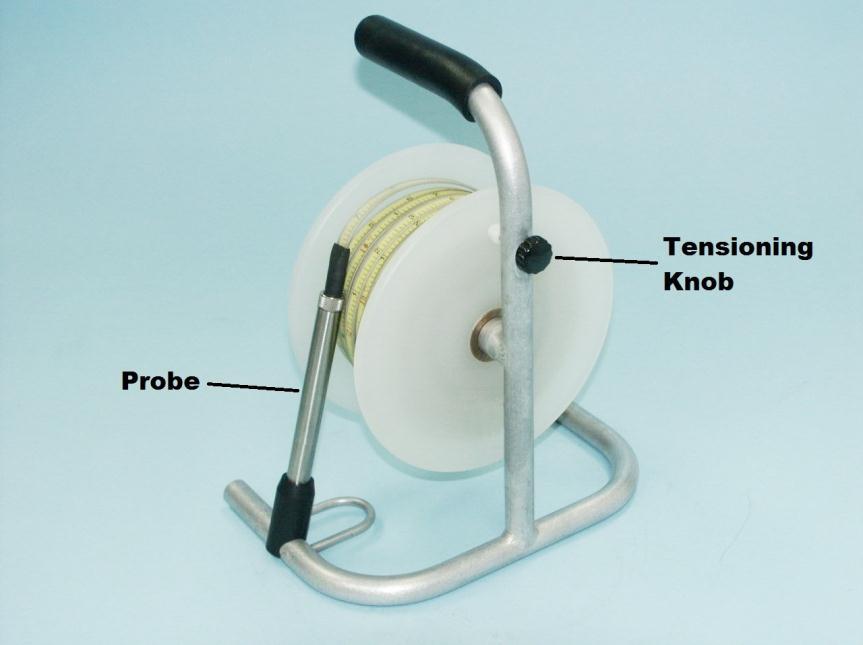
6 Section 1: System Description Function and Theory The Geotech Interface Meter is a hand held, battery powered device for measuring depth to water or oil in tanks or wells. The Interface Meter can be used in numerous applications including measuring oil and water levels in monitoring wells, detecting tank leakage and obtaining accurate measurements of water levels. This manual applies to Geotech Interface Meters with part numbers , , , , , , , , and These models differ in the length of the tape, and the markings on the tape (metric or engineering). Metric tapes are marked in meters and centimeters, engineering tapes in feet and centifeet. The Interface Meter consists of an oil/water sensing probe, a measuring tape, and a reel to wind the tape on. Figures 1-1 and 1-2 are examples of the complete assembly. Figure 1-3 is an example of the faceplate and it s components. The probe contains two different sensor units, one for detecting the liquid/air interface, and one for distinguishing between water and hydrocarbon. The liquid sensor consists of an infrared emitter, a transparent window, and a detector. When in air, most of the light reflects off the window internally and is detected. As long as the detector sees enough light the interface meter is quiet. In liquid, most of the light escapes through the window, even in seemingly opaque fluids. If the detector doesn t pick up enough light, the unit will indicate liquids. The water/hydrocarbon differentiation is made by testing for conductivity. If any current flows between the electrode in the probe tip and the probe body, the probe will indicate water. If no current is detected (or if current flow is below a threshold), the probe indicates hydrocarbons. 4

7 Figure 1-1 Figure 1-2 5

8 Figure 1-3 Interface Meter faceplate 6
9 System Components Probe The probe is a 5/8 inch (15.87mm) diameter stainless steel cylinder which can be used in wells as small as 3/4 inch (19.05mm) diameter. When not in use, the probe is to be placed in the probe holder which will protect the tip. Measuring Tape The tape connects the probe and the reel assembly and provides an accurate means of measuring the distance from the well head or tank port to the air/water, air/oil or oil/water interface. The tape contains all the wires running between the probe and the circuitry in the reel assembly. Reel Assembly The reel assembly contains the control electronics, which includes the battery and the interface indicating LED and buzzer. 7
10 Section 2: System Installation The reel frame has a metal loop called the hanger. The hanger can be used to hang the reel frame onto the well casing (as shown in Figure 2-1). The tape can then slide easily over the side of the reel leg. Figure 2-1 Reel frame on well casing. 8
, as it may fall down the well.")
11 If you are not able to hang the frame onto the well head, then either use the white plastic leader guard (standard with all units), or the optional Tape Guide, to prevent the edge of the well head from damaging the tape. Figure 2-2 is an example of the two parts. Figure 2-2 Tape guides and protectors Do not use the tape leader guard in wells larger than 4 (10cm), as it may fall down the well. 9
12 Section 3: System Operation To turn the unit on, press the switch on the reel faceplate to the ON position and release. While the switch is depressed, the LED will show green and the buzzer will sound. Remove the probe from the probe holder, loosen the tensioning knob, and lower the probe down the well or structure to be investigated. Be sure to install the tape leader guard or optional tape guide onto the well casing prior to deploying the tape (see Section 2.) When the probe contacts liquid, the visual/audible alarm on the reel will be activated. An oscillating alarm indicates water, a continuous alarm indicates hydrocarbon. To determine the exact thickness of a hydrocarbon layer, the probe should be slowly lowered to the air/hydrocarbon interface until the alarm is activated. With the probe at the exact point where the alarm comes on, read the numbers on the tape to determine the distance from the top of the well head to the air/hydrocarbon interface. Next, lower the probe through the hydrocarbon layer and well into the water. An oscillating alarm will be obtained. The probe should then be raised slowly to the hydrocarbon/water interface until the point is reached where the alarm changes from oscillating to continuous, and note the tape reading. The thickness of the hydrocarbon layer is determined by subtracting the first reading from the second reading. The most accurate results are obtained by moving the probe as slowly as possible. It is important that the probe be removed from the fluid slowly. If not, drops of fluid may remain on the probe tip giving a false indication of liquid after it has been removed. The Interface Meter is equipped with an automatic shutoff circuit. When the probe does not stay in contact with liquid for a period of 5 minutes, the unit will automatically turn off to preserve battery life. To turn the unit back on, momentarily press the power switch to the ON position and release. The unit can also be turned off by momentarily pressing the power switch to the OFF position. The LED will show red when the switch is pressed to the OFF position. The buzzer tone and LED also aid in telling you that the electronics are working normally. 10
13 Section 4: System Maintenance The Interface Meter has been designed and manufactured to provide a long, trouble free service life. In order to maximize the life of your probe and prevent voiding the manufactures warranty, proper care and cleaning of the probe is recommended. Things NOT to do: Never scrape or gouge the optical probe end with a sharp object, knife, etc. to clear away any debris. Avoid using abrasive cleaners on optical probe end. Probe senses upper fluid interfaces only, avoid dropping the probe completely to bottom of wells. Avoid dropping the sensor head onto the ground. Be careful not to over tighten the tape reel or put excessive stress on the tapeprobe connection. Battery Replacement Replace the battery when the audible and visible signals become weak or the unit does not operate. 1. Gently remove the battery tray. 2. Remove the old battery and replace it with a new one. Be aware of the polarity (+, -) of the battery when placing the new battery in the tray. Use a 9V alkaline battery only. Cleaning the Optical Probe The optical end of the probe should be periodically cleaned with a non-abrasive cleaner such as isopropyl alcohol, xylene, methanol, Alconox, or Liquinox type cleaner. To clean the sensor probe head, place a small amount of the cleaner on a cotton swab; rub the optical face and around the conductivity sensor wire to remove all foreign matter. Repeat this process until all foreign matter has been removed. 11
14 Section 5: System Troubleshooting Problem: Solution: Unit will not turn on. Replace battery. Ensure the contacts are attached to the correct polarity. Problem: Solution: Unit turns on but will not detect anything. Check tape for kinks and breaks. Problem: Unit turns on but sounds continuously. Solution: Check optics for dirt, clean as necessary (see Section 4). Certain assemblies are field replaceable. Replacement probes, tapes, and faceplate assemblies are available from Geotech. If it isn t clear which assembly is malfunctioning, contact your Geotech representative to further troubleshoot the device or return the unit for repair. For technical assistance, call Geotech Environmental Equipment at or
15 Section 6: System Specifications Probe Material: 316 stainless steel, PTFE, Viton Weight: 4.6 oz (130 g) Diameter:.625 (1.59 cm) Length: (1.66 cm) Minimum detectable hydrocarbon thickness:.0312 (.8 mm) Probe waterproof to: 100 psi (6.9bar) Maximum probe shock: 10 G Conductivity sense range: >.78µS Tape Material: Length/Weight: Accuracy: Kynar coated steel 100 foot (30 meters) = 9 lbs (4 kg) 200 foot (60 meters) = 11 lbs (5 kg) 300 foot (100 meters) = 14 lbs (6.5 kg) 500 foot (152 meters) = 20 lbs (9.1kg) 750 foot (229 meters) = 24 lbs (10.9kg 1000 foot (305 meters) = 28 lbs (12.7kg) (Weight of unit and case) 100th of a foot/100 (3 mm/30.5 meters) Per Federal Specification GGG-T-106E Reel Material: Polypropylene & aluminum ( ) (30 m 100 m) Powder coated steel & aluminum ( ) (152 m 305 m) Size: 13 H x 11 W x 7 D ( ) (33 cm H x 28 cm W x 18 cm D) 15 H x 11 W x 9 D ( ) (38 cm H x 28 cm W x 23 cm D) Battery: Self shut off time: Output tone (hydrocarbons) Output modulation tone (water) 9 volt alkaline 5 minutes 500 Hz typ 3.5 Hz typ Unit Operating temperature range: Storage temperature range: Humidity: F (0 60 C) F ( C) 5-95% non-condensing 13
16 Section 7: System Schematic Figure 7-1 Interface Meter (front view) 14
17 Figure 7-2 Interface Meter (side view) 15
18 Section 8: Replacement Parts List 16
19 Item # Parts Description Parts List 1 ASSY,FRAME,GEOWLM/GIP ASSY,PROBE,GEO IP,5/8",3 WIRE ASSY,TAPE,GEO IP,100FT KYNAR ASSY,TAPE,GEO IP,200FT KYNAR ASSY,TAPE,GEO IP,300FT KYNAR ASSY,TAPE,GEO IP,500FT KYNAR ASSY,TAPE,GEO IP,750FT KYNAR ASSY,TAPE,GEO IP,1000FT KYNAR ASSY,TAPE,GEO IP,30M KYNAR ASSY,TAPE,GEO IP,60M KYNAR ASSY,TAPE,GEO IP,100M KYNAR ASSY,REEL,100FT,GEOWLM ASSY,REEL,200FT,GEOWLM ASSY,REEL,300FT,GEOWLM ASSY,REEL, FT,GEOWLM ASSY,REEL, FT,GEOWLM ASSY,CONTROL,GEO IP,3 WIRE TAPE LENGTH REQUIRED ASSY,CONTROL,GEO IP,3WIRE,500' PROBE HOLDER, 5/8", UNI-FRAME KNOB,KNURLED,3/4X5/16",BLK (USE WITH # ) SCREW,SS8,1/4-20X1.375",SHCS NUT,NYL,1/4-20,HEX KNOB,PHENOLIC,OVAL/TAPERED REEL HANDLE BOLT,SS8,KNOB HANDLE STRIPPER 5/16 X 1.5" (1/4-20 THRD) GUARD,LEADER,PROPAMIDE,NATURAL GUIDE,TAPE,PVC CASE,GEOWLM, ' CASE,GEOWLM, ' MANUAL,GEOTECH IP O-RING, VITON,.480X.039, BROWN WASHER,WAVE
20 NOTES 18
21 NOTES 19
22 The Warranty For a period of one (1) year from date of first sale, product is warranted to be free from defects in materials and workmanship. Geotech agrees to repair or replace, at Geotech s option, the portion proving defective, or at our option to refund the purchase price thereof. Geotech will have no warranty obligation if the product is subjected to abnormal operating conditions, accident, abuse, misuse, unauthorized modification, alteration, repair, or replacement of wear parts. User assumes all other risk, if any, including the risk of injury, loss, or damage, direct or consequential, arising out of the use, misuse, or inability to use this product. User agrees to use, maintain and install product in accordance with recommendations and instructions. User is responsible for transportation charges connected to the repair or replacement of product under this warranty. Equipment Return Policy A Return Material Authorization number (RMA #) is required prior to return of any equipment to our facilities, please call our 800 number for appropriate location. An RMA # will be issued upon receipt of your request to return equipment, which should include reasons for the return. Your return shipment to us must have this RMA # clearly marked on the outside of the package. Proof of date of purchase is required for processing of all warranty requests. This policy applies to both equipment sales and repair orders. FOR A RETURN MATERIAL AUTHORIZATION, PLEASE CALL OUR SERVICE DEPARTMENT AT Model Number: Serial Number: Date of Purchase: Equipment Decontamination Prior to return, all equipment must be thoroughly cleaned and decontaminated. Please make note on RMA form, the use of equipment, contaminants equipment was exposed to, and decontamination solutions/methods used. Geotech reserves the right to refuse any equipment not properly decontaminated. Geotech may also choose to decontaminate the equipment for a fee, which will be applied to the repair order invoice. 20
23
24 Geotech Environmental Equipment, Inc East 40th Avenue Denver, Colorado (303) (800) FAX (303) website:
(450 m-925 m) ET/MDPE Tape Water Level Meter (with optional electric rewind)
 ET/MDPE Tape Water Level Meter (with optional electric rewind)") 1500-3000 (450 m-925 m) ET/MDPE Tape Water Level Meter (with optional electric rewind) Installation and Operation Manual Rev 08/30/12 Part # 12050339 Table of Contents Section 1: System Description.....
1500-3000 (450 m-925 m) ET/MDPE Tape Water Level Meter (with optional electric rewind) Installation and Operation Manual Rev 08/30/12 Part # 12050339 Table of Contents Section 1: System Description.....
Water Level Meter + Temperature
 Water Level Meter + Temperature Installation and Operation Manual Rev 05/23/2017 Part # 12050744 Table of Contents SECTION 1: SYSTEM DESCRIPTION... 3 SECTION 2: SYSTEM INSTALLATION... 6 SECTION 3: SYSTEM
ETL Water Level Meter
 ETL Water Level Meter Installation and Operation Manual Rev 03/03/15 Part # 12050319 Table of Contents SECTION 1: SYSTEM DESCRIPTION... 6 SECTION 2: SYSTEM INSTALLATION... 9 SECTION 3: SYSTEM OPERATION...
Product Recovery Canister
 Product Recovery Canister Installation and Operation Manual PRC 2 PRC 4 Rev. 4/28/2010 Part # 26650319 TABLE OF CONTENTS CHAPTER 1: SYSTEM DESCRIPTION... 5 FUNCTION AND THEORY... 5 SYSTEM COMPONENTS...
Product Recovery Canister
 Product Recovery Canister Installation and Operation Manual Rev 12/18/12 Part # 26650319 Table of Contents Section 1: System Description.... 3 Section 2: System Installation and Operation... 5 Section
SDS Specific. Pump. Installation and Operation Manual. Depth Sampler. Rev. 06/04/12 Part #
 SDS Specific Depth Sampler Pump Installation and Operation Manual Rev. 06/04/12 Part # 11200450 Table of Contents Chapter 1: System Description... p. 02 Function and Theory... p. 02 System Components...
Geotech Hand Pump. Installation Guide. Rev. 2 6/18/02 Part #
 Geotech Hand Pump Installation Guide Rev. 2 6/18/02 Part #87500003 TABLE OF CONTENTS CHAPTER 1: SYSTEM DESCRIPTION... 4 FUNCTION AND THEORY... 4 CHAPTER 2: SYSTEM OPERATION... 5 SIPHONING PROCEDURE...
Geotech Filter Holders
 Geotech Filter Holders Installation and Operation Manual Rev 6/04/12 Part # 23150035 Table of Contents Section 1: System Description.... 3 Section 2: System Installation.. 7 Section 3: System Specifications....
Geotech Hand Pump. Installation and Operation Manual. Rev 1/25/2017 Part #
 Geotech Hand Pump Installation and Operation Manual Rev 1/25/2017 Part # 87500003 Table of Contents Section 1: System Description.... 4 Section 2: System Operation.. 5 Section 3: System Maintenance..
Geotech VFD for Redi-Flo2
 Geotech VFD for Redi-Flo2 Installation and Operation Manual Rev 07/14/2016 Part # 11201299 Table of Contents SECTION 1: SYSTEM DESCRIPTION... 5 SECTION 2: SYSTEM OPERATION... 6 SECTION 3: SYSTEM INSTALLATION...
Geopump Peristaltic Pump Installation and Operation Manual
 Geopump Peristaltic Pump Installation and Operation Manual Rev. 2 5/24/02 Part # 81350020 TABLE OF CONTENTS Chapter 1: System Description... p. 02 Function and Theory... p. 02 System Components... p. 02
Geopump Peristaltic Pump Installation and Operation Manual
 Geopump Peristaltic Pump Installation and Operation Manual Rev. 4 9/14/09 Part # 81350020 TABLE OF CONTENTS CHAPTER 1: SYSTEM DESCRIPTION... 2 FUNCTION AND THEORY... 4 SYSTEM COMPONENTS... 4 CHAPTER 2:
Geotech Geopump Peristaltic Pump
 Geotech Geopump Peristaltic Pump Installation and Operation Manual Rev 7/14/2011 Part # 81350020 Table of Contents Section 1: System Description.... 5 Section 2: System Installation.. 6 Section 3: System
Geopump Peristaltic Pump
 Geopump Peristaltic Pump Installation and Operation Manual Rev 03/31/2017 Part # 81350020 Table of Contents DOCUMENTATION CONVENTIONS... 2 Section 1: System Description... 5 Section 2: System Installation...
HTR-202 INSTRUCTION MANUAL. Portable Digital Height Rod. Befour, Inc. 102 Progress Drive Saukville, WI 53080
 Befour, Inc. 102 Progress Drive Saukville, WI 53080 Phone: 262-284-5150 Toll Free: 1-800-367-7109 Fax: 262-284-5966 Email: mail@befour.com www.befour.com 2014 Befour, Inc. Rev.1 HTR-202 Portable Digital
Instruction Manual Part No
 U O asics MODEL MP30 Draw Down Meter PATENT PENDING Instruction Manual Part No. 95180 5-31-07 P.O. Box 3726 Ann Arbor, MI 48106-3726 USA 1-800-624-2026 Fax (734) 995-1170 info@qedenv.com www.qedenv.com
TX900. Microwave Leakage Detector. 99 Washington Street Melrose, MA Phone Toll Free
 TX900 Microwave Leakage Detector 99 Washington Street Melrose, MA 02176 Phone 781-665-1400 Toll Free 1-800-517-8431 Visit us at www.testequipmentdepot.com Users Manual TX900 Microwave Leakage Detector
Infrared Thermocouple Probe
 80PK-IR Infrared Thermocouple Probe Instruction Sheet 80PK-IR INFRARED TEMPERATURE PROBE 0 to 500 F / -18 to 260 C INTRODUCTION The Fluke 80PK-IR Infrared Thermocouple Probe (the probe) is a noncontact
Sentinel Enteral Feeding Pump. Model: S-1000-SI. Operating Manual
 Sentinel Enteral Feeding Pump Model: S-1000-SI Operating Manual CONTENTS 1. Introduction.. 2 2. Control Panel 5 3. Operating Instructions.. 6 4. Indicators and Alarms.. 9 5. Maintenance.. 10 6. Troubleshooting
MODEL TC400 TIRE CART. Installation, Operation & Repair Parts Information REV P/N:
 MODEL TC400 TIRE CART Installation, Operation & Repair Parts Information REV061614 P/N: 81-0245 1 TABLE OF CONTENTS SAFETY INSTRUCTIONS 2 DEFINITIONS 2 SPECIFICATIONS 3 INSTALLATION INSTRUCTIONS 3 OPERATING
Geotech Product Recovery System
 Geotech Product Recovery System Installation and Operation Manual Rev 11/02/11 Part # 26600008 Table of Contents Section 1: System Description.... 5 Section 2: System Installation.. 6 Section 3: System
(R86049) WARNING: To reduce the risk of injury, the user must read and understand the operator s manual before using this product.
 WARNING: To reduce the risk of injury, the user must read and understand the operator s manual before using this product.") OPERATOR S MANUAL 12 VOLT LITHIUM-ION BATTERY CHARGER 140446001 (R86049) Your charger has been engineered and manufactured to our high standards for dependability, ease of operation, and operator safety.
OPERATOR S MANUAL 12 VOLT LITHIUM-ION BATTERY CHARGER 140446001 (R86049) Your charger has been engineered and manufactured to our high standards for dependability, ease of operation, and operator safety.
INSTALLATION AND MAINTENANCE GUIDE SF1596 B/E ELECTRONIC LAVATORY FAUCET
 INSTALLATION AND MAINTENANCE GUIDE SF1596 B/E ELECTRONIC LAVATORY FAUCET 1 INDEX 1 TECHNICAL DATA 2 PACK CONTENTS 3 PRE-INSTALLATION INFO 4-5 INSTALLATION 6-8 SETTINGS ADJUSTMENT WITH REMOTE CONTROL 9
IR-500 Infrared Thermometer / Voltage Detector / Flashlight
 IR-500 Infrared Thermometer / Voltage Detector / Flashlight Users Manual Mode d emploi Bedienungshandbuch Manual d Uso Manual de uso IR-500 Infrared Thermometer / Voltage Detector / Flashlight English
AC Irrigation and Propagation Controllers I Four Station, 5006-I and 5006-IP Six Station
 AC Irrigation and Propagation Controllers 5004-I Four Station, 5006-I and 5006-IP Six Station I N S T R U C T I O N M A N U A L Table of contents Introduction 1 1. Specifications 1 2. Controller Mounting
Geotech Product Recovery System
 Geotech Product Recovery System Installation and Operation Manual Rev 3/17/2017 Part # 26600008 Table of Contents DOCUMENTATION CONVENTIONS... 2 Section 1: System Description... 3 Function and Theory...
ELECTRONIC FLUSH VALVE FOR URINALS jupiter 2040
 ELECTRONIC FLUSH VALVE FOR URINALS jupiter 2040 InstallatIon and maintenance guide 1 index 1 TECHNICAL DATA 2 PACK CONTENTS 3 PRE-INSTALLATION INFO 4-8 INSTALLATION 9 BATTERY REPLACEMENT INSTRUCTIONS 10-11
Effective June 1, 2013 This guide supersedes all previous versions
 Effective June 1, 2013 This guide supersedes all previous versions 3842 Redman Drive 1-800-797-7974 Fort Collins, CO 80524 www.commandlight.com L-CAS THANK YOU Please allow us to express a simple thank
i n s t r u c t i o n m a n u a l
 i n s t r u c t i o n m a n u a l 8006 Six-Station AC Timer Residential/Light Commercial Independent Program Irrigation Controllers Installation, Programming and Operating Instructions Features Operates
Model P772 Conductivity Meter. User Manual
 Model P772 Conductivity Meter User Manual 1 Table of Contents 1 INTRODUCTION... 1 2 SAFETY SUMMARY... 2 3 COMPLIANCE STATEMENTS... 2 4 PRODUCT CONTENTS AND INSPECTION... 3 5 DEVICE DESCRIPTION... 4 6 OPERATING
Drip-n-Gro Dual Top Feed Drip System Instruction Manual
 Notes: Hydrogardening Bucket Systems Drip-n-Gro Dual Top Feed Drip System Instruction Manual 1 Square = 1 Foot Exclusively distributed by: Exclusively distributed by: www.sunlightsupply.com www.flo-n-gro.net
EXT HEPA/CARBON FUME HOOD
 EXT HEPA/CARBON FUME HOOD POLYPROPYLENE Installation and Operations Manual EXT HEPA/CARBON FUME HOOD Installation and Operations Manual Revision: 28-Jun-18 Page 2 of 12 EXT HEPA/CARBON FUME HOOD Installation
BEFORE YOU BEGIN LIST OF COMPONENTS. Isopropyl SWITCH SCOTCH-BRITE PAD ALCOHOL PREP PAD SWITCH HARNESS REVOLVER PCM COVER STICKER
 User Manual TABLE OF CONTENTS BEFORE YOU BEGIN...3 LIST OF COMPONENTS... 3 REVOLVER INSTALLATION 95-97 Trucks...4 REVOLVER INSTALLATION 98-03 Trucks...7 SWITCH INSTALLATION...12 SAFETY WARNING & CAUTION...14
Junior Sandblaster. Model #51 WARNING! FOR YOUR SAFETY PLEASE READ INSTRUCTIONS BEFORE OPERATING TOOL & WEAR EYE PROTECTION
 Junior Sandblaster Model #51 WARNING! FOR YOUR SAFETY PLEASE READ INSTRUCTIONS BEFORE OPERATING TOOL & WEAR EYE PROTECTION PARTS LIST AND PART NUMBERS 01.Red Rubber Air Hose (5Ft) P51-01 02. Male Insert
KENCOVE PD100 MANUAL TILT POST DRIVER
 OPERATOR S MANUAL KENCOVE PD100 MANUAL TILT POST DRIVER WWW.KENCOVE.COM 800-536-2683 344 KENDALL RD, BLAIRSVILLE, PA 15717 Table of Contents Specifications/Requirements 1 Introduction 2 Equipment Inspection
CONTACT WATERRA. WS-2 REELCASE WATER LEVEL TAPE
 CONTACT WATERRA www.waterra.com www.waterra.com Canada and International Waterra Pumps Limited 5200 Dixie Road, Unit 44 Mississauga, ON L4W 1E4 CANADA tel: 905.238.5242 fax: 905.238.5704 email: sales@waterra.com
VFL-280. Visible Fault Locator. Operating Manual
 VFL-280 Visible Fault Locator Operating Manual Terahertz Technologies Inc. 169 Clear Road Oriskany, New York 13424 TEL: (315) 736-3642 7/2011 Table of Contents Introduction...1 Unpacking and Inspection...1
DT33B/C/D OPERATOR S MANUAL LIMITED WARRANTY AND LIMITATION OF LIABILITY
 BACK LIGHT D I G I TA L M U LT I M E T E R DT33B OPERATOR LIMITED WARRANTY AND LIMITATION OF LIABILITY This product will be free from defects in material and workmanship for one year from the date of purchase.
PVI 1800/PVI Residential/Commercial Grid-Tied Photovoltaic Inverter WARRANTY MANUAL. Subject to Change REV , Solectria Renewables
 PVI 1800/PVI 2500 WARRANTY MANUAL Residential/Commercial Grid-Tied Photovoltaic Inverter 2009, Solectria Renewables Subject to Change REV 10.09 1 Product Warranty & RMA Policy 1.1 Warranty Policy The Solectria
CRD600 Automatic Fitting Inserter
 CRD600 Automatic Fitting Inserter OPERATIONS MANUAL VERSION 2.3 LAST EDITED 12.07.2018 cleanroomdevices.com 1 Table of Contents Title Page.. 1 Table of Contents. 2 1.0 General Product & Safety Information...3
OPERATING MANUAL PLS HLE 1000 PACIFIC LASER SYSTEMS. The Professional Standard
 OPERATING MANUAL PLS HLE 1000 PACIFIC LASER SYSTEMS The Professional Standard TABLE OF CONTENTS Introduction...Page 1 Safety Information...Page 2 Batteries...Page 3 Keypad...Page 4 Functions...Page 5 Applications...Page
362 Clamp Meter. Users Manual
 362 Clamp Meter Users Manual PN 3622678 August 2010, Rev. 1, 4/13 2010, 2013 Fluke Corporation. All rights reserved. Printed in China. Specifications are subject to change without notice. All product names
EXT DUCTLESS FUME HOOD
 EXT DUCTLESS FUME HOOD POLYPROPYLENE Installation and Operations Manual EXT DUCTLESS FUME HOOD Installation and Operations Manual Revision: 1-Feb-16 Page 2 of 12 EXT DUCTLESS FUME HOOD Installation and
SLA Battery Capacity Analyzer
 Model: 600B SLA Battery Capacity Analyzer USER MANUAL Safety Summary The following safety precautions apply to both operating and maintenance personnel and must be followed during all phases of operation,
OPERATING INSTRUCTIONS
 CM OPERATING INSTRUCTIONS 9 Function, Auto Range Digital Multi-Meter DM6450 INTERTEK Read this owner s manual thoroughly before use and save. C LISTED US I. DISPLAY FUNCTIONS & SYMBOLS 9 6 10 11 14 8 7
Go to to register your product and find more information.
 ESA609 Electrical Safety Analyzer Safety Sheet Go to www.flukebiomedical.com to register your product and find more information. Safety Information A Warning identifies hazardous conditions and actions
MODEL 7400 STRUT SPRING COMPRESSOR
 MODEL 7400 STRUT SPRING COMPRESSOR Installation, Operation & Repair Parts Information Branick Industries, Inc. 4245 Main Avenue P.O. Box 1937 Fargo, North Dakota 58103 REV112712 P/N: 81-0103A TABLE OF
TABLE OF CONTENTS. Page 1
 TABLE OF CONTENTS Safety Precautions and Warnings... 2 Introduction... 3 EZ-CHARGE Battery Conductance Testers... 3 EZ-CHARGE 100 Features... 3 EZ-CHARGE 200 Features... 4 Text Styles Used in this Manual...
WATER LEVEL INDICATOR. Model CPR. Roctest Limited, All rights reserved.
 INSTRUCTION MANUAL WATER LEVEL INDICATOR Model Roctest Limited, 2006. All rights reserved. This product should be installed and operated only by qualified personnel. Its misuse is potentially dangerous.
MODEL HD-BTC. Installation, Operation & Repair Parts Information REV041416
 MODEL HD-BTC Installation, Operation & Repair Parts Information REV041416 TABLE OF CONTENTS SAFETY INSTRUCTIONS 1 DEFINITIONS 1 SPECIFICATIONS 2 INSTALLATION INSTRUCTIONS 2 OPERATING INSTRUCTIONS 2 MAINTENANCE
MODEL 7600 STRUT SPRING COMPRESSOR
 MODEL 7600 STRUT SPRING COMPRESSOR Installation, Operation & Repair Parts Information Branick Industries, Inc. 4245 Main Avenue P.O. Box 1937 Fargo, North Dakota 58103 REV6162014 P/N: 81-0246 TABLE OF
Large Display ph Pens , , Instruction Manual
 Large Display ph Pens 850050, 850051, 850052 Instruction Manual Large Display ph Pens - 850050, 850051, 850052 Copyright 2015 by Sper Scientific ALL RIGHTS RESERVED. Printed in the USA The contents of
Operator's Manual. Storage System. Ultrasound Probe Cabinet. Manufactured by:
 Storage System Ultrasound Probe Cabinet Operator's Manual Manufactured by: CIVCO Medical Solutions 102 First Street South Kalona, IA 52247 USA 319.248.6757 / 800.445.6741 WWW.CIVCO.COM Copyright 2018 All
8 Light Controller. Instruction Manual. With Light Timer 240 Volts. Product # INNOVATING SINCE 1995
 8 Light Controller With Light Timer 240 Volts Product #703008 Instruction Manual INNOVATING SINCE 1995 1 www.titancontrols.net 8 Light Controller This manual covers the following: Warnings & Cautions 8
Tachometer. English. Users Manual
 931 Tachometer Users Manual English PN 3409877 January 2009 2009 Fluke Corporation, All rights reserved. Printed in Germany. Specifications are subject to change without notice. All product names are trademarks
CLEAN ROOM DEVICES, LLC "WHERE TUBING AND FITTINGS COME TOGETHER"
 CLEAN ROOM DEVICES, LLC "WHERE TUBING AND FITTINGS COME TOGETHER" CRD600 Automatic Fitting Inserter OPERATIONS MANUAL VERSION 2.1 LAST EDITED 7.25.14 DOCUMENT NUMBER 001 cleanroomdevices.com 1 Table of
Sanitary Yard Hydrant Installation Instructions
 Installation Instructions Freeze Flow hydrants are designed for heavy-duty commercial use where safe potable water is needed. This hydrant drains into the canister below the frost line to prevent freeze
Model 3400KL / 3401KL / 3400KG / 3400KG-C Digital Wet Diaper / Lap Sponge / Organ Scale
 Model 3400KL / 3401KL / 3400KG / 3400KG-C Digital Wet Diaper / Lap Sponge / Organ Scale 3400KL / 3400KG / 3400KG-C 3401KL User Instructions PELSTAR, LLC 9500 West 55 th St. McCook, IL 60525-7110 USA www.homscales.com
CSA products for treated water. Water Combination air valve. Mod. FOX 3F RFP and Lynx 3F RFP
 CSA products for treated water Water Combination air valve Mod. FOX 3F RFP and Lynx 3F RFP Instructions These instructions provide installation, operation and maintenance information for CSA water combination
APCO CRF-100A RUBBER FLAPPER SWING CHECK VALVES
 APCO CRF-100A RUBBER FLAPPER SWING CHECK VALVES Instruction D12043 June 2016 DeZURIK Instructions These instructions provide installation, operation and maintenance information for APCO CRF-100A Rubber
INSTALLATION AND MAINTENANCE GUIDE ELITE SERIES ELECTRONIC LAVATORY FAUCET
 INSTALLATION AND MAINTENANCE GUIDE ELITE SERIES ELECTRONIC LAVATORY FAUCET 1 INDEX 1 TECHNICAL DATA 2 PACK CONTENTS 3 PRE-INSTALLATION INFO 4-5 INSTALLATION 6-9 SETTINGS ADJUSTMENT 10 BATTERY REPLACEMENT
PVI 60KW, PVI 82KW, PVI 95KW
 PVI 60KW PVI 82KW PVI 95KW WARRANTY MANUAL Commercial, Grid-Tied Photovoltaic Inverters 2008, Solectria Renewables LLC Subject to Change DOC-020099 rev 024 1 1 Product Warranty & RMA Policy Warranty Policy
Viking Use/Installation Guide
 Viking Use/Installation Guide Viking Range Corporation 111 Front Street Greenwood, Mississippi 38930 USA (662) 455-1200 For product information, call 1-888-VIKING1 (845-4641) or visit the Viking Web site
SFA275 USER MANUAL PLEASE READ THIS USER MANUAL COMPLETELY BEFORE OPERATING THIS UNIT AND RETAIN THIS BOOKLET FOR FUTURE REFERENCE
 Parking Alert Sensor SFA275 USER MANUAL PLEASE READ THIS USER MANUAL COMPLETELY BEFORE OPERATING THIS UNIT AND RETAIN THIS BOOKLET FOR FUTURE REFERENCE COMPLIANCE WITH FCC REGULATIONS This device complies
DC to DC Step Up Converter Model: VTC305
 DC to DC Step Up Converter Model: VTC305 Owner's Manual Please read this manual before operating your converter INTRODUCTION Step up a 12 VDC battery to between 13.5 and 17.0 or 24.0 and 27.5 VDC in 0.5
INSTALLATION AND MAINTENANCE MANUAL FORM #PM-126 REV A 12/09
 HAND CRANK & MOTORIZED POWER CORD REELS: SERIES 1125PC SERIES: 1125PC HAND CRANK SERIES: 1125PC MOTORIZED COXREELS The technical data and images which appear in this manual are for informational purposes
INSTALLATION & OPERATION MANUAL
 INSTALLATION & OPERATION MANUAL VTC125d-6-12 Voltage Converter An ISO9001 and AS9100 Registered Company Battery Chargers Inverters Power Supplies Voltage Converters 8128 River Way, Delta B.C. V4G 1K5 Canada
Temperature Probe, Battery (installed), Instruction Sheet, Quick Reference Card and Warranty Card.
, Instruction Sheet, Quick Reference Card and Warranty Card.") 80T-IR Infrared Temperature Probe Instruction Sheet Introduction The Fluke 80T-IR Infrared Temperature Probe (the probe) is a noncontact temperature measurement accessory for use with a test instrument
80T-IR Infrared Temperature Probe Instruction Sheet Introduction The Fluke 80T-IR Infrared Temperature Probe (the probe) is a noncontact temperature measurement accessory for use with a test instrument
The Da-Lite Difference.
 The Da-Lite Difference. Instruction Book for tensioned Advantage Electrol DA-LITE SCREEN COMPANY, INC. 3100 North Detroit Street Post Office Box 137 Warsaw, Indiana 46581-0137 Phone: 574-267-8101 800-622-3737
Tiller Lock Assembly
 2 1 4 1 2 4 1 2 4 1 7 6 7 8 Positioning Pin Assembly 1 Positioning Pin 2 Spring Black Knob 5 4 1 2 2 1 Tiller Lock Assembly 1 2 4 Threaded Rod Rotating Rod Spring Flat Washer 5 6 7 8 C Type Plastic Washer
TALON 22 WHEEL & TALON X-TREME 38 WHEEL TPMS, UP to 188 PSI PRESSURE AND TEMPERATURE WITH CAP OR FEEDTHRU SENSORS
 TALON 22 WHEEL & TALON X-TREME 38 WHEEL TPMS, UP to 188 PSI PRESSURE AND TEMPERATURE WITH CAP OR FEEDTHRU SENSORS Thank you for your purchase of The HawksHead TALON OR TALON X-TREME TPMS System With ease
MODEL L/R/EF Sectional Tire Spreader
 MODEL L/R/EF Sectional Tire Spreader Installation, Operation & Repair Parts Information Branick Industries, Inc. 4245 Main Avenue P.O. Box 1937 Fargo, North Dakota 58103 REV08032016 P/N: 81-0195E TABLE
INSTALLATION/OWNERS MANUAL
 INSTALLATION/OWNERS MANUAL XOBP12D PREPARATION Getting Started Thank you for purchasing the Dual Electronics XOBP12D Bandpass Subwoofer System. Although Dual has attempted to make sure all of the information
50407 / DUAL INDEPENDENT FOOTWEAR AND WRIST STRAP TESTER
 50407 / 50413 DUAL INDEPENDENT FOOTWEAR AND WRIST STRAP TESTER INSTALLATION AND OPERATING INSTRUCTIONS 3651 Walnut Avenue, Chino, CA 91710 Phone: (909) 627-8178 Fax (909) 627-7449 DescoEMIT.com TB-6502
AXD 530 MicroManometer
 OWNER S MANUAL AXD 530 MicroManometer A TSI Company Table of Contents Features 2 Using the AXD530 Safely 3 Getting Started 4 Installing Batteries 4 Preparing the Instrument 4 Attaching the Optional Pitot-Static
Instruction Manual. 99 Washington Street Melrose, MA Fax TestEquipmentDepot.com. Model 308A Digital Insulation & Continuity Meter
 Instruction Manual 99 Washington Street Melrose, MA 02176 Fax 781-665-0780 TestEquipmentDepot.com Model 308A Digital Insulation & Continuity Meter INDEX PAGE INSTRUMENT LAYOUT... 1 INTRODUCTION... 2 SAFETY
This manual covers the following model:
 www.skcltd.com chek-mate Air Flowmeter Operating Instructions This manual covers the following model: 375-07550 Purchase Details and Service Record Thank you for choosing an SKC product. Your purchase
Installation Operation Maintenance Troubleshooting Version2.1. Feb/09. Led II
 Installation Operation Maintenance Troubleshooting Version2.1. Feb/09 Led II INDEX Safety Regulation 3 Components 4 User s Guide 9 Product Installation 10 Operation Method 11 Maintenance and Repair 13
Instruction Manual. Single Acting Hydraulic Aluminium Pull Cylinders RAP Series. Maximum Operating Pressure 700 bar
 Single Acting Hydraulic Aluminium Pull Cylinders RAP Series Maximum Operating Pressure 700 bar ABSOLUTE EQUIPMENT PTY LTD 2/186 Granite Street, GEEBUNG QLD 4034 Australia sales@absoluteequipment.com.au
Product Manual. Table of Contents. Innoquest Item # Safety Information Introduction Meter Diagram Features.
 Table of Contents 1.0 Safety Information...2 2.0 Introduction... 3 2.1 Meter Diagram. 3 2.2 Features. 3 Innoquest Item # 25050 3.0 Specifications.. 4 4.0 General Meter Operation... 5 4.1 Battery Replacement...
BP1204 INSTALLATION/OWNER'S MANUAL
 BP1204 INSTALLATION/OWNER'S MANUAL BP1204 PREPARATION Getting Started Thank you for purchasing the Dual Electronics BP1204 Bandpass Subwoofer System. Although Dual has attempted to ensure the information
CRD610 Automatic Fitting Inserter
 CRD610 Automatic Fitting Inserter OPERATIONS MANUAL VERSION 1.2 LAST EDITED 12.12.2018 cleanroomdevices.com 1 Table of Contents Title Page. 1 Table of Contents...2 1.0 General Product & Safety Information....3
INSTRUCTION MANUAL DT173 DT175 DIGITAL THERMOMETERS ALWAYS READ THESE INSTRUCTIONS BEFORE PROCEEDING
 DIGITAL THERMOMETERS INSTRUCTION MANUAL ALWAYS READ THESE INSTRUCTIONS BEFORE PROCEEDING Thank you for buying one of our products. For safety and a full understanding of its benefits please read this manual
Chek-A-Cell TM. Instruction Manual Rev A 8/12
 Chek-A-Cell TM Instruction Manual 84-867 Rev A 8/12 INTRODUCTION: The CHEK-A-CELL is a digital battery load tester for all types of batteries in the 5.75 Volt to 20 Volt, 1 to 20 Amp Hour range. Rechargeable
VLF-275 Visible Laser Fault Locator Operating Manual
 VLF-275 Visible Laser Fault Locator Operating Manual Terahertz Technologies Inc. 169 Clear Road Oriskany, New York 13424 TEL: (315) 736-3642 January 2004 Topic GENERAL INFORMATION Table of Contents Page
INSTALLATION GUIDE. Tenino Retro Pot Filler Hi-Rise Kitchen Faucet PB-K05
 INSTALLATION GUIDE Tenino Retro Pot Filler Hi-Rise Kitchen Faucet PB-K05 RECOMMENDED TOOLS AND MATERIALS Sink Hole Cover (Optional) Allen Wrench Set Plumbers Putty Adjustable Wrench Tape Measure Basin
SUPERPLUS WATER FILTRATION SYSTEM
 SUPERPLUS WATER FILTRATION SYSTEM For Model #: SP20-1 INSTRUCTIONS/ASSEMBLY USE AND CARE MANUAL (Important: Read this manual thoroughly before install) TABLE OF CONTENTS 2 3 4 6 8 9 10 11 12 General Notes
CD42 T-Series 22 Hz Electromagnetic Transmitter
 CD42 T-Series 22 Hz Electromagnetic Transmitter In a hurry? See the QUICK-START Section, Pg. 3 Models CD42-T0, T1A, T1AHP, T1AVHP, T1, T2, T3, T4, & T4VHP USER GUIDE 1801 North Juniper Avenue Broken Arrow,
CAUTION CAUTION indicates a potentially
 Instruction Manual Manual Conventions This manual uses the following symbols to help differentiate between different kinds of information. The safety symbol is used with a key word to alert you to potential
TS69 TS65 TS55 TS45 TS5768 TS SERIES INSTALLATION/OWNER'S MANUAL
 TS69 TS65 TS55 TS45 TS5768 TS SERIES INSTALLATION/OWNER'S MANUAL Car Audio Speakers TS SERIES PREPARATION Getting Started Thank you for purchasing the TS Series car speakers. Although Dual has attempted
Model 616 Rotating Disk Electrode Instruction Manual
 Model 616 Rotating Disk Electrode Instruction Manual 219303 C / 1202 Printed in USA Advanced Measurement Technology, Inc. a/k/a Princeton Applied Research, a subsidiary of AMETEK, Inc. WARRANTY Princeton
INSTALLATION AND MAINTENANCE GUIDE EXTREME WM WALL MOUNTED ELECTRONIC FAUCET FOR COLD OR PREMIXED WATER
 INSTALLATION AND MAINTENANCE GUIDE EXTREME WM WALL MOUNTED ELECTRONIC FAUCET FOR COLD OR PREMIXED WATER Extreme WMB Extreme WME Extreme WMLB Extreme WMLE 1 INDEX 1 TECHNICAL DATA 2 PACK CONTENTS 2 OPERATION
i n s t r u c t i o n m a n u a l
 i n s t r u c t i o n m a n u a l Model 7001 Battery Operated Irrigation Controller with Hose or Pipe Thread Features Weekly or cyclical programming 4 start times per day in weekly program Irrigation duration
DUAL PURPOSE DIAGNOSTIC LEAK DETECTOR
 OPERATION MANUAL DUAL PURPOSE DIAGNOSTIC LEAK DETECTOR P/N 95-030 NIS -800-662-200 nissantechmate.com CONTENTS Specifications / Warranty... Functions...2-3 Accessories... 4 Set-Up... 5 Adaptor Installation...
MODEL G300 BRAKE BLEEDER
 MODEL G300 BRAKE BLEEDER Installation, Operation & Repair Parts Information Branick Industries, Inc. 4245 Main Avenue P.O. Box 1937 Fargo, North Dakota 58103 REV120716 P/N: 81-0035H THIS PAGE INTENTIONALLY
Operating Instructions & Parts Manual. Truck Drain. Model 48UJ80 and 48UJ81
 Operating Instructions & Parts Manual EN Truck Drain Model 48UJ80 and 48UJ81 PLEASE READ AND SAVE THESE INSTRUCTIONS. READ CAREFULLY BEFORE ATTEMPTING TO ASSEMBLE, INSTALL, OPERATE OR MAINTAIN THE PRODUCT
Heavy Duty Four Wheeled Walker
 Heavy Duty Four Wheeled Walker Weight Capacity: 500 lbs. ITEM # W1802 Made in China 2011 ESSENTIAL MEDICAL SUPPLY, INC. Manufactured for Orlando, FL 32822 -- SAVE THESE INSTRUCTIONS -- Do not attempt to
INSTALLATION & OPERATION MANUAL
 INSTALLATION & OPERATION MANUAL VTC140/240 SERIES Voltage Converters An ISO9001 and AS9100 Registered Company Battery Chargers Inverters Power Supplies Voltage Converters 8128 River Way, Delta B.C. V4G
PLS SLD. Laser Detector PACIFIC LASER SYSTEMS. For use with your PLS pulsed laser alignment tool. The Professional Standard
 PLS SLD Laser Detector For use with your PLS pulsed laser alignment tool. 9 PACIFIC LASER SYSTEMS The Professional Standard GENERAL DESCRIPTION IMPORTANT: YOUR PLS SLD DETECTOR IS DESIGNED FOR USE WITH
OPERATION MANUAL MODEL MODEL MODEL MODEL MODEL NON-CONDUCTIVE ARTICULATING FIBERSCOPE INSTRUMENT TECHNOLOGY, INC.
 OPERATION MANUAL MODEL 177704 MODEL 177705 MODEL 177706 MODEL 177708 MODEL 177712 NON-CONDUCTIVE ARTICULATING FIBERSCOPE INSTRUMENT TECHNOLOGY, INC. POB 381, Westfield, MA 01086 33 Airport Road, Westfield,