Ford Expedition High Output Intercooled System Installation Guide
|
|
|
- Osborne Little
- 6 years ago
- Views:
Transcription


1 Ford Expedition High Output Intercooled System Installation Guide
2 2010 Accessible Technologies, Inc. Accessible Technologies, Inc W. 114th Terrace Lenexa, KS Phone: Fax: All rights reserved. Accessible Technologies Inc. hereby grants permission to use and reproduce this document for personal use, provided that all copyright information be retained. Reproduction of this document for unauthorized commercial use is strictly prohibited. Information in this document is subject to change without notice. ProCharger is a registered trademark and The Intercooled Supercharging Experts! TM and Designed to Blow Away the Competition TM are trademarks of Accessible Technologies, Inc. and may not be used without express permission. Revised 9/10 Part Number PMFN1A-005 Rev. B Printed in the USA
3 Congratulations on purchasing your ProCharger Expedition High Output Intercooled System. Read this entire manual before you attempt to install your ProCharger kit. It is imperative that you follow all of the instructions in the order they appear in this installation guide. If you have any questions regarding any aspect of this installation, call us at (913) For best results, we recommend reviewing the installation instructions beforehand, and following the installation instructions closely and in sequence. A detailed packing list has been provided to assist you in identifying the components of your ProCharger system. INTRODUCTION Introduction Required Tools and Supplies 3/8 Socket Set (standard & metric) 1/2 Socket Set (standard & metric) 1/2 Breaker Bar T20 & T30 Torx Bit Open End Wrench Set (standard & metric) 3/8 Hex Bit Set (standard & metric) Flat Screwdrivers Phillips Screwdrivers Plier Set Loctite 272 Drill and 1/2 Drill Bit Solder & Soldering Iron Heat Gun Warning: Your supercharged F-150 must always be run on 91 octane or better gas. You should also have the following gauges available to properly check the finished installation and monitor your vehicle s performance (especially for testing): Manifold Boost Pressure Gauge Fuel Pressure Gauge Wide Band Oxygen Sensor and Gauge Gauges should be of a type that can be read from the cockpit while performing a wide-open throttle road test. Cockpit or hood-mounted gauges are preferable. In order to obtain usable readings, the gauges should measure pressure at the intake manifold and fuel rail. IF VEHICLE DOES NOT MAINTAIN PROPER FUEL PRESSURE (50-65 PSI), DECREASE THROTTLE APPLICATION IMMEDIATELY. In some cases, extra vehicle modifications can strain the stock fuel pump. If your vehicle has difficulty retaining adequate fuel pressure, contact ATI ProCharger about the availability of an upgraded fuel system. The engine on which the ProCharger is to be installed should retain the factory compression ratio. If it has been modified in any way, please consult ProCharger staff before proceeding with the installation. This supercharger system is intended for use on STOCK, strong, well-maintained engines/transmissions. Installation on a worn or troublesome powertrain should be reconsidered. ATI PROCHARGER WILL NOT BE HELD RESPONSIBLE FOR DAMAGE TO A VEHICLE S POWERTRAIN. ATI ProCharger is not responsible for ECM tuning/programming on non-stock vehicles. ATI PROCHARGER recommends verifying that your vehicle has current ECM updates from the vehicle manufacturer before installation. For best performance and reliability, always use premium grade fuel (91 octane or higher) and listen closely for signs of detonation, which might sound like ball bearings rolling around in a tin can. IF DETONATION SHOULD OCCUR, OR IF YOU ARE UNSURE WHETHER WHAT YOU RE HEARING IS DETONATION, DECREASE THROTTLE APPLICATION IMMEDIATELY and please consult ATI ProCharger staff. Detonation should not be an issue with a properly installed intercooled supercharger system, though OEM factory-shipped engine and parts inconsistencies are possible on any vehicle. i
4 Introduction TABLE OF CONTENTS Introduction... i Table of Contents...ii Getting Started... 1 Main Bracket Assembly... 9 Intercooler and Tubing Vacuum Manifold MAF Wiring Harness PCV System Coolant Tank and P/S Reservoir...24 Final Assembly Tuning Operation and Maintenance...28 Limited Warranty ProCharger Extended Coverage Notes ii
 Coolant Resevoir (E) Engine Cover Read and understand all safety precautions in this manual before installation.")
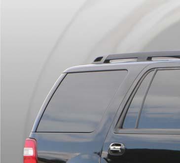
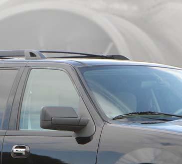
5 Getting Started GETTING STARTED E C D B A Completion of this section will configure the vehicle for system installation: (A) Factory Air Filter Box (B) Mass Airflow (MAF) Sensor (C) Factory Inlet Pipe (D) Coolant Resevoir (E) Engine Cover Read and understand all safety precautions in this manual before installation. Failure to comply with instructions in this manual could result in personal injury, property damage, and/ or voiding your warranty. 1

 wiring harness from the intake tube by first pulling out the red locking tab and then pressing in the")

6 Getting Started 1 Disconnect the negative battery cable from the battery using a 10mm wrench. 2 Remove the two bolts from the engine cover and remove the engine cover. Remove the twelve fasteners from the radiator cover and remove the radiator cover. 3 Disconnect the Mass Airflow Meter (MAF) wiring harness from the intake tube by first pulling out the red locking tab and then pressing in the center tab and pulling out. Remove Engine Cover & Radiator Cover 4 Loosen the two hose clamps (5/16 ) on the intake tube and remove the intake tube. 5 Unclip the retainers and remove the upper portion of the air filter box and the air filter. 6 Using a T20 Torx bit, remove the MAF sensor from the air filter box and set aside for reuse later. The rest of the intake system will not be re-installed. Disconnect MAF Harness From Intake Tube & Remove Intake Tube Remove MAF Sensor From Air Filter Box 2


7 Getting Started 7 Unhook the PCV hose from the passenger s side of the throttle body intake. 8 Remove the four bolts (10mm) and remove the throttle body intake. Warning: Do not remove the coolant reservoir pressure cap, overflow hose or return hose when the engine is hot or steam and liquid may be released, resulting in severe burns. Remove the Throttle Body Intake 9 When the engine is cool, relieve pressure on the coolant system by removing the pressure cap on the reservoir. Tech Tip: Drain the coolant from the radiator to make these steps cleaner if desired. 10 Disconnect the overflow hose from the coolant reservoir. 11 Disconnect the return hose from the coolant reservoir. Disconnect Return Hose 12 Remove the two mounting bolts (13mm) and remove the air filter box/coolant reservoir. Remove the Air Filter Box/Coolant Reservoir 3
 and place it out of the way next to the brake reservoir. Replace the stud and secure the wiring harness.")

8 Getting Started 13 Remove the driver s side air deflector. 14 Remove the wiring harness from the stud holding the power steering reservoir. Remove the power steering reservoir from the radiator shroud (10mm) and place it out of the way next to the brake reservoir. Replace the stud and secure the wiring harness. 15 Remove the passenger s side PCV hose from the valve cover. Plug the valve cover tube with the supplied 3/8 vacuum cap and secure with a #4 hose clamp. Remove Air Deflector 16 Remove the driver s side PCV hose from the intake manifold and the valve cover. Plug the intake manifold tube with the supplied 5/8 vacuum cap and secure with a #10 hose clamp. Unbolt Power Steering Reservoir Remove PCV hoses 4
 from the engine.")
 from the driver s and passenger s side headlights,")
 from the upper grill")
9 Getting Started 17 Remove the nut (15mm) holding on the ignition coil capacitor and then remove the stud (18mm) from the engine. 18 Remove the engine front cover bolt (18mm) that is directly above the power steering pump. 19 Remove the two bolts (10mm) from the driver s and passenger s side headlights, pull the headlights forward, unhook the wiring harnesses, and remove the headlights. Remove Stud & Bolt from Engine 20 Remove the four bolts (T30) from the upper grill supports. Remove Headlights Remove Upper Grill Support Bolts 5


10 Getting Started 21 Remove the push-in retainers from the driver s and passenger s air deflectors. 22 Remove the two bolts (10mm) from the driver s and passenger s inner fender that secure the bumper cover to the front fenders. Remove Air Deflector Retainers Remove Lower Bumper Cover Bolts 6


11 Getting Started 23 Remove the two screws (7mm) from the driver s and passenger s wheelwell that secure the bumper cover to the front fenders. 24 Unhook the driver s and passenger s fog light wiring harness. 25 Ensure that the pins on the bumper cover in the inner fender are down and out of the fender. Pull the grill and bumper cover forward to release them from the clips and lower to ground. Remove Bumper Cover Screws 26 Remove the two push-in retainers from the lower bumper cover air deflector and remove the grill and bumper cover. Unhook Fog Light Wiring Harness 7


12 Getting Started 27 Cut the factory coolant return hose 2-3 behind the fitting, install the supplied coupler and extension hose and secure with two #24 hose clamps. 28 Drain the power steering fluid from the reservoir. Remove the 3/8 line, install the coupler and extension hose and reinstall on the reservoir as shown. Route the line under and around the brake lines as shown. Secure with three #4 hose clamps. 29 Remove four bolts (10mm) from the alternator mounting bracket and discard. Cut Return Hose and Install Extension 30 Install four spacers under the alternator mounting bracket and secure with four M6 X 35mm bolts and thick washers. Power Steering Extension Hose Install Spacers Under Alternator Bracket 8


13 Main Bracket Assembly MAIN BRACKET ASSEMBLY 1 Remove the factory belt and discard. 2 Remove the factory idler and mount to the supplied bracket. 3 Install the supplied belt and leave slack where the ProCharger mounts. Warning: Belt must be installed prior to bracket installation. Remove Idler Pulley Main Bracket Assembly 9


14 Main Bracket Assembly 4 Connect the bracket to the engine using the two supplied M8 X 110mm hex head cap screws (these will mount where the studs were that were previously removed) and one M10 X 30mm socket head cap screw and spacers. Install the ignition coil capacitor behind the top left spacer. Tighten all three fasteners. 5 Once assembled, make sure the wire on the ignition coil capacitor is not in the belt path and zip tie it to the factory wiring harness. 6 Mount the ProCharger onto the main bracket using the supplied 5/16-18 X 3/4 and 3/8-16 X 7/8 socket head cap screws. Tighten all eight fasteners. Main Bracket Mounted PROCHARGER ADJUSTABLE IDLER 7 Raise the adjustable idler tensioner to the top position to aid in belt installation by loosening the locknut and then turning the allen screw clockwise. ALT IDLER IDLER IDLER 8 Finish installing the supplied belt. WATER PUMP 9 Tension the belt by turning the allen screw counter-clockwise until the factory tensioner is near the stop on the right, but still allowing it to float. A/C COMPRESSOR TENSIONER CRANK IDLER POWER STEERING Belt Routing Diagram 10 Tighten the locknut on the adjustable idler shaft to lock it in position. 11 Fill the ProCharger with one 6 ounce bottle of oil supplied with system. Factory Tensioner 10

15 2 CORE INTERCOOLER AND INSTALLATION Intercooler and Tubing 2 CORE INTERCOOLER SCHEMATIC 11


16 Intercooler and Tubing Tech Tip: To ease installation, leave hose clamps and brackets loose until all tubes have been positioned. Trim rubber connectors as desired after test fitting all tubing to determine proper length required. 3 Core Installation starts on page 16 1 Remove the plastic cover from the hood latch and discard. 2 Remove the two bolts (10mm) from the hood latch. Remove Plastic Cover and Bolts 3 Install the upper intercooler bracket behind the hood latch and install the two bolts removed in the previous step. 4 Install the driver s and passenger s side lower intercooler brackets onto the lower bumper mounting bolts, on top of the factory nut, and secure using two M12 nuts. Upper Intercooler Bracket Installed Lower Intercooler Bracket Installed 12

 to the 90 surge tube (#278) using a 3 rubber coupler and two #52 hose clamps.")
17 Intercooler and Tubing 5 Mount the intercooler using four 3/8-16 X 7/8 socket head cap screws with washers. Tech Tip: All hose connections for the intercooler tubing will utilize the #52 hose clamps except the couplers which connect to the 3-1/2 intake tube. Use the #64 hose clamps for this tube. 6 Connect the ProCharger to the blower discharge tube (#277) using a 3 rubber coupler and two #52 hose clamps. Intercooler Installed 7 Connect the blower discharge tube (#277) to the 90 surge tube (#278) using a 3 rubber coupler and two #52 hose clamps. 8 Connect the 90 surge tube (#278) to the 3 X 7 tube (#031) using a 3 90 rubber coupler and two #52 hose clamps. 9 Connect the 3 X 7 tube (#031) to the intercooler using a 3 90 rubber coupler and two #52 hose clamps. Blower Discharge and Intercooler Inlet 13
 to the offset intercooler discharge tube (#280) using a 3 45 rubber coupler and two #52 hose clamps.")
18 Intercooler and Tubing 10 Connect the offset intercooler discharge tube (#280) to the intercooler using a 3 rubber coupler and two #52 hose clamps. 11 Connect the twisted 45 & 90 tube (#022) to the offset intercooler discharge tube (#280) using a 3 45 rubber coupler and two #52 hose clamps. 12 Mount the factory MAF sensor to the bung located on the supplied throttle body tube (tube #281). Use the supplied M4 X 12mm hex head cap screw with a 7mm nut driver for installation. Be sure the arrow located on the MAF points towards the throttle body. Intercooler Outlet Factory MAF Installed in Intake Tube 14
 to the throttle body using a 3-1/2 rubber coupler and two #64 hose clamps. 15 Secure all connections with the provided hose clamps.")
19 Intercooler and Tubing 13 Connect the intake tube (#281) to the twisted 45 & 90 tube (#022) using a 3 to 3-1/2 rubber coupler and one #52 hose clamp and one #64 hose clamp. 14 Connect the intake tube (#281) to the throttle body using a 3-1/2 rubber coupler and two #64 hose clamps. 15 Secure all connections with the provided hose clamps. 16 Connect the ProFlow surge valve to the 1-1/2 bung on the 90 surge tube (#278) using the 1-1/2 rubber hose and two #24 hose clamps. Twisted Tube to Intake Tube (Passenger Side) 17 Install the supplied air filter onto the ProFlow surge valve and secure with the supplied hose clamp. Intake Tube ProFlow Installed 15

20 Intercooler and Tubing 3 CORE INTERCOOLER AND INSTALLATION 3 CORE INTERCOOLER SCHEMATIC 16


21 Intercooler and Tubing Tech Tip: To ease installation, leave hose clamps and brackets loose until all tubes have been positioned. Trim rubber connectors as desired after test fitting all tubing to determine proper length required. 1 Remove the plastic cover from the hood latch and discard. 2 Remove the two bolts (10mm) from the hood latch. 3 Install the upper intercooler bracket behind the hood latch and install the two bolts removed in the previous step. Remove Plastic Cover and Bolts 4 Install the driver s and passenger s side lower intercooler brackets onto the lower bumper mounting bolts, on top of the factory nut, and secure using two M12 nuts. Upper Intercooler Bracket Installed Lower Intercooler Bracket Installed 17

 to the 90 surge tube (#278) using a 3 rubber coupler and two #52 hose clamps.")
22 Coolant Intercooler Hose and Tubing 5 Mount the intercooler using four 3/8-16 X 7/8 socket head cap screws with washers. Tech Tip: All hose connections for the intercooler tubing will utilize the #52 hose clamps except the couplers which connect to the 3-1/2 intake tube. Use the #64 hose clamps for this tube. 6 Connect the ProCharger to the blower discharge tube (#277) using a 3 rubber coupler and two #52 hose clamps. Intercooler Installed 7 Connect the blower discharge tube (#277) to the 90 surge tube (#278) using a 3 rubber coupler and two #52 hose clamps. 8 Connect the 90 surge tube (#278) to the intercooler using a 3 rubber coupler and two #52 hose clamps. Blower Discharge and Intercooler Inlet 18
 to the 3 X 7 tube (#031) using a 3 90 rubber coupler and two #52 hose clamps.")
23 Intercooler Coolant and Tubing Hose 9 Connect the 3 X 7 tube (#031) to the intercooler using a 3 90 rubber coupler and two #52 hose clamps. 10 Connect the 6 90 tube (#279) to the 3 X 7 tube (#031) using a 3 90 rubber coupler and two #52 hose clamps. 11 Connect the twisted 45 & 90 tube (#022) to the 6 90 tube (#279) using a 3 45 rubber coupler and two #52 hose clamps. Intercooler Outlet 12 Mount the factory MAF sensor to the bung located on the supplied throttle body tube (tube #281). Use the supplied M4 X 12mm hex head cap screw with a 7mm nut driver for installation. Be sure the arrow located on the MAF points towards the throttle body. Factory MAF Installed in Intake Tube 19
 to the throttle body using a 3-1/2 rubber coupler and two #64 hose clamps. 15 Secure all connections with the provided hose clamps.")
24 Coolant Intercooler Hose and Tubing 13 Connect the intake tube (#281) to the twisted 45 & 90 tube (#022) using a 3 to 3-1/2 rubber coupler and one #52 hose clamp and one #64 hose clamp. 14 Connect the intake tube (#281) to the throttle body using a 3-1/2 rubber coupler and two #64 hose clamps. 15 Secure all connections with the provided hose clamps. 16 Connect the ProFlow surge valve to the 1-1/2 bung on the 90 surge tube (#278) using the 1-1/2 rubber hose and two #24 hose clamps. Twisted Tube to Intake Tube (Passenger Side) 17 Install the supplied air filter onto the ProFlow surge valve and secure with the supplied hose clamp. Intake Tube ProFlow Installed 20

25 Vacuum Manifold VACUUM MANIFOLD 1 Connect one end of the vacuum line to the barb fitting on the ProFlow. 2 Route the vacuum line along the inner fender support rail. 3 Assemble the vacuum manifold as shown, using thread sealant on fittings. If installing a manifold pressure gauge, substitute a barb fitting for the plug in the upper side port. 4 Remove the factory vacuum line from the brake booster and install the vacuum manifold using the supplied hose and two #4 hose clamps. Warning: Improper installation of the vacuum line onto the brake booster could cause a vacuum leak and could cause the power brakes to become inoperable. Use extreme caution in installing the vacuum line to prevent any possible leaks. 5 Connect the end of the vacuum line from the ProFlow to the lower side barb fitting. Vacuum Manifold Installed 7 If installing a manifold pressure gauge, connect the vacuum line from the gauge to the upper side fitting. 8 Loosely secure the vacuum line with zip ties. Warning: Ensure vacuum line is free of kinks and is not pinched by zip ties or ProFlow will be inoperable and may result in damage to ProCharger from surging. 6 Connect the factory vacuum line to the middle side barb fitting. 21

26 MAF Wiring Harness MAF WIRING HARNESS 1 Verify that the battery is disconnected. 2 Connect the supplied MAF harness to the factory harness near the radiator shroud on the driver s side and push in the red retainer to lock. 3 Route the MAF wiring harness along the inner fender support rail, then over to the MAF sensor in the intake tube. 4 Connect the MAF plug to the MAF sensor and push in the red retainer to lock. MAF Wiring Harness Connected to Sensor 5 Secure the MAF wiring harness with zip ties. 22


27 PCV System PCV SYSTEM 1 Attach the supplied 5/8 hose to the driver s side valve cover and secure with a #10 hose clamp. 2 Drill a 1/2 hole in the end of the air filter. 3 Install the 5/8 90 barb fitting in the end of the air filter. 4 Route the 5/8 hose over the blower discharge tube, attach it to the fitting installed in the air filter and secure with a #10 hose clamp. PCV Line Connected to Valve Cover (2) PCV BUNGS WITH STOCK LINES REMOVED PCV Line Installed in Air Filter 23


.")
28 Coolant Tank & P/S Reservoir COOLANT TANK AND POWER STEERING RESERVOIR 1 Place the supplied coolant tank along the driver s side inner fender, inserting the lower mounting pin into the factory rubber bushing. 2 Secure the tank to the inner fender using two M8 X 20mm bolts with washers. 3 Trim the factory overflow hose as required and connect to the barb fitting on the coolant tank; secure with a #4 hose clamp. Mount to Inner Fender & Connect Overflow 4 Connect the return extension hose to the coolant tank and secure with a #24 hose clamp. 5 Mount the power steering reservoir to the bracket on the coolant tank using the supplied M6 X 20mm bolt, washers and locknuts. 6 Refill the power steering reservoir with Ford approved fluid (refer to vehicle s owner s manual). Connect Return Hose & Install P/S Reservoir 7 Refill the coolant system with a 50/50 blend of Ford approved engine coolant (refer to vehicle s owner s manual) and distilled water. Re-install the factory pressure cap on the coolant tank. 24 Coolant Tank and P/S Reservoir Installed
 into the air filter with the supplied hose clamp in place.")


29 Final Assembly FINAL ASSEMBLY 1 Slide the supplied 3-1/2 short 90 rubber coupler onto the blower inlet and slide two #64 hose clamps onto the coupler. 2 Slide the 3-1/2 coupler tube (#068) into the air filter with the supplied hose clamp in place. 3 Slide the air filter with tube into the 90 coupler as shown, adjust as needed and tighten all hose clamps. Air Inlet Assembly Installed 4 Install the intake cover base by rotating 90 forward and 90 clockwise from the installed position. Placing the right leg under the intake tube, slide it into position and rotate 90 counterclockwise and 90 back into the installed position. 5 Install four M6 X 20mm hex head cap screws with washers into the intake manifold on the inside of the base and tighten all fasteners. Intake Cover Base Installed 6 Slide the top cover into position under the intake tube on top of the base. 7 Install four 1/4-20 X 3/4 button head cap screws with rubber washers facing the cover face and tighten all fasteners. Intake Cover Installed 25

30 Final Assembly 8 Re-install the grill and bumper cover, headlights and radiator cover. 9 Reconnect the negative battery cable to the battery. CONGRATULATIONS! YOU HAVE COMPLETED THE INSTALLATION OF YOUR NEW PROCHARGER SUPERCHARGER SYSTEM. FOR FULL SYSTEMS, TUNING INSTRUCTIONS ARE ON THE FOLLOWING PAGE. IF YOU DO NOT HAVE A FULL SYSTEM, ADDITIONAL TUNING WILL BE REQUIRED BEFORE STARTING THE VEHICLE. READ THE FOLLOWING PAGES CAREFULLY FOR OPERATION AND MAINTENANCE INSTRUCTIONS, AS WELL AS WARRANTY INFORMATION. 26
31 Tuning TUNING Note: This section only applies to full systems, which include a hand-held tuner for tuning. If you do not have a full system, additional tuning will be required before starting the vehicle. 1 Remove the hand-held tuner from it s box and review the included instructions. Note: You will be prompted to turn the key on and off; this is normal, but do not try to start the car. 2 Connect the hand-held tuner to the OBD-II port located under the dash near the driver s door. 3 Your hand-held tuner comes preprogrammed with the appropriate tune for your vehicle. Select Custom Tune from the Main Menu and follow the on-screen instructions. 4 The user adjustable parameters allow you to fine tune your car and adjust for tire size and axle ratio. Changes to spark and fuel are advanced parameters and should only be adjusted by knowledgeable users. Troubleshooting: If the programmer displays an error message, reprogram the vehicle with Return to Stock option rather than Custom Tune before reattempting to install the Custom Tune. Voltage fluctuations are a common cause of reflashing failure. Be sure your battery is fully charged, remove the cooling fan and fuel pump fuses, keep the stereo off, and do not open or close any doors or windows while reflashing. Some vehicles will lock the doors during a reflashing; either stay in the car or open a window prior to reflashing to prevent getting locked out. Another common cause of reflashing failure is a computer that has been reflashed by a dealer to an updated calibration. Your vehicle s calibration can be verified by choosing Read Strategy from the DTC/Data Menu. If you have persistent tuning issues, read the strategy prior to contacting ATI Technical Support. \ 27
32 Operation and Maintenance OPERATION AND MAINTENANCE Cold Starting Never race your engine and ProCharger supercharger when your engine is cold. Allow the water temperature to climb into operating range for several minutes before driving above 2,500 rpm, to ensure adequate oil lubrication. Fuel Quality With a properly installed intercooled ProCharger supercharger system, detonation should not occur. For the best performance and reliability, use premium grade fuel (91 octane or higher). Listen for signs of detonation after refueling, and after replacement or modification of any fuel system component(s). If detonation occurs, reduce the throttle and locate the source. Ignition System Maintenance If your spark plugs are more than a year old or have more than 10,000 miles logged, you should consider changing them before driving your vehicle under load. Spark plug wires should be changed if visibly damaged or when resistance exceeds factory specifications. Air Filter Maintenance Your air filters should be cleaned periodically, potentially as often as every 10,000 miles or 6 months, even though a service interval of 50, ,000 miles is quoted by the manufacturer under normal driving conditions. A clogged air filter will result in decreased boost levels and vehicle performance. Be sure to reoil the cleaned filter before re-installing. Always operate your vehicle with an air filter; failure to do so may result in damage to your ProCharger supercharger and personal injury! Belt Replacement The serpentine belt, which turns your ProCharger supercharger, will stretch after initial run-in, and should be retightened after the first hundred miles. Tighten the belt sufficiently to avoid slippage, but do not overtighten. Overtightening the belt could cause damage to the ProCharger supercharger s precision bearings. When reinstalling the belt, use the belt routing diagram in this manual. If you reuse a thrown belt and find that it needs frequent re-tightening, the belt is damaged and should be replaced. Gates Micro-V belts can be bought from ATI or from your local parts store. ProCharger Oil Change Intervals The first oil change should be performed at 500 miles and at 6,000 mile intervals thereafter. Clean drain plug after every oil change. Drain oil by removing the drain plug. Clean off drain plug before re-installing. 28
 and maximum (MAX) indicators at all times.")

33 Operation and Maintenance ProCharger Oil Level The ProCharger supercharger s oil level must be checked periodically to ensure the proper lubrication. The dipstick can be loosened using a flat blade screwdriver or a coin. When installed, the oil level should remain between the minimum (MIN) and maximum (MAX) indicators at all times. Warning: Filling the ProCharger higher than the maximum level on the dipstick can lead to bearing and seal damage. The supercharger is a sealed unit and should not normally require the addition of oil between service intervals. If excessive usage is noted, the unit should be sent to ATI for inspection and repair. The dipstick fitting should be firmly tightened after changing or checking the oil level. General When removing the warning tag from the dipstick, be sure to retain the nylon washer. A spare nylon washer and o-ring is included. Use only the ATI supplied nylon washer and o-ring when servicing the oil dipstick and drain plug. A discoloration of the oil and residue on the drain plug may occur during the initial oil changes. This is normal and will gradually decrease. For the proper positioning of the ProCharger supercharger, the serial tag should be pointing upwards. Installing the ProCharger supercharger in another position will cause inadequate oiling and supercharger failure. If you have any questions about the maintenance of your supercharger, contact ATI. Sealed Plug (socket head) Magnetic Drain Plug (hex head) Sealed Plug (socket head) Dipstick (flat head) 29
34 Limited Warranty LIMITED WARRANTY Accessible Technologies, Inc. (ATI) provides a limited twelve (12) month warranty on the ProCharger supercharger against defects in materials and workmanship unless otherwise specified. This limited warranty starts on the date of original purchase from your local dealer, or date of shipment from the factory. This limited warranty coverage is extended only to the original owner and excludes hoses, sleeves, and electronic components manufactured by other companies. IF THE SUPERCHARGER S DRIVE RATIO IS ALTERED IN ANY WAY FROM THE FACTORY SETTING, WARRANTY COVERAGE IS VOID. USE OF ANY PULLEY NOT MANUFACTURED OR SUPPLIED BY ATI VOIDS ALL WARRANTY COVERAGE. ATI s warranty obligations are limited to the terms below: ATI agrees to honor a warranty claim at its sole discretion and only after inspection at the ATI factory. No warranty will be honored if any part of the product is found to have been improperly installed, tampered with, mishandled, or misused in any way. Disassembly of the ProCharger supercharger or removal of the ProCharger supercharger s serial number plate voids all warranties. Claims for freight damages should be directed to the freight company. If ATI s limited warranty applies, your product will be repaired or replaced at ATI s discretion and shipped back. If the limited warranty does not apply, ATI will advise you of the specific reason, cost of the repair, and delivery time. After advising you of this information we will, at your option, either proceed with repairs or return your product to you in the state in which it was received. In either case the product will be shipped to you, insured at replacement value. Therefore, you will pay the return shipping and insurance charges if ATI s limited warranty does not apply to your product. THE WARRANTY AND REMEDIES SET FORTH ABOVE ARE EXCLUSIVE AND IN LIEU OF ALL OTHERS, ORAL OR WRITTEN, EXPRESS OR IMPLIED. THE DURATION OF ANY AND ALL WARRANTIES ON THE PRODUCTS DISCUSSED ARE LIMITED TO THE PERIOD IDENTIFIED ABOVE. ATI IS NOT RESPONSIBLE IN ANY EVENT FOR DIRECT, SPECIAL, INCIDENTAL OR CONSEQUENTIAL DAMAGES. No ATI dealer, agent, or employee is authorized to make any modification, extension, or addition to this warranty. To obtain service under this warranty you must do the following during the warranty period: Phone ATI ( ) and provide us with the following information: - ProCharger supercharger serial number. - Vehicle year, make, model, engine modifications, and other modifications. - Description of perceived issue. If a solution to your issue can not be found after the above phone consultation, you will be assigned a return authorization number (RMA). You must then properly pack and ship your product, at your expense, to the ATI factory. The product should be carefully packaged in a rugged box. Include the following information inside the box with your product: - Copy of your original invoice or receipt. - Name, address, and daytime telephone number. - Return authorization number (RMA). - Vehicle year, make, model, engine modifications, and other modifications. - Description of perceived issue. Clearly mark the warranty claim number on the top and one side of the box in characters at least 2 tall. Properly package the product and ship it, prepaid and insured for the retail value of the component(s) being returned, to the following address: Accessible Technologies, West 114th Terrace, Lenexa, Kansas
35 ProCharger Extended Coverage PROCHARGER EXTENDED COVERAGE The ProCharger Extended Coverage Program extends the ProCharger warranty coverage for an additional twenty-four (24) months, for a total of thirty-six (36) months or three years of coverage. This extended coverage applies to parts for the ProCharger supercharger head unit only and does not include other system components. With your extended coverage registration, you will receive two (2) additional boxes of ProCharger Supercharger oil. Under the extended coverage program, Accessible Technologies, Inc. (ATI) will repair or replace any component within the supercharger head unit which is found to be defective. Only the supercharger head unit itself is included in the extended coverage. Service under the extended coverage program is obtained through the same process as described in the Limited Warranty. Race kits are not eligible for the ProCharger Extended Coverage Plan. To qualify for the ProCharger Extended Coverage: Only the original owner of the ProCharger supercharger is eligible (extended warranty is non-transferable). Completion of the Extended Coverage Registration Form is required, along with a $49 registration fee. This form must be completed in its entirety, and must be submitted along with payment within 30 days from the date of original purchase from your local dealer or date of shipment from the factory. Participants must have a ProCharger P-1SC, P-1SC-1, C1, or C2 supercharger head unit using the maximum warranted boost level. All terms and conditions within The Limited Warranty apply. Acts resulting in disqualification include but are not limited to the following: - Disassembly or modification the ProCharger supercharger. - Removal or attempted removal of the ProCharger drive pulley(s). - Removal or attempted removal of the ProCharger supercharger serial number plate. - Removal or attempted removal of the compressor housing or transmission case. Participants agree to properly maintain the ProCharger supercharger and provide proof of compliance with the following recommended maintenance: - Change the ProCharger supercharger oil after the initial break-in period of 500 miles (automotive) or 15 hours (marine). - Change the ProCharger supercharger oil every 6,000 miles after the initial breakin period. - Use only the specified amount of ProCharger Supercharger oil in the ProCharger supercharger. - Inspect and clean the magnetic drain plug at every ProCharger supercharger oil change. - Check the ProCharger supercharger oil level frequently. 31
36 Notes 32
37 ProCharger Extended Coverage Program Registration Form Return this completed form and a $49 check within 30 days of original purchase. cut along the dotted line cut along the dotted line Name: Address: City: State: Zip: Daytime phone: Evening phone: Age and up Income $15,000 - $29,000 $30,000 - $44,000 $45,000 - $69,000 $70,000 and up What magazines do you read? Car & Driver Car Craft Chevy High Performance Four Wheel and Off Road Hot Rod Motor Trend Muscle Mustangs and Fast Fords GM High-Tech Performance 5.0 Mustang Super Street Mustang Monthly Truck Trends Popular Hot Rodding Road & Track Sport Truck Super Chevy Truckin Sport Compact Car Street Truck Date of Purchase: Purchased From: ProCharger Serial #: Vehicle Year: Vehicle Make: Vehicle Model: Please rank in order of importance starting with 1 being most important. Which information sources most influenced your decision to purchase a ProCharger system? Magazine advertising Dealer recommendation ProCharger Brochures Witnessed performance on a car Test drive Magazine editorials Friends Conversations with ATI technicians Web Site (please specify) Other (please specify) What most influenced your decision to purchase a ProCharger system? Reliability Standard warranty Extended coverage warranty Performance Quiet operation Removability (ability to return car to stock) Cost Ease of Installation Who installed your ProCharger system? Self Dealer Other Have you own a forced induction system previously? Yes No If yes: Supercharger: Brand(s) Vehicle(s) Turbocharger: Brand(s) Vehicle(s) I have read and understand the policy for the ProCharger Extended Coverage Program. I have not and will not modify my ProCharger supercharger in any way during my participation in the extended coverage program. I have read and answered all questions on this form. I have enclosed my check for $49, payable to ATI, for enrolling my ProCharger supercharger (serial number indicated above) in the extended coverage program for an additional twenty-four (24) months beyond the standard limited warranty period of twelve (12) months. Signature Date Mail this completed registration form with a $49 check to ATI at: West 114th Terrace, Lenexa, KS If you have any questions, contact us at techserv@procharger.com or (913) :30 AM - 5:30 PM CST, Monday - Friday.
38 This Page is Intentionally Left Blank
39 This Page is Intentionally Left Blank
40 Accessible Technologies, Inc W. 114th Terrace Lenexa, KS Phone: Fax: Accessible Technologies, Inc ATI, All Rights Reserved Part Number PMFN1A-005 Rev. B *PMFN1A-005*
Polaris Slingshot Intercooled System Installation Guide
 Polaris Slingshot Intercooled System Installation Guide 2016 Accessible Technologies, Inc. Accessible Technologies, Inc. 14801 W. 114th Terrace Lenexa, KS 66215 Phone: 913.338.2886 Fax: 913.338.2879 techserv@procharger.com
Ford Mustang V6 Intercooled System Installation Guide
 2011-2014 Ford Mustang V6 Intercooled System Installation Guide 2015 Accessible Technologies, Inc. Accessible Technologies, Inc. 14801 W. 114th Terrace Lenexa, KS 66215 Phone: 913.338.2886 Fax: 913.338.2879
Procharger Stage II Intercooled Supercharger System (11-14 GT)
") Procharger Stage II Intercooled Supercharger System (11-14 GT) Installation Time: Approximately one day. Installed on 2012 Mustang GT 5.0/Manual Required Tools 3/8 Socket Set (Standard and Metric) 1/2
Procharger Stage II Intercooled Supercharger System (11-14 GT) Installation Time: Approximately one day. Installed on 2012 Mustang GT 5.0/Manual Required Tools 3/8 Socket Set (Standard and Metric) 1/2
2012+ Camaro SS H.O. & Stage II Intercooled System Installation Guide
 2012+ Camaro SS H.O. & Stage II Intercooled System Installation Guide 2014 Accessible Technologies, Inc. Accessible Technologies, Inc. 14801 W. 114th Terrace Lenexa, KS 66215 Phone: 913.338.2886 Fax: 913.338.2879
Official Powerdyne Model BD Supercharger and Kit Limited Warranty
 Official Powerdyne Model BD Supercharger and Kit Limited Warranty Powerdyne Automotive Products Inc. warrants your new Powerdyne model BD Supercharger and installation kit to be free of defects in workmanship
LT1 Corvette H.O. Intercooled System Installation Guide
 1992-1996 LT1 Corvette H.O. Intercooled System Installation Guide The Intercooled Supercharging Experts! 2004 Accessible Technologies, Inc. Accessible Technologies, Inc. 14801 W. 114th Terrace Lenexa,
Dodge Challenger High Output Intercooled System Installation Guide
 2008-10 Dodge Challenger High Output Intercooled System Installation Guide 2007 Accessible Technologies, Inc. Accessible Technologies, Inc. 14801 W. 114th Terrace Lenexa, KS 66215 Phone: 913.338.2886 Fax:
INSTALLATION INSTRUCTIONS
 Equipped with AEM Dryflow Filter No Oil Required! INSTALLATION INSTRUCTIONS PART NUMBER AEM-21-805C (GUN METAL GRAY FINISH) 2016.5-19 CHEVROLET CRUZE 1.4T 1 ITEM NO. PART NUMBER DESCRIPTION QTY. 1 21-2038DK
Always wear safety glasses when working on your vehicle.
 90-93 MAZDA MIATA SUPERCHARGER KIT The KraftWerks 90-93 Mazda Miata Supercharger Kit was designed for easy installation. Competent mechanics with the appropriate tools will find the process to be relatively
M-9603-SVT mm Cold Air Kit w/premium Calibration INSTALLATION INSTRUCTIONS
 Please contact the Tech Line for the most current instruction information (800) 367-3788.!!! PLEASE READ THE FOLLOWING INSTRUCTIONS CAREFULLY PRIOR TO INSTALLATION!!! OVERVIEW: This kit is designed for
G2 INSTALLATION MANUAL
 PERFORMANCE ENGINEERED SYSTEMS G2 INSTALLATION MANUAL FOR RACING OR OFF ROAD USE 1 INTRODUCTION PLEASE PURCHASE AUDI- ONLY POWER STEERING FLUID (PENTOSIN CHF 11S) Please note this an older version, and
advanced FLOW engineering Instruction Manual P/N: Make: Can-AM Model: Maverick Year: Engine: 1000cc
 advanced FLOW engineering Instruction Manual P/N: 85-80066 Make: Can-AM Model: Maverick Year: 2013-2016 Engine: 1000cc Please read the entire instruction manual before proceeding. Ensure all components
INSTALLATION INSTRUCTIONS
 Equipped with AEM Dryflow Filter No Oil Required! INSTALLATION INSTRUCTIONS PART NUMBER: 21-703C (Gun Metal Grey Finish) 21-703P (Vacuum Metalized Chrome - VMC) 2011-2013 FORD Fiesta L4-1.6L C.A.R.B. E.O.
advanced FLOW engineering Instruction Manual P/N: E Make: FORD Model: SUPER DUTY F-250/350 Year: Engine: V8-6.7L (td) POWER STROKE
 POWER STROKE") advanced FLOW engineering Instruction Manual P/N: 51-81872-E Make: FORD Model: SUPER DUTY F-250/350 Year: 2011-2016 Engine: V8-6.7L (td) POWER STROKE Please read the entire instruction manual before proceeding.
advanced FLOW engineering Instruction Manual P/N: 51-81872-E Make: FORD Model: SUPER DUTY F-250/350 Year: 2011-2016 Engine: V8-6.7L (td) POWER STROKE Please read the entire instruction manual before proceeding.
RZR SUPERCHARGER KIT INSTALLATION INSTRUCTIONS POLARIS RZR 1000 SUPERCHARGER KIT. 1 of 33
 POLARIS RZR 1000 SUPERCHARGER KIT 1 of 33 POLARIS RZR 1000 SUPERCHARGER KIT Part Number(s): 150-17-1000 TABLE OF CONTENTS Introduction / Pre-Installation Instructions C.A.D. Drawings Pre-Installation /
INSTALLATION INSTRUCTIONS
 Equipped with AEM Dryflow Filter No Oil Required! INSTALLATION INSTRUCTIONS PART NUMBER 21-823DS (GUN METAL GRAY FINISH) 2014-17 INFINITI Q70 3.7L 1 ITEM NO. PART NUMBER DESCRIPTION QTY. 1 21-202DOSK AIR
Kit Part Number:
 Equipped with AEM DRYFLOW Filter No Oil Required! Kit Part Number: 21-8502 2004-2009 Nissan Titan 5.6L V8 2004-2009 Nissan Armada 5.6LV8 2004-2009 Infiniti QX56 5.6L V8 C.A.R.B. E.O. D-392-33 C.A.R.B.
10-rib belt system upgrade Installation Manual
 10-rib belt system upgrade Installation Manual 2011-2017 and up Ford MUSTANG gt 5.0l coyote WHIPPLE SUPERCHARGERS 3292 NORTH WEBER AVE FRESNO, CA 93722 TEL 559.442.1261 FAX 559.442.4153 A color PDF of
Owner s Manual. Holden / HSV LS1 ProCharger System
 Owner s Manual Holden / HSV LS1 ProCharger System 2 Table of Contents A. INTRODUCTION... 5 B. INSTALLATION OVERVIEW... 6 C. PREPARATION... 7 D. FRONT FASCIA REMOVAL... 18 E. FUEL SYSTEM MODIFICATION...
10-RIB BELT SYSTEM UPGRADE INSTALLATION MANUAL
 10-RIB BELT SYSTEM UPGRADE INSTALLATION MANUAL 2011-2017 AND UP FORD MUSTANG GT 5.0L COYOTE WHIPPLE SUPERCHARGERS 3292 NORTH WEBER AVE FRESNO, CA 93722 TEL 559.442.1261 FAX 559.442.4153 WWW.WHIPPLESUPERCHARGERS.COM
INSTALLATION INSTRUCTIONS PART NUMBER C (Gun Metal Gray Finish)
") Equipped with AEM Dryflow Filter No Oil Required! INSTALLATION INSTRUCTIONS PART NUMBER 21-765C (Gun Metal Gray Finish) 2014-16 MAZDA 3 2.0L *Manual Transmission Only 1 ITEM NO. PART NUMBER DESCRIPTION
Equipped with AEM Dryflow Filter No Oil Required! INSTALLATION INSTRUCTIONS PART NUMBER 21-765C (Gun Metal Gray Finish) 2014-16 MAZDA 3 2.0L *Manual Transmission Only 1 ITEM NO. PART NUMBER DESCRIPTION
advanced FLOW engineering Instruction Manual P/N: / / Make: Toyota Model: Tacoma Year: Engine: V6-4.
 advanced FLOW engineering Instruction Manual P/N: 51-76012 / 54-76012 / 75-76012 Make: Toyota Model: Tacoma Year: 2012-2015 Engine: V6-4.0L Please read the entire instruction manual before proceeding.
advanced FLOW engineering Instruction Manual P/N: Make: Nissan Model: Titan XD Year: Engine: V8-5.
 advanced FLOW engineering Instruction Manual P/N: 46-20281 Make: Nissan Model: Titan XD Year: 2016-2017 Engine: V8-5.0L (td) Cummins Please read the entire instruction manual before proceeding. Ensure
Equipped with AEM Dryflow Filter No Oil Required! INSTALLATION INSTRUCTIONS PART NUMBER: DS (Plastic Intake Tube)
") Equipped with AEM Dryflow Filter No Oil Required! INSTALLATION INSTRUCTIONS PART NUMBER:21-8126DS (Plastic Intake Tube) 2011-2014 Ford F150 V6 3.5L ECOBOOST C.A.R.B. E.O. D-670-19 AEM Induction Systems
Equipped with AEM Dryflow Filter No Oil Required! INSTALLATION INSTRUCTIONS PART NUMBER:21-8126DS (Plastic Intake Tube) 2011-2014 Ford F150 V6 3.5L ECOBOOST C.A.R.B. E.O. D-670-19 AEM Induction Systems
INSTALLATION INSTRUCTIONS PART NUMBER: C/P
 Equipped with AEM Dryflow Filter No Oil Required! INSTALLATION INSTRUCTIONS PART NUMBER: 21-725C/P 2011-2016 SCION TC L4-2.5L LEGAL IN CALIFORNIA ONLY FOR RACING VEHICLES WHICH MAY NEVER BE USED, REGISTERED
Equipped with AEM Dryflow Filter No Oil Required! INSTALLATION INSTRUCTIONS PART NUMBER C (Gun Metal Grey Finish) 2015 Ford Mustang 5.
 2015 Ford Mustang 5.") Equipped with AEM Dryflow Filter No Oil Required! INSTALLATION INSTRUCTIONS PART NUMBER 21-745C (Gun Metal Grey Finish) 2015 Ford Mustang 5.0L 1 2 Read and understand these instructions BEFORE attempting
Equipped with AEM Dryflow Filter No Oil Required! INSTALLATION INSTRUCTIONS PART NUMBER 21-745C (Gun Metal Grey Finish) 2015 Ford Mustang 5.0L 1 2 Read and understand these instructions BEFORE attempting
INSTALLATION INSTRUCTIONS
 Equipped with AEM Dryflow Filter No Oil Required! INSTALLATION INSTRUCTIONS PART NUMBER 21-778C (Gun Metal Gray Finish) 2015 MITSUBISHI LANCER 2.0 & 2.4L Excludes Test Group FMTXV02.0GEP C.A.R.B. E.O.
INSTALLATION INSTRUCTIONS PART NUMBER C (GUN METAL GRAY FINISH)
") Equipped with AEM Dryflow Filter No Oil Required! INSTALLATION INSTRUCTIONS PART NUMBER 21-804C (GUN METAL GRAY FINISH) 2016 SCION ia 1.5L 2017 TOYOTA YARIS ia 1.5L 1 ITEM NO. PART NUMBER DESCRIPTION QTY.
Equipped with AEM Dryflow Filter No Oil Required! INSTALLATION INSTRUCTIONS PART NUMBER 21-804C (GUN METAL GRAY FINISH) 2016 SCION ia 1.5L 2017 TOYOTA YARIS ia 1.5L 1 ITEM NO. PART NUMBER DESCRIPTION QTY.
INSTALLATION INSTRUCTIONS PART NUMBER: CHEVROLET Camaro V8-6.2L
 Equipped with AEM Dryflow Filter No Oil Required! INSTALLATION INSTRUCTIONS PART NUMBER: 21-8029 2010-2013 CHEVROLET Camaro V8-6.2L LEGAL IN CALIFORNIA ONLY FOR RACING VEHICLES WHICH MAY NEVER BE USED,
Instructions For Trick Flow Track Heat 4.6L 2V SOHC Ford Intake Manifold System TFS-518B0002, TFS , TFS
 MADE IN U.S.A. Instructions For Trick Flow Track Heat 4.6L 2V SOHC Ford Intake Manifold System TFS-518B0002, TFS-51800002, TFS-51811002 1999-2004 FORD MUSTANG GT INSTALLATION INSTRUCTIONS 1 LIMITED WARRANTY
advanced FLOW engineering Instruction Manual P/N: / / /
 advanced FLOW engineering Instruction Manual P/N: 51-12182 / 54-12182 / 51-12192 / 54-12192 Make: Ford Model: F-150 Year: 2011-2012 Engine: V6-3.5L (tt) EcoBoost Please read the entire instruction manual
AEROMOTIVE Part # Subaru Fuel Rails for Top Feed Injectors WRX & STI INSTALLATION INSTRUCTIONS
 AEROMOTIVE Part # 14135 Subaru Fuel Rails for Top Feed Injectors 02-14 WRX & 07-14 STI INSTALLATION INSTRUCTIONS CAUTION: Installation of this product requires detailed knowledge of automotive systems
INSTALLATION INSTRUCTIONS PART NUMBER:
 Equipped with AEM Dryflow Filter No Oil Required! INSTALLATION INSTRUCTIONS PART NUMBER: 21-469B (Blue Finish) 21-469C (Gun Metal Grey Finish) 21-469P (Vacuum Metalized Chrome-VMC) 21-469R (Red Finish)
INSTALLATION INSTRUCTIONS
 Equipped with AEM Dryflow Filter No Oil Required! INSTALLATION INSTRUCTIONS PART NUMBER: 21-8029 2011-2010 CHEVROLET Camaro V8-6.2L SEE * NOTE * NOTE: Legal in California only for racing vehicles which
advanced FLOW engineering Instruction Manual P/N: & Make: Chevrolet/GMC Model: Trucks/SUVs Year: Engine: V8-4.8/5.3/6.
 advanced FLOW engineering Instruction Manual P/N: 51-11072 & 54-11072 Make: Chevrolet/GMC Model: Trucks/SUVs Year: 07-08 Engine: V8-4.8/5.3/6.2L Please read the entire instruction manual before proceeding.
advanced FLOW engineering Instruction Manual P/N: Make: BMW Model: M3 (E90/92/93) Year: Engine: V8-4.0L
 Year: Engine: V8-4.0L") advanced FLOW engineering Instruction Manual P/N: 79-10001 Make: BMW Model: M3 (E90/92/93) Year: 2007-2008 Engine: V8-4.0L Please read the entire instruction manual before proceeding. Ensure all components
advanced FLOW engineering Instruction Manual P/N: 79-10001 Make: BMW Model: M3 (E90/92/93) Year: 2007-2008 Engine: V8-4.0L Please read the entire instruction manual before proceeding. Ensure all components
advanced FLOW engineering Instruction Manual P/N: / Make: Ford Model: Mustang GT Year: Engine: V8-5.0L
 advanced FLOW engineering Instruction Manual P/N: 51-73203 / 54-73203 Make: Ford Model: Mustang GT Year: 2015-2017 Engine: V8-5.0L Please read the entire instruction manual before proceeding. Ensure all
Equipped with AEM Dryflow Filter No Oil Required! INSTALLATION INSTRUCTIONS PART NUMBER C (GUN METAL GRAY FINISH) NISSAN SENTRA 1.
 NISSAN SENTRA 1.") Equipped with AEM Dryflow Filter No Oil Required! INSTALLATION INSTRUCTIONS PART NUMBER 21-799C (GUN METAL GRAY FINISH) 2014-16 NISSAN SENTRA 1.8L 1 ITEM NO. PART NUMBER DESCRIPTION QTY. 1 21-2157D AIR
Equipped with AEM Dryflow Filter No Oil Required! INSTALLATION INSTRUCTIONS PART NUMBER 21-799C (GUN METAL GRAY FINISH) 2014-16 NISSAN SENTRA 1.8L 1 ITEM NO. PART NUMBER DESCRIPTION QTY. 1 21-2157D AIR
AEROMOTIVE Part # /2 4.6L SOHC Ford Fuel Rail Kit INSTALLATION INSTRUCTIONS
 AEROMOTIVE Part # 14125 96-98 1/2 4.6L SOHC Ford Fuel Rail Kit INSTALLATION INSTRUCTIONS CAUTION: Installation of this product requires detailed knowledge of automotive systems and repair procedures. We
M-6066-SGT (Black)/M-6066-SGTP (Polished) SVT Mustang Supercharger Upgrade Kit INSTALLATION INSTRUCTIONS
/M-6066-SGTP (Polished) SVT Mustang Supercharger Upgrade Kit INSTALLATION INSTRUCTIONS") Please contact the Techline for the most current instruction information (800) FORD788.!!! PLEASE READ THE FOLLOWING INSTRUCTIONS CAREFULLY PRIOR TO INSTALLATION!!! OVERVIEW: This kit is designed for use
Please contact the Techline for the most current instruction information (800) FORD788.!!! PLEASE READ THE FOLLOWING INSTRUCTIONS CAREFULLY PRIOR TO INSTALLATION!!! OVERVIEW: This kit is designed for use
advanced FLOW engineering Stage-2 Air Intake Instruction Manual P/N: F
 advanced FLOW engineering Stage-2 Air Intake Instruction Manual P/N: F2-03013 Make: FORD Model: RANGER Year: 2004-2011 Engine: V6-4.0L Make: MAZDA Model: B4000 Year: 2004-2010 Engine: V6-4.0L Please read
2004½-2007 Dodge 5.9L Cummins 24v ISBe (600 motors only)
") 31 October 2006 Part # 1045235-1 - BD Supe r B Single 2004½-2007 Dodge 5.9L Cummins 24v ISBe (600 motors only) Part # 1045235 PLEASE READ ALL INSTRUCTIONS BEFORE INSTALLATION. Note: This turbo system is
31 October 2006 Part # 1045235-1 - BD Supe r B Single 2004½-2007 Dodge 5.9L Cummins 24v ISBe (600 motors only) Part # 1045235 PLEASE READ ALL INSTRUCTIONS BEFORE INSTALLATION. Note: This turbo system is
advanced FLOW engineering Instruction Manual P/N: 51/ B Make: Dodge/Chrysler Model: Challenger/Charger/300 Year: Engine: V6-3.
 advanced FLOW engineering Instruction Manual P/N: 51/54-12152-B Make: Dodge/Chrysler Model: Challenger/Charger/300 Year: 2011-2017 Engine: V6-3.6L Please read the entire instruction manual before proceeding.
INSTALLATION INSTRUCTIONS
 #52180C3 Corvette Radiator & Fan Kits #52181C3 Fits 1968-1972 Fits 1970-1982 Chevrolet Corvette C3 Note: Manual transmission preferred; automatic transmission requires a remote cooler. (pt. #4116C3 available)
PART NUMBER: C (Gun Metal Grey Finish) P (Vacuum Metalized Chrome - VMC)
 P (Vacuum Metalized Chrome - VMC)") Equipped with AEM Dryflow Filter No Oil Required! INSTALLATION INSTRUCTIONS PART NUMBER: 21-729C (Gun Metal Grey Finish) 21-729P (Vacuum Metalized Chrome - VMC) 2010 MAZDA MX-5 MIATA 2.0L L-4 C.A.R.B.
Equipped with AEM Dryflow Filter No Oil Required! INSTALLATION INSTRUCTIONS PART NUMBER: 21-729C (Gun Metal Grey Finish) 21-729P (Vacuum Metalized Chrome - VMC) 2010 MAZDA MX-5 MIATA 2.0L L-4 C.A.R.B.
The Next Generation. of Intakes. advanced FLOW engineering. Instruction Manual P/N: /
 advanced FLOW engineering Instruction Manual P/N: 51-74105 / 54-74105 The Next Generation Make: Chevrolet / GMC Model: Trucks / SUVs Year: 2009-2015 Engine: V8-6.0L of Intakes Please read the entire instruction
INSTALLATION INSTRUCTIONS
 Equipped with AEM Dryflow Filter No Oil Required! INSTALLATION INSTRUCTIONS PART NUMBER 21-818C (GUN METAL GRAY FINISH) 2017 Nissan Sentra SR Turbo 1.6T 1 ITEM NO. PART NUMBER DESCRIPTION QTY. 1 21-2157DK
advanced FLOW engineering Instruction Manual P/N: /
 advanced FLOW engineering Instruction Manual P/N: 51-74108 / 54-74108 Make: Chevrolet / GMC Model: 2500HD/3500HD Year: 2016-2017 Engine: V8-6.0L w/ Mech. Fan Please read the entire instruction manual before
Fuel Pressure Regulator Kit PART# - RY12040-RRFPR-6S5
 APPLICATION(S): Yamaha FX-SHO, FZR & FZS Fuel Pressure Regulator Kit PART# - RY12040-RRFPR-6S5 We strongly recommend the use of a service manual to familiarize yourself with the various components and
advanced FLOW engineering Instruction Manual P/N: 51/ P & 51/ B Make: Ford Model: Mustang GT Year: Engine: V8-5.
 advanced FLOW engineering Instruction Manual P/N: 51/54-11982-P & 51/54-11982-B Make: Ford Model: Mustang GT Year: 2011-2014 Engine: V8-5.0L Please read the entire instruction manual before proceeding.
AEROMOTIVE Part # Subaru STI Fuel Rail Kit INSTALLATION INSTRUCTIONS
 AEROMOTIVE Part # 14137 04-06 Subaru STI Fuel Rail Kit INSTALLATION INSTRUCTIONS CAUTION: Installation of this product requires detailed knowledge of automotive systems and repair procedures. We recommend
The Next Generation of Intakes. advanced FLOW engineering. Instruction Manual P/N: /
 The Next Generation of Intakes advanced FLOW engineering Instruction Manual P/N: 50-74002 / 51-74002 Make: GM Model: Silverado HD/Sierra HD Year: 2004.5-2005 Engine: V8-6.6L (td) LLY Please read the entire
Kit Part Number:
 Equipped with AEM DRYFLOW Filter No Oil Required! Kit Part Number: 21-682 2008 Chevrolet Cobalt SS CARB EO - D-392-32 2009, Advanced Engine Management, Inc. AEM is a registered trademark of Advanced Engine
M-9603-SVT mm Cold Air Kit w/premium Calibration INSTALLATION INSTRUCTIONS
 Please visit www.fordracingparts.com for the most current instruction information!!! PLEASE READ ALL OF THE FOLLOWING INSTRUCTIONS CAREFULLY PRIOR TO INSTALLATION. AT ANY TIME YOU DO NOT UNDERSTAND THE
advanced FLOW engineering Instruction Manual P/N: /
 advanced FLOW engineering Instruction Manual P/N: 51-74103 / 54-74103 Make: Chevrolet/GMC Model: Silverado/Sierra Year: 2009-2013 Engine: V8-4.8L / 5.3L / 6.2L Please read the entire instruction manual
Installation manual BMW E TS1/TS2
 Installation manual BMW E46 330 TS1/TS2 Technical support Europe: +4741558555 Technical support USA: (858)314-2954 Email support: support@esstuning Installation manual BMW E46 330 TS1/TS2 Remove and send
advanced FLOW engineering Instruction Manual P/N: Make: Chevrolet Model: Corvette Z06 (C7) Year: 2015 Engine: V8-6.
 Year: 2015 Engine: V8-6.") advanced FLOW engineering Instruction Manual P/N: 52-74202 Make: Chevrolet Model: Corvette Z06 (C7) Year: 2015 Engine: V8-6.2L (sc) Please read the entire instruction manual before proceeding. Ensure all
advanced FLOW engineering Instruction Manual P/N: 52-74202 Make: Chevrolet Model: Corvette Z06 (C7) Year: 2015 Engine: V8-6.2L (sc) Please read the entire instruction manual before proceeding. Ensure all
GEN-3 Power Cooler Kit
 GEN-3 Power Cooler Kit PART# RS1752-PC APPLICATION(S): 215hp Sea Doo RXP / RXT / GTX-Supercharged We strongly recommend the use of a service manual to familiarize yourself with the various components and
INSTALLATION INSTRUCTIONS PART NUMBER C (Gun Metal Grey Finish)
") Equipped with AEM Dryflow Filter No Oil Required! INSTALLATION INSTRUCTIONS PART NUMBER 21-763C (Gun Metal Grey Finish) 2011-2014 VOLKSWAGEN JETTA 2.0L DSL 1 ITEM NO. PART NUMBER DESCRIPTION QTY. 1 2-1542C
Equipped with AEM Dryflow Filter No Oil Required! INSTALLATION INSTRUCTIONS PART NUMBER 21-763C (Gun Metal Grey Finish) 2011-2014 VOLKSWAGEN JETTA 2.0L DSL 1 ITEM NO. PART NUMBER DESCRIPTION QTY. 1 2-1542C
Equipped with AEM Dryflow Filter No Oil Required! INSTALLATION INSTRUCTIONS PART NUMBER: DS
 Equipped with AEM Dryflow Filter No Oil Required! INSTALLATION INSTRUCTIONS PART NUMBER:21-8126DS 2011-2013 Ford F150 V6 3.5L ECOBOOST * NOTE: Legal in California only for racing vehicles which may never
Equipped with AEM Dryflow Filter No Oil Required!
 Equipped with AEM Dryflow Filter No Oil Required! INSTALLATION INSTRUCTIONS PART NUMBER: 21-491B (Blue Finish) 21-491C (Gun Metal Grey Finish) 21-491P (Vacuum Metalized Chrome-VMC) 21-491R (Red Finish)
Installation Instructions READ INSTALLATION INSTRUCTIONS IN ITS ENTIRETY BEFORE INSTALLING YOUR COIL-RITE KIT
 www.riderite.com 4111 / 4118 4150 / 4156 4164 / 4182 4188 Installation Instructions READ INSTALLATION INSTRUCTIONS IN ITS ENTIRETY BEFORE INSTALLING YOUR COIL-RITE KIT VEHICLE PREPARATION With the vehicle
AEROMOTIVE Part # Ford 5.4L GT500 Shelby Mustang Fuel Rail Kit INSTALLATION INSTRUCTIONS
 AEROMOTIVE Part # 14145 07 Ford 5.4L GT500 Shelby Mustang Fuel Rail Kit INSTALLATION INSTRUCTIONS CAUTION: Installation of this product requires detailed knowledge of automotive systems and repair procedures.
The Next Generation of Intakes advanced FLOW engineering. Instruction Manual P/N: /
 The Next Generation of Intakes advanced FLOW engineering Instruction Manual P/N: 50-74008 / 51-74008 Make: GM Model: Silverado HD/Sierra HD Year: 2017 Engine: V8-6.6L Duramax (L5P) Please read the entire
Equipped with AEM Dryflow Filter No Oil Required! INSTALLATION INSTRUCTIONS PART NUMBER:
 Equipped with AEM Dryflow Filter No Oil Required! INSTALLATION INSTRUCTIONS PART NUMBER:21-8125 2011-2012 Ford F150 V8 5.0L * NOTE: Legal in California only for racing vehicles which may never be used
INSTALLATION INSTRUCTIONS PART NUMBER AEM C (GUN METAL GRAY FINISH)
") Equipped with AEM Dryflow Filter No Oil Required! INSTALLATION INSTRUCTIONS PART NUMBER AEM-21-805C (GUN METAL GRAY FINISH) 2016.5-17 CHEVROLET CRUZE 1.4T ITEM NO. PART NUMBER DESCRIPTION QTY. 1 21-2038DK
Equipped with AEM Dryflow Filter No Oil Required! INSTALLATION INSTRUCTIONS PART NUMBER AEM-21-805C (GUN METAL GRAY FINISH) 2016.5-17 CHEVROLET CRUZE 1.4T ITEM NO. PART NUMBER DESCRIPTION QTY. 1 21-2038DK
Weistec M113K Supercharger System Installation Guide
 Weistec M113K Supercharger System Installation Guide WARNING! DO NOT HAVE YOUR ECU REPROGRAMMED ANYWHERE BUT AT WEISTEC FOR THIS SUPERCHARGER. THE AMG 55 USES AN ELECTRONIC THROTTLE CONTROL (ETC), WHICH
advanced FLOW engineering Instruction Manual P/N: / / GR/ GR
 advanced FLOW engineering Instruction Manual P/N: 51-12332 / 54-12332 / 51-12332-GR/54-12332-GR Make: GM Model: Silverado/Sierra 1500 Year: 14-16 Engine: V8-5.3L / 6.2L w/ Electric Fan Please read the
Phone Fax
 Directions for Installation of ECS Paxton Supercharger Kit Disconnect battery Remove stock serpentine belt Remove stock belt tensioner, save the 2 bolts for later use on supercharger bracket Remove alternator
advanced FLOW engineering Instruction Manual P/N: / Make: GM Model: Silverado/Sierra 1500 Year: Engine: V8-5.3L / 6.
 advanced FLOW engineering Instruction Manual P/N: 51-74104 / 54-74104 Make: GM Model: Silverado/Sierra 1500 Year: 2014-2017 Engine: V8-5.3L / 6.2L Please read the entire instruction manual before proceeding.
advanced FLOW engineering Instruction Manual P/N:
 advanced FLOW engineering Instruction Manual P/N: 77-46205 Make: Jeep Model: Wrangler (JK) Year: 2012-2018 Engine: V6-3.6L Make: Jeep Model: Wrangler (JL) Year: 2018-2019 Engine: V6-3.6L Please read the
advanced FLOW engineering Instruction Manual P/N: , & , &
 advanced FLOW engineering Instruction Manual P/N: 51-32412, 54-32412 & 75-32412 51-32413, 54-32413 & 75-32413 Make: DODGE Model: RAM 2500/3500 Year: 2013-2014 Engine: L6-6.7L (td) Please read the entire
advanced FLOW engineering Instruction Manual P/N: Make: BMW Model: M3/M4 (F80/82/83) Year: Engine: L6-3.
 Year: Engine: L6-3.") advanced FLOW engineering Instruction Manual P/N: 52-76305 Make: BMW Model: M3/M4 (F80/82/83) Year: 2015-2016 Engine: L6-3.0L (tt) S55 Please read the entire instruction manual before proceeding. Ensure
advanced FLOW engineering Instruction Manual P/N: 52-76305 Make: BMW Model: M3/M4 (F80/82/83) Year: 2015-2016 Engine: L6-3.0L (tt) S55 Please read the entire instruction manual before proceeding. Ensure
SLP Camaro ZL1 STAGE 3 (650 HP)
") SLP - 2012 Camaro ZL1 STAGE 3 (650 HP) PART #26002 PACKING LIST Before installation, use this check list to make sure all necessary parts have been included. ITEM QTY CHECK PART NUMBER DESCRIPTION 1. 1
SLP - 2012 Camaro ZL1 STAGE 3 (650 HP) PART #26002 PACKING LIST Before installation, use this check list to make sure all necessary parts have been included. ITEM QTY CHECK PART NUMBER DESCRIPTION 1. 1
INSTALLATION INSTRUCTIONS
 Equipped with AEM Dryflow Filter No Oil Required! INSTALLATION INSTRUCTIONS PART NUMBER 21-829C (GUN METAL GRAY FINISH) 2017 ACURA RDX 3.5L 1 ITEM NO. PART NUMBER DESCRIPTION QTY. 1 21-210ED ELEMENT PARTS
05-08 GT. Hellion Power Systems Mustang Kit Instructions
 Hellion Power Systems 05-08 Mustang Kit Instructions 1. Disconnect Battery 2. Drain Radiator, keep fluid for re-installation. 3. Remove air box and inlethoses. 6. Next, underneath, punch oil pan for turbo
" CHEVY / GMC WD BASIC KIT
 84302 2007-2013 6" CHEVY / GMC 1500 4WD BASIC KIT 100% Bolt On 6 Spindle Kit Front Differential Is Dropped A Full 6 To Maintain Proper CV Axle Angles Impact Struts To Distribute Front Suspension Impact
2015 Corvette Supercharger System Instructions
 2015 Corvette Supercharger System Instructions These instructions are meant to serve as a guide to the installation of the ECS 2015 Corvette Supercharging system. Please be sure to use all safety equipment
2014 GM Truck Level 1 Performance Pack
 2014 GM Truck Level 1 Performance Pack Installation Instructions P/N: 2414-PRFPC1-AA Application: 2014+ Chevy Silverado and GMC Sierra 5.3L and 6.2L Important Note: Before installing your Blackwing cold
AEROMOTIVE Part # Mustang 5.0L Fuel System Kit INSTALLATION INSTRUCTIONS
 AEROMOTIVE Part # 17103 83-93 Mustang 5.0L Fuel System Kit INSTALLATION INSTRUCTIONS CAUTION: Installation of this product requires detailed knowledge of automotive systems and repair procedures. We recommend
advanced FLOW engineering Instruction Manual P/N: F Make: Jeep Model: Wrangler JK Year: Engine: V6-3.6L
 advanced FLOW engineering Instruction Manual P/N: F2-06201 Make: Jeep Model: Wrangler JK Year: 2012-2015 Engine: V6-3.6L Please read the entire instruction manual before proceeding. Ensure all components
PART NUMBER: C (Gun Metal Grey Finish) P (Vacuum Metalized Chrome - VMC) HONDA CRZ L4-1.5 C.A.R.B E.O.
 P (Vacuum Metalized Chrome - VMC) HONDA CRZ L4-1.5 C.A.R.B E.O.") Equipped with AEM Dryflow Filter No Oil Required! INSTALLATION INSTRUCTIONS PART NUMBER: 21-700C (Gun Metal Grey Finish) 21-700P (Vacuum Metalized Chrome - VMC) 2011-2014 HONDA CRZ L4-1.5 C.A.R.B E.O.
Equipped with AEM Dryflow Filter No Oil Required! INSTALLATION INSTRUCTIONS PART NUMBER: 21-700C (Gun Metal Grey Finish) 21-700P (Vacuum Metalized Chrome - VMC) 2011-2014 HONDA CRZ L4-1.5 C.A.R.B E.O.
INSTALLATION INSTRUCTIONS
 Equipped with AEM Dryflow Filter No Oil Required! INSTALLATION INSTRUCTIONS PART NUMBER: 21-8203 2003-2005 DODGE RAM 1500 Pickup V8-5.7L C.A.R.B. E.O. # D-670 2003-2005 DODGE RAM 2500 Pickup V8-5.7L C.A.R.B.
INSTALLATION INSTRUCTIONS PART NUMBER:
 Equipped with AEM Dryflow Filter No Oil Required! INSTALLATION INSTRUCTIONS PART NUMBER: 21-8306 2006 JEEP Commander V8-5.7L C.A.R.B. E.O. # D-670 2005-2006 JEEP Grand Cherokee V8-5.7L C.A.R.B. E.O. #
INSTALLATION INSTRUCTIONS
 Equipped with AEM Dryflow Filter No Oil Required! INSTALLATION INSTRUCTIONS PART NUMBER:21-8402 1999-2004 TOYOTA Tacoma V6-3.4L C.A.R.B. E.O. # D-670 1999-2002 TOYOTA 4Runner V6-3.4L C.A.R.B. E.O. # D-670
INSTALLATION INSTRUCTIONS
 Equipped with AEM Dryflow Filter No Oil Required! INSTALLATION INSTRUCTIONS PART NUMBER: 21-8028 2010 CHEVROLET Camaro V6-3.6L SEE * NOTE * NOTE: Legal in California only for racing vehicles which may
COLD AIR INTAKE SYSTEM
 COLD AIR INTAKE SYSTEM Installation Instructions for: Part Number 21-491 2005-2008 Mazda 6i 2.3L NON-PZEV Do not install a bypass valve on this intake system! ADVANCED ENGINE MANAGEMENT INC. 2205 126 TH
ADVANCED ENGINE MANAGEMENT INC.
 COLD AIR SYSTEM Installation Instructions for: Part Number 21-493 1999.5-2005 Volkswagen GTI 1.8L 1999.5-2006 Volkswagen Golf 1.9L Turbo Diesel 1999.5 2005.5 Volkswagen Jetta 1.8L Turbo & 1.9L Turbo Diesel
Equipped with AEM Dryflow Filter No Oil Required! INSTALLATION INSTRUCTIONS
 Equipped with AEM Dryflow Filter No Oil Required! INSTALLATION INSTRUCTIONS PART NUMBER: 21-8030 2009-2010 CADILLAC Escalade V8-6.2L SEE * NOTE 2009-2010 CHEVROLET Avalanche V8-5.3L SEE * NOTE 2009 CHEVROLET
USER GUIDE 1 USER GUIDE
 USER GUIDE 1 USER GUIDE 1 TABLE OF CONTENTS IN THE BOX...3 NAVIGATING THE MENUS...3 MENU LAYOUT...3 UPDATE YOUR PROGRAMMER...4 CONNECT WITH THE MOTORCYCLE...5 TUNE YOUR MOTORCYCLE...6 ADDITIONAL FEATURES...8
advanced FLOW engineering Instruction Manual P/N: F Make: FORD Model: RANGER Year: Engine: L4-2.3L DOHC
 advanced FLOW engineering Instruction Manual P/N: F2-03012 Make: FORD Model: RANGER Year: 2004-2011 Engine: L4-2.3L DOHC Please read the entire instruction manual before proceeding. Ensure all components
INSTRUCTIONS PART NUMBER:
 Equipped with AEM Dryflow Filter No Oil Required! INSTALLATION INSTRUCTIONS PART NUMBER: 21-477 2006-2007 SUBARU Impreza WRX H4 2.5L Turbo C.A.R.B. E.O. # D-670-15 2004-2007 SUBARU Impreza WRX STi H4 2.5L
INSTALLATION INSTRUCTIONS PART NUMBER:
 Equipped with AEM Dryflow Filter No Oil Required! INSTALLATION INSTRUCTIONS PART NUMBER: 21-8500 2001-2003 NISSAN Frontier V6-3.3L C.A.R.B. E.O. # D-670 2001-2003 NISSAN Xterra V6-3.3L C.A.R.B. E.O. #
Kit Part Number:
 Equipped with AEM DRYFLOW Filter No oil required! Kit Part Number: 21-8203 2003-2005 Dodge Ram 5.7L V8 CARB EO # D-392-28 2005 Dodge Powerwagon Hemi CARB EO # D-392-28 Brute Force Intake Systems that are
BOLT TORQUE SPECIFICATIONS STANDARD BOLTS:
 10-05 TP2010,Rev. ASSEMBLY OPERATION REPLACEMENT PARTS Hyundai Accent BOLT TORQUE SPECIFICATIONS STANDARD BOLTS: METRIC BOLTS: Size Grade Torque Size Torque 5/16" 5 20 ft/lbs. 8mm 22 ft/lbs. /8" 5 5 ft/lbs.
INSTALLATION INSTRUCTIONS PART NUMBER C (Gun Metal Grey Finish)
") Equipped with AEM Dryflow Filter No Oil Required! INSTALLATION INSTRUCTIONS PART NUMBER 21-742C (Gun Metal Grey Finish) 2014 Subaru Forester XT H4-2.0L Turbo C.A.R.B. E.O.# D-670-22 1 ITEM NO. PART NUMBER
Equipped with AEM Dryflow Filter No Oil Required! INSTALLATION INSTRUCTIONS PART NUMBER 21-742C (Gun Metal Grey Finish) 2014 Subaru Forester XT H4-2.0L Turbo C.A.R.B. E.O.# D-670-22 1 ITEM NO. PART NUMBER
INSTALLATION INSTRUCTIONS. Upgrade Front Intercooler 2001 Early 2006 Chevrolet / GMC Duramax P/N 2-486
 INSTALLATION INSTRUCTIONS Upgrade Front Intercooler 2001 Early 2006 Chevrolet / GMC Duramax P/N 2-486 Turbonetics, Inc. * 2255 Agate Court * Simi Valley, CA * 805-581-0333 * TurboneticsInc.com READ THIS
advanced FLOW engineering Instruction Manual P/N: Make: Chevrolet Model: Corvette Z06 (C7) Year: Engine: V8-6.
 Year: Engine: V8-6.") advanced FLOW engineering Instruction Manual P/N: 52-74202-1 Make: Chevrolet Model: Corvette Z06 (C7) Year: 2015-2017 Engine: V8-6.2L (sc) Please read the entire instruction manual before proceeding. Ensure
advanced FLOW engineering Instruction Manual P/N: 52-74202-1 Make: Chevrolet Model: Corvette Z06 (C7) Year: 2015-2017 Engine: V8-6.2L (sc) Please read the entire instruction manual before proceeding. Ensure
INSTALLATION INSTRUCTIONS
 Equipped with AEM Dryflow Filter No Oil Required! INSTALLATION INSTRUCTIONS PART NUMBER AEM-21-796C (GUN METAL GRAY FINISH) 2015-2016 HYUNDAI GENESIS SEDAN 3.8L V6 C.A.R.B. E.O # D-670-24 1 ITEM NO. PART
Vortech Charge Air Cooler
 NOT ALL BOOST I S C R E AT E D E Q U A L Vortech Charge Air Cooler Installation Instructions 2013-2014 Ford Focus ST* P/N: 8N310-020 * Legal in California only for racing vehicles which may never be used