MF9690, MF9790, CAT660 & CAT670
|
|
|
- Frederick Craig
- 6 years ago
- Views:
Transcription
1 INSTALLATION MANUAL INCLUDING SERVICE PART INFORMATION FOR Mud Hog System III Rear Wheel Drive FOR MF9690, MF9790, CAT660 & CAT670 COMBINES Mud Hog Model Number: MF9790 TUTHILL Drive Systems Brookston Indiana USA Revised 8/2010 P.N. D704715
2 General Information CATALOGS This parts catalog is provided to aid in the identification of Mud Hog components. It contains an illustration, part number, required quantity, and a description of each part included in the kit. Catalogs may contain information for several different machines which use similar Mud Hog kits. The appropriate machine model and Mud Hog base model number should be selected to assure proper part identification. Each Mud Hog conversion package contains all or some of the following kits or subassemblies: A - HYDRAULIC ADAPTER KIT(S) B - HYDRAULIC HOSE KIT C - EQUA-TRAC II VALVE BASE ASSEMBLY D - WHEEL DRIVE BASE ASSEMBLY - RIGHT HAND & LEFT HAND E - TIE ROD EXTENSION SUBASSEMBLY F - MOUNTING KIT G - WHEEL AND TIRE KITS We reserve the right to make changes and improvements in design and specifications without notice and without obligation to provide or substitute new design modifications for those Mud Hog systems or components already in service. REPLACEMENT PART ORDERING AND RETURNED PARTS INFORMATION Replacement part orders should include the complete Mud Hog part number and description, base model number of Mud Hog kit, Mud Hog Serial Number (located on the wheel motor mounting frame or on the axle), machine model number, method of shipment, and shipping address information. Parts returned for warranty determination should be accompanied by a Warranty Claim Form with and RGA (Returned Goods Authorization) number. Before returning parts, contact the Tuthill Drive Systems Customer Service Department to obtain an RGA number. Any material returned to Tuthill Drive Systems without an RGA number prominently displayed on the packaging and/or the returned parts, will NOT be processed and will be returned freight collect to the dealer. The warranty Claim Form is included in the literature package (including a Parts Catalog and Installation/Operation Manual) sent with the Mud Hog kit. If missing, or if additional forms are needed, contact the Tuthill Drive Systems Customer Service Department. NOTE: Mud Hog and Equa-Trac are registered trademarks of Tuthill Drive Systems. B
3 Instructions and Specifications INTRODUCTION This manual provides instructions for installing the Mud Hog Drive System on hydrostatic machines. Various machine options such as rear axle width and front tire size affect Mud Hog adaptation. These differences are specifically referred to in these instructions. Always follow the instructions which refer to the exact option configuration on the machine being converted. A complete pictorial breakdown of all the individual parts in the Mud Hog Drive System can be found in the Mud Hog Parts Catalog. Refer to this catalog for proper identification of parts required for service. GENERAL The terms right and left in these instructions are the same as the operators right and left hand when positioned in the operator s seat facing forward. IMPORTANT: Cleanliness is essential when installing or servicing hydraulic components. When making hydraulic connections, areas surrounding the connection should be steam cleaned or washed with solvent so that contamination will not enter the system. Always keep hoses and connectors and ports suitably capped or covered to keep contamination out of the system. CAUTION: Make sure that system pressure is relieved before disconnecting any lines or connections. Pressurized fluid escaping from the system can cause serious personal injury. TORQUE SPECIFICATIONS RECOMMENDED FOR USE WITH Mud Hog FASTENERS Recheck all bolt & nut torque after 1 hour s use and again after first day of use. Periodically check tightness every 100 hours of use thereafter. Note: bolts that require Loctite should not be re-tightened once Loctite has had time to cure. Note: When using original equipment fasteners, adhere to manufacturers recommended specifications. GRADE 8 (GRADE 10.9 METRIC) BOLTS AND GRADE C LOCKNUTS SIZE BOLT TORQUE[1] LOCKNUT TORQUE[2] (S.A.E.) (ft.lbs.) (ft.lbs.) 1/ / / / / / / / / M M M HYDRAULIC FITTINGS, HOSE ENDS, TUBE NUTS DASH SIZE THREAD SIZE TORQUE[3] (S.A.E.) (S.A.E.) (ft.lbs.) -4 7/ / / / / / [1] Torque to be applied to Grade 8 bolts. [2] Torque to be applied to Grade C locknuts. [3] Torque to be applied to S.A.E. straight thread O-Ring Boss (ORB) fittings/locknuts and 37 degree flared type (J.I.C.) fittings/hose ends and tube nuts. NOTE: Mud Hog and Equa-Trac are registered trademarks of Tuthill Drive Systems. B
4 ! Safety Procedures 1) READ THESE PROCEDURES COMPLETELY. Make sure you fully understand all controls BEFORE operating the system. 2) The safety information given does not replace safety codes, insurance needs, or federal, state, and local laws. 3) Standard safety procedures should be observed and practiced when operating or servicing the Mud Hog system. CAUTION should be practiced at all times. 4) All components MUST be securely and correctly mounted and connected BEFORE operating the system. 5) In the event of any malfunction in the system, the Mud Hog should be shut OFF immediately and not restarted until the machine is correctly serviced. 6) When raising the machine, make sure that a dependable left device is used to adequate capacity. Use suitable jack stands to support machine. Apply PARK or EMERGENCY BRAKE and block the front wheels to prevent the machine from rolling. 7) DANGER Escaping fluid under pressure can have sufficient force to penetrate the skin, causing serious personal injury. Fluid escaping from a small hole can be almost invisible. Use a piece of cardboard or wood rather than your hands, to search for suspected leaks. 8) DO NOT extend the axles beyond the distance stated in the instructions. 9) DO NOT alter axles in ANY manner alterations may reduce strength resulting in possible damage or personal injury. 10) DO NOT alter any component of the Mud Hog system. Unauthorized modification may result in possible damage or personal injury. 11) DANGER Failure to follow proper procedures when mounting a tire on a wheel or rim can produce an explosion which may result in serious bodily injury. DO NOT attempt to mount a tire unless you have the proper equipment and experience to perform the job safely. 12) WARNING Decals MUST be obeyed completely to prevent possible damage or injury. If decals are destroyed, lost damaged or cannot be read, replace immediately. 13) WARNING Any damaged hi-pressure hose should be replaced with a comparable 4-wire braid hose (DO NOT use a 2 or 3-wire braid hose). A

5 REAR WHEEL ASSIST The purpose of the Rear Wheel Assist Axle is to provide power to the steering wheels for the purpose of increasing total tractive effort and to improve steering in extreme ground conditions. OPERATING PRINCIPLE The Rear Wheel Assist Axle is equipped with fixed displacement motors. When the Rear Wheel Assist is engaged, the amount of wheel torque obtained is strictly a function of hydrostatic pressure. The higher your gear selection, the higher your hydrostatic pressure will be. You will get a higher percentage of Rear Wheel Assist in the higher gear ranges. It is very important to maintain traction with your front wheels. The pressure to develop wheel torque and the flow to synchronize the speed of the rear wheels with the front wheels is obtained from the main hydrostatic transmission. If a front wheel loses traction (spins out), the hydrostatic pressure drops and the amount of power assist from the Rear Wheel Assist is reduced. Shifting to the next higher gear ratio may then be helpful to reduce the amount of torque on the front wheels, or lightly touching the brakes to stop front wheel spin-out. It is recommended that you use your Rear Wheel Assist at all times when working in the field. You gain several advantages, including: You will be operating at lower system pressure, thereby tending to extend the life of your hydrostatic transmission and gear train. Running at lower system pressure will normally lower hydrostatic oil temperature. OPERATION There is a switch located on the control panel at the top of the console to turn the RWA on and off. The system can be engaged, on the Go. When the switch is moved to the On position. The combine will slow and the hydrostatic control lever must be moved forward to maintain the same ground speed. With the RWA switch in the On position, the combine maximum speed will be about half of the speed with the switch in the Off position, since the rear wheels take some of the flow from the hydrostatic transmission. This has the effect of a 2-speed device in each gear with more reduction, therefore, less speed and more tractive effort when the RWA is on. When the switch is moved to the Off position, the combine will accelerate. The system can be engaged or disengaged on the Go. However it will extend the life of your hydrostatic system to do so at lower pressures and speeds. WARNING: The RWA should not be engaged while traveling at high road speeds since the sudden slow down could cause loss of control. PREPARE COMBINE Park combine. Apply parking brake. Disconnect battery terminals, ground cable first. Remove oil, dirt, and crop material form the area where the work is to be done. Lower feeder housing fully to the ground. Drain the hydraulic reservoir. Remove ball joint from steering bracket REMOVAL OF ORIGINAL COMPONENTS Using a suitable lift device, jack or hoist, raise rear of machine so that rear tires are several inches off the ground. Place jack stands securely under the machine s rear center section. Remove rear tires. Remove tie rod tapered ball joints from steering bracket on nonpowered rear axle assembly. NOTE: existing steering cylinder and tie rods will be used. Remove all bolts connecting axle extensions, cylinder mount bracket and center section. NOTE: steering cylinder and mount bracket will drop if not secured. Remove axle extensions from center section.

6 INSTALLATION OF AXLE EXTENSIONS & CYLINDER BRACKET Insert supplied Stub Axle Extensions into center section. The powered rear axle is capable of the following tread widths: 120, 126, 132, 138, and 144. NOTE: Large 1.5 inch diameter holes must be on the front side of the center section if powered axle is to be operated at 138 or 144 tread widths. If these widths are to be used and the 1.5 holes are on the rear side of the center section, then the center section must be removed, turned around and re-installed onto rear axle pivot. See manufacturer s manual for removal and installation instructions for center section. To achieve 120 tread width, one hole should be exposed outside of the center section on each end of the axle. To achieve 126 tread width, two holes should be exposed outside of the center section on each end of the axle. To achieve 132 tread width, three holes should be exposed outside of the center section on each end of the axle. To achieve 138 tread width, four holes should be exposed outside of the center section on each end of the axle. To achieve 144 tread width, five holes should be exposed outside of the center section on each end of the axle. Slide axle extensions to tread width desired. NOTE: Rear axle should be installed to keep the rear tire centerline as close as possible to the front tire centerline. 120 tread width shown in picture with one hole exposed. Insert original ¾-10 x 7 bolts in the outer four holes on each end of the axle. Install original hardened spacers and nuts on the front side of the axle for each bolt. Insert original ¾-10 x 7 ½ bolts in the three inner holes on each end of the axle. Install the original steering cylinder and cylinder mount bracket onto the front side of the axle on these six inner bolts and install original nuts onto the bolts. Torque all ¾ bolts to ft.lbs Stub Axle Weldment
7 INSTALLATION OF WHEEL DRIVES Install adapter endplate onto each wheel drive to achieve specified height for your machine. Two supplied dowel pins per wheel drive must be used to secure the connection. Use supplied M x 80mm bolts and hard washers to secure adapter endplate to each wheel drive. Apply permanent Loc-Tite #271 to bolts and torque to ft.lbs and 660 installation height 9790 and 670 installation height Install wheel drives onto axle extensions. Two supplied dowel pins per wheel drive must be used to secure the connection. Use supplied M x 80mm bolts and hard washers to secure wheel drive to each axle extension. Apply permanent Loc-Tite #271 to bolts and torque to ft.lbs Hard Washer 3/ Dowel Pin, M20 X Hex Head Bolt M20-2.5x80 Gr Endplate Swivel Wheel Drive Assy 1250cc Wheel Drive service part breakdown is shown at end of manual.

8 INSTALLATION OF STEERING COMPONENTS Install the steering brackets onto the front side of each wheel drive using supplied M x 40mm bolts and hard washers. Apply permanent Loc-Tite #271 onto bolts and torque to ft.lbs Hex Head Bolt M X 40 GR Hard Washer 3/ Steering Bracket Weldment LH Steering Bracket Weldment RH Steering Brackets, bolts and washers Steering stop bolts, washers and jam nuts Assemble six 1 outer diameter flat washers onto each of two 5/8-11 x 2 bolts. Assemble a jam nut onto each bolt and tighten jam nut against washers and bolt head. Assemble each steering stop bolt assembly into tapped hole on end of steering bracket. Torque to ft.lbs. The stop bolt should contact the wheel drive c-frame when the motor is steered inward P1 2 Jam Nut 5/8-11 GR P1 12 Hard Washer 5/ Hex Head Bolt 5/8-11 X 2, GR.8 Install each ball joint on the end of each tie rod into the taper on the steering bracket of each wheel drive. Some adjustment of the tie rod assembly may need to be made to assemble into the tapers while keeping the wheel drive in a straight-ahead position. If adjustment is needed, attempt to maintain the same amount of exposed threads outside the tie rod on both ends of each tie rod and the same amount on both tie rods. Torque the slotted hex nut of each ball joint to ft.lbs. Insert cotter pin and bend to secure. If slots do not line up with hole then tighten to next slot. NOTE: Do not tighten jam nuts on tie rod yet. This will be done when toein is set after wheels are installed at the end of the installation.


9 INSTALLATION OF EQUA-TRAC II VALVE Install valve bracket using supplied 3/8-16 x 1 bolts and lock nuts. Torque to ft.lbs Lock Flange Nut 3/8-16 GR P1 4 Hex Head Bolt 3/8-16 X 1, GR Valve Bracket Weldment Install supplied long and short 12 ORB x 12 ORS elbows into Equa-Trac II valve assembly. Assemble with elbows pointing to side as shown below. Torque to ft.lbs.

10 Install Equa-Trac II valve assembly onto valve bracket using supplied 3/8-16 x 1 ½ bolts and lock washers. Torque to ft.lbs P1 2 Hex Head Bolt 3/8-16 X 1 1/2, GR Elbow 12 ORB/12 ORS Elbow 12 ORB/12 ORS 90 Long Equa-Trac II Valve Assembly Lock Washer 3/8 Valve assembly service part breakdown is shown at end of manual.

11 INSTALLATION OF HOSES FROM MOTORS TO EQUA-TRAC II Install hose guides onto each wheel drive using supplied M x 25mm socket head cap screws. Torque to ft.lbs Socket Head Cap Screw M X 25mm GR Hose Guide RH Hose Guide LH Install hoses as shown below. For/Rev pressure hoses are 4-wire braid and 69 long. LH drain hose is 82 long. RH drain hose is 71 long. Slide two of the For/Rev hoses and one of the drain hoses thru each of the supplied pieces of cordura sleeving. Connect straight ends of forward and reverse hoses and 06 end of drain hose to wheel drives. Connect 45 ends of forward and reverse hoses and 08 end of drain hose to valve. Route hoses forward of axle and clamp to frame using supplied square clamps, 3/8-16 x 1 and 3/8-16 x 1 ¼ bolts, lock washers and lock nuts. Torque to ft.lbs. Torque 08 hose connections to ft.lbs. Torque 06 hose connections to ft.lbs P1 4 Lock Nut 3/8-16 GR P1 2 Hex Head Bolt 3/8-16 X 1, GR P1 2 Hex Head Bolt 3/8-16 X 1 1/4, GR Hose Clamp Lock Washer 3/ Cordura Sleeve, 60" Hose Assembly, Drain, RH Motor-ETII Hose Assembly, Drain, LH Motor-ETII Hose Assembly, For/Rev, Motor-ETII
 Reverse pressure")
 (front)")
12 LH wheel drive shown below Drain (middle) Forward pressure (rear) Reverse pressure (front) RH wheel drive shown below Drain (middle) Forward pressure (rear) Reverse pressure (front)
13 Equa-Trac II Valve shown below Reverse pressure (top) Forward pressure (bottom) Drain Clamp locations shown below 1 ¼ bolt 1 bolt
14 INSTALLATION OF HOSES FROM TRANSMISSION TO VALVE The hydrostatic oil may be drained at this time. Install supplied 12 ORB x 12 ORS 90 fittings into the manifold adapter blocks. Do NOT tighten at this time and and 670
 connects to the long elbow on the Equa-Trac II valve.")
15 Remove the flange connections on the hydrostatic pump located behind the engine. Install the manifold adapter blocks between the pump and the flange connections with eight 7/16 x 4" bolts. Connect the 45 end of both of the 140" long hoses to the elbows in the manifold blocks. The front hose (on 9690 or 660) connects to the long elbow on the Equa-Trac II valve. The top hose (on 9790 or 670) connects to the long elbow on the Equa-Trac II valve. This is the forward flow line. The other hose connects to the short elbow on the Equa-Trac II valve. Route the hoses down the side of the combine as shown below and make connections at both ends. Do NOT tighten at this time Adapter Manifold Block Elbow 12 ORB/12 ORS Hose Assembly, For/Rev, Pump-ET II Hex Head Bolt 7/16-14 X 4, GR.8 Use supplied brackets, clamps, bolts and nuts to secure the hoses. Install hose clamp brackets to left side of the combine using the supplied 5/16 x 1" bolts and locknuts. Secure the transmission hoses to brackets using three cover plates, double hose clamps 5/16 x 3-1/4" bolts and locknuts. Torque the bolts to ft.lbs. Torque the hose ends to ft.lbs P1 3 Lock Nut 3/8-16 GR P1 3 Hex Head Bolt 3/8-16 X 1, GR P1 3 Hex Head Bolt 5/16-18 X 3 1/4, GR P1 3 Hose Clamp P1 3 Clamp Plate Hose Clamp Bracket Hose Clamp Bracket Lock Nut 5/16-18 GR and 660 clamp locations
16 9790 and 670 high pressure hoses drain hose (RH side) 9690 and 660 high pressure hoses drain hose (RH side)

17 9790 and 670 clamp locations


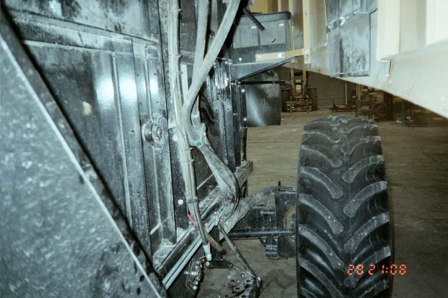
18 INSTALLATION OF DRAIN HOSE FROM RESERVOIR TO VALVE Route supplied 149 drain hose on RH side of machine as shown in above figures and below pictures. Torque to ft.lbs. Use supplied tie straps to secure hose to frame P1 10 Tie Strap Hose Assembly, Drain, Tank-ETII Connect 45 end of drain hose here

19 Connect straight end of drain hose here SETTING TOE-IN Install the new tire and wheel assemblies and torque lug nuts to 442 ft.lbs Lug Nut M20 With rear of combine on blocks and steering wheels straight ahead, check steering wheel toe-in by placing a mark at the center of tread at the rear of each tire at the same distance from the ground as the center of the wheel hub. Measure the distance, X, between these two marks. Rotate tires by hand until the two marks are at the same height from the ground at the front of the tires and measure the distance, Y, between the two marks. Dimension, X, minus dimension, Y, should be 1/4-3/8", when measured at tire outside diameter. To adjust toe-in, loosen jam nuts on steering tie rods and revolve tie rod to make rod length longer or shorter as required to obtain correct toe-in. Attempt to maintain the same amount of exposed threads outside the tie rod on both ends of each tie rod and the same amount on both tie rods. Tighten jam nuts on steering tie rod securely. Torque to ft.lbs. Remove blocks from under combine.

20 ELECTRICAL INSTALLATION In cab, on right console, remove a blank beside feed reversing switch. Remove a connection from bottom of blank and fully install the supplied rocker switch. Slide switch into its position. For older models, connect supplied 147" wire to green wire from combine wiring harness on left side. On combine model 9690 or 660 route wire with and tie to pump drive lube line and then to high pressure hoses. On combine model 9790 or 670, route wire with and tie to high pressure lines. Connect other end of wire to Equa-Trac II solenoid valve. For 2009 and later model year 9795 machines, use provided 48 wire and connect to combine wiring harness on left side that has a 2-way connector with a light-green wire labeled There should be a mating blank connector installed already. Remove blank connector and insert wire terminal from supplied harness into cavity A. This should connect to the green wire, not the black ground wire when re-installing the connector to the harness on the machine. Connect ring terminal to Equa-Trac II valve P1 10 Tie Strap Wire Harness - 147" Wire Harness Rocker Switch PRE-START PROCEDURES Check that all bolts, nuts and hydraulic connections are torqued to specification. Check that all hoses and wires are properly routed, free and clear of moving parts and suitably secured. Check wiring. Turn ignition "ON". Do NOT start engine. Operate rear axle rocker switch "ON" and "OFF". Listen for a soft clicking sound at the valve solenoid to insure proper wiring function. Add hydraulic transmission fluid, as required, to fill hydrostatic reservoir. Follow combine's specifications and recommendations concerning hydrostatic fluid and the servicing of filters. SEE START-UP PROCEDURE AT END OF TROUBLESHOOTING MANUAL.
21 SERVICE PART BREAKDOWNS FROM ASSEMBLIES Swivel Wheel Drive Assy 1250cc Service Part Breakdown P1 2 Adapter, 12 ORB-M X 08 JIC-M P1 1 Adapter, 08 ORB-M X 06 JIC-M Wheel Motor 1250cc C-Frame, Machined Wheel Motor service part breakdown is shown at end of manual P P
22 VALVE BASE ASSEMBLY (SERVICE PARTS ONLY) Item QtyPer Part Number Description P1 90 ELBOW (08 JIC-FS x 08 JIC-M) P1 SWIVEL RUN TEE (08 JIC-FS x 08 JIC-M x 08 JIC-M) P1 ADAPTER (06 ORB-M x 08 JIC-M) P1 ADAPTER (12 ORB-M x 08 JIC-M) HEX SOCKET PLUG (1/4 ORB-M) M1 ADAPTER (12 ORB-M x 04 ORB-F) SOLENOID CARTRIDGE VALVE SOLENOID COIL P1 ADAPTER (04 ORB-M x 04 JIC-M) TUBE ASSEMBLY, PILOT PRESSURE TEE (04 ORB-M x 04 JIC-M x 04 JIC-M) P1 CAP (04 JIC-F) NI SEAL KIT - ET-II (ORB O-RINGS) NI = NOT ILLUSTRATED
23 (1250cc w/swivel) WHEEL MOTOR SERVICE PARTS ITEM # QTY. PART# DESCRIPTION Cylinder Block Assembly Piston Kit Piston Retainer Kit Cam Ring plus O-Rings O-Ring - Cam Ring Distributor Valve Distributor Seal Kit Spring Cover Plate Snap Ring O-Ring Bearing Support Shaft Seal (Inner) Bearing (Outer) Bearing (Inner) Shim Pack Split Retainer Ring Snap Ring Deflector & Grease Seal Bearing Spacer Spacer Back Housing Shim Socket Head Cap Screw M12x P1 Grease Zerk Shaft, Wheel Hub Stud - M Safety Pin Pin (Top) Pin (Bottom) Socket Head Cap Screw M10x Bushing Thrust Washer Seal Cover, Protector Socket Head Cap Screw M6x Outer Pipe Assembly with Seals Inner Pipe Assembly with Seals Seal (Top Pin) Environmental Seal O-Ring, Outer Pipe Back-up Ring Outer Pipe O-Ring, Inner Pipe Back-up Ring Inner Pipe NI Lug Nut, M20 Items 27, 48, 67, 72, 75, 78 are available in Seal Kit. Items 408, 409, 414, 417 are available in K King Pin Bearing Kit. Items 408, 409, 410, 414, 417 are available in King Pin Bearing Kit. Items 418, 419 are provided with item 412. Items 420, 421 are provided with item 413. See illustration on following page (NI=not illustrated).
24
25 4WD Mud Hog Vinyl Decal Application Instructions To apply your decal, please follow the instructions below: 1. Clean area above rear wheel on ladder side of machine to remove dirt and grime. 2. Without removing the paper backing, position decal on surface exactly where you want it. 3. Once the decal is in position, place a piece of masking tape along the top edge to hold the decal in place. 4. The decal should be sitting on the surface like a flap. Lift up the decal and remove the paper backing. 5. With the backing paper completely removed from the decal & transfer tape, gently lower the decal with the transfer tape back down to the surface and rub it down lightly with your hand. 6. The transfer tape should still be on the side of the decal facing you. This allows you to rub the decal without scratching or damaging the decal. Take a squeegee or credit card and firmly rub the transfer tape and thus the decal until it is firmly adhered to the surface. 7. Finally, peel off the transfer tape and masking tape gently. The decal will adhere to the surface much more aggressively than the transfer tape. The transfer tape should lift easily leaving behind no sticky residue. 8. Your decal installation is complete. If there are bubbles present under the decal that cannot be removed by working them to edge, a small needle or pin can be used to puncture the bubble and remove the air. A small pin hole will not be seen after the air bubble has been worked out.
26 LIMITED WARRANTY Tuthill Drive Systems ( Tuthill ) warrants Mud Hog drive systems and components to be free from defects in material and workmanship under normal use and service as shown in the chart below from the date of shipment from Tuthill. Installed By: Warranty Period Tuthill Drive Systems Mud Hog 24 months parts and 12 months labor for the Mud Hog kit & Installation. Authorized Mud Hog Dealer 24 months parts and 12 months labor for the Mud Hog kit. Note: Any defects resulting from installation errors are covered by the installer. Warranty period start date is determined by ship date from Tuthill Drive Systems. Normal use and service means that the product will be installed by a qualified mechanic, operated, inspected and maintained in accordance with the applicable Mud Hog manual or instructions and any applicable vehicle manufacturer s manual or instructions. Tuthill is not liable for any printing errors contained within manuals. THE ABOVE WARRANTY IS EXCLUSIVE. TUTHILL MAKES NO OTHER REPRESENTATIONS OR WARRANTIES, EXPRESS OR IMPLIED, INCLUDING BUT NOT LIMITED TO ANY IMPLIED WARRANTY OF MERCHANTABILITY OR FITNESS FOR ANY PARTICULAR PURPOSE. No agent, distributor, dealer or employee of Tuthill has authority to extend the scope of this warranty. This warranty applies only to products which are sold and used only in the United States, Canada and Mexico. [Tuthill does not itself warrant components which bear the name or trademark of another manufacturer. Any warranty or remedy for such parts is limited to the extent of any warranty provided by the manufacturer to Tuthill.] No warranty applies in the event of replacement of parts with parts not obtained from or approved by Tuthill which do not meet Tuthill quality and performance specifications, improper installation, maintenance, repair, misuse or abuse, or unauthorized alteration or modification. Wheel motor warranty will be denied if the motor is disassembled and or serviced by anyone other than an authorized Tuthill service center within the warranty period. Tuthill reserves the right to make changes and improvements in design, specifications or instructions without notice and without obligation to provide or to substitute new design modifications for those Mud Hog systems or components already in service. Tuthill will at its option refund the purchase price of, or repair or replace without charge for parts, any Mud Hog product determined by Tuthill to be defective in material or workmanship during the applicable warranty period. Labor allowance, if applicable, will be determined in accordance with Tuthill s warranty labor rate and time allowances established from time to time. These remedies are exclusive. In no event shall Tuthill s liability exceed the purchase price for the Mud Hog product when sold by Tuthill to the first buyer. Tuthill shall not be liable for any incidental or consequential damage or expense resulting from any product defect, including but not limited to loss of profits, loss of use of equipment, increased costs or other expenses. This warranty shall become effective only when the Warranty Certificate has been returned to Tuthill and validated by same. INSTALLER AND OWNER RESPONSIBILITIES The installer is responsible for installing the product according to Tuthill s approved procedures, for providing a copy of Tuthill s warranty and installation/parts manual to the owner, and for advising the owner of proper use, service, and maintenance required for the product. The owner is responsible for operation, inspecting and maintaining the product according to the instructions in the installation/parts manual and any applicable vehicle manufacturer s owner s manual, and for properly instructing all operators and maintenance personnel. ADJUSTMENTS When adjustment is sought under this warranty, a claim should be made as follows: A. Tuthill must be notified in writing promptly upon discovery of a claimed defect. B. If the product was installed by the vehicle manufacturer (or it s dealer), follow the manufacturer s procedures for warranty claims; or If the product was purchased from Tuthill through a distributor of Mud Hog products, have the distributor write or phone the Tuthill Customer Service Department and ask for a Returned Goods Authorization Number (RGA#). A warranty claim form will be submitted with information including: The RGA#, Tuthill axle serial #, retail sales date, machine hours and a description of the failure. C. Components requested by Tuthill must be returned freight prepaid and accompanied by a properly completed warranty claim form. Tuthill will specify the ship-to address at time of return approval W. 800 S., Brookston, IN 47923, Tel: / Fax: tdswebinquiries@tuthill.com Web:
JOHN DEERE 9970 COTTON PICKERS
 PARTS CATALOG FOR Mud Hog System II Rear Wheel Drive FOR JOHN DEERE 9970 COTTON PICKERS Mud Hog Model Numbers Tread Center OEM Aftermarket JD40005 JD47655 82, 90, 94, 106 TUTHILL Drive Systems 9098 West
INSTALLATION MANUAL. CNH 5088, 6088, 7088 and 5130, 6130, 7130
 INSTALLATION MANUAL FOR Mud Hog Rear Wheel Drive FOR CNH 5088, 6088, 7088 and 5130, 6130, 7130 COMBINES Mud Hog Model Number: CNH42005 A Product of Tuthill Drive Systems P.O. Box 600 Brookston, Indiana
PARTS CATALOG FOR. Mud Hog Rear Wheel Drive FOR. MF 9540/9550/9560, CAT 540C/550C/560C, Gleaner A540/A560, Fendt 6450R/9480R COMBINES
 PARTS CATALOG FOR Mud Hog Rear Wheel Drive FOR MF 9540/9550/9560, CAT 540C/550C/560C, Gleaner A540/A560, Fendt 6450R/9480R COMBINES Mud Hog Model Number: AG9896 A Product of Tuthill Drive Systems P.O.
PARTS CATALOG FOR. Mud Hog System II & System III 2-Speed Rear Wheel Drive FOR JOHN DEERE 9960, 9965 & 9970 COTTON PICKERS
 PARTS CATALOG FOR Mud Hog System II & System III 2-Speed Rear Wheel Drive FOR JOHN DEERE 9960, 9965 & 9970 COTTON PICKERS Mud Hog Model Numbers Tread Center MH System 9960 9965 & 9970 JD47601 JD47651 82-90
INSTALLATION MANUAL FOR. Mud Hog Front Wheel Drive FOR JOHN DEERE 4-WHEEL 6500 & 6600 SPRAYERS. Mud Hog Model Numbers: JD65004 JD66004 TUTHILL
 INSTALLATION MANUAL FOR Mud Hog Front Wheel Drive FOR JOHN DEERE 4-WHEEL 6500 & 6600 SPRAYERS Mud Hog Model Numbers: JD65004 JD66004 TUTHILL Drive Systems Brookston Indiana USA Revised 8/2010 P.N. 105849
INSTALLATION MANUAL FOR. Mud Hog System II & System III 2-Speed Rear Wheel Drive FOR JOHN DEERE 9960, 9965 & 9970 COTTON PICKERS
 INSTALLATION MANUAL FOR Mud Hog System II & System III 2-Speed Rear Wheel Drive FOR JOHN DEERE 9960, 9965 & 9970 COTTON PICKERS Mud Hog Model Numbers Tread Center MH System 9960 9965 & 9970 JD47601 JD47651
CASE INTERNATIONAL 2055, 2155, 2555 COTTON PICKERS
 INSTALLATION MANUAL FOR Mud Hog System II & System III 2-Speed Rear Wheel Drive FOR CASE INTERNATIONAL 2055, 2155, 2555 COTTON PICKERS Mud Hog Model Numbers Specifications MH System CI49552 102-110 TC
INSTALLATION MANUAL MUD HOG REAR WHEEL DRIVE
 INSTALLATION MANUAL MUD HOG REAR WHEEL DRIVE For Case IH AF 7230, 8230, 9230 Combines TUTHILL DRIVE SYSTEMS MODEL NUMBERS: CNH14023 DUAL SPEED KIT FOR CASE IH AF 7230, 8230, 9230 COMBINES D106483 CNH 84378753
INSTALLATION MANUAL INCLUDING SERVICE PART INFORMATION FOR. Mud Hog System III & System IV 2-Speed Rear Wheel Drive FOR
 INSTALLATION MANUAL INCLUDING SERVICE PART INFORMATION FOR Mud Hog System III & System IV 2-Speed Rear Wheel Drive FOR JOHN DEERE 9560, 9650, 9660 9750, 9760, 9860 STS COMBINES Mud Hog Model Numbers: JD38453
INSTALLATION MANUAL FOR. Mud Hog System II, System III & System IV Rear Wheel Drive
 INSTALLATION MANUAL FOR Mud Hog System II, System III & System IV Rear Wheel Drive FOR Case International 2144, 2166, 2188, 2344, 2366, 2388 COMBINES Mud Hog Model CASE COMBINES For all machines CI21462
For New Holland CR 920/940/960/970/980/9040/9060/9080 CX 720/740/760/780/820/840/860/880/8030/8040/8050/8060/8070/8080/8090
 PARTS CATALOG MUD HOG REAR WHEEL DRIVE For New Holland CR 920/940/960/970/980/9040/9060/9080 CX 720/740/760/780/820/840/860/880/8030/8040/8050/8060/8070/8080/8090 TUTHILL DRIVE SYSTEMS MODEL NUMBERS: CNH4005
PARTS CATALOG MUD HOG REAR WHEEL DRIVE
 PARTS CATALOG MUD HOG REAR WHEEL DRIVE For Case IH AF 7230, 8230, 9230 Combines TUTHILL DRIVE SYSTEMS MODEL NUMBERS: CNH14023 DUAL SPEED KIT FOR CASE IH AF 7230, 8230, 9230 COMBINES A Product of Tuthill
ATV TRACK KIT. Operator s Manual Installation Instructions Service Instructions Replacement Parts List. Effective Date: October, 2012
 p/n 2258-642 ATV TRACK KIT Operator s Manual Installation Instructions Service Instructions Replacement Parts List Track Assembly Kits (p/n 1436-204) Mounting Assembly Kits (p/n 1436-205) 1436-815) Effective
203 TRANSFER CASE CONVERSION
 203 TRANSFER CASE CONVERSION PN:501 OUR FOUR TRANSFER CASE WEDGES REPLACE THE SPIDER GEARS AND CONNECT THE PLANETARY GEAR AND REAR OUTPUT SHAFT MAKING ONE UNIT. SIMILAR IN DESIGN & FUNCTION TO THE BEST
OWNER S GUIDE 8A DURALIFT II 13,200 LB. CAPACITY. Link Mfg. Ltd th St. N.E. Sioux Center, IA USA
 OWNER S GUIDE 8A000715 DURALIFT II 13,200 LB. CAPACITY Link Mfg. Ltd. 223 15th St. N.E. Sioux Center, IA USA 51250-2120 www.linkmfg.com QUESTIONS? CALL CUSTOMER SERVICE 1-800-222-6283 DEALER / INSTALLER:
FRONT DRIVELINE MODIFICATION MAY BE NECESSARY!!!!
 INSTALLATION INSTRUCTIONS FOR 2009 DODGE 2500/3500 4WD & 1500 Mega Cab 6 SUSPENSION SYSTEM PART NUMBER 7206 Requires the following parts (sold separately) for a complete installation: Front Coil Spring
900 SERIES SPLIT CASE FIRE PUMP REPAIR PARTS INDEX
 900 SERIES SPLIT CASE FIRE PUMP REPAIR PARTS INDEX Read and understand the pump and motor instructions before attempting to install, disassemble or repair the pump. Part # AF-03-326 2015 Pentair Ltd. 01/30/15
Installation manual. Toyota Tundra 4WD & 2WD. 2.5 Suspension kit. Part # Part # Important customer information:
 Installation manual 2007-2016 Toyota Tundra 4WD & 2WD 2.5 Suspension kit Part # 53070 sj11082011rev.03 Part # 53070 2007-2016 Toyota Tundra 4WD & 2WD 2.5 Suspension kit Part # Description Qty. 53070-01
LIMITED WARRANTY DISCLAIMER OF IMPLIED WARRANTIES & CONSEQUENTIAL DAMAGES
 Published 08/15 LIMITED WARRANTY Bush Hog warrants to the original purchaser of any new Bush Hog equipment, purchased from an authorized Bush Hog dealer, that the equipment be free from defects in material
4200 & 6200 Owner s Manual & Parts Book
 00 & 00 Owner s Manual & Parts Book Purchase Date Serial Number Model Number Tractor Model PN: - Dealer Date --0 Description Page To The Owner & Maintenance Safety Precautions & Torque Specifications Skid
AGCO. Corn Header Manual d HEADSIGHT.COM
 AGCO Corn Header Manual 09020401d HEADSIGHT.COM 574.546.5022 About Headsight Headsight Contact Info Headsight, Inc. 4845 3B Road Bremen, IN 46506 Phone: 574-546-5022 Fax: 574-546-5760 Email: info@headsight.com
MODEL HD-BTC. Installation, Operation & Repair Parts Information REV041416
 MODEL HD-BTC Installation, Operation & Repair Parts Information REV041416 TABLE OF CONTENTS SAFETY INSTRUCTIONS 1 DEFINITIONS 1 SPECIFICATIONS 2 INSTALLATION INSTRUCTIONS 2 OPERATING INSTRUCTIONS 2 MAINTENANCE
Operator s Manual. Sabre Crop Divider
 Operator s Manual Sabre Crop Divider Canadian Agri Technologies Inc. 47 Halparin Drive Winnipeg, MB. R3X 1Z9 ph. 204 992.2484 fax. 204 237.0552 www.sabredivider.com TOLL FREE PARTS LINE 1 866 792-8437
VALVE AND PLUMBING KIT INSTRUCTIONS SMC 84Q & 2408 LOADERS NEW HOLLAND TRACTORS MODEL 2WD 4WD LESS CAB WITH CAB 1720 X X X 1920 X X X
 ASSEMBLY MANUAL Keep With Operator s Manual VALVE AND PLUMBING KIT INSTRUCTIONS SMC 84Q & 2408 LOADERS NEW HOLLAND TRACTORS MODEL 2WD 4WD LESS CAB WITH CAB 1720 X X X 1920 X X X TRACTOR AND VALVE KIT GENERAL
VALVE AND PLUMBING KIT NEW HOLLAND 7310 LOADER NEW HOLLAND TRACTORS
 ASSEMBLY MANUAL Keep With Operator s Manual VALVE AND PLUMBING KIT NEW HOLLAND 73 LOADER NEW HOLLAND TRACTORS MODEL 2WD FWA LESS CAB WITH CAB TT55 X X X TT75 X X X Valve and plumbing kit can be installed
5) The trailing arm should then pivot smoothly on the chassis. 6) Install the rear bolt. 7) Place one drop of blue Loctite
 The trailing arm should then pivot smoothly on the chassis. 6) Install the rear bolt. 7) Place one drop of blue Loctite") INSTALLATION INSTRUCTIONS 1301 / 1302 / 1305 / 1306 THANK YOU FOR CHOOSING HOTCHKIS PERFORMANCE PRODUCTS Removal of Stock Lower Trailing Arms 1) Place car on level surface. 2) Support rear of the car on
INSTALLATION INSTRUCTIONS 1301 / 1302 / 1305 / 1306 THANK YOU FOR CHOOSING HOTCHKIS PERFORMANCE PRODUCTS Removal of Stock Lower Trailing Arms 1) Place car on level surface. 2) Support rear of the car on
SUPERLIFT Level-It for 2015 GM COLORADO / CANYON INSTALLATION INSTRUCTIONS
 FORM#40028.01-070115 PRINTED IN U.S.A. PAGE 1 OF 6 SUPERLIFT Level-It for 2015 GM COLORADO / CANYON INSTALLATION INSTRUCTIONS INTRODUCTION Installation requires a professional mechanic. The overall vehicle
Installation Instructions
 85-3180 rev. 07 03-14 Installation Instructions Thank you for purchasing this antisway bar kit. Please read through these instructions before installation. Front Anti-Sway Bar Kit for the Ford E350/450
DRAGO. Corn Header Manual f HEADSIGHT.COM
 DRAGO Corn Header Manual 09020801f HEADSIGHT.COM 574.546.5022 About Headsight Headsight Contact Info Headsight, Inc. 4845 3B Road Bremen, IN 46506 Phone: 574-546-5022 Fax: 574-546-5760 Email: info@headsight.com
CAM-LIFT WHEEL MOVE KIT 1500-SERIES S-DRIVE STANDARD CONVEYORS ASSEMBLY MANUAL
 CAM-LIFT WHEEL MOVE KIT ASSEMBLY MANUAL This manual applies to the following models: 1565, 1575, 1585, 1590, 15100 ORIGINAL INSTRUCTIONS Read this manual before using product. Failure to follow instructions
INSTALLATION INSTRUCTIONS FOR MOUNTING HARDWARE KIT F-105K2.5
 MY SAFE T PLUS UNIT INSTALLATION INSTRUCTIONS FOR MOUNTING HARDWARE KIT F-105K2.5 This kit supports installation of SAFE T PLUS : MODEL # 41-140 (RED) MODEL # 41-180 (WHITE) MODEL #41-230 (BLUE) KEEP INSTRUCTIONS
Installation manual Toyota Tundra 4WD & 2WD - 2 front leveling kit Toyota Sequoia 4WD & 2WD - 2 front leveling kit Part # 52070
 Part # 52070 2007-2016 Toyota Tundra 4WD & 2WD 2008-2011 Toyota Sequoia 4WD & 2WD 2 front leveling kit Part # Description Qty. 52070-01 Front strut spacers 2 52070NB Hardware bag 1 52070INST Instruction
Parts Manual E 24 Walk-Behind Scrubber
 Parts Manual E 24 Walk-Behind Scrubber 2 Table Of Contents Chassis Part I...4 Lift Pedal Assembly...6 Chassis Part II...8 Traction Drive...10 Chassis Part III...12 Water Supply Part I...14 Recovery Tank
Installation manual. Rear traction bars. Ram Ram Part # Part # Important customer information:
 Installation manual Rear traction bars Ram 2500 2003-2013 Ram 3500 2003-2012 Part # 30991 sj12062011rev.01 Part # 30991 2003-2013 Ram 2500, 2003-2012 Ram 3500 Rear traction bars Part # Description Qty.
(800) MON-FRI 7AM-5PM PST OR WEBSITE: ReadyLIFT.COM **Please retain this document in your vehicle at all times**
 MON-FRI 7AM-5PM PST OR WEBSITE: ReadyLIFT.COM **Please retain this document in your vehicle at all times**") IF YOUR ReadyLIFT PRODUCT IS MISSING A PART OR HAS A DAMAGED PART, PLEASE CONTACT CUSTOMER SERVICE DIRECTLY. A NEW REPLACEMENT PART WILL BE SENT TO YOU IMMEDIATELY (800)549-4620 MON-FRI 7AM-5PM PST OR
IF YOUR ReadyLIFT PRODUCT IS MISSING A PART OR HAS A DAMAGED PART, PLEASE CONTACT CUSTOMER SERVICE DIRECTLY. A NEW REPLACEMENT PART WILL BE SENT TO YOU IMMEDIATELY (800)549-4620 MON-FRI 7AM-5PM PST OR
PRO JACK 4500 ROLLING BRIDGE JACK 4,500 POUND CAPACITY. PARTS MANUAL P/n NRJ450BK
 PRO JACK 4500 ROLLING BRIDGE JACK 4,500 POUND CAPACITY PARTS MANUAL P/n NRJ450BK 2007 RJ-45 (M) PARTS LIST Item # Part Number Description Qty 1 NRJ45-1000 Bottom Tray 1 2 NRJ45-2100 Outer Scissor 1 3
Read this entire manual before operation begins.
 Read this entire manual before operation begins. Record below the following information which is located on the serial number data plate. Serial No. Model No. Date of Installation Contents Specifications.............
Installation manual. 3.5 suspension system Chevy / GMC 2500HD / 3500HD With contact overloads Part # 13090
 Part # 13090 2011-2016 Chevy / GMC 2500HD / 3500HD With contact overloads 3.5 suspension system Part # Description Qty. 13085-01 DS & PS Upper control arm 2 13085-02 DS & PS Front upper shock bracket 2
Installation manual 2 Leveling kit GM x 4. Part # Part # Important customer information: GM x 4
 Installation manual 2 Leveling kit 2007-2008 GM 1500 4 x 4 Part # 12000 sj121007rev.02 Part # 12000 2007-2008 GM 1500 4 x 4 2 leveling system Parts list: Part # Description Qty. 12000-01 Front leveling
GERINGHOFF. Corn Header Manual f HEADSIGHT.COM
 GERINGHOFF Corn Header Manual 09020701f HEADSIGHT.COM 574.546.5022 About Headsight Headsight Contact Info Headsight, Inc. 4845 3B Road Bremen, IN 46506 Phone: 574-546-5022 Fax: 574-546-5760 Email: info@headsight.com
Installation manual. 3 Suspension Kit Ram WD. Part # Part # Important customer information: 2013 Ram WD
 Installation manual 3 Suspension Kit 2013-2016 Ram 3500 4WD Part # 33118 sj10232013rev.01 Part # 33118 2013 Ram 3500 4WD 3 Suspension Kit Part # Description Qty. 33118-01 Front coil spring spacer 2 33118-02
Technical Support Line: (952) Hanover Ave. Lakeville, MN
 Hanover Ave. Lakeville, MN") Technical Support Line: (952) 985-5675 Email: Sales@QA1.net 21730 Hanover Ave. Lakeville, MN 55044 www.qa1.net INSTALLATION INSTRUCTIONS QA1 1967-1979 Mopar A-Body Rear 6 link Conversion System QA1 p/n
Technical Support Line: (952) 985-5675 Email: Sales@QA1.net 21730 Hanover Ave. Lakeville, MN 55044 www.qa1.net INSTALLATION INSTRUCTIONS QA1 1967-1979 Mopar A-Body Rear 6 link Conversion System QA1 p/n
ASSEMBLY MANUAL. Keep With Operator s Manual
 ASSEMBLY MANUAL Keep With Operator s Manual 2-6347 VALVE AND PLUMBING KIT INSTRUCTIONS SMC 64Q LOADER KUBOTA TRACTORS MODEL 2WD 4WD LESS CAB WITH CAB B2150DT & B2150HSD X X B8200DT & B8200HSD X X B9200DT
J. & M. Mfg. Co., Inc. 284 Railroad Street - P.O. Box 547 Fort Recovery, OH Ph: (419) Fax: (419)
 Fax: (419)") OPERATORS MANUAL Rev.8.14.17 Talc Applicator (Hydraulic) J. & M. Mfg. Co., Inc. 284 Railroad Street - P.O. Box 547 Fort Recovery, OH 45846 Ph: (419) 375-2376 Fax: (419) 375-2708 www.jm-inc.com 2 Table
OPERATORS MANUAL Rev.8.14.17 Talc Applicator (Hydraulic) J. & M. Mfg. Co., Inc. 284 Railroad Street - P.O. Box 547 Fort Recovery, OH 45846 Ph: (419) 375-2376 Fax: (419) 375-2708 www.jm-inc.com 2 Table
AEROMOTIVE Part # / L SOHC Ford Fuel Rail Kit INSTALLATION INSTRUCTIONS
 AEROMOTIVE Part # 14119 98 1/2-04 4.6L SOHC Ford Fuel Rail Kit INSTALLATION INSTRUCTIONS CAUTION: Installation of this product requires detailed knowledge of automotive systems and repair procedures. We
SPECIAL TOOLS REQUIRED:
 INSTALLATION INSTRUCTIONS FOR 2010-15 TOYOTA 4RUNNER WITH XREAS SUSPENSION 3 SUSPENSION LIFT KIT PART NUMBER 432X WARNING!!! READ AND UNDERSTAND ALL INSTRUCTIONS BEFORE PROCEEDING. MAKE SURE THAT YOU HAVE
MODEL EF Full Circle Tire Spreader
 MODEL EF Full Circle Tire Spreader Installation, Operation & Repair Parts Information Branick Industries, Inc. 4245 Main Avenue P.O. Box 1937 Fargo, North Dakota 58103 REV. 062917 P/N: 81-0050C CAUTION
ActuLink ABS Module - ABS-MOD-400
 Installation Instructions ActuLink ABS Module - ABS-MOD-400 For more information on the installation and operation of Tuson s towable ABS system, consult the installation and operations manuals for the
OWNER S MANUAL Z SERIES TRACKS. Rev. 355_05
 OWNER S MANUAL Z SERIES TRACKS Rev. 355_05 LOEGERING 800-373-5441 15514 37 th Street SE 701-347-5441 Casselton, ND 58012 USA Fax: 701-347-4323 E-Mail: lmi@loegering.com Internet: www.loegering.com Loegering
Operation and Parts Manual
 Operation and Parts Manual 3-Point PTO and Hydraulic Stump Grinders Models: SC-25 and SC-25H SC-50 and SC-50H Safety Operation Maintenance Repair Troubleshooting Parts Parts SC-50 and SC-50-H Stumpbuster
Installation Manual. Uniball Upper Control Arm Kit Toyota Tacoma 4x Toyota 4Runner 4x Toyota Tundra 4x4 Part # 50965
 Part # 50965 Uniball upper control arm kit Part # Description Qty. 50965-01 Driver side upper control arm 1 50965-02 Passenger side upper control arm 1 50965-03 Driver side knuckle support bracket 1 50965-04
Installation manual. 2 Suspension System. Ford F150 4WD and 2WD. Part # Part # Ford F150 4WD and 2WD
 Installation manual 2 Suspension System 2009-2018 Ford F150 4WD and 2WD Part # 22929 sj12112013rev.03 Part # 22929 2009-2018 Ford F150 4WD and 2WD 2 Suspension System Part # Description Qty. 22909-01 Front
Rear Sway Bar for XC90 ( ) 2.5T and T6 ipd mounting kit SBK42
 2.5T and T6 ipd mounting kit SBK42") Dedicated to improving vehicle fun, safety & performance Installation Instructions Rear Sway Bar for XC90 (2003-0) 2.5T and T6 ipd mounting kit SBK2 PI-298 08/06 Thank you for purchasing this anti-sway
Dedicated to improving vehicle fun, safety & performance Installation Instructions Rear Sway Bar for XC90 (2003-0) 2.5T and T6 ipd mounting kit SBK2 PI-298 08/06 Thank you for purchasing this anti-sway
Spring-Engaged/Hydraulically-Released BD Caliper Brake. (i) MTY (81) QRO (442) MEX (55)
 MTY (81) QRO (442) MEX (55)") Spring-Engaged/Hydraulically-Released BD Caliper Brake (i) FORM NO. L-07-E-0300 In accordance with Nexen s established policy of constant product improvement, the specifications contained in this manual
Spring-Engaged/Hydraulically-Released BD Caliper Brake (i) FORM NO. L-07-E-0300 In accordance with Nexen s established policy of constant product improvement, the specifications contained in this manual
Prime Attachments & Custom Fab Brush Mower Owners/Operators Manual
 Prime Attachments & Custom Fab Brush Mower Owners/Operators Manual The operator is responsible for the safe operation and maintenance of the machine. It is important that anyone who uses the machine is
Installation Manual Ram x4 4 Lift w/upper control arms. Part # Part # 34105
 Installation Manual 2009 2018 Ram 1500 4x4 4 Lift w/upper control arms Part # 34105 ss09172014 Part # 34105 2009-2018 Ram 1500 4x4 4 suspension system w/upper control arms Part # Description Qty. 34105-01
Instruction set # 7068 Cognito Motorsports, Inc. Upper Control Arm Leveling Kit for GM 8-Lug #UCAK (Boxed Style)
") Cognito Motorsports, Inc. Upper Control Arm Leveling Kit for 2001-2010 GM 8-Lug #UCAK100010 (Boxed Style) Introduction - These control arms will not affect the height of the truck, the height is determined
Cognito Motorsports, Inc. Upper Control Arm Leveling Kit for 2001-2010 GM 8-Lug #UCAK100010 (Boxed Style) Introduction - These control arms will not affect the height of the truck, the height is determined
Dodge SpynTec Hub Conversion Kit
 SpynTec SpynTec Industries Installation Instructions for the Dodge SpynTec Hub Conversion Kit I n d u s t r i e s SpynTec Industries LLC. 11501 South Avenue North Lima, Ohio 4445 1.888.90.AXLE Page 1 Warning
VALVE AND PLUMBING KIT 4211 LOADER CASE IH JX55, JX65, JX75,JX85, AND JX95 TRACKTORS NON-CAB
 ASSEMBLY MANUAL 2-7293 Keep With Operator s Manual VALVE AND PLUMBING KIT 42 LOADER CASE IH JX55, JX65, JX75,JX5, AND JX95 TRACKTORS NON-CAB Valve and plumbing kit can be installed using tools ordinarily
Endlinks Installation Guide v1.0 (Feb 2015) Part No s: EC ; EC ; EC
 Part No s: EC ; EC ; EC") Endlinks Installation Guide v1.0 (Feb 2015) Part No s: EC0202-0306; EC0202-0305; EC0202-0304 Application VW Mk7 Golf, GTI, Golf R Audi 8V A3, S3 List of Parts Included List of Required Tools A. Front End
Endlinks Installation Guide v1.0 (Feb 2015) Part No s: EC0202-0306; EC0202-0305; EC0202-0304 Application VW Mk7 Golf, GTI, Golf R Audi 8V A3, S3 List of Parts Included List of Required Tools A. Front End
VALVE AND PLUMBING KIT 2408TL LOADER AGCO & MASSEY FERGUSON TRACTORS
 ASSEMBLY MANUAL Keep With Operator s Manual VALVE AND PLUMBING KIT 2408TL LOADER AGCO & MASSEY FERGUSON TRACTORS AGCO MASSEY FERGUSON CAB ROPS ST34A 1533 X ST41A 1540 N/A X TRACTOR AND VALVE KIT GENERAL
Installation manual. 1.5 front leveling kit. Nissan Titan. Part # Part # Important customer information: Nissan Titan
 Installation manual 1.5 front leveling kit 2004-2015 Nissan Titan Part # 52008 sj071408rev.01 Part # 52008 2004-2015 Nissan Titan 1.5 front leveling kit Part # Description Qty. 52008-01 Front strut spacers
Hydraulic Transmission Jacks
 Hydraulic Transmission Jacks Operating Instructions & Parts Manual Model Number Atd-7435 Atd-7436 Atd-7437 Capacity 1100 Lb. 2000 Lb. 3000 Lb. Model Atd-7435 Model Atd-7436 Model Atd-7437 Atd Tools Inc.
PARTS LIST. Guardian A- Series. Material Pumps
 PARTS LIST Guardian A- Series Material Pumps Table Of Contents Section 1 General Information 1:1 Assembly Drawings... 3 1:2 Sub Assembly Drawings... 6 1:3 Maintenance... 14 Section 2 Technical & Warranty
PARTS LIST INCLUDED IN KIT TORQUE SPECIFICATIONS PRODUCT SAFETY LABEL MUST BE INSTALLED INSIDE CAB IN PLAIN VIEW OF ALL OCCUPANTS.
 INSTALLATION INSTRUCTIONS FOR 2010-15 TOYOTA 4RUNNER SR5 AND SPORT (Non-Air Leveling & Non-X-REAS) AND FOR 2010-14 TOYOTA FJ CRUISER 2WD & 4WD 3 SUSPENSION LIFT KIT PART NUMBER 432 WARNING!!! READ AND
Model 802 Center Mount Adapter For New Holland 9030 & TV140 Bi-Directional Tractors PARTS CATALOG
 Model 802 Center Mount Adapter For New Holland 9030 & TV140 Bi-Directional Tractors 1 PARTS CATALOG TABLE OF CONTENTS Frame & Tractor Linkage...2,3 Header Linkage & Float Group...4,5 Header Drive Hydraulics
PREMIER, MARINE, & STANDARD
 INSTA LLATION INSTRUCTION AND SERVICE MANUAL I TITAN 12" x 2" BRAKES FREE BACKING. UNI-SERVO. DUO-SERVO PREMIER, MARINE, & STANDARD Limited Warranty TITAN Inc. ("TITAN') warrants its products to be free
Installation manual. Rear ladder bars. Chevy/GMC 2500/3500 HD. Part # Part # Important customer information:
 Installation manual 2011-2018 Chevy/GMC 2500/3500 HD Part # 10892 sj07272011rev.01 Part # 10892 2011-2018 Chevy/GMC 2500/3500 HD Part # Description Qty. 10892-01 Rear ladder bar brackets 2 10892-02 Front
Installation manual. 4.5 suspension system June 2007 Dodge Ram 2500 / Part # Part # Important customer information:
 Installation manual 4.5 suspension system 2003 - June 2007 Dodge Ram 2500 / 3500 Part # 34003 sj11407rev.03 Part # 34003 2003 - June 2007 Dodge Ram 2500 / 3500 4.5 suspension system Part # Description
AEROMOTIVE Part # Subaru Fuel Rails for Top Feed Injectors WRX & STI INSTALLATION INSTRUCTIONS
 AEROMOTIVE Part # 14135 Subaru Fuel Rails for Top Feed Injectors 02-14 WRX & 07-14 STI INSTALLATION INSTRUCTIONS CAUTION: Installation of this product requires detailed knowledge of automotive systems
Owner s Manual TC-515 with Reversed Hoist, Sub-Frame, Deck, & Hitch Mount
 Proudly built in the USA Owner s Manual TC-55 with Reversed Hoist, Sub-Frame, Deck, & Hitch Mount TruckCraft Corporation Chambersburg, PA -800-755-87 Copyright c 0 www.truckcraft.com TruckCraft Corporation
AGCO Conversion Manual a HEADSIGHT.COM
 AGCO 3300 Conversion Manual 09040404a HEADSIGHT.COM 574.546.5022 About Headsight Headsight Contact Info Headsight, Inc. 4845 3B Road Bremen, IN 46506 Phone: 574-546-5022 Fax: 574-546-5760 Email: info@headsight.com
Power Float Manifold. Installation and Operations Manual Module 11A
 Power Float Manifold Installation and Operations Manual Module 11A 2/14 Table of Contents 1 Features 3 2 Functional Purpose 3 3 4 Specifications System Installation 3 4 4.1 Hydraulic Connection 4 4.2 Electric
Operating Instructions and Parts Manual Long Chassis Service Jacks
 Operating Instructions and Parts Manual Long Chassis Service Jacks Models JSJ-3T/JSJ-5T/JSJ-10T WMH TOOL GROUP 2420 Vantage Drive Elgin, Illinois 60123 Part No. M-454430 Ph.: 800-274-6848 Revision A 8/05
Read this entire manual before operation begins.
 Read this entire manual before operation begins. Record below the following information which is located on the serial number data plate. Serial No. Model No. Date of Installation Contents Specifications.............
MOVE ON TO THE REAR BAR INSTALLATION
 22410 STREET SWAY BAR SET 2001-UP LEXUS IS300 Thank you for your purchase from our line of Lexus parts. Please call us at (877) 4NO-ROLL if you have any questions regarding the service or installation
Post Driver Attachment
 Attachment (Shown with Optional Power Cell Rotator) Models - 600, 850 Safety Instructions This safety alert symbol indicates important safety messages in this manual. When you see this symbol, carefully
HINO PTO INTERFACE PTO INSTALLATION AND OPERATOR S MANUAL KEEP IN VEHICLE. FOR Allison 2500 With CS6B-A67**-S3*H PTO
 KEEP IN VEHICLE READ OPERATING INSTRUCTIONS INSIDE BEFORE OPERATING PTO HINO PTO INTERFACE PTO INSTALLATION AND OPERATOR S MANUAL FOR Allison 2500 With CS6B-A67**-S3*H PTO Muncie Power Products, Inc. Important
Cognito Motorsports, Inc. Upper Control Arm Kit for 2011-Present GM 8-Lug #UCAK100051
 Cognito Motorsports, Inc. Upper Control Arm Kit for 2011-Present GM 8-Lug #UCAK100051 Introduction - Installation requires a qualified mechanic. - Read instructions carefully and study the pictures (if
Installation Manual. Upper Control Arms W/Uniball joint Toyota Tacoma 4wd & 2wd PreRunner. Part # Part # 50930
 Installation Manual Upper Control Arms W/Uniball joint 2005-2016 Toyota Tacoma 4wd & 2wd PreRunner Part # 50930 SS08182014 Part # 50930 Upper Control Arms W/Uniball joint 2005-2016 Toyota Tacoma 4wd &
MODEL 7400 STRUT SPRING COMPRESSOR
 MODEL 7400 STRUT SPRING COMPRESSOR Installation, Operation & Repair Parts Information Branick Industries, Inc. 4245 Main Avenue P.O. Box 1937 Fargo, North Dakota 58103 REV112712 P/N: 81-0103A TABLE OF
AEROMOTIVE Part # L 4V Fuel Rails INSTALLATION INSTRUCTIONS
 AEROMOTIVE Part # 14130 5.0L 4V Fuel Rails INSTALLATION INSTRUCTIONS CAUTION: Installation of this product requires detailed knowledge of automotive systems and repair procedures. We recommend that this
Automated Lubrication System
 Automated Lubrication System Installation/Operation Manual Case IH Combine Models 2344, 2366, 2377 and 2388 Revised 08-09-06 1 System Overview Thank you for purchasing the Quicklub On Board Grease System
Operating Manual High Viscosity Dispense Valve Item #
 Operating Manual High Viscosity Dispense Valve Item # 984594 CLOSE OPEN Item # 984594 Label # 8901197 Warnings INJECTION HAZARD Spray from the valve, hose leaks, or ruptured components can inject fluid
INSTALLATION INSTRUCTIONS FOR FORD 4WD SUPER DUTY F /2 COIL SPRING SUSPENSION SYSTEM
 INSTALLATION INSTRUCTIONS FOR 2005-07 FORD 4WD SUPER DUTY F250-350 4 1/2 COIL SPRING SUSPENSION SYSTEM Requires the following parts (sold separately) for a complete installation: KIT PART NUMBER (6345
OWNER S MANUAL. LOEGERING th Street SE Casselton, ND USA Fax:
 OWNER S MANUAL TRAIL BLAZERS and D SERIES TRACKS LOEGERING 800-373-5441 15514 37 th Street SE 701-347-5441 Casselton, ND 58012 USA Fax: 701-347-4323 E-Mail: lmi@loegering.com Internet: www.loegering.com
INSTALLATION MANUAL TOYOTA TUNDRA 5 SUSPENSION SYSTEM PART # 55905
 PART NUMBER : 55905 1999 2003 TOYOTA TUNDRA 5 SUSPENSION SYSTEM PARTS LIST: Part # Description Qty. 55900-01 Driver Side Spindle 1 55900-02 Passenger Side Spindle 1 55905-03 Rear brake proportioning valve
Cardinal DETECTO. PORTABLE PLATFORM SCALES Digital Type Series 850F Owner s Manual
 Cardinal DETECTO PORTABLE PLATFORM SCALES Digital Type Series 850F Owner s Manual CARDINAL SCALE MFG. CO. PO BOX 151, WEBB CITY, MO 64870 0066-M176-O1 Rev H 10/06 417-673-4631 www.cardinalscale.com Printed
AEROMOTIVE Part # Ford 5.4L GT500 Shelby Mustang Fuel Rail Kit INSTALLATION INSTRUCTIONS
 AEROMOTIVE Part # 14145 07 Ford 5.4L GT500 Shelby Mustang Fuel Rail Kit INSTALLATION INSTRUCTIONS CAUTION: Installation of this product requires detailed knowledge of automotive systems and repair procedures.
CORN HEADER MANUAL: CNH PRE-2012
 CORN HEADER MANUAL: CNH PRE-2012 09020201c HEADSIGHT.COM 574.546.5022 About Headsight Headsight Contact Info Headsight, Inc. 4845 3B Road Bremen, IN 46506 Phone: 574-546-5022 Fax: 574-546-5760 Email:
Installation Instructions
 Nov 25, 2013 Upper Control Arms Installation Instructions The following instructions are intended for professional installers and are guidelines only. Speedtech Performance assumes NO responsibility for
PARTS LIST FOR SKU: (UCAK100051)
") INSTALL INSTRUCTIONS: Cognito Upper Control Arm Kit for 2011-2018 GM 2500HD / 3500HD 2WD / 4WD trucks. (Ball Joint Style Boxed) New SKU: 110-90298 PARTS LIST FOR SKU: 110-90298 (UCAK100051) QUANTITY PART
INSTALL INSTRUCTIONS: Cognito Upper Control Arm Kit for 2011-2018 GM 2500HD / 3500HD 2WD / 4WD trucks. (Ball Joint Style Boxed) New SKU: 110-90298 PARTS LIST FOR SKU: 110-90298 (UCAK100051) QUANTITY PART
TITAN 13 x 2½ BRAKES DUO-SERVO AND FREE BACKING
 INSTALLATION INSTRUCTION AND SERVICE MANUAL Actuator/Trailer Dealer - Please provide these instructions to the consumer. Consumer - Read and follow these instructions. Keep them with the trailer for future
INSTALLATION INSTRUCTIONS FOR FORD 4WD SUPER DUTY 2-1/2 SUSPENSION SYSTEM
 INSTALLATION INSTRUCTIONS FOR 1999-2004 FORD 4WD SUPER DUTY 2-1/2 SUSPENSION SYSTEM Requires the following parts for a complete installation: Front Leaf Springs P/N 60SD25 Vehicle specific Box Kit depending
BX7322 Adventurer Tow Bar Operator Manual & Installation Instructions
 Please visit www.blueox.com for the latest version of these installation instructions. BX7322 Operator Manual & Installation Instructions Serial Number (5,000 lb) 2 Inch Coupler 292-1263 Rev J Page 1 of
DeZURIK 2 20" BOS BUTTERFLY VALVES
 2 20" BOS BUTTERFLY VALVES Instruction D10459 October 2013 2-20 BOS Butterfly Valves Instructions These instructions provide information about BOS Butterfly Valves. They are for use by personnel who are
Heavy Duty Front-Drive Steer Axles MX-140 and MX-160 Series
 Revised 11/2009 Heavy Duty Front-Drive Steer Axles MX-140 and MX-160 Series Catalog PB-0349 Strength Power Speed Agility MERITOR PARTS. RIGHT FROM THE START. TABLE OF CONTENTS MX-17/19/21-140 and MX-21/23-160
HP30 Slab Saw Owner s Manual and Operating Instructions
 HP30 Slab Saw Owner s Manual and Operating Instructions MADE IN USA Revision 07 09.0 Manual Part No. 67 Caution: Read all safety and operating instructions before using this equipment. This manual MUST
04 & 14 F FRONT 1.0 REAR LEVELING KIT INSTALLATION
 INSTRUCTION PART NO 15312 KIT NO 3836 04 & 14 F-150 2.0 FRONT 1.0 REAR LEVELING KIT INSTALLATION READ INSTRUCTIONS COMPLETELY THROUGH BEFORE STARTING. FAILURE TO ADHERE TO THE INSTRUCTIONS WILL VOID ANY
AEROMOTIVE Part # L Ford F L Ford Expedition L Ford F-250 Super Duty INSTALLATION INSTRUCTIONS
 AEROMOTIVE Part # 14118 97-03 5.4L Ford F-150 97-02 5.4L Ford Expedition 98-03 5.4L Ford F-250 Super Duty INSTALLATION INSTRUCTIONS CAUTION: Installation of this product requires detailed knowledge of