Instruction Manual. Wingspan : 1444mm (56.85 inches) : 1195mm (47.05 inches) : two stroke / four stroke. : 4 channel 5 servos
|
|
|
- Barrie Owens
- 6 years ago
- Views:
Transcription


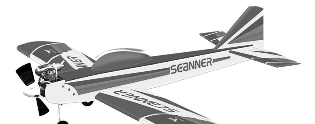


1 ALMOST READY TO FLY Wingspan : 1444mm (56.85 inches) g Length : 1195mm (47.05 inches) Weight : 2400gr Engine : two stroke / four stroke Radio : 4 channel 5 servos We wish you many enjoyable flights with your plane and one again thank you for your choosing a Phoenix Model products.
2 INTRODUCTION Thank you for choosing the new ARF by Phoenix Model. The was designed from the ground up with the intermediate sport flyer in mind. It is a low wing sport aerobatic aircraft that is easy to fly and quick to assemble, yet is capable of aerobatics to please even the best sport pilot. The airframe is conventionally built using balsa, plywood and veneer to make it stronger than the average ARF kit, yet the design allows the aircraft to be built light as well. You will find that most of the work has been done for you already. The pushrods are premade to the correct lengths, the motor mount has been installed and even the hinges are preinstalled and pinned for security. Flying the is simply a joy too. It's constant cord wings make landing a breeze without the bad habits of other aerobatic planes and it's generous stabilizer area keeps it tracking straight and true. The ARF is an easy flying sport airplane, however, it may not be appropriate for some first time modelers. If you have chosen the ARF as your first airplane, we recommend you seek assistance from an experienced modeler. We know you'll enjoy flying the ARF as much as we have enjoyed designing it for you. We encourage you to let us know about your successes. Fill out the consumer feedback survey at the end of the manual, send us a letter or contact us on the Internet. Again, thank you for purchasing the ARF by Phoenix Model. ADDITIONAL ITEMS REQUIRED Two Stroke Engine 4 Channel Radio With 4 Servos Glow Plug to Suit Engine Propeller to suit Engine Dubro Protective Foam Rubber Global Silicon Fuel Line Prather Stick On Weight For Balance TOOLS AND SUPPLIES NEEDED Kwik Bond #2 Thick C/A Glue Kwik Bond 30 Minute Epoxy Kwik Bond 5 Minute Epoxy Hand or Electric Drill Assorted Drill Bits Modeling Knife Straight Edge Ruler 2mm Bondhus Ball Driver #
3 KIT CONTENTS: We have organized the parts as they come out of the box for better identification during assembly. We recommend that you regroup the parts in the same manner. This will ensure you have all of parts required before you begin assembly. KIT CONTENTS AIR FRAME ASSEMBLIES AILERON CONTROL SYSTEM (2) Wing halves with ailerons (1) Fuselage with canopy. (1) Horizontal stabilizer with elevator halves (1) Vertical stabilizer with rudder (1) Instruction manual (2) 1.7mm x 180mm metal pushrod (2) Nylon clevises (2) Silicon tube (2) Nylon snap keeper (2) Nylon control horn (8) 2mm x 10mm wood screws MAIN GEAR ASSEMBLY (4) 2mm x 16mm wood screws (2) Main gear (2) 65mm diameter wheels (4) Wheel collars (4) 3mm x 4mm machine screws (4) Nylon plate (8) 3mm x 12mm wood screws MOTOR MOUNT ASSEMBLY (4) 3mm x 20mm wood screws (4) Lock washer FUEL TANK NOSE GEAR ASSEMBLY (1) Nylon fuel Tank (1) Metal clunk (1) Pre - assembled stopper w / 2 tube (1) Nose gear (1) 65mm diameter wheel (2) Wheel collar (2) 3mm x 4mm machine screw (1) Nylon Steering arm MISCELLANEOUS ITEMS (1) Aluminum dihedral (2) Wing screws (2) 4mm x 30mm nylon screws (2) Metal connector (2) 1.7mm x 700mm metal pushrod (2) Nylon bushing (1) Spinner (1) 25mm x 600mm trim tape (white) ELEVATOR CONTROL SYSTEM (1) Nylon clevises (1) Silicon tube (1) Nylon snap keeper (2) 2mm x 16mm screws (1) Nylon control horn w/plate ADDITIONAL ITEMS REQUIRED RUDDER CONTROL SYSTEM 40 two stroke Engine. 4 channel Radio with 4 servos. Glow plug to suit Engine. Propeller to suit Engine. Protective foam Rubber. Silicone fuel line. Stick on weight for balance. (1) Nylon clevises (1) Silicon tube (1) Nylon snap keeper (2) 2mm x 16mm screws (1) Nylon control horn w/plate 2
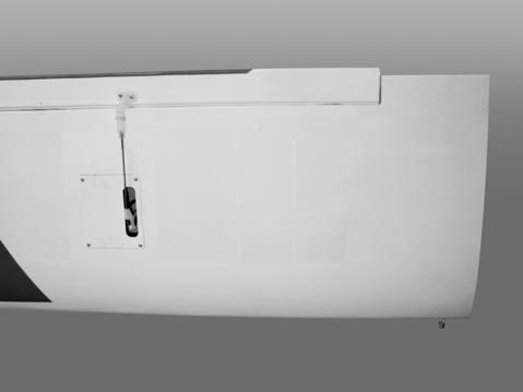
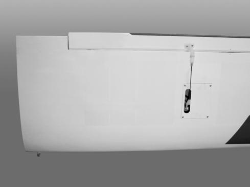
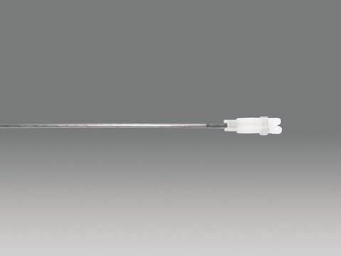
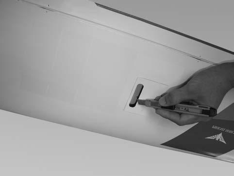
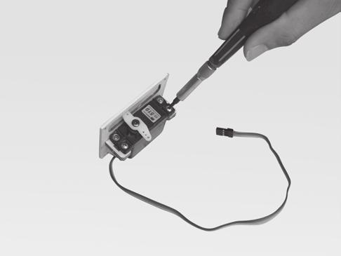
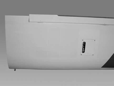
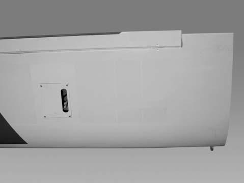
4 **SUGGESTION** to avoid scratching your new airplane, do not unwrap the pieces until they are needed for assembly. Cover your workbench with an old towel or brown paper, both to protect the aircraft and to protect the table. Keep a couple of jars or bowls handy to hold the small parts after you open the bags. **NOTE** Please trial fit all the parts. Make sure you have the correct parts and that they fit and are aligned properly before gluing! This will assure proper assembly. Since the ARF is hand made from natural materials, every plane is unique and minor adjustments may have to be made. However, you should find the fit superior and assembly simple. **WARNING** The paint and plastic parts used in this kit are fuel proof,however they are not tolerant of many harsh chemicals including the following: Paint thinner, C/A Glue Accelerator, C/A Glue Debonder and Acetone. Do not let these chemicals come in contact with the colors on the covering and the plastic parts. Installing The Aileron Servos 4. Using the thread as a guide and using masking tape, tape the servo lead to the end of the thread: carefully pull the thread out. When you have pulled the servo lead out, remove the masking tape and the servo lead from the thread. 1. Install the rubber grommets and brass eyelets onto the aileron servo. 2. Using a modeling knife, remove the covering from over the pre-cut servo arm exit hole on the aileron servo tray / hatch. This hole will allow the servo arm to pass through when installing the aileron pushrods. Servo lead 3 5. Place the aileron servo tray / hatch into the servo box on the bottom of the wing and drill 1,6mm pilot holes through the tray and the servo box for each of the four mounting screws. Secure the servo tray in place using the mounting screws provided ( 2mm x 12mm ). Remove the covering 1 3. Place the servo into the servo tray. Center the servo within the tray and drill 1,6mm pilot holes through the block of wood for each of the four mounting screws provided with the servo. To the cowl 4 6. Repeat step # 2 - # 5 to install the second aileron servo in the opposite wing half. 2 3
5 To the cowl Using masking tape, tape the servo leads on to the top of the wing. 2. Attach the clevis to the outer hole in the control horn. Install a silicone tube on the clevis. Installing The Control Horns 3. Locate one nylon servo arm, and using wire cutters, remove all but one of the arms. Using a 2mm drill bit, enlarge the third hole out from the center of the arm to accommodate the aileron pushrod wire. 1. One aileron control horn in positioned on each aileron. Using a ruler and a pen, locate and mark the location of the control horn. It should be mounted on the bottom side of the aileron at the leading edge, in line with the aileron pushrod. 4. Plug the aileron servo into the receiver and center the servo. Install the servo arm onto the servo. The servo arm should be perpendicular to the servo and point toward the middle of the wing. 2. Drill two 1.6mm holes through the aileron using the control horn as a guide and screw the control horn in place. 5. Center the aileron and hold it in place using a couple of pieces of masking tape. 6. With the aileron and aileron servo centered, carefully place a mark on the aileron pushrod wire where it crosses the hole in the servo arm. 7. Using pliers, carefully make a 90 degree bend down at the mark made. Cut off the excess wire, leaving about 4mm beyond the bend. 8. Insert the 90 degree bend down through the hole in the servo arm. Install one nylon snap keeper over the wire to secure it to the arm. Install the servo arm retaining screw and remove the masking tape from the aileron. 6 RIGHT Silicone Tube WRONG 3. Repeat step # 1 - # 2 to install the control horn on the opposite aileron. To the cowl 8 Installing The Aileron Linkages 9. Repeat step # 4 - # 8 to install the second aileron linkage. After both linkages are completed, connect both of the aileron servo leads using a Y-harness you have purchased separately. 1. Working with the aileron linkage for now, thread one nylon clevis at least 14 turns onto one of the 2mm x 180mm threaded wires. 4
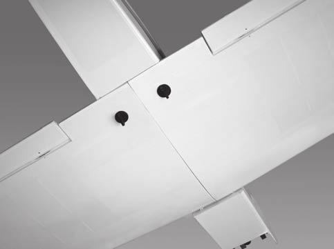
6 2) Test fit the dihedral brace into each wing half. The brace should slide in easily up to the centerline you drew. If it does not, use 220 grit sandpaper with a sanding block and sand down the edges and ends of the brace until the proper fit is obtained. To the cowl *Note* the dihedral brace is cut in the shape of a "V". This shape gives the wing the correct dihedral angle. Make sure you don't test fit the brace upside down. 9 3) When satisfied with the fit of the dihedral brace in each wing half, remove the brace.mix equal amounts of part A and part B 30 minute epoxy. Coat all sides of the dihedral brace box and half of the wing brace with the epoxy. Make sure to cover the top and bottom as well as the sides. Use enough epoxy to fill any gaps. Installing The Wing To The Fuselage Attach the wings to the joiner tube and using the nylon thumbscrews to secure the wing panels to the fuselage. 4) Insert the dihedral brace into one wing half up to the centerline. Wipe off any excess epoxy that may have squeezed out of the joint using paper towels. See photo #2 below Screw Dihedral brace 10 Wing Assembly *Note* We highly recommend using 30 Minute Epoxy over faster curing epoxies for several reasons. First, slower curing epoxy is stronger. It also providers more working time, allowing the builder to properly align the parts. Using fast cure epoxy when joining the wing halves could result in the glue drying before the wing halves are aligned properly, causing damage to the wing assembly. Also, when joining the wing halves, the entire area of both center ribs need to be joined completely with no gaps existing. Not following these steps carefully, may result in failure of the wing center section during flight. 12 5) Once the epoxy has cured, trial fit both wing halves together.the center gribs should fit flush together with little or no gaps existing. If gaps do exist, use 220 Grit sandpaper and sand down the high spots on the root ribs and the wing joiner until the proper fit is obtainer. The amount of dihedral is built into the wings by angling the root ribs the correct amount. With one wing half flat on the table, the other wing tip should be approximately 2" off of the surface of the table. If this need to be adjusted, you may do so by sanding small amount from the center ribs or dihedral brace. 1) Locate the plywood wing dihedral brace. Using a ruler, locate it's center and place a mark. Draw a vertical line at the mark just made. See photo #1 below. 6) To protect the covering from the epoxy used to glue the wing halves together, carefully apply masking tape around the edge of the root rip on the top and bottom of each wing half. See photo #3 below. Make centerline 11 5
7 Glue with epoxy ) Bolt the wing to the fuselage. Set the horizontal stabilizer onto the stabilizer mounting platform on the fuselage. To align the horizontal stabilizer with the wing, use figure #2 and # 3. when viewed from the rear, the horizontal stabilizer should be level with the wing. If it is not level, use sandpaper and sand down the high side of the stabilizer mounting platform until the proper alignment is achieved. Measure the distance form each wing tip to each stabilizer tip. These distances should be equal. If they are not, adjust the stabilizer until the measurements are equal. 7) Mix a generous amount of 30 minute epoxy. Coat the exposed half of the dihedral brace, the wing joiner box and both root ribs with epoxy. Slide the two wing halves together and carefully align them at the leading and trailing edges. Wipe away any excess epoxy using paper towels. Use masking tape wrapped around the center section to hold the halves in place until the epoxy cures. See photo # 4below. FIGURE # 2 A=A-1 A-1 A 14 8) When the epoxy has cured, carefully remove the masking tape from the wing. 9) Peel off the backing from the self adhesive covering strip used to cover the center section wing joint seam. Apply the strip to the center section of the wing on the bottom first, and the top using the rest of the material. A=A-1 FIGURE # 3 90O Horizontal and vertical stabilizer installation A B B=B-1 B1 A1 3) When you are satisfied with the alignment, hold the stabilizer in place with T-pins or masking tape, but do not glue at this time. 1) Using your ruler, find the centerline of the horizontal stabilizer, at the trailing edge, and place a mark. Use a triangle and extend this mark, from back to front, across the top and bottom of the stabilizer. Also place a mark at the centerline of the fuselage at the front and rear of the stabilizer mounting area. These mark will be used to line up the stabilizer to the fuselage. See photo #9 below. 4) On the bottom of the horizontal stabilizer, draw a line where it and the fuselage meet. Do this on both the right and left sides. 6
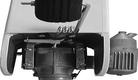
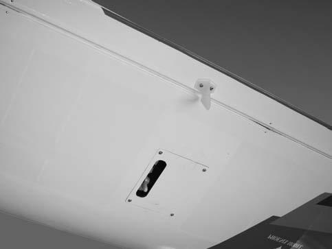
8 2) Remove the muffler from the engine and set the engine in the mount. Adjust the depth of the engine in the mount. The front of the thrust washer should be 5/16'' forward of the front edge of the fuselage sides. This will allow clearance for the propeller. 5) Remove the horizontal stabilizer. Using the lines you just drew as a guide, carefully remove the covering from between them, using a modeling knife. This is where the horizontal stabilizer will be glued in place. 6) When you are sure that every thing is aligned correctly, glue the horizontal stabilizer in place using 30Minute Epoxy. Double check all of your measurements once more before the epoxy cures. Hold the stabilizer in place with T-pins or masking tape until the epoxy has cured. 3) Once satisfied with the fit of the engine, mark the position of the four engine mounting holes onto the mount. Remove the engine and drill out the mounting holes using a 7/64'' drill bit. Drill one hole at a time, checking the alignment after each hole is drilled. 7) Slide the vertical stabilizer into the slot in the mounting platform in the top of the fuselage. Mark the shape of the fuselage on the left and right sides of the vertical stabilizer using a felt-tip pen. 4) When reinstalling the engine into the motor mount, connect the carburetor arm to the preinstalled throttle pushrod. The Z-Bend fits into the lower hole in the throttle arm. Mount the engine using the four3*25mm flat head wood screws. See photo #11 below. 8) Now, remove the vertical stabilizer and using a modeling knife, carefully cut just inside the marked lines and remove the film on both sides of the vertical stabilizer. Just as you did with the horizontal stabilizer, make sure you only press hard enough to cut the film, not the balsa vertical stabilizer. Glue with epoxy 17 5) Mount the muffler to the engine using the mounting bolts provided with your engine. 16 Landing Gear Installation 9) Set the vertical stabilizer back in place. Using a triangle, check to ensure that it is 900 to the horizontal stabilizer. 1) Locate the two main landing gear wires, one nose gear wire, four nylon mounting straps eight 3*12mm Phillips head sheet metal screws, three wheels, six wheel collars w/set screws, and one nylon steering arm with set screw. See photo #12 below. 10) Once you are sure that everything is aligned correctly, glue the vertical stabilizer in place using 30 Minute Epoxy. Double check all of your measurements once more before the epoxy cures. Hold the stabilizer in place with T-pins until the epoxy has cured. Engine Mounting 1) Test fit your engine into the engine mount. Because the width of different engines differ, the motor mount may need to be widened to accommodate your engine. You can do this by loosening the motor mount screw and sliding the mounting beams apart. When satisfied with the fit, tighten the mounting screws. 18 7
9 6) The preinstalled wire steering pushrod has a factory made Z-Bend on the front end of it. Connect the nylon steering arm to this pushrod. The pushrod should be installed in the outermost hole in the steering arm. See figure # 4 below. 2) There are two hardwood landing gear blocks with one precut channel in each block in the bottom of the wing. Locate the two landing gear blocks on the bottom of the wing and using a modeling knife, remove the covering from over the precut channels. See photo #13 below. FIGURE #4 STREERING ARM Remove the covering SET SCREW Z-BEND PUSHROD WIRE 19 7) Locate the nose gear wire. Slide the nose gear wire up through the lower portion of the nose gear block, then through the nylon steering arm, then through the upper portion of the nose gear block. The top of the nose gear wire should be flush with the top of the nose gear bracket. See photo # 15 below. 3) Test fit the two main gear wires into the channels. When satisfied with the fit, secure the wires in place using the four nylon straps and eight 3*12mm sheet metal screws. If you look closely at the wing surface surrounding the channel for the wire, you will notice that there are already four pilot holes drilled to accommodate the screws for the straps. Mount the straps at these locations. See photo # 14 below. Steering arm Wheel Set screw arm Main gear Nose gear arm 21 Nylon plate Coloa 8) With the nose gear wire straight, angle the nylon steering arm about 300 forward of the fire-wall and tighten the set screw. Angling the arm forward like this will allow room for the arm to move back for more adequate steering. Screw 20 4) Install two of the wheels onto the axles using the four wheel collars and set screws provided. The wheels should be centered on the axles with a wheel collar on each side, holding them in place. Tighten the set screws on the collars to secure them in place.the wheels should rotate freely. You should apply a small drop of lock-tite thread lock to each set screw to prevent them from coming loose. 9) Install the remaining wheel onto the axle using the two wheel collars and set screws provided. The wheel should be centered on the axle with a wheel collar on each side, holding it in place. Tighten the set screws on the collars to secure them in place. The wheel should rotate freely. You should apply a small drop of Lock_tite thread lock to each set screw to prevent them from coming loose. 5) Remove the hatch cover from the bottom front of the fuselage. Working with the preinstalled nylon steering housing, position it so the end of it is flush with the front of the firewall. When satisfied with the fit, glue the housing to the firewall from the inside of the fuselage using 5 Minute Epoxy. Fuel Tank Assembly 1) Locate the plastic molded fuel tank, preassembled stopper assembly, weighted pick-up and a length of fuel line about 2-1/2 '' long (not included). For steps # 2-4, refer to photo #16 below. 8
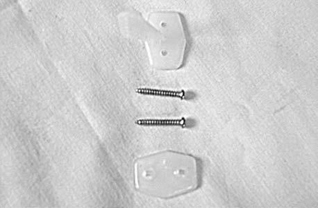
10 Stopper assembly 9) Use pieces of the foam provided to hold the tank in place. Be careful the tank or the foam doesn't interfere with the pushrods. Vent tube Fuel pick-up tube Fuel line 10) Connect the fuel pick-up line to the carburetor fuel inlet nipple and the muffler pressure line to the pressure nipple on your engine's muffler. Clunk 22 Spinner installation 2) Attach the weighted pick-up, more com-momly referred to as the "clunk", to one end of the silicon fuel line. 1) Locate the molded plastic spinner, two 3*12mm Phillips head sheet metal screws and the Propeller to suit your engine (not included). 3) Slide the other end of the silicon fuel line onto the end of one of the tubes coming out of the rear of the stopper assembly. This will be your fuel pickup line. When mounted the clunk should rest 3/8'' from the rear of the tank and should move freely within the tank. The silicon tubing should be trimmed to fit. 2) Most.40 size displacement engines use a 1/4'' diameter crankshaft. You may need to enlarge the hole in the spinner backplate and the propeller to fit the crankshaft. If you do, enlarge the holes using a prop reamer or a 1/4''size drill bit. 4) Using your Fingers, gently bend the second tube upwards. This will become the muffler pressure tube. When inside the tank, it should rest just within the bubble in the top of the tank's roof. 3) Slide the backplate, then the propeller onto the engine and secure in place with the prop washer and nut included with your engine. 4) Install the spinner cone onto the spinner backlate using the two 3*12mm Phillips head sheet metal screws. You will need to trim the openings in the spinner cone to clear the propeller. Trim the opening using a sharp modeling knife until the spinner cone clears the propeller. It is important that no part of the spinner cone touches the propeller. 5) Push the stopper assembly into the opening in the tank. Adjust the assembly until the muffler pressure tube is resting in the top of the bubble in the tank, but not touching the bubble. The fuel pick-up should also be 3/8'' from the back of the tank. When satisfied with the fit, insert the long machine screw through the center hole in the stopper. Tighten the screw to expand the stopper and seal the tank opening. Tighten the stopper only enough to make a good seal. If you over-tighten the stopper, you may accidentally crack the front of the tank. Control Horn Installation 1) Locate the parts that make up the elevator and rudder control horns. This includes four 2*12mm Phillips head machine screws, two plate of nylon control horns,two nylon control horns. See photo # 17 below. 6) Mix up a batch of 30 Minute Epoxy and using an small pain brush, completely coat the inside of the fuel tank compartment in the forward section of the fuselage. This will seal the wood from any fuel that might accidentally leak from the tank. 7) When the epoxy has cured, connect two lengths of fuel line to the plastic tubes coming out of the tank. Keep track which one is for the fuel pick-up and which one is for the muffler pressure. Screw 8) Run the tubes through the hole in the firewall and slide the tank assembly into place. The tank should rest at the top of the compartment and be up against the back of the firewall. Make sure there are no kinks in the fuel tubing and that the bubble in the tank is towards the top of the airplane. Nylon control horn 23 9
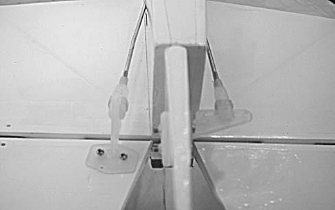
11 2) The control horn of elevator should be mounted on the bottom, right side of the elevator at the leading edge, in line with the elevator pushrod. 2) Using a modeling knife, remove the covering from over the two precut pushrod slots, one on each side of the fuselage, under the rear half of the horizontal stabilizer. Drill two 1,6mm holes through the elevator using the control horn as a guide and screw the control horn in place. 3) Install the elevator pushrod by threading string down through the pushrod exit slot on the right side of the fuselage and into the servo compartment. The control horn of rudder should be mounted on the left side of the rudder at the leading edge, in line with the rudder pushrod. 4) Tie the string onto the threaded end of the elevator pushrod and carefully pull the pushrod through the fuselage and out the exit slot. Drill two 1,6mm holes through the ruuder using the control horn as a guide and screw the control horn in place. 5) Thread one nylon clevis on to the pushrod at least 1/4 ''. Attach the clevis to the elevator control horn. Some bends in the wire will be necessary eliminate any binding. See photo #19 below. See photo # 18a and #18b below. Elevator control horn Elevator pushrod Rudder pushrod 24a Rudder control horn 25 6) Repeat steps 3-5 above for the rudder pushrod. The rudder pushrod. Will exit out the left side of the fuselage. See photo #19 above. 24b 7) Install an adjustable servo connector in the hole closest to the center of the rudder servo arm. You need to use a "dual type" servo arm. Install an adjustable servo connector 3-4 holes out from the center of the servo arm. Install the connector using the same technique as with the ailerons. Do not permanently attach the adjustable servo connector for the throttle as it may need to be moved late. See figure # 6 below. Servo Installation 1) Locate the three servos you will be using for the rudder, elevator and throttle. Use the hardware provided with the servos of your radio system to mount them in the servo tray. Position the servo with the output shafts as shown. See figure #5 below. FIGURE #5 FRONT THROTTLE SERVO CONNECTOR RUDDTOR ELEVATOR FIGURE# 6 RUDDER ARM 10 THROTTLE ARM
12 8) Connect the servo to your radio's receiver and turn on the system. Set the trim tabs on the transmitter to neutral and center the servo arms. The elevator and rudder servo arms should be perpendicular to the servos. For the throttle, we suggest setting the throttle trim tab and the throttle stick to the lowest setting which will be used to shut off the engine. Also mount the servo arm about 450 back from perpendicular. See photo # 7 below. FIGURE # ) Insert the nosegear pushrod wire through the adjustable servo connector on the rudder servo arm. Hold the nose gear assembly in the neutral position and tighten the set screw in the servo connector. Roll the airplane on the ground to ensure it rolls straight. If not, adjust the pushrod wire. When satisfied, cut off the excess wire. FRONT 15) Glue the second of the two 1/2'' *1/2''*1/4'' pieces of wood between the fuselage side and the steering pushrod housing to help hold the housing in place and prevent it from flexing. Use the same technique as with the throttle. See photo # 20 above. 9) One at a time, hold the pushrods in position over the respective servo to check for proper servo direction. If any servo turns in the wrong direction, switch your radio's reversing switches as necessary to achieve the correct direction. 16) With the elevator in neutral, mark where the pushrod wire crosses the servo arm. Place a Z-bend in the wire at the mark made. Attach the servo arm to the wire and cut off the excess wire. 10) Slide the throttle pushrod wire through the adjustable servo connector on the throttle servo arm. Pull the carburator barrel to the fully closed position. Tighten the set screw in the connector. 17) Repeat step # 16 for the rudder pushrod. Notice the position of the servo arm on the servo. See photo # 21 below. 11) Move the throttle stick and trim tab to the full throttle position. The carburetor barrel should be opened fully. If it is not, move the adjustable servo connector on the servo arm out one hole. If the servo moves too far, and the pushrod binds, move the adjustable servo connector in one hole on the servo arm. You should adjust the linkage so full forward stick and trim should be idle. Full back stick and full back trim should close the carburetor barrel, which in use will stop the engine. Rudder pushrod Throttle pushrod Elevator pushrod 27 12) When satisfied with the pushrod assembly cut off the excess wire and permanently attach the adjustable servo connector to the servo arm. 13) Glue one of the 1/2'' *1/2''*1/4'' pieces of wood between the fuselage side and the throttle pushrod housing to help hold the housing in place and prevent it from flexing. See photo # 20 below. Throttle pushrod 11 28
13 Receiver & Battery Installation Control Throws 1) The battery should be wrapped in foam and mounted under the fuel tank to add in balancing. We used a 500mah flat pack. The receiver should be wrapped in foam and mounted just behind the fuel tank. High rate Ailerons: 1/2'' up & down Elevator: 5/8''up & down Rudde: 1'' right & left 2) Uncoil the receiver antenna completely and drill a 1/16'' hole in the side of the fuselage, opposite the muffler, for the antenna to exit. Secure the end of the antenna to the top the vertical fin using a rubber band or similar method. Low rate 3/8'' up & down 3/8'' up & down 1/2''right & left ** Note** Both the center of gravity and the control throws are a good starting place for initial test flying and may be changed to your particular tastes and flying styles once you have become familiar with the. We do recommend initially flying the airplane using the LOW RATE settings. Too much throw can force the plane into a high speed stall, so remember, "More it not better". 3) Install the switch on the side of the fuselage opposite the muffler. Use the faceplate of the switch as a pattern for drilling the holes and the cutout for the switch itself. Flight preparation Balancing 1) Check the operation and direction of the elevator, rudder, ailerons and throttle. 1) It is critical that your airplane be balanced correctly. Improper balance will cause your plane to lose control and crash. The center of gravity is located 2-1/2'' back from the leading edge of the wing at the fuselage sides. This location is recommended for initial test flying and trimming. There is a 3/8'' margin forward and aft, but it is not recommended that the center of gravity be located any further back than 2-7/8''. Balance the with the fuel tank empty. A) Plug in your radio system per the manufacturer's instructions and turn everything on. B) Check the elevator first. Pull back on the elevator stick. The elevator should go up. If it does not, flip the servo revesing switch on your transmitter to change the direction. C) Check the rudder. Looking from behind the airplane, move the rudder stick to the right. The rudder should move to the right. The nose wheel should move t the right as well. If it does not, flip the servo reversing switch on your transmitter to change the direction. 2) Using a couple of pieces of masking tape or a pen, make a mark on each side of the top of the wing 2-1/2'' back from the leading edge. 3) Turn the upside down and place your fingers on the marks on top of the wing and carefully lift the plane. D) Check the throttle. Moving the throttle stick forward should open the carburetor barrel. If it does not, flip the servo reversing switch on your transmitter to change the direction. 4) If the nose of the plane falls, the plane is nose heavy. To correct this, try moving your battery pack back. It that is not enough change, add a little lead weight to the tail. If the tail of the plane falls, double check that you have mounted the battery pack under the fuel tank. If the airplane is still tail heavy add lead weight to the firewall or even better, use a sufficient heavy hub under the spinner. E) From behind the airplane, look at the aileron on the right wing. Move the aileron stick to the right. The aileron should move up and the other aileron should move down. If it does not, flip the servo reversing switch on your transmitter to change the direction. 12
14 Flying the 2) Check Control Surface Throw. A) The rudder should move 1/2'' left and 1/2'' right from center. If you are unfamiliar with flying low wing sport aircraft, please seek out an experienced pilot to help you with the first few flights of the airplane. The design of the allows the airplane to fly smoothly and stable, yet perform good aerobatics as well. Landings are smooth and predictable, but because this is not a primary trainer, its stall speed is higher and power should be used to bring it in for landings and slow speed flight. It does not have the self-recovery characteristics of a primary R/C trainer, so again, if you don't feel comfortable for the first flight have someone with more experience help you get it in the air. B) The elevator should move 3/8'' up and 3/8'' down from center. C) The aileron should move 3/8'' up and 3/8'' down from center. If they move too far, move the adjustable horn away from the aileron a few turns. Do the opposite if there is not enough throw. It is important that both ailerons move the same amount, both up and down. D) Once the control throws and movements are set, tubing must be added to the clevises to ensure they do not release in the air. Cut 1/4'' lengths of fuel tubing and slide one over each clevis prior to attaching it to the control horn. This will ensure the clevis will not release in flight. Although this model has good low speed characteristics with power on, you should always build up as much speed as your runway will permit before lifting off, as this will give you a safety margin in case the engine quits after take off. It is important that the plane rolls out on the ground until sufficient airspeed is achieved. Pulling the off the ground too soon could result in a stall and crash. Allow the airplane to pick up speed and gently lift off and climb out gradually. We recommend that you take it easy with your for the first several flights, gradually getting acquainted with the air plane and allowing your engine to fully break-in. Add and practice one maneuver at a time, learning how the airplane be haves in each. For smooth flying and normal maneuvers, we recommend using the low rate settings described earlier, Hight rate may be required for more crisp aerobatics.before your first landing, practice landing approaches in the air. This will get you familiar with the stall characteristics of the. Pre-Flight Check 1) Completely charge your transmitter and receiver batteries before your first day of flying. 2) Check every bolt and every glue join in your to ensure everything is tight and well bonded. 3) Check that the tubes used for clevis retainers are in place. 4) Double check the balance of the airplane. Do this before filling the tank with fuel. 5) Check the control surfaces. All should move in the correct direction and not bind in any way. When it's time to land, fly a normal landing pattern and approach decreasing power to about one-quarter. It is important that when power is reduced and flying speed has diminished, do not make high angle turns onto the final approach. Too hight an angle of bank with too litter power can cause the airplane to stall. When you turn final, reduce power to just a few clicks over idle. When you are a few feet off the ground, reduce power to idle and let the airplane settle onto the runway. Land slightly faster than the stall speed and on the main wheels, as this is the easiest way to land the and will reduce the risk of stalling the airplane. 6) Check the receiver antenna. It should be fully extended and not still coiled up in the fuselage. 13
15 I/C FLIGHT WARNINGS Always operate in open areas, away from factories, hospitals, schools, buildings and houses etc. NEVER fly your aircraft close to people or built up areas. THE PROPELLER IS DANGEROUS Keep fingers, clothing (ties, shirt sleeves, scarves) or any other loose objects that could be caught or drawn in, away from the propeller. Take care at ALL times. Keep all onlookers (especially small children and animals) well back from the area of operation. This is a flying aircraft, which will cause serious injury in case of impact with a person or animal. NEVER fly near power lines, aerials or other dangerous areas including airports, motorways etc. NEVER use damaged or deformed propellers or spinners. NEVER fly in wet conditions or on windy or stormy days. ALWAYS adjust the engine from behind the propeller, and do not allow any part of your body to be in line with the propeller. 14 DO NOT dispose of empty fuel containers on a fire, this can lead to an explosion.
16 I/C FLIGHT GUIDELINES When ready to fly, first extend the transmitter aerial. Switch on the transmitter. Operate the control sticks on the transmitter and check that the control surfaces move freely and in the CORRECT directions. ALWAYS land the model INTO the wind, this ensures that the model lands at the slowest possible speed. Check that the transmitter batteries have adequate power. Switch off the receiver. Switch on the receiver. Check that the wings are correctly fitted to the fuselage. ALWAYS take off into the wind. Switch off the transmitter. If the model does not respond correctly to the controls, land it as soon as possible and correct the fault. Empty the fuel tank after flying, fuel left in the tank can cause corrosion and lead to engine problems. Made in Vietnam
Instruction Manual. Specification:
 Instruction Manual L O W Specification: Wingspan: 133 cm (52.3 inches) Length : 104 cm (40.9 inches) Weight : 1790gr Engine : 25-32 two stroke Radio : 4 channel - 4 servo W I N G KIT CONTENTS: We have
Instruction Manual. Wingspan : 1694mm (66.69 in) : 1470mm (57.87 in) : 3200gr gr. : 61 two stroke/ 71 four stroke. : 6 channel / 7 servo
 : 1470mm (57.87 in) : 3200gr gr. : 61 two stroke/ 71 four stroke. : 6 channel / 7 servo") Wingspan : 1694mm (66.69 in) g Length : 1470mm (57.87 in) Weight : 3200gr - 3800gr Engine : 61 two stroke/ 71 four stroke Radio : 6 channel / 7 servo KIT CONTENTS: We have organized the parts as they
Wingspan : 1694mm (66.69 in) g Length : 1470mm (57.87 in) Weight : 3200gr - 3800gr Engine : 61 two stroke/ 71 four stroke Radio : 6 channel / 7 servo KIT CONTENTS: We have organized the parts as they
Instruction Manual. Wingspan : 1884 mm (74.17 in) Length. Weight. Engine. : 4 channels / 5 servo standard. : 1450 mm (57.
 Length. Weight. Engine. : 4 channels / 5 servo standard. : 1450 mm (57.") Wingspan : 1884 mm (74.17 in) Length : 1450 mm (57.09 in) Weight : 4000 gr Engine : 60 two strokes Radio : 4 channels / 5 servo standard KIT CONTENTS: We have organized the parts as they come out of the
Wingspan : 1884 mm (74.17 in) Length : 1450 mm (57.09 in) Weight : 4000 gr Engine : 60 two strokes Radio : 4 channels / 5 servo standard KIT CONTENTS: We have organized the parts as they come out of the
I/C FLIGHT GUIDELINES
 SPECIFICATION - Wingspan: 3500mm (137.8 in) - Length: 1650mm (64.96 in) - Flying weight: 3700-4000 gr - Wing area: 75 dm2 - Wing loading: 49g/dm2 - Wing type: HQ profile - Covering type: Genuine ORACOVER
Instruction Manual. Wingspan : 2270mm (89.37 inches) : 1870mm (73.62 inches) : 7400gr gr. : 4 channel - 6 standard servo.
 : 1870mm (73.62 inches) : 7400gr gr. : 4 channel - 6 standard servo.") Wingspan : 2270mm (89.37 inches) g Length : 1870mm (73.62 inches) Weight : 7400gr - 7600gr Radio : 4 channel - 6 standard servo Engine : 25cc-35cc KIT CONTENTS: We have organized the parts as they come
Wingspan : 2270mm (89.37 inches) g Length : 1870mm (73.62 inches) Weight : 7400gr - 7600gr Radio : 4 channel - 6 standard servo Engine : 25cc-35cc KIT CONTENTS: We have organized the parts as they come
HIGH WING MK2 GP/EP ARF SCALE
 SONIC HIGH WING MK2 GP/EP.25-.32 ARF SCALE 1:10 SPECIFICATION - Wingspan: 1340mm (52.7in) - Length: 1040mm (40.9 in) - Flying weight: 1800-2000 gr - Wing area: 27 dm2 - Wing loading: 79g/dm2 - Wing type:
: 6 channel - 9 servo
 g Wingspan : 2005mm (78.94 inches) Length : 1640mm (64.57 inches) Weight : 6400g - 6600g Engine : 25cc - 35cc Radio : 6 channel - 9 servo KIT CONTENTS: We have organized the parts as they come out of
Instruction Manual. Wingspan : 1400mm (55.12 in) : 1370mm (53.94 in) : 2600gr gr. : 4 channel / 5 servo. : / 2 stroke_52-71 / 4 stroke
 : 1370mm (53.94 in) : 2600gr gr. : 4 channel / 5 servo. : / 2 stroke_52-71 / 4 stroke") Instruction Manual 540 Wingspan : 1400mm (55.12 in) g Length : 1370mm (53.94 in) Weight : 2600gr - 2800gr Radio : 4 channel / 5 servo Engine : 46-52 / 2 stroke_52-71 / 4 stroke KIT CONTENTS: We have organized
Instruction Manual 540 Wingspan : 1400mm (55.12 in) g Length : 1370mm (53.94 in) Weight : 2600gr - 2800gr Radio : 4 channel / 5 servo Engine : 46-52 / 2 stroke_52-71 / 4 stroke KIT CONTENTS: We have organized
1660mm (65.4 in) 1200mm (47.2 in) 2700gr gr 6 channel - 7 servo standard 46/ 2 stroke or 52/ 4 stroke
 1200mm (47.2 in) 2700gr gr 6 channel - 7 servo standard 46/ 2 stroke or 52/ 4 stroke") Instruction Manual CESSNA-46 1660mm (65.4 in) 1200mm (47.2 in) 2700gr - 3000gr 6 channel - 7 servo standard 46/ 2 stroke or 52/ 4 stroke KIT CONTENTS: We have organized the parts as they come out of the
Instruction Manual CESSNA-46 1660mm (65.4 in) 1200mm (47.2 in) 2700gr - 3000gr 6 channel - 7 servo standard 46/ 2 stroke or 52/ 4 stroke KIT CONTENTS: We have organized the parts as they come out of the
RECOMMENDED MOTOR AND BATTERY SET UP
 SPECIFICATION - Wingspan: 1600mm (63 in) - Length: 1285mm (50.5 in) - Flying weight: 2800-3200 gr - Wing area: 40.1 dm2 - Wing loading: 78g/dm2 - Wing type: Naca airfoils - Covering type: Genuine ORACOVER
I n s t r u c t i o n M a n u a l. Instruction Manual SPECIFICATION
 I n s t r u c t i o n M a n u a l Instruction Manual SPECIFICATION - Wingspan: 3200mm (125,9 in) - Length: 1650mm (64,9 in) - Flying weight: 3000gr 3200gr - Wing area: 64.5 dm2 - Wing loading: 46g/dm2
: 7 channel - 9 servo, Hi-Torque ( Minimum 6 kg ).
.") g Wingspan : 1820mm (71.65 inches) Length : 1625mm (63.98 inches) Weight : 6900gr Engine : 25cc - 35cc Radio : 7 channel - 9 servo, Hi-Torque ( Minimum 6 kg ). KIT CONTENTS: We have organized the parts
g Wingspan : 1820mm (71.65 inches) Length : 1625mm (63.98 inches) Weight : 6900gr Engine : 25cc - 35cc Radio : 7 channel - 9 servo, Hi-Torque ( Minimum 6 kg ). KIT CONTENTS: We have organized the parts
RECOMMENDED MOTOR AND BATTERY SET UP
 SPECIFICATION - Wingspan: 1404mm (55.3in) - Length: 1134mm (44. 6 in) - Flying weight: 3.2-3.4 kg - Covering type: Genuine ORACOVER - Spinner size: scale type (not included) - Radio: 4 channel minimum
SBD DAUNTLESS GP/EP SIZE ARF SCALE 1:8. Instruction Manual
 GP/EP SIZE.46-.55 ARF SCALE 1:8 SPECIFICATION - Wingspan: 1440mm (56.7in) - Length: 1140mm (44.9 in) - Flying weight: 3000-3300 g - Wing area: 42 dm2 - Wing loading: 78g/dm2 - Wing type: Naca airfoils
Instruction Manual. Wingspan : 1400 mm (55.12 inch) : 1480 mm (58.27 inch) : 5500gr gr. : 6-9 channel/ 8 servo high torque,1 standard
 : 1480 mm (58.27 inch) : 5500gr gr. : 6-9 channel/ 8 servo high torque,1 standard") Wingspan : 1400 mm (55.12 inch) g Length : 1480 mm (58.27 inch) Weight : 5500gr - 6000gr Radio : 6-9 channel/ 8 servo high torque,1 standard Engine : GT 22 OS KIT CONTENTS: We have organized the parts
Wingspan : 1400 mm (55.12 inch) g Length : 1480 mm (58.27 inch) Weight : 5500gr - 6000gr Radio : 6-9 channel/ 8 servo high torque,1 standard Engine : GT 22 OS KIT CONTENTS: We have organized the parts
RECOMMENDED MOTOR AND BATTERY SET UP
 SPECIFICATION - Wingspan: 1420mm (55.91 in) - Length: 1370mm (53.94 in) - Flying weight: 2600-2800 gr - Wing area: 41.6 dm2 - Wing loading: 65g/dm2 - Wing type: Naca airfoils - Covering type: Genuine ORACOVER
Instruction Manual book
 book SPECIFICATION Wingspan : 1,450 mm 57.09 in. Length : 1,200mm 47.24in. Weight : 3.1 kg 6.82 Lbs. Radio : 05 channels. Servo : 07 servos. Engine : 61-75 2 stroke. 91 4 stroke. Made in Vietnam. This
RECOMMENDED EDF AND BATTERY SET UP
 SPECIFICATION - Wingspan: 1150mm (45.3 in) - Length: 1587mm (62.5 in) - Flying weight: 5.0-5.3 kg - Wing area: 40dm2 - Wing loading: 125g/dm2 - Wing type: Naca airfoils - Covering type: Genuine ORACOVER
the leading edge of the wing, at the fuselage - Length: 1540mm (60.6 in) 10% expo; High: 15mm up/down, 10% expo - Wing area: 40dm2
 10% expo; High: 15mm up/down, 10% expo - Wing area: 40dm2") SPECIFICATION - Gravity CG: 165-170 mm (6.5-6.7 in) Back from - Wingspan: 1400mm (55.1 in) the leading edge of the wing, at the fuselage - Length: 1540mm (60.6 in) - Control throw Ailerons: Low: 12mm up/down,
SPECIFICATION - Gravity CG: 165-170 mm (6.5-6.7 in) Back from - Wingspan: 1400mm (55.1 in) the leading edge of the wing, at the fuselage - Length: 1540mm (60.6 in) - Control throw Ailerons: Low: 12mm up/down,
HERO 3D SCALE 1:6 ARF
 Instruction Manual SPECIFICATION - Wingspan: 1500mm(59 in) - Length: 1410mm (55.5 in) - Flying weight: 2100-2300 gr - Wing area: 58 dm2 - Wing loading: 39g/dm2 - Covering type: Genuine ORACOVER - Gear
RECOMMENDED MOTOR AND BATTERY SET UP
 SPECIFICATION - Wingspan: 6000mm (236.2 in) - Length: 2873mm (113.1 in) - Flying weight: 14-18 kg - Wing area: 219.4 dm2 - Wing loading: 64g/dm2 - Wing type: HQ airfoils - Covering type: Genuine ORACOVER
Instruction Manual. Wingspan : 1670mm. : 3400gr gr. : 61/75 two stroke. : 5 servo + 1 servo retract / 6 channel
 Wingspan : 1670mm g Length Weight Engine Radio : 1350mm : 3400gr - 4000gr : 61/75 two stroke : 5 servo + 1 servo retract / 6 channel KIT CONTENTS: We have organized the parts as they come out of the box
to fly. Most hardware included and all replacement parts are available.
 Instruction Manual The Thunderbolt P47 was perhaps the greatest of world war II in terms of all round performance and capability Phoenix Model has recreated a 2C - 60 class engine (or 4c 91 class) It was
RECOMMENDED MOTOR AND BATTERY SET UP
 Instruction Manual SPECIFICATION - Wingspan: 1418mm (55.8 in) - Length: 1314mm (51.7 in) - Flying weight: 2700-3200 gr - Wing area: 36.8 dm2 - Wing loading: 76g/dm2 - Wing type: Naca airfoils - Covering
Instruction Manual book
 Instruction Manual book SPECIFICATION Wingspan : 1,800mm. 70.87 in. Length : 1,350 mm. 53.15in. Weight : 3.6kg. 7.92lbs. Parts Listing required (not included). Glow Engine : 55-61 2 stroke. 91 4 stroke.
INSTRUCTION MANUAL BOOK
 INSTRUCTION MANUAL BOOK ITEM CODE BH57. SPECIFICATION Wingspan: 1,470 mm. 57.87 in. Length : 1,180 mm. 46.46 in. Weight : 2.7 Kg. 5.94 Lbs. Engine : 46 cu.in 2 stroke. 52 cu.in 4 stroke. Radio : 4 channels.
RECOMMENDED MOTOR AND BATTERY SET UP
 SPECIFICATION - Wingspan: 2567mm (101in) - Length: 2190mm (86.2 in) - Flying weight: 11-13 kg - Wing area: 101 dm2 - Wing loading: 99g/dm2 - Wing type: Naca airfoils - Covering type: Genuine ORACOVER -
RECOMMENDED MOTOR AND BATTERY SET UP
 SPECIFICATION - Wingspan: 1669mm (65.7in) - Length: 1229mm (48.43 in) - Flying weight: 3300-3400 gr - Wing area: 44.2 dm2 - Wing loading: 67g/dm2 - Wing type: Naca airfoils - Covering type: Genuine ORACOVER
SIZE.120 OR 30CC SCALE 1:5 ARF
 PC21 PILATUS MK2 SIZE.120 OR 30CC SCALE 1:5 ARF SPECIFICATION - Wingspan: 1772mm (69.72in) - Length: 2019mm (79.5 in) - Flying weight: 6.4-7.2 kg - Wing area: 57.6 dm2 - Wing loading: 113g/dm2 - Wing type:
RECOMMENDED MOTOR AND BATTERY SET UP
 SPECIFICATION - Wingspan: 2000mm (78.7in) - Length: 1544mm (60.7 in) - Flying weight: 3600-3800 gr - Wing area: 66 dm2 - Wing loading: 55g/dm2 - Wing type: Naca airfoils - Covering type: Genuine ORACOVER
RECOMMENDED MOTOR AND BATTERY SET UP
 SPECIFICATION - Wingspan: 1410mm (55.5 in) - Length: 1278mm (50.3 in) - Flying weight: 3.2-3.4 kg - Wing area: 41.3 dm2 - Wing loading: 75g/dm2 - Wing type: Naca airfoils - Covering type: Genuine ORACOVER
Instruction Manual book
 book SPECIFICATION Wingspan : 1,920 mm 75.59 in. Length : 1,560 mm 61.42 in. Weight : 5 kg 11.00Lbs. Radio : 06 channels. Servo : 09 servos. Engine : 120 4 stroke. Made in Vietnam. This instruction manual
RECOMMENDED MOTOR AND BATTERY SET UP
 SPECIFICATION - Wingspan: 2190mm (86.2 in) - Length: 1907mm (75 in) - Flying weight: 9000-12000 gr - Wing area: 92 dm2 - Wing loading: 98g/dm2 - Wing type: Naca airfoils - Retract gear type: Air-retract
RECOMMENDED MOTOR AND BATTERY SET UP
 SPECIFICATION - Wingspan: 1800mm (70.8 in) - Length: 1355mm (53.3 in) - Flying weight: 4100-4300 g - Wing area: 51 dm2 - Wing loading: 80g/dm2 - Wing type: Naca airfoils - Covering type: Genuine ORACOVER
Instruction Manual book
 book ITEM CODE:BH 115. SPECIFICATION Wingspan : 6,000 mm 236,22 in. Length : 2,740 mm 107,87 in. Weight : 17.5kg 38.5Lbs. Radio : 08 channels. Servo : 07-08 HS-5685MH(HITEC) Battery : 2 Cells-Li-Po 7.4V
Instruction Manual book
 Instruction Manual book SPECIFICATION Wingspan : 1,920 mm 75.59 in. Length : 1,560 mm 61.42 in. Weight : 5 kg 11.00Lbs. Radio : 06 channels. Servo : 09 servos. Engine : 120 4 stroke. Made in Vietnam. JU87-STUKA
Instruction Manual book
 Instruction Manual book SPECIFICATION Wingspan : 1,920 mm 75.59 in. Length : 1,560 mm 61.42 in. Weight : 5 kg 11.00Lbs. Radio : 06 channels. Servo : 09 servos. Engine : 120 4 stroke. Made in Vietnam. JU87-STUKA
ALMOST READY TO FLY. Wing Span in cm. 2
 ASSEMBLY MANUAL ALMOST READY TO FLY MS:X9 Specifications Wing Span --------------------------61.4 in ---------------------------156cm. 2 Wing Area --------------------------606.1 sq.in ------------------
Instruction Manual book
 book SPECIFICATION Wingspan : 2,080 mm 81.89 in. Length : 1,680 mm 66.14 in. Weight : 6.2 kg 13.64 Lbs. Radio : 06 channels. Servo : 06 servos. Engine : 30-35 CC Gas(FUJI IMVAC). Made in Vietnam. This
Instruction Manual MUSTANG P51 - EP. Wingspan : 1377mm (54.21in) : 1180mm (46.46 in) : 2200gr gr. : AXI motor 2826 or 4120
 : 1180mm (46.46 in) : 2200gr gr. : AXI motor 2826 or 4120") Instruction Manual MUSTANG P51 - EP Wingspan : 1377mm (54.21in) g Length : 1180mm (46.46 in) Weight : 2200gr - 2600gr Engine : AXI motor 2826 or 4120 Radio : 4 channel / 4 servos standard KIT CONTENTS:
Instruction Manual MUSTANG P51 - EP Wingspan : 1377mm (54.21in) g Length : 1180mm (46.46 in) Weight : 2200gr - 2600gr Engine : AXI motor 2826 or 4120 Radio : 4 channel / 4 servos standard KIT CONTENTS:
Instruction Manual book
 Instruction Manual book ITEM CODE:BH118. SPECIFICATION Wingspan : 1,050 mm 41.34 inches. Length : 950mm 37.4 inches. Weight : 1 kg 2.2 lbs. Radio : 04 channels. Servo : 4 mini servos. Motor : KMS 2814/05
SBACH SCALE 1:4 ½ ARF
 SPECIFICATION - Wingspan: 1663mm (65.5 in) - Length: 1638mm (64.5 in) - Flying weight: 4700-5200 gr - Wing area: 56 dm2 - Wing loading: 85g/dm2 - Wing type: Naca airfoils - Covering type: Genuine ORACOVER
ASSEMBLY MANUAL. Graphics and specifications may change without notice.
 NEMESISMS: SEA 111 ASSEMBLY MANUAL Graphics and specifications may change without notice. Specifications Wing span------------------------------------- 55.9in ------------------------------- 142cm. Wing
Instruction Manual book
 Instruction Manual book ITEM CODE: BH56. SPECIFICATION Wingspan : 1,660 mm 65.35 in. Length : 1,420 mm 55.91 in. Weight : 3.8 kg 8.36 Lbs. Radio : 06 channels. Servo : 08 servos. Engine : 75 Cu.in 2 Stroke.
Instruction Manual book
 Instruction Manual book SPECIFICATION Wingspan : 2,170 mm 85.43 in. Length : 1,760 mm 69.29 in. Weight : 6.3 kg 13.86 Lbs. Radio : 06 channels. Servo : 08 servos. Engine : 45-50CC Gas. Made in Vietnam.
ALMOST READY TO FLY. Wing Span in cm. 2
 ASSEMBLY MANUAL ALMOST READY TO FLY MS: X12 A - B Graphics and specfications may change without notice. Kit features. Specifications Wing Span ------------------------------- 42.7 in ---------------------
Instruction Manual book
 Instruction Manual book SPECIFICATION Wingspan : 1,780 mm 70.08 in. Length : 1,520 mm 59.84 in. Weight : 4.8 kg 10.56 Lbs. Radio : 06 channels. Servo : 09 servos. Engine : 120 4stroke Made in Vietnam.
Instruction Manual book
 book SPECIFICATION Wingspan : 2,310 mm 90.94 in. Length : 1,750 mm 68.90 in. Weight : 8.4 kg 18.48 Lbs. Radio : 06 channels. Servo : 09 servos + 2 mini servos (elevator). Engine : 45-55CC gas. Made in
MS:159 ASSEMBLY MANUAL. Graphics and specifications may change without notice.
 ASSEMBLY MANUAL MS:159 Graphics and specifications may change without notice. Specifications: Wing span ----------------------------61.8in (157cm). Wing area -----------------1100.5sq.in (71.0sq dm). Weight
Instruction Manual book
 book Item code:bh131 SPECIFICATION Wingspan : 3,000 mm 118.1 in. Length : 1,600 mm 62.99 in. Weight : 2.2 kg 4.84 Lbs. Radio : 05 channels. Servo : 06 mini servos. Electric Motor: BOOST 40 Battery : 3celIs
TUCANO 60CC SCALE 1:4 ¼ ARF. Instruction Manual. version. version
 Instruction Manual GP EP version version SCALE 1: ¼ ARF SPECIFICATION - Wingspan: 567mm (101in) - Length: 190mm (86. in) - Flying weight: 11-13 kg - Wing area: 101 dm - Wing loading: 99g/dm - Wing type:
MS:176 ASSEMBLY MANUAL. Graphics and specifications may change without notice.
 ASSEMBLY MANUAL MS:176 Graphics and specifications may change without notice. Specifications: Wing span ------------------------------98.4in (250cm). Wing area ----------------1576.4sq.in (101.7sq dm).
Instruction Manual book
 book ITEM CODE: BH99. SPECIFICATION Wingspan : 2,850 mm 112.20 in. Length : 1,910 mm 75.20 in. Weight : 8.1 kg 17.82 Lbs. Radio : 06 channels. Servo : 08 servos. Engine : 35 CC gas. Made in Vietnam. This
Instruction Manual book
 Instruction Manual book ITEM CODE: BH39. SPECIFICATION Wingspan : 181 cm 71.26 inches. Length : 155 cm 61.024 inches. Weight : 04 kg 8.8 lbs. Servo : 9 servos. Radio : 6 channels. Engine : 91 cu.in - 2
ASSEMBLY MANUAL. Kit features. MS:76
 ASSEMBLY MANUAL MS:76 Graphics and specfications may change without notice. Specifications: Wingspan---------------------------------------------------- 82.8 in------------------------------------- 210.3cm.
Instruction Manual book
 Instruction Manual book ITEM CODE: BH122. SPECIFICATION Wingspan : 2,200 mm 86.61 in. Length : 1,640 mm 64.57 in. Weight : 6.5 kg 14.3Lbs. Parts listing required (not included). Radio : 8 channels. Servo
(Glider) ASSEMBLY MANUAL
 ASSEMBLY MANUAL") (Glider) MS:132 ASSEMBLY MANUAL Graphics and specifications may change without notice. Specifications: Wing span ------------------------------118.1in (300cm). Wing area ---------------------902.1sq.in
(Glider) MS:132 ASSEMBLY MANUAL Graphics and specifications may change without notice. Specifications: Wing span ------------------------------118.1in (300cm). Wing area ---------------------902.1sq.in
ASSEMBLY MANUAL. Kit features. MS:110
 MS:110 ASSEMBLY MANUAL Graphics and specifications may change without notice. Specifications: Wing span-------------------------------------------------- 62.9 in---------------------------------------
Instruction Manual book
 Instruction Manual book Item code:bh117 SPECIFICATION Wingspan : 2,100 mm 82.68 in. Length : 1,875 mm 73.82 in. Weight : 7.5 kg 16.5 Lbs. Parts listing required (not included) Radio : 08 channels. Servo
Instruction Manual book
 Instruction Manual book ITEM CODE:BH118. SPECIFICATION Wingspan : 1,050 mm 41.34 inches. Length : 950mm 37.4 inches. Weight : 1 kg 2.2 lbs. Radio : 04 channels. Servo : 4 mini servos. Motor : BL2215/20
ARF TRAINER KIT ASSEMBLY MANUAL BOOMERANG EP. ALMOST READY TO FLY
 WWW.SEAGULLMODELS.COM ASSEMBLY MANUAL BOOMERANG EP ARF TRAINER KIT Graphics and specifications may change without notice. MS: 211 ALMOST READY TO FLY Specifications: Wingspan---------------56.0 in (142.2
YAK54 MK2. GP/EP size.120/20cc SCALE 1:4 ¾ ARF. Instruction Manual. version. version
 Instruction Manual GP EP version version GP/EP size.10/0cc SCALE 1:4 ¾ ARF SPECIFICATION - Wingspan: 168 (66.3 in) - Length: 1605mm (63.1 in) - Flying weight: 4700-500 gr - Wing area: 54.7 dm - Wing loading:
CAP 232 ASSEMBLY MANUAL
 CAP 232 MS: ASSEMBLY MANUAL SEA 91 Graphics and specfications may change without notice. Specifications Wingspan------------------------------------ 65 in --------------------------------- 165cm. Wing
Instruction Manual. We wish you many enjoyable flights with your plane and once again thank you for your choosing a Phoenix Model product
 Instruction Manual Wing span: 1590mm (626 in) Length: 1100mm (433 in) Weight: 1500gr - 1700gr Motor: AXI 2814/10 or Motor: 500-600 w/ gear box Radio: 4 Channel / 4 servos standar Propeller: 12 x 47 We
ASSEMBLY MANUAL. Kit features. MS:88
 MS:88 ASSEMBLY MANUAL Graphics and specfications may change without notice. Specifications: Wingspan-------------------------------------------------- 70.9 in--------------------------------------- 180cm.
MS:183 ASSEMBLY MANUAL. Graphics and specifications may change without notice.
 MS:183 ASSEMBLY MANUAL Graphics and specifications may change without notice. Specifications: Wing span ------------------------------79.9in (203cm). Wing area -----------------1165.6sq.in (75.2sq dm).
Instruction Manual book
 book ITEM CODE:BH 72 SPECIFICATION Wingspan : 2,350 mm 92.52 in. Length : 1,730 mm 68.11 in. Weight : 6.4 kg 14.08 Lbs. Radio : 06 channels. Servo : 08 servos. Engine : OS. GT22-26cc gas. Made in Vietnam.
LASER 200. Hand-made Almost Ready to Fly R/C Model Aircraft ASSEMBLY MANUAL
 LASER 200 Hand-made Almost Ready to Fly R/C Model Aircraft ASSEMBLY MANUAL SPECIFICATIONS: WING SPAN ----------------------------------------175CM -------------------------------- 68.75 in. WING AREA ------------------------------------------4746CM2
Instruction Manual book
 Instruction Manual book SPECIFICATION Wingspan : 2,060 mm 81.10 in. Length : 1,460 mm 57.48 in. Weight : 4.8 kg 10.56 Lbs. Radio : 06 channels. Servo : 07 servos. Engine : 46 2 stroke (2pcs). Made in Vietnam.
Instruction Manual book
 book ITEM CODE:BH 145 SPECIFICATION Wingspan: 6,000mm 236.22 in. Length : 2,800 mm 110.24 in. Weight : 18.5 kg 40.7 Lbs. Parts listing required (not included). Radio : 07-08 channels. Servo : 09-10 standard
Instruction Manual book
 Instruction Manual book Item code:bh117 SPECIFICATION Wingspan : 2,100 mm 82.68 in. Length : 1,875 mm 73.82 in. Weight : 7.5 kg 16.5 Lbs. Radio : 08 channels. Servo : 09 servos. Engine : 33-45cc gas. Made
Instruction Manual Book
 Book ITEM CODE: BH99. SPECIFICATION Wingspan : 2,850 mm 112.20 in. Length : 1,910 mm 75.20 in. Weight : 8.1 kg 17.82 lbs. Parts listing required (not included): Radio : 06 channels. Servo : 08 standard
Instruction Manual book
 book ITEM CODE:BH 124 SPECIFICATION Wingspan : 2,240 mm 88.19 in. Length : 1,625 mm 63.98 in. Weight : 6,4 kg 14.08Lbs. Radio : 08 channels. Servo : 09 servos. Engine : 26-35cc Gas. Made in Vietnam. This
ASSEMBLY MANUAL. Specifications
 ASSEMBLY MANUAL MS: SEA 82 Graphics and specfications may change without notice. Specifications Wingspan-------------------------------------- 70.9 in------------------------------ 180cm. Wing area-------------------------------------
Instruction Manual book
 Instruction Manual book ITEM CODE:BH 140 SPECIFICATION Wingspan : 2,050mm 80.71 in. Length : 1,840 mm 72.41 in. Weight : 6.8kg 14.96 Lbs. Radio : 07 channels. Servo : 09 servos. Engine: O.S GT 33 CC gas.
Instruction Manual book
 book ITEM CODE: BH109 SPECIFICATION Wingspan : 2,200mm. 86.61 in. Length : 1,976 mm. 77.80in. Weight : 8.3 kg. 18.26 lbs. Part listing required (not included) Glow Engine : 55 CC Gas Servo : 9 servos.
Instruction Manual book
 book SPECIFICATION Wingspan : 1.750mm 68.90 in. Length : 1.280 mm 50.39 in. Weight : 3.2-3.5 kg 7.04-7.7 Lbs. Radio : 06 channels. Servo : 07-09 mini servos +3 servos retracts (FUTABA,S3170G) Parts listing
EXTRA 330LX. Specifications: Code: SEA274. Graphics and specifications may change without notice. ASSEMBLY MANUAL
 ASSEMBLY MANUAL EXTRA 330LX Code: SEA274 Graphics and specifications may change without notice. Specifications: Wingspan---------------82.0 in (208.2 cm). Wing area---------------1349.4 sq.in ( 87.1 sq.dm).
Instruction Manual book
 book ITEM CODE:BH101. SPECIFICATION Wingspan : 1,940 mm 76.38 inches. Length : 1,700 mm 66.93 inches. Weight : 5.8 kg 12.76 lbs. Radio : 6 channels. Servo : 8 servos. Glow Engine : 26-30cc gas. Made in
Instruction Manual book
 Instruction Manual book Item code:bh133 SPECIFICATION Wingspan : 1,400 mm 55.12 in. Length : 1,350 mm 53.15 in. Weight : 3.7 kg 8.14 Lbs. Radio : 08-09 channels. Servo : 08-09 servos. EDF : Turingy SK3
Instruction Manual book
 Instruction Manual book ITEM CODE: BH120. SPECIFICATION Wingspan : 1,600 mm 62.99 in. Length : 1,184 mm 46.61 in. Weight : 3.1 kg 6.82Lbs. Radio : 5 channels. Servo : 04-05 servos Engine : 46-2 stroke
Instruction Manual BULLDOG. Wingspan : 1410 mm (55.5in) : 1450 mm (57.1in) : 4900gr gr. Weight. : 6-9 Channel/ 7 servo high torque, 1standard
 : 1450 mm (57.1in) : 4900gr gr. Weight. : 6-9 Channel/ 7 servo high torque, 1standard") Wingspan : 1410 mm (55.5in) Length Weight Radio Engine : 1450 mm (57.1in) : 4900gr - 5600gr : 6-9 Channel/ 7 servo high torque, 1standard : 1.20/ 2 stroke 1.80/ 4 stroke KIT CONTENTS: We have organized
Wingspan : 1410 mm (55.5in) Length Weight Radio Engine : 1450 mm (57.1in) : 4900gr - 5600gr : 6-9 Channel/ 7 servo high torque, 1standard : 1.20/ 2 stroke 1.80/ 4 stroke KIT CONTENTS: We have organized
INSTRUCTION MANUAL BOOK
 INSTRUCTION MANUAL BOOK ITEM CODE: BH 36. SPECIFICATION Wingspan : 1,620 mm 64 in. Length : 1,340 mm 53 in. Weight : 3.8 Kg 8.36 Lbs. Engine : 15 CC Gas Radio : 8 Channels Servo : 8Servos + 2 servos Retract
P-40C TOMAHAWK. Instruction Manual Book. Item code: BH % ALMOST READY TO FLY SPECIFICATION
 Instruction Manual Book. P-40C TOMAHAWK INCLUDING AIR RETRACT. AIR UP, AIR DOWN, TURN AND TWIST OLEO STRUTS LANDING GEAR. ALL BALSA - PLY WOOD CONSTRUCTION. COVERED IN A HEAT-SHRINK FILM WITH PRINTED.
Instruction Manual book
 book ITEM CODE:BH 136 SPECIFICATION Wingspan : 2,000mm 78.74 in. Length : 1,760 mm 69.29 in. Weight : 6.8kg 14.96 Lbs. Parts listing required (not included). Engine : 0.S GT 33cc gas Radio : 07 channels.
DECATHLON. Hand-made Almost Ready to Fly R/C Model Aircraft ASSEMBLY MANUAL
 Hand-made Almost Ready to Fly R/C Model Aircraft ASSEMBLY MANUAL SPECIFICATIONS: WING SPAN ----------------------------------------172CM -------------------------------- 67.75 in. WING AREA --------------------------------------49.17Sq.dm
ASSEMBLY MANUAL. Specifications
 Kit features. Ready-made minimal assembly & finishing required. Ready-covered covering. Photo-illustrated step-by-step Assembly Manual. ASSEMBLY MANUAL Specifications Wingspan--------------------------------
SUPER DECATHLON. Instruction Manual Book 95% ALMOST READY TO FLY. Item code: BH150. SPECIFICATION
 Instruction Manual Book Item code: BH150. SUPER DECATHLON ALL BALSA - PLY WOOD CONSTRUCTION. COVERED WITH ORACOVER. 95% ALMOST READY TO FLY SPECIFICATION Wingspan: 2,450mm (96.46in). Length: 1,750mm (68.90in).
TURBO BEAVER. Instruction Manual Book. Item code: BH % ALMOST READY TO FLY ALL BALSA - PLY WOOD CONSTRUCTION. COVERED WITH ORACOVER
 Instruction Manual Book. TURBO BEAVER ALL BALSA - PLY WOOD CONSTRUCTION. COVERED WITH ORACOVER 95% ALMOST READY TO FLY SPECIFICATION: - Wingspan: 2,250 mm (88.58 in). Length: 1,675 mm ( 65.94 in). Weight:
Instruction Manual book
 Instruction Manual book ITEM CODE:BH135 SPECIFICATION Wingspan : 4,200mm. 163.35 in. Length : 2,100 mm. 82.68 in. Weight : 7,6 kg. 16.72lbs Radio : 07 channels. Servo : 05 06 standard high torque servos,
HARMON ROCKET III. Hand-made Almost Ready to Fly R/C Model Aircraft ASSEMBLY MANUAL
 HARMON ROCKET III Hand-made Almost Ready to Fly R/C Model Aircraft ASSEMBLY MANUAL Specifications Wingspan---------------------------------------- 50.4 in---------------------------- 128cm. Wing area---------------------------------------
Instruction Manual book
 book Item code:bh77 SPECIFICATION Wingspan : 1,740 mm 68.50 in. Length : 1,440 mm 56.69 in. Weight : 4.4 kg 9.68 Lbs. Radio : 06 channels. Servo : 09 servos + 2 mini servos(wheel door). Engine : 120-4
Instruction Manual EXTRA 260-EP. 1075mm (42.32 in) 1000mm (39.37 in) 1100gr gr. 4 channel - 4 mini servo. Axi motor 2820
 1000mm (39.37 in) 1100gr gr. 4 channel - 4 mini servo. Axi motor 2820") 1075mm (42.32 in) 1000mm (39.37 in) 1100gr - 1400gr 4 channel - 4 mini servo Axi motor 2820 KIT CONTENTS: We have organized the parts as they come out of the box for better identification during assembly.
1075mm (42.32 in) 1000mm (39.37 in) 1100gr - 1400gr 4 channel - 4 mini servo Axi motor 2820 KIT CONTENTS: We have organized the parts as they come out of the box for better identification during assembly.
Specifications. Kit features.
 A S S E M B L Y M A N U A L MS:58 Graphics and Specfications may change without notice. Specifications Wingspan---------------------------------------- 70.9 in---------------------------- 182cm. Wing area----------------------------------------
Instruction Manual book
 book (pusher propeller) ITEM CODE:BH 142 SPECIFICATION Wingspan : 1,450mm 57.09 in. Length : 1,165 mm 45.87 in. Weight : 3.3kg 7.26 Lbs. Radio : 05 channels. Servo : 07 size (29 x 13 x 30) mm. Electric
Instruction Manual book
 book ITEM CODE:BH 139 SPECIFICATION Wingspan : 1,450mm 57.09 in. Length : 1,140 mm 44.88 in. Weight : 3.3kg 7.26 Lbs. Radio : 05 channels. Servo : 07 mini servos+ 3servos Retracts (FUTABA S3170G) EDF:
ASSEMBLY MANUAL. Specifications
 ASSEMBLY MANUAL MS: SEA 82 Graphics and specfications may change without notice. Specifications Wingspan-------------------------------------- 70.9 in------------------------------ 180cm. Wing area-------------------------------------
RADIO CONTROL MODEL ASSEMBLY INSTRUCTIONS. Wasp
 RADIO CONTROL MODEL ASSEMBLY INSTRUCTIONS Wasp TRAINER Almost ready-to-fly Wingspan 1520mm Fuselage length 1105mm Engine: 40-46 2T / 52-60 4T Electric Motor: 600-700W Radio: 5 channel / 4-5 servo RC Functions:
Instruction Manual book
 Instruction Manual book Item code:bh144 SPECIFICATION Wingspan : 1,400 mm 55.12 in. Length : 1,350 mm 53.15 in. Weight : 4 kg 8.8 Lbs. Empty Weight: 1.9 kg 4.18 lbs Radio : 08 channels. Servo : 08 size
ASSEMBLY MANUAL. Specifications
 MS:56H Kit features. Specifications Wingspan ------------------------------ 63 in -------------------------- 160cm. Wing area ----------------------------- 728 sq.in ------------------ 47 sq.dm. Weight