NOVALYNX CORPORATION MODEL ANALOG OUTPUT EVAPORATION GAUGE INSTRUCTION MANUAL
|
|
|
- Lester Mathews
- 6 years ago
- Views:
Transcription
1 NOVALYNX CORPORATION MODEL ANALOG OUTPUT EVAPORATION GAUGE INSTRUCTION MANUAL REVISION DATE: AUGUST 2015
2 Receiving and Unpacking Carefully unpack all components and compare to the packing list. Notify NovaLynx Corporation immediately concerning any discrepancy. Inspect equipment to detect any damage that may have occurred during shipment. In the event of damage, any claim for loss must be filed immediately with the carrier by the consignee. Damages to equipment sent via Parcel Post or UPS require the consignee to contact NovaLynx Corporation for instructions. Returns If equipment is to be returned to the factory for any reason, call NovaLynx between 8:00 a.m. and 4:00 p.m. Pacific Time to request a Return Authorization Number (RA#). Include with the returned equipment a description of the problem and the name, address, and daytime phone number of the sender. Carefully pack the equipment to prevent damage or additional damage during the return shipment. Call NovaLynx for packing instructions in the case of delicate or sensitive items. If packing facilities are not available take the equipment to the nearest Post Office, UPS, or other freight service and obtain assistance with the packaging. Please write the RA# on the outside of the box. Warranty NovaLynx Corporation warrants that its products are free from defects in material and workmanship under normal use and service for a period of one year from the date of shipment from the factory. NovaLynx Corporation's obligations under this warranty are limited to, at NovaLynx's option: (i) replacing; or (ii) repairing; any product determined to be defective. In no case shall NovaLynx Corporation's liability exceed product's original purchase price. This warranty does not apply to any equipment that has been repaired or altered, except by NovaLynx Corporation, or that has been subjected to misuse, negligence, or accident. It is expressly agreed that this warranty will be in lieu of all warranties of fitness and in lieu of the warranty of merchantability. Address NovaLynx Corporation 431 Crown Point Cir Ste 120 Grass Valley, CA USA Phone: (530) Fax: (530) nova@novalynx.com Website: Copyright by NovaLynx Corporation i
3 TABLE OF CONTENTS Section No. Page No. 1.0 INTRODUCTION General Description Gauge Design Use of Gauge with Evaporation Pan Evaporation Gauge Tester (Optional) Automatic Evaporation Pan Refill System (Optional) Evaporation Logger (Optional) SPECIFICATIONS INSTALLATION Unpacking Site Selection Leveling the Gauge Testing for Leaks Wiring OPERATION CALIBRATION TROUBLESHOOTING General Inspection Power Cables Float Natural Influences Evaporation Pan Maintenance DRAWINGS AND DATA LOGGER PROGRAMMING ii
4 MODEL EQUIPMENT CONFIGURATION AND IDENTIFICATION iii
5 1.0 INTRODUCTION 1.1 General Description NovaLynx Corporation Model Analog Output Evaporation Gauge Instruction Manual The Analog Output Evaporation Gauge has been designed to accurately measure the changing water level in an evaporation pan. The evaporation gauge provides an electrical signal proportional to the water level. The data provided can be used to determine the evaporation rate of the water. Although it may be used with a variety of evaporation measuring equipment, the evaporation gauge is normally used with a standard Class A National Weather Service Evaporation Pan (NovaLynx Model ). 1.2 Gauge Design The evaporation gauge design includes a float, a counter-weight, a chain attached to both the float and counter-weight, and a sprocket attached to a precision 1000 ohm potentiometer. The gauge components are all mounted inside a protective enclosure. The housing of the evaporation gauge has been designed to act as a stilling well for the float to help eliminate rapid fluctuations in the measurements. The housing is constructed to hold the water inside it without any leakage to the outside. By using the built-in water pipe coupler, the gauge can be attached to the NovaLynx Evaporation Pan to remotely sense the water level. NovaLynx provides a six-foot interconnecting pipe assembly under model number P/F and a six inch long pipe assembly model number P/FS. The NovaLynx pipe and fittings are stainless steel and the fittings include a stainless steel union to join the two pieces of pipe. This design helps eliminate any influences the gauge may introduce into the evaporation pan measurements which can occur when the gauge is installed inside the evaporation pan. 1.3 Use of Gauge with Evaporation Pan As the level of the water inside the evaporation pan changes, the water inside the evaporation gauge will change to the same level. The float moves on top of the water surface. The float transfers its motion through the chain to the sprocket. The sprocket, in turn, causes the shaft of the potentiometer to rotate, changing the resistance of the potentiometer. Using a regulated dc power source, typically +5 Vdc, to excite the potentiometer, a voltage that varies from zero to Vdc can be measured at the wiper of the potentiometer. The voltage from the potentiometer can be then be translated into inches of evaporated water. The output of the potentiometer is normally wired to give a decreasing voltage as the water level decreases (increasing amount of evaporated water but decreasing water height). In some situations the gauge may be 1
6 employed as a water level sensor measuring both increasing as well as decreasing levels of water. The maximum amount of water level that can be measured by the gauge is 10 inches. 1.4 Evaporation Gauge Tester (Optional) To aid the user in the setup, testing, and reading measurements of the evaporation gauge, NovaLynx has developed a handheld tester, Model B. The tester connects to the evaporation gauge output signal terminal block and converts the sensor's resistance into a direct reading of the evaporation pan water level in inches or in millimeters. The tester features an easy-to-read LCD. The tester is self-contained and battery-powered, offering plug and play operation. 1.5 Automatic Evaporation Pan Refill System (Optional) Evaporation gauges are often used with data loggers to collect and store the data at the gauge location until it is transmitted or downloaded to the operator's computer. NovaLynx has created an automatic evaporation pan refill device, Model A. If a water supply line or water tank is available at the site, the A will turn on the water until the pan is refilled to a level of about 8.5 inches. This can be set to occur daily, weekly, or every few days. The refill time is set by the user. NovaLynx recommends using a refill time such as midnight when evaporation is least likely to occur. 1.6 Evaporation Logger (Optional) The B is a voltage data logger that can be connected to the Evaporation Gauge to provide a direct display readout and data logging record of the evaporation pan water level. 2.0 SPECIFICATIONS GENERAL Height: 27-1/2" (700 mm) Diameter: 8" (203 mm) Weight: 7-1/2 lbs (3.4 kg) Shipping weight: 15 lbs (6.8 kg) Cable: 50' of 3-conductor, 24 AWG, shielded Signal connector: 3-pin terminal block, standard (opposite end of cable terminated to meet monitoring equipment interface requirements) Float: 4" diameter, plastic Counterweight: 4 oz (114 g), stainless steel Water input port: 1/2" NPT coupling, female Base dimensions: 16" triangle with leveling screws Total resolution: 0.03" (0.76 mm) 2
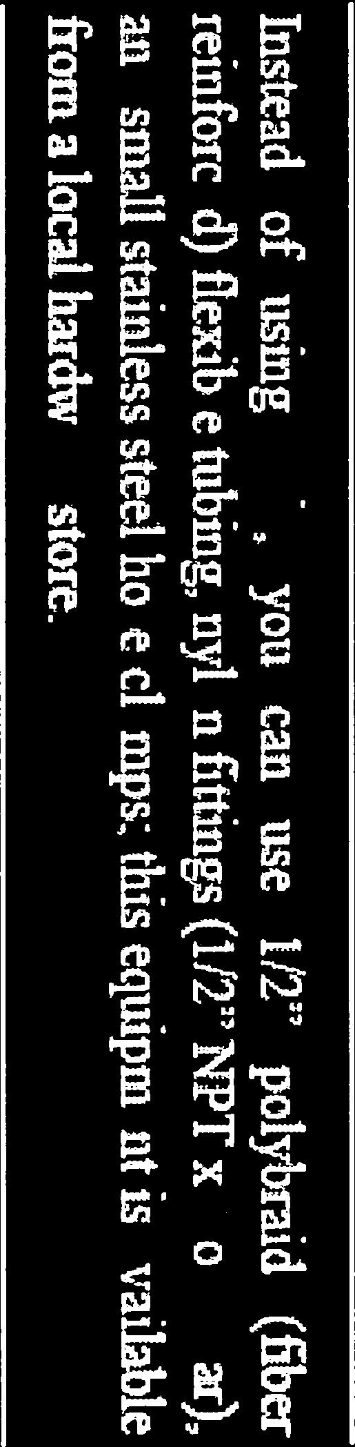
7 POTENTIOMETER Accuracy: 0.25% Rotation: 360 continuous Electrical angle: 340, ± 1 (20 gap) Resistance: 1,000 ohms, ± 10% Operating temperature:* -40 to +140 F (-40 to +60 C) *Evaporation is normally not measured at temperatures below freezing Linearity: 0.25% Mechanical range: 0 to 10" (0 to 254 mm) Electrical range: 0 to inches (0 to mm) 3.0 INSTALLATION 3.1 Unpacking Carefully unpack all of the evaporation gauge. Remove the top cover. The float with chain and counter-weight are shipped inside the bottom of the gauge housing. Remove packing material from inside the housing. The float cannot be removed without removing the pot/gear assembly housing. Use caution when removing packing materials and parts from inside the gauge. Take care to avoid hitting the potentiometer sprocket wheel. 3.2 Site Selection The evaporation gauge water reservoir is physically connected to the pan by using a 1/2" diameter pipe. Threaded couplings are provided on both the pan and the gauge. Typically, 1/2" rigid water pipe is used to connect the gauge to the pan. A flexible hose tubing may be used, provided it does not deteriorate in outdoor weather conditions. The gauge should be placed far enough away from the pan and on the North side to avoid casting any shadows or reflections inside or onto the sides of the pan. Shadows will affect the evaporation process. Both the evaporation pan and the gauge need to be as level as possible in order to maximize the amount of water that can be poured into and measured in the pan. A level pan will provide uniform exposure of the water to the atmosphere, eliminating uneven depths of water. The site should be level and free of nearby obstructions that can cast shadows or reflect sunlight onto the evaporation pan. The pan should be placed upon a wooden platform over soil typical of the area. Level the platform before installing the pan. Place the pan so that the water pipe fitting faces the evaporation gauge. A second platform for mounting the gauge may be needed in order to place the bottom of the gauge at the same elevation as the pan. 3
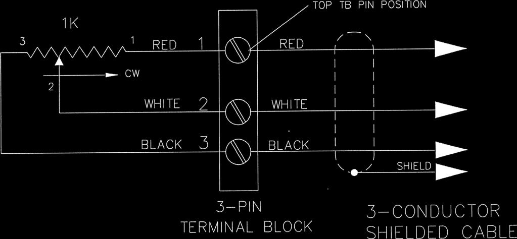
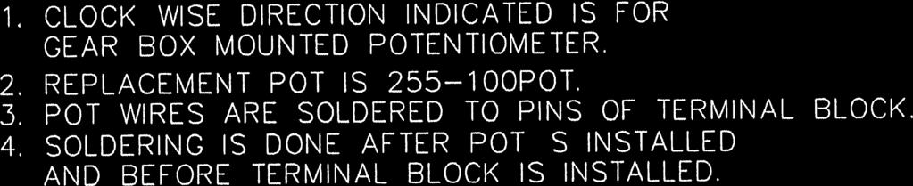
8 3.3 Leveling the Gauge Level the gauge by adjusting the three leveling screws located on the triangular base. With the top cover removed, place a carpenters level across the opening and check the level. Adjust the screws until the air bubble in the level is centered. After leveling the gauge look down inside the stillwell to make certain that the float and chain hang down straight and are centered in the gauge. The float must be free to move up and down without making contact with the sides of the gauge. 3.4 Testing for Leaks After connecting the gauge to the pan and all electrical connections are in place, fill the evaporation pan with the desired amount of water and carefully check all of the joints for leaks. Using Teflon tape or plumbers pipe joint compound at each threaded coupling will help prevent leaks. 3.5 Wiring Whenever the gauge is to be used with other equipment, the output signal wiring may vary depending upon the way that the gauge is to be used. The signal and power wires are connected into the gauge through a three-pin terminal block. The terminal block is mounted onto the side of the potentiometer housing. To access the terminal block, the cover must be removed from the gauge. Four screws hold the cover in place. The signal cable is terminated with three spade lugs. The spade lugs are attached to the screws of the terminal block. Refer to the gauge schematic to obtain wiring details. The opposite end of the cable will generally be stripped and tinned. Refer to the table presented below for wiring details Output Signal Connections Power Input 5 Vdc (typical) RED TB PIN 1 ~ TOP Evap Signal 0-5 Vdc (wiper) WHITE TB PIN 2 ~ MIDDLE Power Ground GND BLACK TB PIN 3 ~ BOTTOM 4.0 OPERATION The evaporation gauge potentiometer exhibits a varying resistance in response to the motion of the float. Applying a voltage across the potentiometer allows monitoring of the gauge by a data logger or any other electronic voltage sensing instrument. The output signal of the potentiometer can be configured to give an increasing or a decreasing voltage with regards to the changing level of the water. For most systems provided by NovaLynx, the signal is configured so that a decrease in the water level is represented by a decrease in the gauge voltage. 4
9 The actual starting water level measurement is not critical, 8.5" or 9". The reading that is critical is the change or evaporation measured from the starting reference level. The gauge will never read below about 2.5 inches. This is when the float physically hits the bottom of the gauge and there is still 2.5 inches of water present. A typical range is 4 inches to 9 inches. Above 9.5 inches wind could blow water over the edges. Below 4 inches the low level of water absorbs more heat from the sun and pan bottom reflections, causing increased evaporation. Note: During winter months when the water may freeze, NovaLynx recommends draining the pan and storing the pan and the evaporation gauge indoors. 5.0 CALIBRATION The actual calibration is normally done within the measuring device, converting the output voltage change into change in inches or millimeters. Proper calibration of the evaporation gauge is critical to the accuracy of the data as well as to the correct operation of the gauge. Calibration of the gauge should be performed upon initial installation of the gauge and whenever the gauge is removed from its platform or from inside the evaporation pan. The evaporation gauge must be calibrated in order to set the operating range of the potentiometer and to determine the zero point of the float motion. For data logging systems, the slope and intercept data will be measured or calculated from the calibration of the gauge. After the gauge has been calibrated, the operator needs only to keep track of the amount of water added back into the evaporation pan. With the gauge calibrated, the gauge may be used to measure the amount of water added into the pan each week. The following procedure is used to properly calibrate the evaporation gauge. Record the calibration values whenever possible in order to check the gauge calibration during the year. Note: The actual measuring device or data logger, when properly set up, can be used as the indicating device. This will eliminate the resistance measurements and mathematical calculations described below. 5.1 Upon completion of the gauge and pan installation, fill the evaporation pan with approximately eight inches of water. The water height can be checked by using a ruler or a tape measure. Check the evaporation gauge to ensure that the water has filled the stillwell to the correct height inside the gauge. 5.2 Disconnect the signal cable from the evaporation gauge. Use a digital ohmmeter to measure the resistance of the pot across terminal block pins (2) middle (+) and (3) bottom (-). Rotate the sprocket and you will notice the resistance value 5
10 changes from 0 to 1000 ohms. Rotate the sprocket slowly until the reading jumps to a floating condition or reads 0. This is the dead band. It has a mechanical range of about 20. Some pots may be exactly 1K ohm, but most will vary by ± 15 ohms. There is a white line marked on the front side of the sprocket. When this line is vertical, the pot should be in the 20 gap area. 5.3 Check to make certain that the float is hanging down near the center of the evaporation gauge. As viewed from the front of the gauge, looking toward the face of the sprocket wheel, the float should hang from the right side of the sprocket wheel with the counter-weight to the left side of the wheel. A white line is painted on the front of the sprocket. When viewed from the front, the line should be at the 11 o clock or 30 position when the float is resting on the bottom of the gauge. 5.4 Move the float by hand down toward the bottom of the gauge. As soon as the float contacts the bottom surface of the gauge, hold the float in position and check to see that the chain is straight and tight. The chain must not be moving nor pulled downward other than by the tension exerted by the float. Measure the resistance of the potentiometer. 5.5 The potentiometer should be at its point of low resistance for the range of motion of the pot. The resistance should be above zero ohms but may be as large as 150 ohms. If the value appears to be floating or within the deadband of the potentiometer, the sprocket wheel must be adjusted with relation to the chain. The potentiometer must not cross into or go beyond the deadband as the float approaches and touches the bottom of the gauge. To adjust the sprocket, allow the float to return to the top of the water. Lift the chain off the sprocket and rotate the sprocket counter-clockwise one or two gear tooth positions. Replace the chain and repeat step 5.4. Repeat step 5.5 until the chain is properly positioned on the sprocket. Be sure to observe the ohmmeter to detect any crossover of the deadband as the float is moved downward. 5.6 Record the resistance of this Bottom or Zero position of the float. If the gauge is connected into the monitoring equipment and power has been applied, measure the voltage at this position as well as the resistance. Measure the position of the center of the float with respect to the bottom of the evaporation pan for pan mounted gauges. For gauges mounted outside the pan, measure the water level inside the gauge to the center of the float. Usually, the center of the float is aligned with the center of the threaded pipe fitting on the housing when the float touches the bottom of the gauge. 5.7 Move the float back to the top of the water and let go of the float. The center of the float should now be even with the surface of the water. Measure the resistance and voltage of the potentiometer at this position. Also measure the water level at this point with respect to the bottom of the pan. The resistance of the potentiometer should be high at this point and approaching the 1000 ohm end of the pot. If the chain and sprocket have been properly set, the 6
11 potentiometer should not move past the 1000 ohm end of the element and stop in the deadband. If it appears that the pot is in its deadband at the top of the water level, then either the sprocket and chain must be adjusted further or there is too much water in the pan and some water must be drained. Typically this setting should be offset slightly to avoid going into the gap area. When the pan is full to the brim, the resistance should be between 950 and 995 ohms. When the pan is empty or less than 2-1/4" deep, the resistance should be between 20 and 90 ohms. 5.8 At this point the slope and intercept information can be generated and the operating curve of the instrument can be calculated. The operating curve can then be verified by setting the float to several points of water level and by comparing the actual output voltage to the calculated voltage. Remember the gap is 20 therefore 340 /360 = With a 5.00 volt excitation applied, a 5 volt reading on the wiper means 9.44" not 10.0". The formulas are: Y = m*x + b m = (Y 2 - Y 1) (X 2 - X 1) b = Y 1 - mx1 where Y is inches of water, X is ohms or volts, m is the slope of the line and b is the zero offset. For a range of 10 inches and a potentiometer resistance of 1000 ohms the calculation reveals that b = 0, and m = For a range of 10 inches and a voltage range of 5 Vdc, b = 0 and m = If the float range of motion happens to be 1.5 to 8.0 inches, then the output voltage can be calculated as 0.75 and volts, respectively. Use the actual values measured in the preceding steps (4.2, 4.4, 4.6, and 4.7) with the above formulas to determine the operating line of the gauge. The line should be linear allowing calculation of intermediate outputs for known positions of the float. 6.0 TROUBLESHOOTING 6.1 General Inspection Always disconnect the reporting/recording device from its power source before making any changes to the wiring connections. If possible, troubleshoot the gauge immediately whenever any of the following conditions are observed: severe weather has recently occurred, the gauge does not appear to operate normally or exhibits a marked change in performance, data is missing or appears to be incorrect, the gauge has been dropped or damaged, water has damaged the wiring or electronic components, water has been allowed to dry out totally in the evaporation pan. 7
12 Remember a 90 rotation on the sprocket should indicate a change of 2.50 inches on your reporting/recording device, 180 would be a 5.00 inch change. A 1 inch change is equal to approximately 7.6 gallons of water decrease inside the evaporation pan. 6.2 Power If the gauge does not register correctly, first check the power connections. Check the voltage with a voltmeter. Be sure the reporting/recording device has been powered up correctly. If the reporting/recording device uses batteries for its primary source of power, check the batteries to be sure they have sufficient voltage and that they are securely in place. Check the battery terminals to ensure that they are clean and provide solid contact. 6.3 Cables Check the sensor cable connections both at the gauge and at the control unit. Cable shorts or opens can cause loss of data. If a connection is found to be loose, reattach the wire and check to see if the problem has been corrected. Check for damage to the cable insulation. Replace the cable if it appears that the jacket has been worn or cut. 6.4 Float Inspect the float and chain to make certain that they have not become entangled. Whenever the evaporation pan has been allowed to empty or dry out completely, the float may tip sideways at the bottom of the gauge and the chain may become kinked at the mechanical connector. Test the motion of the float to ensure that it moves smoothly and freely. 6.5 Natural Influences A number of naturally occurring events can influence the evaporation gauge reading and may appear as errors or as a gauge malfunction. These natural events include animals drinking the water, birds bathing in the water, leaves and debris falling into the pan, high level winds, unreported rainfall or snow during the night, and thermal expansion of the water and metal parts. 6.6 Evaporation Pan Maintenance Additional errors in the evaporation gauge measurement may be related to maintenance of the evaporation pan. The pan must be kept free of algae. Plants must not be allowed to grow up and over the edges of the pan. Dirt and dust must not be allowed to accumulate inside the pan. Most of these problems are alleviated by regular rinsing of the pan. 8
13 The growth of algae in the evaporation pan can be discouraged by the addition of small amounts (5 to 10 mg/liter) of copper sulphate (available at farm and garden supply stores) to the water, however, algae already present must be removed by a thorough cleaning of the pan. In severe cases, spa chemicals may be used to combat algae, however, the addition of chemicals to the water will slightly influence the evaporation process. During months when freezing conditions are likely, empty, clean, and store the pan. The pan should be stored indoors. If it must be left in the fenced enclosure, it should be turned bottom side up and secured to the platform with stout rope. 7.0 DRAWINGS AND DATA LOGGER PROGRAMMING 9
14 SIMPLIFIED - QUICK START - SET -UP Information for Setting up The Evaporation Gauge The Evaporation Gauge should be and unpacked, leveled and connected to the Evaporation Pan. A Digital Volt/Ohm Meter D.V.M. should be Used, but is Not mandatory. l 1. Measure the Resastance Between The White & Black Wires If You Do Not Have a D.V.M. See Step 6 2. Rotate the Sprocket to Read between 40 to 80 ohms. ( white line should be poibted around 11 oclock ) 3. Attach the Float I Chain Assembly onto the Sprocket See Dwg. (Float hanging on Right Side as viewed from the Front) 4. With the Float Resting on the Bottom on the Gauge the Resistance should read between 40 to 80 ohms 5. If the reading Not between 40 to 80 ohms Then, Lift the chain off the sprocket & rotate it as needed one or two gear tooth positions. Replace the chain and repeat step 3 & 4 Sprocket Chain The White Line is pointing at 11 O'clock when viewed from Front Float float Resting on the Bottom 6. SET- UP - If You DO NOT Have a D.V.M A White Line is painted on the Front Side of the Sprocket, When Viewed from the Front Side, Rotate the chain sprocket, so that the White Line is pointing at 11 O'clock or 30 left on Vertical 7. Attach the Float I Chain Assembly onto the Sprocket as Shown. With the Float hanging on Right Side as viewed from the front The float should be Resting on the Bottom. When Water enters into the Evaporation Gauge the Chain Sprocket will rotate Counter Clock-wise Approximate Readings shown with respect to the Position on the white Line>>> 1 o'clock- 9.0 inches 3 o'clock- 7.2 inches 6 o'clock- 4.7 inches Attach the 3 conductor cable to your Data Logger or measuring Device. 9 o'clock inches Refer to the Manual for a more detailed Set-Up Procedure.
15
16
17


18


19


20
21 SAMPLE SENSOR SET- UP for the WS-16 Modular Weather Station (c) Novalynx Corporation Inc. Sensor Types 1. Generic 2. Wind Speed 3. Wind Direction 4. Temperature 5. Humidity 6. Pressure 7. Precipitation 8. Solar Radiation 9. Evaporation 10. Soil Moisture 11. Water Level Select type [1-11] or quit [Q]: 9 Evaporation Sensors Select model [1-1] or quit [Q]: 1 Sensor Input Channel 1. Pulse Counter P1 2. Pulse Counter P2 3. Pulse Counter P3 4. Analog Input AO (typical input channel) 5. Analog Input A 1 6. Analog Input A2 7. Analog Input A3 8. Analog Input A4 9. Analog Input AS 10. Analog Input A6 11. Analog Input A? 12. Analog Input A8 13. Analog Input A9 Select channel [1-13] or quit [Q]: 4 ************************************************************************************************************************* GENERIC Data Logger I RTU I PLC I Signal Conditioner (Assuming 5.00 Vdc Excitation Voltage) The Evaporation Gauge can be set up One of 2 ways 1. Direct Reading of Water level in Pan... Example : 1.44" to 9.44" = 2. Direct Reading, with a positive Offset of Water level in Pan Example : 2.50' to " No 2 is the preferred Method, Because the Gauge will not go into the Gap Area Evap. Measurements are Measured as a Change over time Example : inches per Day The Exact Water Level in the Pan is Not Important, Only the difference in Change Vw =Wiper Voltage V+ =Excitation Voltage L = level of water inches L= Vw x V+
22 ** SAMPLE INPUT INSTRUCTIONS ** (For Campbell Scientific Data Loggers CRSOO & CR1000) For Evaporation Gauge (scaled in inches. Range 0.00 to 9.44') With 2500 mv Excitation NOTE: When the Float is touching the bottom of the Evap. Gauge, the chain linkage should be set for a output signal that is slightly positive. ie. 50 to 250 mv. The Evaporation is Normally Calculated as Daily Totals. Example: Start 7.65" after 24 hrs. 6.87" Daily Evaporation= = 0.78 inches per day The Exact physical Level in the Pan Is Not Needed for Evaporation Measurements. The Difference or Change from one time to another is all that is Necessary. '\\\\\\\\\\\\\\\\\\\\\\\\\ DECLARATIONS Public Evap_inch 'Measurement instruction. Sensor using excitation channel 1 and single ended 'ended channel 1. BrHalf(Evap_inch, 1, mv2500, 1, VX1, 1, 2500, False, 20000,250, 9.425, 0) WIRING CONNECTIONS Red: Connect to EX1, EX2, or EX3 (the one that is programmed.) Black: Connect to any ground symbol (Analog ground) White: Connect to SE Channel (the one that is programmed.) Shield (Bare Wire):Connect to any G (if necessary. Not required for general operation.)

23 EVAPORATION GAUGE ACCESSORIES Novalynx Corporation- Phone A Automatic Refill System The automatic refill system provides a simple method to automatically refill an evaporation pan at specified times. It consists of an electronic water timer and an automatic float valve. The water timer switches on at a user-specified time, allowing water from an external water source to flow into the pan. The float valve will stop the water flow at approximately 8-1/2" to 9-1/2" depending upon the water pressure. The timer then shuts off until the next programmed time. Specifications Power: one 9 volt battery Operating temperature: 0-50 C Operating humidity: 0-100% Water connection: Std garden hose fitting Housing: Aluminum and plastic, waterproof Size: 8" x 6" x 4" approx B Evaporation Gauge Tester The evaporation gauge tester is used to provide a direct reading in inches on millimeters, of the pan level when connected to the evaporation gauge. The tester is used to set-up the evaporation gauge during initial installation and can also be used to provide a direct reading of evaporation loss. Specifications Range: 0 to inches or 255 millimeters Temp range: oo to 50 C Resolution: inches I 0.01 mm Accuracy: ± 0.1 % of reading Display: 5 digit digit, LCD Batteries: two AAA batteries Size: 3" H x 4.5" W x 1.2" D B Evaporation Logger The Modei B Evaporation Logger is a data logger with LCD Display that can be connected to the Analog Output Evaporation Gauge. The logger is mounted inside a waterproof enclosure and attached externally to the Evaporation Gauge it has clear cover to allow viewing the current Pan Level. The logger is set up to record the evaporation pan level in inches or millimeters. ( please specify when ordering ) The logger is an 16 bit device and can provide a 0.002" resolution. The Software provides, Easy Logger Setup Direct Connect USB, Stored Data is collected by Direct USB cable to a Laptop or PC. Graphing: View multiple parameters on one graph, Zoom and axis-control tools, Logger Status: Verify logger operation and current readings. Export Data to Other Programs: Microsoft Excel or other ASCII-compatible programs Requires two AAA 1.5V alkaline batteries w I 1year Battery life. Stored Data is collected by a Direct USB 2.0 Interface Cable connected to a Laptop or PC. Specifications Inputs: 4 channel logging Vdc inputs (16 bit) Channel 1 is setup for the Evaporation Pan Level Channels 2, 3, and 4 can be used as temperature inputs Measurement capacity: 1.9 million measurements Download in 90 sec. for full memory via Direct USB Interface Programmable Sample rate 1 sec to 18 hours Programmable Start Time I or push-button start Operating temperature: -20 to +7o c (-4 to +158.F) Timekeeping accuracy: ± 1 minute per week at 2o c Battery: two AAA 1-year battery life Outer enclosure size: 5" x 5" x 3 - weight 1.2 lbs Mounting : 8 inch diameter hose clamp attached to Evaporation Gauge
NOVALYNX CORPORATION MODEL 200-WS-02F WIND SPEED & DIRECTION SENSOR INSTRUCTION MANUAL
 NOVALYNX CORPORATION MODEL 200-WS-02F WIND SPEED & DIRECTION SENSOR INSTRUCTION MANUAL REVISION DATE: MAY 2005 Receiving and Unpacking Carefully unpack all components and compare to the packing list. Notify
RS-110 Rainfall Sensor Installation Guide
 RS-110 Rainfall Sensor Installation Guide for XR440 and XR5 Data Loggers September 2015 Revision 1.1 1 Disclaimer The following warranty and liability disclaimer apply to this product. PACE SCIENTIFIC
HydroLynx Systems, Inc. Model 5033-XX Solar Panel. Instruction Manual
 HydroLynx Systems, Inc. Model 5033-XX Solar Panel Instruction Manual Document No: A102759 Document Revision Date: December, 2004 HydroLynx Systems, Inc. Model 5033-XX Solar Panel Receiving and Unpacking
MODEL SIT -6E PAVEMENT-MOUNTED SNOW AND ICE SENSOR
 MODEL SIT -6E PAVEMENT-MOUNTED SNOW AND ICE SENSOR DESCRIPTION The Snow Switch Model SIT 6E Pavement-Mounted Snow and Ice Sensor reliably detects snow and ice conditions on pavement surfaces when used
LTX RF LEVEL SENSOR. Instruction Manual
 LTX RF LEVEL SENSOR Instruction Manual FOR MODELS LTX01, LTX02, LTX05 Intempco Document No: LTX - M01 Rev. 1 Issue Date: April 2005 LTX01 RF LEVEL SENSOR USER MANUAL Software Rev : Rev. Date : June 2004
HDI inch Choke Position Indicator User s Manual Rev Indicator Gauge Linear Potentiometer
 HDI 2522 4-inch Choke Position Indicator User s Manual Rev 2 New 2522 Indicator Gauge Linear Potentiometer w/open Housing 2200 Indicator Gauge Linear Potentiometer TABLE OF CONTENTS HDI 2522 4-inch Indicator
1' to 10' deep and 1' to 25' deep
 ULTRASONIC ECHO-SCALE TM SCALE: INDICATOR: ECHO-SCALE TM NONE PROVIDED electronic sensors for vessels 1' to 10' deep and 1' to 25' deep INSTALLATION & OPERATION s/n 1-800-893-6723 Fax: 925-686-6713 www.forceflow.com
ETgage Model E Instructions
 EXTERNAL WIRING Unclip and drop down the bottom compartment of the instrument to expose the circuit board. Insert lead-in wires through the 3/16-inch diameter hole in the side of the instrument, and through
METEOROLOGICAL INSTRUMENTS
 METEOROLOGICAL INSTRUMENTS INSTRUCTIONS PRECIPITATION GAUGE MODEL 50202 / 50203 R.M. YOUNG COMPANY 2801 AERO PARK DRIVE, TRAVERSE CITY, MICHIGAN 49686, USA TEL: (231) 946-3980 FAX: (231) 946-4772 WEB:
BAK1500 INSTALLATION/OWNER'S MANUAL Compact Amplified Subwoofer
 BAK1500 INSTALLATION/OWNER'S MANUAL Compact Amplified Subwoofer PREPARATION Getting Started Thank you for purchasing the Dual BAK1500 compact amplified subwoofer. Although Dual has attempted to ensure
EL Beam Sensors Standard & SC Versions
 EL Beam Sensors Standard & SC Versions 56801399 Copyright 2008 Slope Indicator Company. All Rights Reserved. This equipment should be installed, maintained, and operated by technically qualified personnel.
Installation Manual Model 3800/3810
 Installation Manual Model 3800/3810 Thermistors & Thermistor Strings No part of this instruction manual may be reproduced, by any means, without the written consent of Geokon, Inc. The information contained
MODEL HSC-24 AUTOMATIC SNOW/ICE MELTING SYSTEM CONTROL PANEL
 MODEL HSC-24 AUTOMATIC SNOW/ICE MELTING SYSTEM CONTROL PANEL DESCRIPTION The Snow Switch Model HSC-24, 24-volt Pavement-Mounted Snow and Ice Sensor reliably detects snow and ice conditions on pavement
Refinery Supply Company, Inc.
 Refinery Supply Company, Inc. OPERATING INSTRUCTIONS Super Pressure Dead Weight Tester Catalog No. 35260 Serving the Oil & Gas Industry since 1923 9133-A East 46th Street Tulsa, Oklahoma 74145-4823 Voice
BEAMER Tilt Beam Sensor
 User s Manual BEAMER Tilt Beam Sensor Serial No. 140 Chestnut Street San Francisco, CA 94111 Phone: 415 364 3200 Fax: 415 861 1448 www.geomechanics.com CAUTION: Never measure the sensor inside your Beamer
The Traveler Series: Adventurer
 The Traveler Series: Adventurer RENOGY 30A Flush Mount Charge Controller Manual 2775 E. Philadelphia St., Ontario, CA 91761 1-800-330-8678 Version: 2.2 Important Safety Instructions Please save these instructions.
The Traveler Series TM : Adventurer
 The Traveler Series TM : Adventurer 30A PWM Flush Mount Charge Controller w/ LCD Display 2775 E. Philadelphia St., Ontario, CA 91761 1-800-330-8678 Version: 3.4 Important Safety Instructions Please save
Model 2008 I Battery Operated Irrigation Timer with 3/4 in. Anti-Siphon Valve
 i n s t r u c t i o n m a n u a l Model 2008 I Battery Operated Irrigation Timer with 3/4 in. Anti-Siphon Valve Features Weekly or cyclical programming 4 start times per day in weekly program Irrigation
6 Gauge Box Set with Programmable Speedometer. Made in the USA. Caution. Speedometer Parts. Tachometer Parts. Fuel Level Gauge Parts.
 6 Gauge Box Set with Programmable Speedometer Caution Disconnect the battery during installation. Tighten nuts on the backclamp only slightly more than you can tighten with your fingers. Six inch-pounds
Manual Installation & Operation
 Manual Installation & Operation Model: NCxxLxx 12A or 30A Solid State Solar Charging Regulator and 12A Load Controller. 231 Patent #: 5,642,030 Applies Page 1 Warnings When Installing, connect grounds,
OWNER S MANUAL EVOLUTION 3500, 4500, 5500, & 8500 SERIES PUMPS
 OWNER S MANUAL EVOLUTION 3500, 4500, 5500, & 8500 SERIES PUMPS IMPORTANT SAFETY INSTRUCTIONS When installing and using this electrical equipment, basic safety precautions should always be followed, including
Global Water Instrumentation, Inc.
 Global Water Instrumentation, Inc. 11390 Amalgam Way Gold River, CA 95670 T: 800-876-1172 Int l: (916) 638-3429, F: (916) 638-3270 Temperature Sensor: WQ101 ph Sensor: WQ201 Conductivity Sensor: WQ301
OPERATING INSTRUCTIONS
 OPERATING INSTRUCTIONS Current Transducer January 2012 Case Backup Washer Connection Stem O Ring Stem Seal Fig. 1 - Current Tranducer UNPACKING Page 2 SPECIFICATIONS Page 2 ACQUAINT YOURSELF WITH THE PARTS
High Frequency SineWave Guardian TM
 High Frequency SineWave Guardian TM 380V 480V INSTALLATION GUIDE FORM: SHF-IG-E REL. January 2018 REV. 002 2018 MTE Corporation High Voltage! Only a qualified electrician can carry out the electrical installation
SSI Technologies - Application Note AT-AN2 Acu-Trac NEMA 4 Liquid Level Sensor Product Overview
 Product Description The Acu-Trac NEMA4 liquid level sensor is a noncontact sensor that is a direct replacement for level senders on tanks with depths up to 1.5 meters (59 inches). The NEMA4 liquid level
LEVEL AND FLOW MEASUREMENT WS131 FLOW METER USER MANUAL.
 LEVEL AND FLOW MEASUREMENT WS131 FLOW METER USER MANUAL www.enoscientific.com Eno Scientific PO Box 1586 Hillsborough, NC 27278 USA www.enoscientific.com 910-778-2660 Copyright Notice Copyright 2015 Eno
Deep-Water EL Tiltmeter
 Deep-Water EL Tiltmeter 56802099 Copyright 2005 Slope Indicator Company. All Rights Reserved. This equipment should be installed, maintained, and operated by technically qualified personnel. Any errors
Data-Logging Rain Gauge PRODUCT MANUAL
 Data-Logging Rain Gauge PRODUCT MANUAL Item # 3554WD1 Thank you for purchasing a Spectrum Datalogging Rain Gauge. With proper installation and care, it will give you years of accurate and reliable measurements.
Installation and Operation Manual
 1645 Lemonwood Dr. Santa Paula, CA 93060 USA Toll Free: 1 (800) 253-2363 Tel: 1 (805) 933-9970 rangerproducts.com Ranger Floor Jack Installation and Operation Manual Manual Revision B July 2017 Manual
F-4600 INLINE ULTRASONIC FLOW METER Installation and Operation Guide
 F-4600 INLINE ULTRASONIC FLOW METER Installation and Operation Guide 11451 Belcher Road South, Largo, FL 33773 USA Tel +1 (727) 447-6140 Fax +1 (727) 442-5699 1054-7 / 34405 www.onicon.com sales@onicon.com
The Traveler Series: Wanderer
 The Traveler Series: Wanderer RENOGY 30A PWM Charge Controller Manual 2775 E. Philadelphia St., Ontario, CA 91761 1-800-330-8678 1 Version: 2.3 Important Safety Instructions Please save these instructions.
Tracer VMA with AutoReg
 Tracer with AutoReg Flowmeter with Automatic Flow Regulation Operating Instructions RoHS Compliant General The Tracer Flowmeter with AutoReg provides: Analog Flow Output (Selectable 0 to 3.5V, 0 to 5V
Installation & Operation Manual. Electrak 10 Series / Electromechanical Linear Actuator
 www..com Installation & Operation Manual Electrak 10 Series / Electromechanical Linear Actuator INTRODUCTION Thomson has many years of experience designing and manufacturing linear actuators for a wide
gskin Instruction Manual gskin Radiation Sensors for greenteg AG Technoparkstrasse 1 greenteg.com
 gskin Instruction Manual for gskin Radiation Sensors 2 / 14 gskin Radiation Sensors: Instruction Manual CONTENT 1. SHORT USER GUIDE... 4 2. gskin RADIATION SENSOR INTRODUCTION... 5 3. FUNCTIONALITY TEST...
Models DTT-84, DTT-94
 Models DTT-84, DTT-94 Symbol of Reliability DTT Solar Controls Installation Instructions, Operational Tests and Troubleshooting Guide Power Wiring This controller works with 120 VAC power. See the controller
Silicon Cell Pyranometer Model User s Manual 1165 NATIONAL DRIVE SACRAMENTO, CALIFORNIA WWW. ALLWEATHERINC. COM
 Silicon Cell Pyranometer Model 3120 User s Manual 1165 NATIONAL DRIVE SACRAMENTO, CALIFORNIA 95834 WWW. ALLWEATHERINC. COM Introduction The Model 3120 Silicon Cell Pyranometer is a compact, lightweight
Installation Instructions Model Geobeam
 Installation Instructions Model 6700 Geobeam No part of this instruction manual may be reproduced, by any means, without the written consent of Geokon, Inc. The information contained herein is believed
OD10 10A Outdoor Solar Charge Controller
 OD10 10A Outdoor Solar Charge Controller CHC-OD12-10 User s Manual Page 1 of 14 windynation Revision 2 Table of Contents 1.1 Features...3 1.2 Safety Information...4 1.3 Specifications...4 1.3.1 Electrical
Model 616 Rotating Disk Electrode Instruction Manual
 Model 616 Rotating Disk Electrode Instruction Manual 219303 C / 1202 Printed in USA Advanced Measurement Technology, Inc. a/k/a Princeton Applied Research, a subsidiary of AMETEK, Inc. WARRANTY Princeton
Harris IRT Enterprises Digital Resistance Tester Model XP
 Harris IRT Enterprises Digital Resistance Tester Model 5012-06XP Specifications & Dimensions 2 Theory of Operation 3 Operator Controls & Connectors 4 Test Connections 5 Calibration Procedure 6-7 Options
MODEL 12002/12005 GILL MICROVANE & 3-CUP ANEMOMETER MODEL GILL 3-CUP ANEMOMETER MODEL 12302/12305 GILL MICROVANE APRIL 1994
 MODEL 12002/12005 GILL MICROVANE & 3-CUP ANEMOMETER MODEL 12102 GILL 3-CUP ANEMOMETER MODEL 12302/12305 GILL MICROVANE APRIL 1994 MANUAL PN 12002/12005-90 R. M. YOUNG COMPANY 2801 AERO PARK DRIVE, TRAVERSE
007 Tank Monitor. WARNING Never use with gasoline or highly flammable liquids.
 Model #7575 Recommended Installation, Maintenance and Inspection Instructions 007 Tank Monitor 7575 Important safety instructions - save these instructions in a readily accessible location. WARNING Never
Drip-n-Gro Dual Top Feed Drip System Instruction Manual
 Notes: Hydrogardening Bucket Systems Drip-n-Gro Dual Top Feed Drip System Instruction Manual 1 Square = 1 Foot Exclusively distributed by: Exclusively distributed by: www.sunlightsupply.com www.flo-n-gro.net
! Warning, refer to accompanying documents.
 About this Manual To the best of our knowledge and at the time written, the information contained in this document is technically correct and the procedures accurate and adequate to operate this instrument
Eclipse Solar Suitcase
 Eclipse Solar Suitcase Renogy 100W 200W 2775 E. Philadelphia St., Ontario, CA 91761 1-800-330-8678 Version 1.0 Important Safety Instructions Please save these instructions. This manual contains important
ADHESION/RELEASE TESTER
 ADHESION/RELEASE TESTER MODEL AR-2000 OPERATING INSTRUCTIONS CHEMINSTRUMENTS 510 COMMERCIAL DRIVE FAIRFIELD, OHIO 45014 (513) 860-1598 www.cheminstruments.com Revision 1.0 December 13, 2016 CONTENTS PRODUCT
TBX10A INSTALLATION/OWNER'S MANUAL 10" Sealed Enclosure with Built-in Amplifier
 TBX10A INSTALLATION/OWNER'S MANUAL 10" Sealed Enclosure with Built-in Amplifier Getting Started Thank you for purchasing the Dual TBX10A 10" ported enclosure with built-in amplifier. Although Dual has
MoistureMatch A next generation grain tester
 MoistureMatch A next generation grain tester A next generation moisture tester incorporating new and unique technology. Finally, a portable tester that will more accurately match and track with the commercial
INSTALLATION INSTRUCTIONS
 INSTALLATION INSTRUCTIONS Thank you for purchasing TONNOSPORT Roll-Up Cover. Agri-Cover, Inc. proudly manufactured this cover using superior quality materials and workmanship. With proper care, your cover
Model 2053 Conductivity Meter Instruction Manual
 Model 2053 Conductivity Meter Instruction Manual Printed in U.S.A. 09/2006 Ship Date: Serial Number: Calibrated By: Table of Contents Page 1. Introduction.. 1 2. Shipping Checklist.. 1 3. Specifications...
RoughDeck TM FXB Flexure Base Floor Scale. Installation/Operation Manual
 RoughDeck TM FXB Flexure Base Floor Scale Installation/Operation Manual SM 32958 13 Contents 1. Introduction... 1 1.1 Scale Components... 1 1.2 Operating Requirements... 2 1.3 How Flexure Levers Work...
Load Cell for Manually Operated Presses Model 8451
 w Technical Product Information Load Cell for Manually Operated Presses 1. Introduction... 2 2. Preparing for use... 2 2.1 Unpacking... 2 2.2 Using the instrument for the first time... 2 2.3 Grounding
METEOROLOGICAL INSTRUMENTS
 METEOROLOGICAL INSTRUMENTS INSTRUCTIONS WIND SENTRY MODEL 03002 R.M. YOUNG COMPANY 2801 AERO PARK DRIVE, TRAVERSE CITY, MICHIGAN 49686, USA TEL: (231) 946-3980 FAX: (231) 946-4772 WEB: www.youngusa.com
Pavement-Mounted Deicing Controller SNOW SWITCH MODEL HSC 24. Installation and Operation Manual
 Pavement-Mounted Deicing Controller SNOW SWITCH MODEL HSC 24 MANUAL We Manage Heat Installation and Operation Manual Environmental Technology, Inc. 1850 N Sheridan Street South Bend, Indiana 46628 (574)
INSTALLATION, CALIBRATION & TROUBLESHOOTING MANUAL
 INSTALLATION, CALIBRATION & TROUBLESHOOTING MANUAL Model 7200 Transducers GP:50 2770 Long Road, Grand Island, NY 14072 Tel: 716-773-9300 Fax: 716-773-5019 Email: sales@gp50.com Website: http://www.gp50.com
METEOROLOGICAL INSTRUMENTS
 METEOROLOGICAL INSTRUMENTS INSTRUCTIONS WIND SENTRY MODEL 03002-5 R.M. YOUNG COMPANY 2801 AERO PARK DRIVE, TRAVERSE CITY, MICHIGAN 49686, USA TEL: (231) 946-3980 FAX: (231) 946-4772 WEB: www.youngusa.com
MODEL Q-8 HARWIL CORPORATION 541 KINETIC DRIVE, OXNARD, CA TEL: (805) FAX: (805)
 FAX: (805)") INSTALLATION INSTRUCTION SHEET GROMMET A GROMMET AA GROMMET B GROMMET C LEADSCREW LEADSCREW NUT STRAIN RELIEF NUT COVER 4 RETAINING SCREWS (NOT SHOWN) 15A SPDT WITH 3 SLIP-ON TERMINALS DRY CIRCUIT SPDT
INSTALLATION INSTRUCTION SHEET GROMMET A GROMMET AA GROMMET B GROMMET C LEADSCREW LEADSCREW NUT STRAIN RELIEF NUT COVER 4 RETAINING SCREWS (NOT SHOWN) 15A SPDT WITH 3 SLIP-ON TERMINALS DRY CIRCUIT SPDT
8 Light Controller. Instruction Manual. With Light Timer 240 Volts. Product # INNOVATING SINCE 1995
 8 Light Controller With Light Timer 240 Volts Product #703008 Instruction Manual INNOVATING SINCE 1995 1 www.titancontrols.net 8 Light Controller This manual covers the following: Warnings & Cautions 8
DYNAMOMETER CONTROLLER MODEL 5220 INSTRUCTION AND REFERENCE MANUAL
 DYNAMOMETER CONTROLLER MODEL 5220 INSTRUCTION AND REFERENCE MANUAL IDENTIFICATION DIAGRAMS MODEL 5220 FRONT PANEL MODEL 5220 REAR PANEL CONTENTS 1.0 Introduction 2.0 Connecting Instructions 3.0 Operational
C3000 SIGNAL TRANSMITTER. Introduction
 C131-05, Page 1 952-361-3026, INC. (Fax) 952-368-4129 327 LAKE HAZELTINE DRIVE, CHASKA, MN 55318 800-328-0738 C3000 SIGNAL TRANSMITTER Introduction The MAXIGARD C3000 series is designed to convert shaft
Model 2500 Horsepower Computer System User Manual
 Model 2500 Horsepower Computer System User Manual Manufacturered by: Ries Labs, Inc. 2275 Raven Road Farina, IL 62838 Phone: (618) 238-1400 email: admin@rieslabs.com Table of Contents Description ----------------------------------------------------------------
Defender 3000 Series Base Instruction Manual
 Defender 3000 Series Base Instruction Manual 99 Washington Street Melrose, MA 02176 Phone 781-665-1400 Toll Free 1-800-517-8431 Visit us at www.testequipmentdepot.com Compliance This product conforms to
ODYR-25-1 & SLX-25-1 rev. A VACUUM/BOOST PRESSURE, TEMP, and EGT GAUGE
 ODYR-25-1 & SLX-25-1 rev. A VACUUM/BOOST PRESSURE, TEMP, and EGT GAUGE SENSOR CONNECTION: The vac./boost sensor has 1/8 NPT on the end which can be treaded into the intake track, or into a pipe adapter
User Guide. Model Insulation Tester / Megohmmeter. Introduction
 User Guide Model 380363 Insulation Tester / Megohmmeter Introduction Congratulations on your purchase of Extech s Insulation Tester/Megohmmeter. The Model 380363 provides three test ranges plus continuity
TEMPERATURE - HUMIDITY VAISALA HMP155
 TEMPERATURE - HUMIDITY VAISALA HMP155 SENSOR MEASURE SIGNAL OUTPUT ELECTRICAL SUPPLY MODEL IN EOL MANAGER Temperature 0...1 V 7 28 V VAISALA HMP45A Humidity 0...1 V 7 28 V VAISALA HMP45A APPLICATION The
VW Embedment Jointmeter
 VW Embedment Jointmeter 52632244 Copyright 2003 Slope Indicator Company. All Rights Reserved. This equipment should be installed, maintained, and operated by technically qualified personnel. Any errors
RST INSTRUMENTS LTD.
 RST INSTRUMENTS LTD. MEMS In-Place Inclinometer System Instruction Manual Copyright 2018 Ltd. All Rights Reserved. Ltd. 11545 Kingston St., Maple Ridge, B.C. Canada V2X 0Z5 Tel: (604) 540-1100 Fax: (604)
NEO-DYN MODEL 100P ENCLOSURE 7 ADJUSTABLE EXPLOSION-PROOF PRESSURE SWITCH
 NEO-DYN MODEL 100P ENCLOSURE 7 ADJUSTABLE EXPLOSION-PROOF PRESSURE SWITCH INSTALLATION AND OPERATION MANUAL PN 610-0006 Rev E WARNING CAUTION SPECIAL CONDITIONS FOR SAFE USE NOTE Manual No. 610-0006 Rev
Model Battery Powered Milliohm Meter
 User s Guide Model 380580 Battery Powered Milliohm Meter Introduction Congratulations on your purchase of Extech s Model 380580 Battery Powered Milliohm Meter. This device offers five resistance ranges
ZDM Positive Displacement Flow Meter User Instructions
 ZDM Positive Displacement Flow Meter User Instructions USA 1801 Parkway View Drive Pittsburgh, PA 15205 PH 412-788-2830 Canada 9A Aviation Point Claire, QC H9R 4Z2 PH 514-428-8090 www.koboldusa.com ZDM_manual_05/17
MODEL MCL /8 SPEEDOMETER/TACHOMETER for 2004 up
 MODEL MCL-3204 3-3/8 SPEEDOMETER/TACHOMETER for 2004 up IMPORTANT NOTE! This gauge has an odometer preset option that is only available one time in the first 100 miles (160km) of operation. See Odometer
INSTALLATION INSTRUCTIONS
 INSTALLATION INSTRUCTIONS Thank you for purchasing VANISH Roll-Up Cover. Agri-Cover, Inc. proudly manufactured this cover using superior quality materials and workmanship. With proper care, your cover
SRC. An Outdoor Reset Control for Sub-Atmosphere Steam Systems OUTDOOR TEMPERATURE
 SRC STEAM RESET CONTROL An Outdoor Reset Control for Sub-Atmosphere Steam Systems Heat-Timer s theory of steam reset heating is as follows: Pulse the valve open to a limited valve position, very slowly
SBS Range Rain Gauge User Manual
 SBS Range Rain Gauge User Manual PUBLISHED BY Environmental Measurements Limited (EML) 7 Jupiter Court Orion Business Park North Shields NE29 7SE United Kingdom Visit our internet pages at http://www.emltd.net
TWO-STAGE HYDRAULIC PUMP. RWP55-IBT-Air
 ORIGINAL INSTRUCTIONS Form No.1000458 5 SPX Corporation 5885 11th Street Rockford, IL 61109-3699 USA Tech. Services: (800) 477-8326 Fax: (800) 765-8326 Order Entry: (800) 541-1418 Fax: (800) 288-7031 Internet
OIL FIELD ELECTRIC ACTUATOR INSTRUCTION MANUAL SPECIAL APPLICATIONS ACTUATORS Q 6.0.1
 OIL FIELD ELECTRIC ACTUATOR INSTRUCTION MANUAL SPECIAL APPLICATIONS ACTUATORS Q 6.0.1 This instruction manual contains important information regarding the installation, operation, and troubleshooting of
Model 4482 Waterproof Temperature Probe and Mounting Assembly User's Manual
 Model 4482 Waterproof Temperature Probe and Mounting Assembly User's Manual All Weather Inc. 1165 National Drive Sacramento, CA 95834 USA www.allweatherinc.com 4482 Waterproof Temperature Probe and Mounting
SineWave Guardian TM 380V 600V INSTALLATION GUIDE. Quick Reference. ❶ How to Install Pages 6 17 ❷ Startup/Troubleshooting Pages WARNING
 SineWave Guardian TM 380V 600V INSTALLATION GUIDE FORM: SWG-IG-E REL. October 2018 REV. 003 2018 MTE Corporation High Voltage! Only a qualified electrician can carry out the electrical installation of
OPERATING INSTRUCTIONS PLEASE READ CAREFULLY
 OPERATING INSTRUCTIONS PLEASE READ CAREFULLY 925-0330 Rev 0 0416 TABLE OF CONTENTS SAFETY SUMMARY... 3 SPECIFICATIONS... 4 1.0 INTRODUCTION/DESCRIPTION.... 5 2.0 LOCATION AND MOUNTING... 5 3.0 CONNECTIONS
dv Sentry TM 208V 600V INSTALLATION GUIDE Quick Reference ❶ How to Install Pages 6 14 ❷ Startup/Troubleshooting Pages WARNING
 dv Sentry TM 208V 600V INSTALLATION GUIDE FORM: DVS-IG-E REL. January 2018 REV. 003 2018 MTE Corporation High Voltage! Only a qualified electrician can carry out the electrical installation of this filter.
Hydro-Flow Model 2200 Fixed Insertion Vortex Flowmeter Installation and Operation Manual
 Hydro-Flow Model 00 Fixed Insertion Vortex Flowmeter Installation and Operation Manual Table of Contents Model and Suffix Codes. Theory and Identification.. Installation Guidelines 4 Mechanical Drawing:
CABINET REEL OPERATING INSTRUCTIONS
 CABINET REEL OPERATING INSTRUCTIONS MODELS 15, 25, 40 & 60 SERIES RAPID-AIR CORPORATION 4601 KISHWAUKEE ST. ROCKFORD, IL 61109-2925 Phone: (815) 397-2578 Fax: (815) 398-3887 Web Site: www.rapidair.com
gskin Instruction Manual gskin Heat Flux Sensors for greenteg AG Technoparkstrasse 1 greenteg.com
 gskin Instruction Manual for gskin Heat Flux Sensors 2 / 16 gskin Heat Flux Sensors: Instruction Manual CONTENT 1. SHORT USER GUIDE... 4 2. gskin HEAT FLUX SENSOR INTRODUCTION... 5 3. FUNCTIONALITY TEST...
8" - 12" Hydraulic Steel Squeeze Off Tool
 8" - 12" Hydraulic Steel Squeeze Off Tool ECN 19130 C812S Hydraulic Steel Squeeze Off Tool for Steel Pipe Page 1 of 8 This Footage Tools C812S Steel Squeeze Off Tool is sold with one pump configuration
SOLAR LIGHTING CONTROLLER SUNLIGHT MODELS INCLUDED IN THIS MANUAL SL-10 SL-10-24V SL-20 SL-20-24V
 SOLAR LIGHTING CONTROLLER OPERATOR S MANUAL SUNLIGHT MODELS INCLUDED IN THIS MANUAL SL-10 SL-10-24V SL-20 SL-20-24V 10A / 12V 10A / 24V 20A / 12V 20A / 24V 1098 Washington Crossing Road Washington Crossing,
SHORT-STOP. Electronic Motor Brake Type G. Instructions and Setup Manual
 Electronic Motor Brake Type G Instructions and Setup Manual Table of Contents Table of Contents Electronic Motor Brake Type G... 1 1. INTRODUCTION... 2 2. DESCRIPTION AND APPLICATIONS... 2 3. SAFETY NOTES...
Rain Gauge Smart Sensor (Part # RGA-M0XX, RGB-M0XX)
") (Part # RGA-M0XX, RGB-M0XX) The Rain Gauge smart sensor is designed to work with the HOBO Weather Station logger. The smart sensor has a plug-in modular connector that allows it to be added easily to a
(Part # RGA-M0XX, RGB-M0XX) The Rain Gauge smart sensor is designed to work with the HOBO Weather Station logger. The smart sensor has a plug-in modular connector that allows it to be added easily to a
CRICKET Alphasonic Level Transmitter Model LA12 Owner s Manual
 Warranty, Service and Repair To register your product with the manufacturer, fill out the enclosed warranty card and return it immediately to: FLOWLINE Inc. 10500 Humbolt Street Los Alamitos, CA 90720
DT304. Digital Temperature Logger INSTRUCTION MANUAL
 Test Equipment Depot - 800.517.8431-99 Washington Street Melrose, MA 02176 - TestEquipmentDepot.com DT304 INSTRUCTION MANUAL Digital Temperature Logger TABLE OF CONTENTS Introduction..........................................1
Types E2 and D2. Types Q and L. Including products with: Digital Precision Pressure Gauges
 JJ Types E-Ex and D-Ex JJ Types E2 and D2 JJ Type J JJ Type P JJ Types Q and L Including products with: Digital Precision Pressure Gauges DS_Digital_Precision_Pressure_gauges 01/2016 Digital precision
6.0 SPECIFICATIONS CONTENTS. Calibration. According to factory procedureeeeeeeeeeeeeee Accuracy*
 6.0 SPECIFICATIONS Calibration According to factory procedureeeeeeeeeeeeeee Accuracy* ± 1% full scale (FS) or ± 1 graduation on scale Scale diameter 41 mm Temperature range 45 to 115 F (10-45 C) Air humidity
PROVEX Installation Guide. Version 1.0
 Version 1.0 INTRODUCTION The scale must not be loaded beyond its capacity. Do not select a site where overweight load would have to maneuver to avoid crossing the platform. Avoid areas where the scale
Kalyx-RG Rain Gauge User Manual
 Kalyx-RG Rain Gauge User Manual PUBLISHED BY Environmental Measurements Limited (EML) 7 Jupiter Court Orion Business Park North Shields NE29 7SE United Kingdom Visit our internet pages at http://www.emltd.net
EG3000. Generator Electronic Governor Controller Operation Manual
 EG3000 Generator Electronic Governor Controller Operation Manual Smoke Limit Control, Idle Speed Control, suitable for Builtin, Non-Built-in and PT Pump Type Actuator. SP POWERWORLD LTD Willows, Waterside,
ESC2301. Universal Electronic Governor Controller Operation Manual
 ESC2301 Universal Electronic Governor Controller Operation Manual *Replaces most Woodward, Barber Colman & Cummins Speed Controls Features Smoke Limit Control, Idle Speed Control, 12V or 24V input Suitable
INSTALLATION AND OPERATION MANUAL
 INSTALLATION AND OPERATION MANUAL Models S120U & S240U Read all instructions before assembling or using the SunHeater system. Retain this manual for future use. TABLE OF CONTENTS Important Safety Information...2
AGRI-COVERTM SWITCH CONTROL INSTRUCTIONS
 AGRI-COVERTM SWITCH CONTROL INSTRUCTIONS Use these instructions in place of the rocker switch and solenoid sections in your roll tarp or ROLTECTM Electric Hopper Conversion instructions. Some installs
In-Place-Inclinometer Installation Manual
 Geotechnical Instrumentation In-Place-Inclinometer Installation Manual SDI-12/RS485 Digital Network Device Vertical I-P-I Chain Operations Only Last updated Nov 2013 Keynes Controls In-place-inclinometer
PMV P36C AND P41C POSITIONERS ACTUATORS
 PMV P36C AND P41C POSITIONERS USED WITH DeZURIK PNEUMATIC ACTUATORS Instruction D10327 August 2012 Instructions These instructions provide information about Models P36C and P41C PMV Positioners. They are
EG1069X. Generator Electronic Governor Controller Operation Manual
 EG1069X Generator Electronic Governor Controller Operation Manual Smoke Limit Controller Compatible with Barber Colman Dyn1-1069X series *Use for reference purpose only and not a genuine Barber Colman